JP4335938B2 - Fuel supply device - Google Patents
Fuel supply device Download PDFInfo
- Publication number
- JP4335938B2 JP4335938B2 JP2007278702A JP2007278702A JP4335938B2 JP 4335938 B2 JP4335938 B2 JP 4335938B2 JP 2007278702 A JP2007278702 A JP 2007278702A JP 2007278702 A JP2007278702 A JP 2007278702A JP 4335938 B2 JP4335938 B2 JP 4335938B2
- Authority
- JP
- Japan
- Prior art keywords
- housing portion
- casing
- fuel
- cylinder
- fuel supply
- Prior art date
- Legal status (The legal status is an assumption and is not a legal conclusion. Google has not performed a legal analysis and makes no representation as to the accuracy of the status listed.)
- Expired - Fee Related
Links
- 239000000446 fuel Substances 0.000 title claims description 94
- 239000000463 material Substances 0.000 claims description 36
- 239000011347 resin Substances 0.000 claims description 18
- 229920005989 resin Polymers 0.000 claims description 18
- 229910052751 metal Inorganic materials 0.000 claims description 11
- 239000002184 metal Substances 0.000 claims description 11
- 239000003365 glass fiber Substances 0.000 claims description 10
- 238000003780 insertion Methods 0.000 claims description 10
- 230000037431 insertion Effects 0.000 claims description 10
- 230000002093 peripheral effect Effects 0.000 claims description 10
- 229910052782 aluminium Inorganic materials 0.000 claims description 5
- XAGFODPZIPBFFR-UHFFFAOYSA-N aluminium Chemical compound [Al] XAGFODPZIPBFFR-UHFFFAOYSA-N 0.000 claims description 5
- 238000007599 discharging Methods 0.000 claims description 3
- XEEYBQQBJWHFJM-UHFFFAOYSA-N Iron Chemical compound [Fe] XEEYBQQBJWHFJM-UHFFFAOYSA-N 0.000 description 12
- 239000004677 Nylon Substances 0.000 description 11
- 238000004891 communication Methods 0.000 description 11
- 239000002828 fuel tank Substances 0.000 description 11
- 229920001778 nylon Polymers 0.000 description 11
- 230000004323 axial length Effects 0.000 description 10
- 238000010521 absorption reaction Methods 0.000 description 8
- XLYOFNOQVPJJNP-UHFFFAOYSA-N water Substances O XLYOFNOQVPJJNP-UHFFFAOYSA-N 0.000 description 8
- 238000002347 injection Methods 0.000 description 6
- 239000007924 injection Substances 0.000 description 6
- 229910052742 iron Inorganic materials 0.000 description 6
- 238000007789 sealing Methods 0.000 description 5
- 230000007423 decrease Effects 0.000 description 3
- 238000006073 displacement reaction Methods 0.000 description 3
- 239000004734 Polyphenylene sulfide Substances 0.000 description 2
- 230000033228 biological regulation Effects 0.000 description 2
- 239000003502 gasoline Substances 0.000 description 2
- 239000007769 metal material Substances 0.000 description 2
- 238000000034 method Methods 0.000 description 2
- 229920000069 polyphenylene sulfide Polymers 0.000 description 2
- 229920000049 Carbon (fiber) Polymers 0.000 description 1
- -1 For example Substances 0.000 description 1
- 229910000963 austenitic stainless steel Inorganic materials 0.000 description 1
- 239000004917 carbon fiber Substances 0.000 description 1
- 230000006835 compression Effects 0.000 description 1
- 238000007906 compression Methods 0.000 description 1
- 230000008602 contraction Effects 0.000 description 1
- 238000001816 cooling Methods 0.000 description 1
- 230000006866 deterioration Effects 0.000 description 1
- 239000013013 elastic material Substances 0.000 description 1
- 229920006351 engineering plastic Polymers 0.000 description 1
- 230000007613 environmental effect Effects 0.000 description 1
- 239000000835 fiber Substances 0.000 description 1
- 150000002739 metals Chemical class 0.000 description 1
- VNWKTOKETHGBQD-UHFFFAOYSA-N methane Chemical compound C VNWKTOKETHGBQD-UHFFFAOYSA-N 0.000 description 1
- 238000010792 warming Methods 0.000 description 1
- 238000004804 winding Methods 0.000 description 1
Images


Classifications
-
- F—MECHANICAL ENGINEERING; LIGHTING; HEATING; WEAPONS; BLASTING
- F04—POSITIVE - DISPLACEMENT MACHINES FOR LIQUIDS; PUMPS FOR LIQUIDS OR ELASTIC FLUIDS
- F04B—POSITIVE-DISPLACEMENT MACHINES FOR LIQUIDS; PUMPS
- F04B1/00—Multi-cylinder machines or pumps characterised by number or arrangement of cylinders
- F04B1/12—Multi-cylinder machines or pumps characterised by number or arrangement of cylinders having cylinder axes coaxial with, or parallel or inclined to, main shaft axis
- F04B1/14—Multi-cylinder machines or pumps characterised by number or arrangement of cylinders having cylinder axes coaxial with, or parallel or inclined to, main shaft axis having stationary cylinders
- F04B1/141—Details or component parts
- F04B1/143—Cylinders
-
- F—MECHANICAL ENGINEERING; LIGHTING; HEATING; WEAPONS; BLASTING
- F04—POSITIVE - DISPLACEMENT MACHINES FOR LIQUIDS; PUMPS FOR LIQUIDS OR ELASTIC FLUIDS
- F04B—POSITIVE-DISPLACEMENT MACHINES FOR LIQUIDS; PUMPS
- F04B1/00—Multi-cylinder machines or pumps characterised by number or arrangement of cylinders
- F04B1/12—Multi-cylinder machines or pumps characterised by number or arrangement of cylinders having cylinder axes coaxial with, or parallel or inclined to, main shaft axis
- F04B1/14—Multi-cylinder machines or pumps characterised by number or arrangement of cylinders having cylinder axes coaxial with, or parallel or inclined to, main shaft axis having stationary cylinders
- F04B1/141—Details or component parts
- F04B1/145—Housings
-
- F—MECHANICAL ENGINEERING; LIGHTING; HEATING; WEAPONS; BLASTING
- F04—POSITIVE - DISPLACEMENT MACHINES FOR LIQUIDS; PUMPS FOR LIQUIDS OR ELASTIC FLUIDS
- F04B—POSITIVE-DISPLACEMENT MACHINES FOR LIQUIDS; PUMPS
- F04B1/00—Multi-cylinder machines or pumps characterised by number or arrangement of cylinders
- F04B1/12—Multi-cylinder machines or pumps characterised by number or arrangement of cylinders having cylinder axes coaxial with, or parallel or inclined to, main shaft axis
- F04B1/14—Multi-cylinder machines or pumps characterised by number or arrangement of cylinders having cylinder axes coaxial with, or parallel or inclined to, main shaft axis having stationary cylinders
- F04B1/18—Multi-cylinder machines or pumps characterised by number or arrangement of cylinders having cylinder axes coaxial with, or parallel or inclined to, main shaft axis having stationary cylinders having self-acting distribution members, i.e. actuated by working fluid
- F04B1/182—Check valves
Landscapes
- Engineering & Computer Science (AREA)
- Mechanical Engineering (AREA)
- General Engineering & Computer Science (AREA)
- Fuel-Injection Apparatus (AREA)
- Reciprocating Pumps (AREA)
- Details Of Reciprocating Pumps (AREA)
Description
この発明は、燃料タンクと燃料噴射装置との間の燃料配管中に配置されるインライン式の燃料供給装置に関する。 The present invention relates to an in-line type fuel supply device disposed in a fuel pipe between a fuel tank and a fuel injection device.
地球温暖化などの環境問題から、ガソリンエンジンへの燃費および排ガスに対する規制が厳しくなってきている。近年では、小型二輪などの小排気量エンジンにも規制が行われつつある。そして、ガソリンエンジンの燃費向上および排ガスクリーン化を実現するには、燃料系システムを機械式から電子制御化、つまりFI(Fuel Injection)化することが必要であり、燃料供給装置の小型化、軽量化、および低コスト化が要求されている。 Due to environmental problems such as global warming, regulations on fuel consumption and exhaust gas for gasoline engines are becoming stricter. In recent years, regulations are also being applied to small displacement engines such as small motorcycles. In order to improve fuel economy and clean exhaust gas of gasoline engines, it is necessary to change the fuel system from mechanical to electronic control, that is, to use FI (Fuel Injection), and to reduce the size and weight of the fuel supply device. And cost reduction are required.
自動車、中大型二輪などでは、燃料タンク内に設置するインタンク式燃料供給装置が採用されている。しかし、小排気量エンジンの場合、燃料タンクの容量が小さいので、インタンク式燃料供給装置を搭載するには、燃料タンクの大幅なレイアウトの見直しが必要となる。そこで、小排気量エンジンのFI化には、燃料タンクと燃料噴射弁との間の配管に搭載できる小型、軽量のインライン式燃料供給装置が望まれている。そして、インライン式燃料供給装置は、燃料タンク内の燃料を自吸する必要があることから、自吸性能に優れるピストン式ポンプが採用される。 An in-tank fuel supply device installed in a fuel tank is employed in automobiles, medium and large-sized motorcycles, and the like. However, in the case of a small displacement engine, since the capacity of the fuel tank is small, in order to mount the in-tank type fuel supply device, it is necessary to review the layout of the fuel tank significantly. For this reason, a small and light in-line fuel supply device that can be mounted on a pipe between a fuel tank and a fuel injection valve is desired for the FI of a small displacement engine. And since the in-line type fuel supply device needs to self-prime the fuel in the fuel tank, a piston type pump excellent in self-priming performance is adopted.
従来のアキシャルピストンポンプは、弁板が有底円筒状のポンプケーシングの底部に配置され、ピストンが挿入されたシリンダ部分が弁板の上に配置され、電動モータがシリンダ部分の上に配置され、ケーシングカバーが電動モータの上に配置されるように有底円筒状のポンプケーシング内に挿入され、ポンプケーシングの開口端部が丸められて、組み立てられている。そして、電動モータを動作させることにより、ケーシングカバーに形成された吸込接続管から吸い込まれた燃料が、ポンプケーシングの底部に形成された吐出接続管から吐出するように構成されている(例えば、特許文献1参照)。 In the conventional axial piston pump, the valve plate is arranged at the bottom of the bottomed cylindrical pump casing, the cylinder part into which the piston is inserted is arranged on the valve plate, the electric motor is arranged on the cylinder part, The casing cover is inserted into the bottomed cylindrical pump casing so as to be disposed on the electric motor, and the opening end of the pump casing is rounded and assembled. And by operating an electric motor, it is comprised so that the fuel inhaled from the suction connection pipe formed in the casing cover may be discharged from the discharge connection pipe formed in the bottom part of a pump casing (for example, patent) Reference 1).
従来のアキシャルピストンポンプでは、弁板とシリンダ部分との間、および弁板とポンプケーシングとの間のシール性が悪化すると、吐出流量が低下するという問題がある。そして、弁板とシリンダ部分との間、および弁板とポンプケーシングとの間のシールは、金属同士の面接触により確保されているので、所定の面圧が要求される。しかし、従来のアキシャルピストンポンプでは、ポンプケーシングの開口端部のカシメにより上述の面圧を確保しているので、ポンプケーシングの板厚を厚くして剛性を高める必要があり、小型化および軽量化が図れないという課題があった。さらに、板厚の厚い金属製部品は、加工性の問題から形状の制約があり、組立設備も高額となり、低コスト化が図れないという課題もあった。 In the conventional axial piston pump, there is a problem that the discharge flow rate is lowered when the sealing performance between the valve plate and the cylinder portion and between the valve plate and the pump casing is deteriorated. And since the seal | sticker between a valve plate and a cylinder part and between a valve plate and a pump casing is ensured by the surface contact of metals, predetermined surface pressure is requested | required. However, in the conventional axial piston pump, since the above-mentioned surface pressure is secured by caulking at the opening end of the pump casing, it is necessary to increase the plate thickness of the pump casing to increase the rigidity, and to reduce the size and weight There was a problem that could not be achieved. Furthermore, the metal parts having a large plate thickness are limited in shape due to the problem of workability, and there is a problem that the assembly equipment becomes expensive and the cost cannot be reduced.
また、小型化、軽量化、および低コスト化を図るために、樹脂製のポンプケーシングを用いると、使用温度変化による熱変形、および組み付け後の吸水による寸法変化が大きくなり、各部品間に発生する荷重にばらつきが生じる。これにより、各部品間のシール性が悪化し、吐出流量が低下するという問題が発生する。 Also, if a resin pump casing is used to reduce size, weight, and cost, thermal deformation due to changes in operating temperature and dimensional changes due to water absorption after assembly increase, resulting in occurrence between parts. Variations occur in the load to be applied. Thereby, the sealing performance between each component deteriorates and the problem that the discharge flow rate falls occurs.
この発明は、このような課題を解決するためになされたものであり、樹脂製ボディの熱変形および吸水による寸法変化に起因して各部品間に発生する荷重のばらつきを低減し、樹脂製ボディの使用を可能とし、小型化、軽量化、および低コスト化を実現する燃料供給装置を得ることを目的とする。 The present invention has been made in order to solve the above-described problems, and reduces variations in loads generated between components due to dimensional changes due to thermal deformation and water absorption of a resin body, and the resin body An object of the present invention is to obtain a fuel supply device that can be used in a small size, light weight, and low cost.
この発明による燃料供給装置は、有底筒状の収容部、該収容部の開口側に形成され、燃料を該収容部内に吸入する吸入ポート、および該収容部の底部に形成され、該燃料を外部に吐出する吐出ポートを有する樹脂製のボディと、樹脂製の外装材、該外装材内に設けられたモータ本体部、および該外装材内に軸受を介して回転自在に支持され、該モータ本体部により回転されるシャフトを有し、該シャフトの軸心を上記収容部の軸方向に一致させて、かつ該シャフトの一端を該収容部内に延出させて、上記外装材を該収容部に締着固定して該収容部の開口を塞口する駆動部と、上記収容部内に延出する上記シャフトの一端に固着され、該シャフトの回転に連動して回転する斜板と、上記収容部内に配設され、ピストン挿入穴が穴方向を該収容部の軸方向に一致させて形成された金属製のシリンダと、
ばねの付勢により上記斜板に支持されて上記ピストン挿入穴内に配設され、該斜板の回転に連動して該ピストン挿入穴内を摺動移動するピストンと、上記収容部内の上記シリンダの吐出ポート側に配設された金属製のケーシングと、上記収容部内の上記シリンダと上記ケーシングとの間に配設され、上記ピストンの動作に連動して上記燃料を上記シリンダ側から上記ケーシング側に供給する金属製のバルブASSYと、上記ケーシングに穿設された貫通穴に装着され、該ケーシング側に供給された上記燃料が所定の圧力と超えると開成して該燃料を吐出ポート側に供給する燃圧保持バルブと、上記収容部内の上記シリンダの駆動部側に配設されたブッシュと、上記収容部の底部と上記ケーシングとの間に縮設され、該収容部の軸方向に配列された該ケーシング、上記バルブASSY、上記シリンダ、および上記ブッシュを互いに接触状態で上記外装材との間に加圧挟持する弾性部材と、を備える。
A fuel supply device according to the present invention is formed in a bottomed cylindrical housing portion, an opening side of the housing portion, a suction port for sucking fuel into the housing portion, and a bottom portion of the housing portion. A resin body having a discharge port for discharging to the outside, a resin exterior material, a motor main body provided in the exterior material, and a motor that is rotatably supported in the exterior material via a bearing. A shaft that is rotated by the main body, the axial center of the shaft is aligned with the axial direction of the housing portion, and one end of the shaft extends into the housing portion; A drive unit that is fastened and fixed to the opening of the housing unit, a swash plate that is fixed to one end of the shaft that extends into the housing unit and rotates in conjunction with the rotation of the shaft, and the housing The piston insertion hole is arranged in the housing portion so that the hole direction is A metallic cylinder that is formed by matching the axial direction,
A piston that is supported by the swash plate by the bias of a spring and disposed in the piston insertion hole and that slides in the piston insertion hole in conjunction with the rotation of the swash plate, and a discharge of the cylinder in the housing portion A metal casing disposed on the port side, and disposed between the cylinder and the casing in the housing portion, and supplies the fuel from the cylinder side to the casing side in conjunction with the operation of the piston. A metal valve ASSY, and a fuel pressure that is mounted in a through hole formed in the casing and opens when the fuel supplied to the casing exceeds a predetermined pressure and supplies the fuel to the discharge port side The holding valve, the bush disposed on the drive unit side of the cylinder in the housing portion, the bottom portion of the housing portion and the casing are contracted and arranged in the axial direction of the housing portion. Comprising the said casing, the valve ASSY, the cylinder, and an elastic member for pressurization clamping between said outer member and in contact with each other the bush.
この発明によれば、弾性部材が、収容部の底部とケーシングとの間に縮設され、収容部の軸方向に配列されたケーシング、バルブASSY、シリンダ、およびブッシュを互いに接触状態で外装材との間に加圧挟持しているので、弾性部材の収縮量が使用温度変化による樹脂製のボディの熱変形や組み付け後のボディの吸水による寸法変化に伴って変化し、バルブASSYの面圧が確保される。そこで、樹脂製のボディの使用が可能となり、燃料供給装置の小型化、軽量化、および低コスト化を図られる。 According to the present invention, the elastic member is contracted between the bottom portion of the housing portion and the casing, and the casing, the valve ASSY, the cylinder, and the bush arranged in the axial direction of the housing portion are in contact with each other with the exterior material. Since the compression amount of the elastic member changes between the thermal deformation of the resin body due to the change in operating temperature and the dimensional change due to water absorption after assembly, the surface pressure of the valve ASSY is changed. Secured. Therefore, the resin body can be used, and the fuel supply device can be reduced in size, weight, and cost.
実施の形態1.
図1はこの発明の実施の形態1に係る燃料供給装置の構成を模式的に示す断面図、図2はこの発明の実施の形態1に係る燃料供給装置におけるバルブASSY周りを示す要部断面図である。
Embodiment 1 FIG.
1 is a cross-sectional view schematically showing a configuration of a fuel supply apparatus according to Embodiment 1 of the present invention, and FIG. 2 is a cross-sectional view of a main part showing the periphery of a valve ASSY in the fuel supply apparatus according to Embodiment 1 of the present invention. It is.
図1および図2において、燃料供給装置は、有底円筒状に作製された樹脂製のボディ1と、ボディ1内の底部側に配設された円盤状のケーシング7と、ケーシング7のボディ開口側に配設されたシリンダ13と、ケーシング7とシリンダ13との間に挟持されたバルブASSY21と、シリンダ13のボディ開口側に配設された円筒状のブッシュ30と、ボディ1の開口部を塞口するように締着固定され、シリンダ13に装着されたピストン17を駆動する駆動部35と、ケーシング7とボディ1の底部との間に介装された弾性部材としての皿ばね34と、を備える。
1 and 2, the fuel supply apparatus includes a resin-made body 1 made into a bottomed cylindrical shape, a disk-
ボディ1は、例えばナイロンなどの樹脂を用いてモールド成形され、有底円筒状の収容部2と、収容部2の開口側に形成された吸入ポート3と、収容部2の底部に形成された吐出ポート4と、を備えている。
The body 1 is molded using, for example, a resin such as nylon, and is formed on the bottomed
ケーシング7は、例えば鉄系材料を用いて収容部2の内周面に適合する外周形状の円盤状に作製され、貫通穴8が中心位置に穿設されている。弁体9が弁座9aを吐出ポート側に向けてケーシング7の貫通穴8のボディ開口側に圧入保持され、ボール10が弁体9の弁座9aに接離可能に配設され、ばね11がボール10を弁座9aに押圧するように縮設されている。ここで、弁体9、ボール10およびばね11が燃圧保持バルブを構成する。
また、Oリング32がケーシング7の外周壁面に周方向の全周にわたって凹設された凹溝12内に装着されて、収容部2の内周面とケーシング7の外周面との間を通って吐出ポート側への燃料の漏洩を防止している。
The
In addition, an O-
シリンダ13は、例えば鉄系材料を用いて収容部2の内周面に適合する外周形状の円柱状に作製され、ピストン摺動穴14とフィルタ装着穴15とが穴方向をシリンダ13の軸方向に一致させて対となって穿設されている。なお、図1および図2では、1つのピストン摺動穴14が示されているが、実際には、3つのピストン摺動穴14が、シリンダ13に周方向に等角ピッチで形成されている。また、3つのフィルタ装着穴15が、ピストン摺動穴14に対応して形成されている。
The
フィルタ16が各フィルタ装着穴15に装着され、ピストン17が各ピストン摺動穴14内に軸方向に摺動可能に装着されている。スプリングホルダ18に装着されたスプリング19がピストン17に取り付けられたリング20に係合してピストン17に外嵌状態に装着され、ピストン17をボディ開口側に付勢している。
A
バルブASSY21は、例えば鉄系材料で円盤状に作製され、連通路23がピストン摺動穴14と相対する部位に穿設された基部22と、基部22を挟持するように配置される第1および第2弁板24,26と、を備える。そして、基部22のボディ開口側の表面には、第1接続通路28が連通路23とフィルタ装着穴15とを連通するように凹設されている。また、ケーシング7のボディ開口側の表面には、第2接続通路29が連通路23と貫通穴8とを連通するように凹設されている。
The
第1弁板24は、例えばオーステナイト系ステンレス材料で、第1接続通路28を囲繞する薄板状に作製され、基部22とシリンダ13とに面接触状態で挟持され、第1接続通路28から外径側への燃料の漏洩を防止している。また、第1弁板24は、第1接続通路28とフィルタ装着穴15との間の圧力差に応じてシリンダ13の吐出ポート側の表面に接離して、第1接続通路28とフィルタ装着穴15との間を開閉する吸入バルブ25を有する。
The
第2弁板26は、例えばオーステナイト系ステンレス材料で第2接続通路29を囲繞する薄板状に作製され、基部22とケーシング7とに面接触状態で挟持され、第2接続通路29から外径側への燃料の漏洩を防止している。また、第2弁板26は、第2接続通路29と連通路23との間の圧力差に応じて基部22の吐出ポート側の表面に接離して、第2接続通路29と連通路23との間を開閉する吐出バルブ27を有する。
The
ブッシュ30は、例えば鉄系材料で収容部2の内周面に適合する外周形状の円筒形状に作製され、連通路31が吸入ポート3とブッシュ30内部とを連通するようにブッシュ30に形成されている。皿ばね34は、弾性材料で所定の軸方向長さを有する切頭円錐状の筒状体に作製され、ケーシング7の貫通穴8および吐出ポート4の開口を囲繞してボディ1の収容部2の内底面とケーシング7の吐出ポート側表面との間に挟持されている。
The
駆動部35は、例えばナイロンなどの樹脂製の外装材36と、外装材36内に設けられたモータ本体38と、外装材36内に軸受43を介して回転自在に支持され、このモータ本体38により回転されるシャフト47と、を備えている。外装材36は、フランジ部37をボディ2のフランジ部5に突き合わされてねじ48により締着固定され、ボディ2の収容部2の開口を塞口している。この時、Oリング33がボディ1の開口側端面に周方向の全周にわたって凹設された凹溝6内に装着されて、ボディ1と外装材36との間を通って外径側への燃料の漏洩を防止している。
The
モータ本体38は、外装材36に一体にモールドされた一対のステータ39と、シャフト47に固定されたロータ44とを備えている。ステータ39は、導線を巻回して構成されたコイル40と、このコイル40に接続されたコネクタターミナル41を有する外部コネクタ42とを有している。ロータ44は、シャフト47に固定されたブッシュ45と、このブッシュ45に外嵌固定され、円筒形状の永久磁石46とを有している。斜板49がシャフト47の吐出ポート側の延出端に固着され、ピストン17がスプリング19の付勢力により斜板49の吐出ポート側の表面に当接している。
The
このように構成された燃料供給装置を組み立てるには、まず、皿ばね34をボディ1の収容部2の内底面に配置し、ケーシング7を収容部2内に圧入する。ついで、バルブASSY21をケーシング7上に位置するように収容部2内に挿入し、シリンダ13をバルブASSY21上に位置するように収容部2内に圧入し、さらに、ブッシュ30を収容部2内に挿入する。そして、シャフト47、ロータ44および斜板49が組み込まれた外装材36のフランジ部37をボディ1のフランジ部5に突き合わせ、ねじ48により外装材36とボディ1とを締着固定する。
In order to assemble the fuel supply device configured as described above, first, the
つぎに、燃料供給装置の動作について説明する。
燃料供給装置は、図示していないが、燃料タンクと燃料噴射弁との間の配管途中に配置される。このとき、吸入ポート3が燃料タンク側に接続され、吐出ポート4が燃料噴射弁側に接続される。そして、電力が外部コネクタ42を介してコイル40に供給され、シャフト47がモータ本体38により回転駆動され、斜板49が回転される。
Next, the operation of the fuel supply device will be described.
Although not shown, the fuel supply device is disposed in the middle of the piping between the fuel tank and the fuel injection valve. At this time, the suction port 3 is connected to the fuel tank side, and the
そして、斜板49の回転とスプリング19の付勢力とにより、ピストン17がピストン摺動穴14内を軸方向に往復移動する。ピストン17が図1中右側に移動する吸入工程では、ピストン17の移動と共に、第1接続通路28および連通路23内の圧力が低下する。これにより、第1接続通路28および連通路23内の圧力が第2接続通路29およびフィルタ装着穴15内の圧力より低くなり、吐出バルブ27が基部22の吐出ポート側表面に密接し、吸入バルブ26がシリンダ13の吐出ポート側表面から離反する。つまり、吐出バルブ27が閉じられ、吸入バルブ26が開けられ、吸入ポート3から収容部2内に流入した燃料がフィルタ装着穴15から第1接続通路28を通ってピストン摺動穴14内に吸入される。この時、燃料内の異物がフィルタ16で除去される。
Then, due to the rotation of the
ついで、ピストン17が図1中左側に移動する吐出工程では、ピストン17の移動と共に、第1接続通路28および連通路23内の圧力が上昇する。これにより、第1接続通路28および連通路23内の圧力が第2接続通路29およびフィルタ装着穴15内の圧力より高くなり、吐出バルブ27が基部22の吐出ポート側表面から離反し、吸入バルブ26がシリンダ13の吐出ポート側表面に密接する。つまり、吐出バルブ27が開けられ、吸入バルブ26が閉じられ、ピストン摺動穴14内の燃料が第1接続通路28および連通穴23を通って第2接続通路29内に吐出される。
Next, in the discharge process in which the
そして、第2接続通路29内に導入された燃料の圧力が、ばね11の付勢力より大きくなると、ボール10が弁座9aから離反する。これにより、ばね11の付勢力により設定された燃圧の燃料が、第2接続通路29から吐出ポート4に吐出され、燃料噴射弁に供給される。
When the pressure of the fuel introduced into the
本燃料供給装置では、樹脂製のボディ1を用いているので、ボディ1が使用温度変化による熱変形し、或いは組み付け後の吸水による寸法変化して、収容部2が軸方向に伸長する。この実施の形態1では、皿ばね34がボディ1の収容部2の底面とケーシング7との間に縮設されているので、収容部2が軸方向に伸長すると、皿ばね34の収縮量が縮小する。つまり、収縮している皿ばね34が、収容部2の軸方向の伸長分だけ復元する。これにより、第1弁板24と基部22との間の面圧、第1弁板24とシリンダ13との間の面圧、第2弁板26と基部22との間の面圧、および第2弁板26とケーシング7との間の面圧の低下が抑制される。このように、樹脂製のボディ1を用いても、第1弁板24と基部22との間のシール部、第1弁板24とシリンダ13との間のシール部、第2弁板26と基部22との間のシール部、および第2弁板26とケーシング7との間のシール部の面圧が確保され、これらのシール部のシール性が維持され、吐出流量の低下が抑制される。従って、樹脂製のボディ1を用いることができ、小型化、軽量化、および低コスト化の燃料供給装置を実現できる。
In this fuel supply apparatus, since the resin body 1 is used, the body 1 is thermally deformed due to a change in operating temperature, or the dimension is changed due to water absorption after the assembly, and the
また、皿ばね32、ケーシング7,バルブASSY21、シリンダ13およびブッシュ30が軸方向に重ねられてボディ1の収容部2内に収納され、駆動部35がねじ48を軸方向外方から締着してボディ1に取り付けられているので、構成部品のボディ1への装着方向が軸方向一側のみとなり、燃料供給装置の組立性が向上される。
The
つぎに、バルブASSY21のシール部の面圧について検討する。ここで、第1弁板24と基部22との間のシール部、第1弁板24とシリンダ13との間のシール部、第2弁板26と基部22との間のシール部、および第2弁板26とケーシング7との間のシール部をバルブASSY21におけるシール部とする。また、バルブASSY21のシール部の面圧に影響する構成部品としては、ボディ1、ブッシュ30、シリンダ13、バルブASSY21、ケーシング7などが挙げられる。
Next, the surface pressure of the seal part of the
皿ばね34は、図3に示されるように、荷重が1500Nまでは、たわみ量は荷重にほぼ比例して大きくなり、荷重が1500Nを超えると、たわみ量が大きくなるばね特性を有する。そして、荷重が1800Nを超えると、たわみ量が極端に大きくなり、ついには平板状に変形し、たわみ量がゼロとなる。即ち、皿ばね34のばね特性がなくなる。従って、皿ばね34の使用最大荷重は、1800Nとなる。
このバルブASSY1におけるシール部のシール性を確保するために必要な荷重範囲が、例えば800N〜1800Nとすると、皿ばね34のたわみ量は、図3から0.2mm〜0.7mmとなる。そこで、組み付け時の構成部品の寸法ばらつきを考慮して、皿ばね34のたわみ量が0.2mm〜0.7mmとなるように、構成部品の寸法を設計すればよい。
As shown in FIG. 3, the
If the load range necessary for ensuring the sealing performance of the seal portion in the valve assembly 1 is 800N to 1800N, for example, the deflection amount of the
つぎに、温度変化に伴う構成部品の熱変形を考慮したバルブASSY21のシール部の面圧確保について検討する。
収容部2の底面と外装材36との軸方向間隔をA、ブッシュ30の軸方向長さをB、シリンダ13の軸方向長さをC、バルブASSY21の軸方向長さをD、ケーシング7の軸方向長さをE、皿ばね34のセット長さをFとすると、式(1)が成り立つ。
A=B+C+D+E+F ・・・式(1)
そこで、式(2)を満足することで、温度変化に伴って構成部品が熱変形しても、バルブASSY21のシール部の面圧の変動を抑えることができる。
ΔA≒ΔB+ΔC+ΔD+ΔE ・・・式(2)
但し、ΔAは温度変化によるボディ1の変化量、ΔBは温度変化によるブッシュ30の軸方向長さの変化量、ΔCは温度変化によるシリンダ13の軸方向長さの変化量、ΔDは温度変化によるバルブASSY21の軸方向長さの変化量、ΔEは温度変化によるケーシング7の軸方向長さの変化量である。
Next, the securing of the surface pressure of the seal portion of the
The axial distance between the bottom surface of the
A = B + C + D + E + F (1)
Therefore, by satisfying the expression (2), even if the component is thermally deformed with a temperature change, it is possible to suppress the variation in the surface pressure of the seal portion of the
ΔA≈ΔB + ΔC + ΔD + ΔE (2)
Where ΔA is the amount of change in the body 1 due to temperature change, ΔB is the amount of change in the axial length of the
ここで、ボディ1は樹脂製であり、ブッシュ30、シリンダ13、バルブASSY21の基部22、およびケーシング7は金属製である。
ボディ1の材料であるナイロン単体の熱膨張係数は、85.0×10⁻⁶(/T)である。そして、ガラス繊維を15重量%含有したナイロン、およびガラス繊維を30重量%含有したナイロンの熱膨張係数は、それぞれ35.0×10−6(/T)、および17.5×10−6(/T)である。つまり、ナイロンに対するガラス繊維の含有量を調整することで、ボディ1の熱膨張係数、つまり式(2)の左辺の変化量を調整できる。
Here, the body 1 is made of resin, and the
The thermal expansion coefficient of nylon alone, which is the material of the body 1, is 85.0 × 10 −6 (/ T). The thermal expansion coefficients of nylon containing 15% by weight of glass fiber and nylon containing 30% by weight of glass fiber are 35.0 × 10 −6 (/ T) and 17.5 × 10 −6 ( / T). That is, by adjusting the glass fiber content with respect to nylon, the thermal expansion coefficient of the body 1, that is, the amount of change on the left side of Equation (2) can be adjusted.
一方、金属材料である鉄系材料、オーステナイト系ステンレス材料、およびアルミ材料の熱膨張係数は、それぞれ11.0×10⁻⁶(/T)、17.3×10−6(/T)、24.0×10−6(/T)である。そして、バルブASSY21の第1および第2弁板24,26には、ばね性が必要であることから、オーステナイト系ステンレス材料が用いられる。式(2)の左辺と右辺の温度変化による変化量を抑制するには、右辺の部品の熱膨張係数の少なくとも1つを左辺の部品の熱膨張係数より大きくすることが必要となる。この場合、ブッシュ30、シリンダ13、基部22およびケーシング7の全てを鉄系材料で作製すると、式(2)の右辺の変化量が小さくなり、左辺のナイロンに対するガラス繊維の含有量を過度に多くする必要がある。
On the other hand, iron-based material is a metal material, austenitic stainless steel material, and the thermal expansion coefficient of the aluminum material, respectively 11.0 × 10 -6 (/T),17.3×10 -6 ( / T), 24 0.0 × 10 −6 (/ T). Since the first and
そこで、比較的軸方向長さの長いブッシュ30、シリンダ13およびケーシング7の少なくとも1つを上述の金属材料中で最も熱膨張係数が大きなアルミ材料で作製することで、式(2)の右辺の変化量を大きくすることができ、左辺のナイロンに対するガラス繊維の含有量の調整範囲を広げることができ、温度変化に伴う構成部品の熱変形が発生した場合にも、バルブASSY21のシール部の面圧を確保することができる。
Therefore, by producing at least one of the
ここで、燃料供給装置に使用されるボディ1に対し、ナイロンに対するガラス繊維の含有量は、一般的に約15%〜35%程度とするのが妥当であり、これ以下では耐強度性が悪化し、これ以上では耐衝撃性が悪化する。この場合、ボディ1の熱膨張係数の設定範囲は、約15.0×10⁻⁶(/T)以上、35.0×10−6(/T)以下となるが、上記実施の形態1では、アルミ材料を用いて式(2)の右辺の変化量を調整するものであり、ボディ1の熱膨張係数は、アルミ材料の熱膨張係数以下に設定する必要がある。このため、ボディ1の熱膨張係数を15.0×10−6(/T)以上、20.0×10−6(/T)以下となるように、ガラス繊維の含有量を調整することが好ましい。 Here, with respect to the body 1 used in the fuel supply device, it is appropriate that the glass fiber content relative to nylon is generally about 15% to 35%, and below this the strength resistance deteriorates. However, impact resistance deteriorates above this. In this case, the setting range of the thermal expansion coefficient of the body 1 is about 15.0 × 10 −6 (/ T) or more and 35.0 × 10 −6 (/ T) or less. The amount of change on the right side of equation (2) is adjusted using an aluminum material, and the thermal expansion coefficient of the body 1 needs to be set to be equal to or lower than the thermal expansion coefficient of the aluminum material. For this reason, it is possible to adjust the glass fiber content so that the thermal expansion coefficient of the body 1 is 15.0 × 10 −6 (/ T) or more and 20.0 × 10 −6 (/ T) or less. preferable.
なお、上記実施の形態1では、ボディ1の樹脂材がナイロンであるものとしているが、ボディ1はナイロンに限定されるものではなく、例えばPPS(ポリフェニレンスルフィド)などのエンジニアリングプラスチックが用いられる。また、ボディ1の熱膨張係数の調整をガラス繊維の含有量で調整するものとしているが、ボディ1の熱膨張係数を調整する材料はガラス繊維に限定されるものではなく、例えばカーボン繊維などの繊維で調整してもよい。 In the first embodiment, the resin material of the body 1 is nylon, but the body 1 is not limited to nylon, and engineering plastics such as PPS (polyphenylene sulfide) are used. Moreover, although adjustment of the thermal expansion coefficient of the body 1 shall be adjusted with content of glass fiber, the material which adjusts the thermal expansion coefficient of the body 1 is not limited to glass fiber, For example, carbon fiber etc. You may adjust with a fiber.
実施の形態2.
図4はこの発明の実施の形態2に係る燃料供給装置の構成を模式的に示す断面図である。
図4において、皿ばね50は、切頭円錐状の筒状体50aと、筒状体50aの小径側端部から内径側に延設された第1鍔部50bと、筒状体50aの大径側端部から外径側に延設された第2鍔部50cと、を備え、ケーシング7の貫通穴8および吐出ポート4の開口を囲繞してボディ1の収容部2の内底面とケーシング7の吐出ポート側表面との間に挟持されている。
なお、この実施の形態2は、皿ばね34に代えて皿ばね50を用いている点を除いて、上記実施の形態1と同様に構成されている。
FIG. 4 is a cross-sectional view schematically showing the configuration of the fuel supply apparatus according to
In FIG. 4, the
In addition, this
この実施の形態2によれば、第1鍔部50bが貫通穴8を取り囲むリング状にケーシング7の吐出ポート側表面に面接触し、第2鍔部50cが吐出ポート4の開口を取り囲むリング状に収容部2の内底面に面接触しているので、皿ばね50がシール部材として機能する。これにより、皿ばね50の内径側の高圧燃料と皿ばね50の外径側の低圧燃料とが隔離され、シール部材としてのOリング32を省略することができる。
According to the second embodiment, the first flange 50b is in surface contact with the discharge port side surface of the
実施の形態3.
図5はこの発明の実施の形態3に係る燃料供給装置の構成を模式的に示す断面図である。
図5において、ボディ1Aは、有底円筒状の収容部2Aの周壁の軸方向の一部を周方向の全域にわたって薄肉とする円筒部2aが形成されている。
なお、この実施の形態2は、ボディ1に代えてボディ1Aを用いている点を除いて、上記実施の形態1と同様に構成されている。
Embodiment 3 FIG.
FIG. 5 is a cross-sectional view schematically showing the configuration of the fuel supply apparatus according to Embodiment 3 of the present invention.
In FIG. 5, the body 1 </ b> A is formed with a
The second embodiment is configured in the same manner as the first embodiment except that the
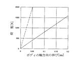
ここで、ボディ1Aの収容部2Aに印加した引っ張り荷重と収容部2Aの軸方向の伸びとの関係を図6に実線で示す。なお、図6中点線は、ボディ1の収容部2に印加した引っ張り荷重と収容部2の軸方向の伸びとの関係を示している。
図6から、ボディ1,1Aの収容部2,2Aは、軸方向の伸びが引っ張り荷重に比例して大きくなることがわかる。そして、ボディ1Aの収容部2Aは、薄肉の円筒部2aが形成されているので、収容部2に比べて、伸びやすくなっていることがわかる。
Here, the relationship between the tensile load applied to the
From FIG. 6, it can be seen that the
つぎに、皿ばねのたわみ量と荷重との関係を図7に示す。なお、図7中、実線は実施の形態3による燃料供給装置での皿ばねのたわみ量と荷重との関係を示し、点線は実施の形態1による燃料供給装置での皿ばねのたわみ量と荷重との関係を示す。また、図7中、荷重が必要荷重範囲の最小値(800N)の時における皿ばねのたわみ量をゼロとした。 Next, the relationship between the amount of deflection of the disc spring and the load is shown in FIG. In FIG. 7, the solid line shows the relationship between the amount of deflection of the disc spring and the load in the fuel supply device according to the third embodiment, and the dotted line shows the amount of deflection and the load of the disc spring in the fuel supply device according to the first embodiment. Shows the relationship. In FIG. 7, the amount of deflection of the disc spring when the load is the minimum value (800 N) of the required load range is set to zero.
図7から、実施の形態1の燃料供給装置では、たわみ量に対する荷重の勾配が大きいことがわかる。このことから、組立時に皿ばね34による荷重を必要荷重範囲内に確保するためには、構成部品の寸法ばらつきを小さく必要がある。さらに、組立後のボディ1の吸水による寸法変化を考慮すると、皿ばね34による荷重を必要荷重範囲内に確保するためには、構成部品の寸法ばらつきをさらに小さく必要がある。
From FIG. 7, it can be seen that in the fuel supply device of the first embodiment, the load gradient with respect to the deflection amount is large. For this reason, in order to ensure the load by the
この実施の形態3の燃料供給装置では、図7から、たわみ量に対する荷重の勾配が小さいことがわかる。これは、ボディ1Aの収容部2Aに肉薄の円筒部2aを設け、荷重に対するボディ1Aの軸方向の伸びを大きくしていることによるものである。そこで、構成部品の寸法ばらつきの公差を拡大しても、皿ばね34による荷重を必要荷重範囲内に確保することができる。さらに、組立後のボディ1Aの吸水による寸法変化が生じても、皿ばね34による荷重を必要荷重範囲内に確保することができる。
In the fuel supply device of the third embodiment, it can be seen from FIG. 7 that the load gradient with respect to the deflection amount is small. This is because the thin
このように、この実施の形態3によれば、ボディ1Aの収容部2Aに肉薄の円筒部2aを設け、荷重に対するボディ1Aの軸方向の伸びを大きくしているので、皿ばね34の使用可能範囲が拡大され、皿ばね34の使用可能範囲のマージン確保が可能となる。
Thus, according to the third embodiment, the thin
実施の形態4.
図8はこの発明の実施の形態4に係る燃料供給装置の構成を模式的に示す断面図である。
図8において、ボディ1Bは、有底円筒状の収容部2Bと、収容部2Bの底部に形成された吐出ポート4と、を備えている。また、駆動部35Aは、吸入ポート3が軸方向をシャフト47の軸心方向に一致させて外装材36に形成されている。
なお、他の構成は上記実施の形態1と同様に構成されている。
FIG. 8 is a cross-sectional view schematically showing the configuration of the fuel supply device according to
In FIG. 8, the body 1 </ b> B includes a bottomed cylindrical
Other configurations are the same as those in the first embodiment.
この実施の形態4による燃料供給装置は、ボディ1Bの軸心が鉛直方向を向き、駆動部35Aがボディ1Bに対して鉛直方向の上方に位置するように配置されている。
そこで、燃料は、燃料タンクから配管を介して吸入ポート3に導入され、軸受43、およびロータ44とステータ39との間の隙間を通って収容部2B内に吸入される。この時、燃料タンクからの低温の燃料が、モータ本体38を冷却する。
また、燃料は収容部2B内部および駆動部35A内部で加熱され、蒸気を発生する。この蒸気は、鉛直上方に移動し、吸入ポート3から燃料タンク側に戻される。これにより、収容部2B内および駆動部35A内の燃料の温度上昇が抑えられる。
The fuel supply device according to the fourth embodiment is arranged such that the axis of the body 1B faces the vertical direction, and the
Therefore, the fuel is introduced from the fuel tank into the suction port 3 through a pipe, and is sucked into the
Further, the fuel is heated inside the
この実施の形態4によれば、モータ本体38の冷却性が向上し、収容部2B内および駆動部35A内の燃料の温度上昇が抑えられるので、ボディ1Bの温度上昇が抑えられ、ボディ1Bでの吸水率の上昇が抑えられる。その結果、吸水に伴うボディ1Bの寸法変化が少なくなり、ボディ1Bの寸法変化に起因するバルブASSY21のシール部のシール性の悪化が抑えられる。
According to the fourth embodiment, the cooling performance of the motor
1,1A,1B ボディ、2,2A,2B 収容部、2a 円筒部、3 吸入ポート、4 吐出ポート、7 ケーシング、8 貫通穴、9 弁体(燃圧保持バルブ)、10 ボール(燃圧保持バルブ)、11 ばね(燃圧保持バルブ)、13 シリンダ、14 ピストン挿入穴、17 ピストン、19 スプリング、21 ブラシASSY、30 ブッシュ、34,50 皿ばね(弾性部材)、35,35A 駆動部、36 外装材、38 モータ本体部、43 軸受、47 シャフト、49 斜板。 1, 1A, 1B Body, 2, 2A, 2B Housing part, 2a Cylindrical part, 3 Suction port, 4 Discharge port, 7 Casing, 8 Through hole, 9 Valve body (fuel pressure holding valve), 10 ball (fuel pressure holding valve) , 11 Spring (fuel pressure holding valve), 13 cylinder, 14 piston insertion hole, 17 piston, 19 spring, 21 brush ASSY, 30 bush, 34, 50 disc spring (elastic member), 35, 35A drive unit, 36 exterior material, 38 Motor body, 43 Bearing, 47 Shaft, 49 Swash plate.
Claims (9)
樹脂製の外装材、該外装材内に設けられたモータ本体部、および該外装材内に軸受を介して回転自在に支持され、該モータ本体部により回転されるシャフトを有し、該シャフトの軸心を上記収容部の軸方向に一致させて、かつ該シャフトの一端を該収容部内に延出させて、上記外装材を該収容部に締着固定して該収容部の開口を塞口する駆動部と、
上記収容部内に延出する上記シャフトの一端に固着され、該シャフトの回転に連動して回転する斜板と、
上記収容部内に配設され、ピストン挿入穴が穴方向を該収容部の軸方向に一致させて形成された金属製のシリンダと、
ばねの付勢により上記斜板に支持されて上記ピストン挿入穴内に配設され、該斜板の回転に連動して該ピストン挿入穴内を摺動移動するピストンと、
上記収容部内の上記シリンダの吐出ポート側に配設された金属製のケーシングと、
上記収容部内の上記シリンダと上記ケーシングとの間に配設され、上記ピストンの動作に連動して上記燃料を上記シリンダ側から上記ケーシング側に供給する金属製のバルブASSYと、
上記ケーシングに穿設された貫通穴に装着され、該ケーシング側に供給された上記燃料が所定の圧力と超えると開成して該燃料を吐出ポート側に供給する燃圧保持バルブと、
上記収容部内の上記シリンダの駆動部側に配設されたブッシュと、
上記収容部の底部と上記ケーシングとの間に縮設され、該収容部の軸方向に配列された該ケーシング、上記バルブASSY、上記シリンダ、および上記ブッシュを互いに接触状態で上記外装材との間に加圧挟持する弾性部材と、
を備えることを特徴とする燃料供給装置。 A bottomed cylindrical housing portion, formed on the opening side of the housing portion, having a suction port for sucking fuel into the housing portion, and a discharge port formed at the bottom of the housing portion and discharging the fuel to the outside A resin body;
A resin exterior material, a motor body provided in the exterior material, a shaft rotatably supported by a bearing in the exterior material, and rotated by the motor body; The shaft center is aligned with the axial direction of the housing portion, and one end of the shaft is extended into the housing portion, and the exterior material is fastened and fixed to the housing portion, thereby closing the opening of the housing portion. A drive unit to
A swash plate fixed to one end of the shaft extending into the housing and rotating in conjunction with the rotation of the shaft;
A metal cylinder disposed in the housing portion and having a piston insertion hole formed so that the hole direction coincides with the axial direction of the housing portion;
A piston that is supported by the swash plate by biasing of a spring and disposed in the piston insertion hole, and that slides in the piston insertion hole in conjunction with rotation of the swash plate;
A metal casing disposed on the discharge port side of the cylinder in the housing;
A metal valve ASSY disposed between the cylinder in the housing and the casing and supplying the fuel from the cylinder side to the casing side in conjunction with the operation of the piston;
A fuel pressure holding valve that is attached to a through hole formed in the casing and opens when the fuel supplied to the casing exceeds a predetermined pressure and supplies the fuel to the discharge port;
A bush disposed on the drive part side of the cylinder in the housing part;
The casing, the valve ASSY, the cylinder, and the bush, which are arranged between the bottom of the housing portion and the casing and are arranged in the axial direction of the housing portion, are in contact with each other and the exterior material. An elastic member pressure-clamped on
A fuel supply device comprising:
樹脂製の外装材、該外装材内に設けられたモータ本体部、該外装材内に軸受を介して回転自在に支持され、該モータ本体部により回転されるシャフト、および該外装材に形成された吸入ポートを有し、該シャフトの軸心を上記収容部の軸方向に一致させて、かつ該シャフトの一端を該収容部内に延出させて、上記外装材を該収容部に締着固定して該収容部の開口を塞口する駆動部と、
上記収容部内に延出する上記シャフトの一端に固着され、該シャフトの回転に連動して回転する斜板と、
上記収容部内に配設され、ピストン挿入穴が穴方向を該収容部の軸方向に一致させて形成された金属製のシリンダと、
ばねの付勢により上記斜板に支持されて上記ピストン挿入穴内に配設され、該斜板の回転に連動して該ピストン挿入穴内を摺動移動するピストンと、
上記収容部内の上記シリンダの吐出ポート側に配設された金属製のケーシングと、
上記収容部内の上記シリンダと上記ケーシングとの間に配設され、上記ピストンの動作に連動して上記燃料を上記シリンダ側から上記ケーシング側に供給する金属製のバルブASSYと、
上記ケーシングに穿設された貫通穴に装着され、該ケーシング側に供給された上記燃料が所定の圧力と超えると開成して該燃料を吐出ポート側に供給する燃圧保持バルブと、
上記収容部内の上記シリンダの駆動部側に配設されたブッシュと、
上記収容部の底部と上記ケーシングとの間に縮設され、該収容部の軸方向に配列された該ケーシング、上記バルブASSY、上記シリンダ、および上記ブッシュを互いに接触状態で上記外装材との間に加圧挟持する弾性部材と、
を備えることを特徴とする燃料供給装置。 A resin-made body having a bottomed cylindrical housing portion and a discharge port formed at the bottom of the housing portion and discharging the fuel to the outside;
A resin exterior material, a motor body provided in the exterior material, a shaft rotatably supported in the exterior material via a bearing and rotated by the motor body, and formed in the exterior material The exterior member is fastened to the housing portion by aligning the axial center of the shaft with the axial direction of the housing portion and extending one end of the shaft into the housing portion. And a drive unit for closing the opening of the storage unit;
A swash plate fixed to one end of the shaft extending into the housing and rotating in conjunction with the rotation of the shaft;
A metal cylinder disposed in the housing portion and having a piston insertion hole formed so that the hole direction coincides with the axial direction of the housing portion;
A piston that is supported by the swash plate by biasing of a spring and disposed in the piston insertion hole, and that slides in the piston insertion hole in conjunction with rotation of the swash plate;
A metal casing disposed on the discharge port side of the cylinder in the housing;
A metal valve ASSY disposed between the cylinder in the housing and the casing and supplying the fuel from the cylinder side to the casing side in conjunction with the operation of the piston;
A fuel pressure holding valve that is attached to a through hole formed in the casing and opens when the fuel supplied to the casing exceeds a predetermined pressure and supplies the fuel to the discharge port;
A bush disposed on the drive part side of the cylinder in the housing part;
The casing, the valve ASSY, the cylinder, and the bush, which are arranged between the bottom of the housing portion and the casing and are arranged in the axial direction of the housing portion, are in contact with each other and the exterior material. An elastic member pressure-clamped on
A fuel supply device comprising:
Priority Applications (3)
| Application Number | Priority Date | Filing Date | Title |
|---|---|---|---|
| JP2007278702A JP4335938B2 (en) | 2007-10-26 | 2007-10-26 | Fuel supply device |
| DE200810017040 DE102008017040B4 (en) | 2007-10-26 | 2008-04-03 | Fuel supply apparatus |
| CN2008101249389A CN101418756B (en) | 2007-10-26 | 2008-06-17 | Fuel supply apparatus |
Applications Claiming Priority (1)
| Application Number | Priority Date | Filing Date | Title |
|---|---|---|---|
| JP2007278702A JP4335938B2 (en) | 2007-10-26 | 2007-10-26 | Fuel supply device |
Publications (2)
| Publication Number | Publication Date |
|---|---|
| JP2009108683A JP2009108683A (en) | 2009-05-21 |
| JP4335938B2 true JP4335938B2 (en) | 2009-09-30 |
Family
ID=40490386
Family Applications (1)
| Application Number | Title | Priority Date | Filing Date |
|---|---|---|---|
| JP2007278702A Expired - Fee Related JP4335938B2 (en) | 2007-10-26 | 2007-10-26 | Fuel supply device |
Country Status (3)
| Country | Link |
|---|---|
| JP (1) | JP4335938B2 (en) |
| CN (1) | CN101418756B (en) |
| DE (1) | DE102008017040B4 (en) |
Families Citing this family (8)
| Publication number | Priority date | Publication date | Assignee | Title |
|---|---|---|---|---|
| JP5208158B2 (en) * | 2010-04-26 | 2013-06-12 | 三菱電機株式会社 | Fuel supply device and fuel supply system |
| JP5367024B2 (en) * | 2011-08-03 | 2013-12-11 | 三菱電機株式会社 | Fuel supply device |
| JP5436646B1 (en) | 2012-11-15 | 2014-03-05 | 三菱電機株式会社 | Piston pump |
| JP6215993B2 (en) * | 2016-03-29 | 2017-10-18 | 株式会社ケーヒン | Fuel pump module |
| DE102016223838A1 (en) * | 2016-11-30 | 2018-05-30 | Robert Bosch Gmbh | Leakage test device of a tank arrangement |
| DE102017012018A1 (en) * | 2017-12-22 | 2019-06-27 | Mann+Hummel Gmbh | Filter system with check valve and filter element |
| DE102020210124A1 (en) | 2020-08-11 | 2022-02-17 | Robert Bosch Gesellschaft mit beschränkter Haftung | Metallic housing part, hydraulic axial piston machine with a metallic housing part and a cast core for casting a metallic housing part |
| DE102021125838A1 (en) * | 2021-10-05 | 2023-04-06 | Solo Kleinmotoren Gmbh | Piston high-pressure pump with small delivery volume |
Family Cites Families (4)
| Publication number | Priority date | Publication date | Assignee | Title |
|---|---|---|---|---|
| GB927005A (en) * | 1961-05-02 | 1963-05-22 | Budzich Tadeusz | Hydraulic pump or motor |
| EP0266744A3 (en) * | 1986-11-04 | 1990-01-17 | Joseph S. Cardillo | Ring valve pump |
| US5528976A (en) * | 1993-11-24 | 1996-06-25 | Kabushiki Kaisha Toyoda Jidoshokki Seisakusho | Swash plate type compressor with bearing assembly |
| DE19936662A1 (en) * | 1999-08-04 | 2001-02-15 | Pierburg Ag | Axial piston pump |
-
2007
- 2007-10-26 JP JP2007278702A patent/JP4335938B2/en not_active Expired - Fee Related
-
2008
- 2008-04-03 DE DE200810017040 patent/DE102008017040B4/en not_active Expired - Fee Related
- 2008-06-17 CN CN2008101249389A patent/CN101418756B/en not_active Expired - Fee Related
Also Published As
| Publication number | Publication date |
|---|---|
| JP2009108683A (en) | 2009-05-21 |
| DE102008017040A1 (en) | 2009-04-30 |
| DE102008017040B4 (en) | 2010-10-21 |
| CN101418756A (en) | 2009-04-29 |
| CN101418756B (en) | 2011-07-20 |
Similar Documents
| Publication | Publication Date | Title |
|---|---|---|
| JP4335938B2 (en) | Fuel supply device | |
| JP4650851B2 (en) | Fuel pressure adjusting device and fuel supply device including the same | |
| JP5474117B2 (en) | Electric pump and electric pump manufacturing method | |
| US9863422B2 (en) | Vacuum pump outlet valve | |
| US8857414B2 (en) | Vehicle fuel supply system | |
| JP2013514488A (en) | Motor pump unit | |
| WO2019098357A1 (en) | Centrifugal pump | |
| CN109372744B (en) | A kind of compressor | |
| US8261719B2 (en) | Fuel pump, in particular for a fuel system of a piston engine | |
| CN101205875A (en) | Fuel supply device | |
| JP4168602B2 (en) | Fuel supply system for outboard motor | |
| JP2012097640A (en) | Fuel supply apparatus | |
| CN109072846B (en) | High pressure pump | |
| JP5164573B2 (en) | Fuel supply device | |
| WO2022004431A1 (en) | High pressure pump | |
| KR101113405B1 (en) | Positive displacement compressor | |
| JP2010121485A (en) | Fuel supply device | |
| KR100899612B1 (en) | Fuel Pump for LPG Fuel | |
| JP5469117B2 (en) | Electric fluid pump | |
| JP2022013647A (en) | High pressure pump | |
| JP5436646B1 (en) | Piston pump | |
| JP2007218182A (en) | Relief valve and fuel supply device using same | |
| JP6769324B2 (en) | High pressure pump | |
| JP6921666B2 (en) | Pressure controller and fuel supply | |
| JP6095520B2 (en) | Fuel supply device |
Legal Events
| Date | Code | Title | Description |
|---|---|---|---|
| TRDD | Decision of grant or rejection written | ||
| A01 | Written decision to grant a patent or to grant a registration (utility model) |
Free format text: JAPANESE INTERMEDIATE CODE: A01 Effective date: 20090609 |
|
| A01 | Written decision to grant a patent or to grant a registration (utility model) |
Free format text: JAPANESE INTERMEDIATE CODE: A01 |
|
| A61 | First payment of annual fees (during grant procedure) |
Free format text: JAPANESE INTERMEDIATE CODE: A61 Effective date: 20090625 |
|
| FPAY | Renewal fee payment (event date is renewal date of database) |
Free format text: PAYMENT UNTIL: 20120703 Year of fee payment: 3 |
|
| R150 | Certificate of patent or registration of utility model |
Free format text: JAPANESE INTERMEDIATE CODE: R150 Ref document number: 4335938 Country of ref document: JP Free format text: JAPANESE INTERMEDIATE CODE: R150 |
|
| FPAY | Renewal fee payment (event date is renewal date of database) |
Free format text: PAYMENT UNTIL: 20120703 Year of fee payment: 3 |
|
| FPAY | Renewal fee payment (event date is renewal date of database) |
Free format text: PAYMENT UNTIL: 20130703 Year of fee payment: 4 |
|
| R250 | Receipt of annual fees |
Free format text: JAPANESE INTERMEDIATE CODE: R250 |
|
| R250 | Receipt of annual fees |
Free format text: JAPANESE INTERMEDIATE CODE: R250 |
|
| R250 | Receipt of annual fees |
Free format text: JAPANESE INTERMEDIATE CODE: R250 |
|
| R250 | Receipt of annual fees |
Free format text: JAPANESE INTERMEDIATE CODE: R250 |
|
| R250 | Receipt of annual fees |
Free format text: JAPANESE INTERMEDIATE CODE: R250 |
|
| R250 | Receipt of annual fees |
Free format text: JAPANESE INTERMEDIATE CODE: R250 |
|
| R250 | Receipt of annual fees |
Free format text: JAPANESE INTERMEDIATE CODE: R250 |
|
| R250 | Receipt of annual fees |
Free format text: JAPANESE INTERMEDIATE CODE: R250 |
|
| LAPS | Cancellation because of no payment of annual fees |