JP4334941B2 - container - Google Patents
container Download PDFInfo
- Publication number
- JP4334941B2 JP4334941B2 JP2003295028A JP2003295028A JP4334941B2 JP 4334941 B2 JP4334941 B2 JP 4334941B2 JP 2003295028 A JP2003295028 A JP 2003295028A JP 2003295028 A JP2003295028 A JP 2003295028A JP 4334941 B2 JP4334941 B2 JP 4334941B2
- Authority
- JP
- Japan
- Prior art keywords
- tray
- container
- cup
- peripheral
- shaped container
- Prior art date
- Legal status (The legal status is an assumption and is not a legal conclusion. Google has not performed a legal analysis and makes no representation as to the accuracy of the status listed.)
- Expired - Fee Related
Links
Images


Description
本発明は粉末状、顆粒状又は液状、ペースト状或いは固形状に加工された内容物、例えばコーヒー、紅茶、ジュース、スープ、和風汁物等の飲食物、義歯洗浄剤や含嗽剤或いは検査薬等を収納、封入するとともに、開封操作によって使用に供することのできる容器に関するものである。 The present invention includes powder, granular or liquid, paste or solid processed contents such as coffee, tea, juice, soup, Japanese-style soup and other foods, denture cleaning agents, gargles, or test agents. The present invention relates to a container that can be stored, sealed, and used by opening operation.
従来、コーヒー、紅茶、ジュース等の飲料およびスープ、味噌汁、お吸い物等の食品は、粉末状、顆粒状又はペースト状或いは固形状に加工されることによって、小分け包装された一人分或いは一カップ分の商品が提供され、通常個袋に封入された商品を開封して取り出し、別に用意したカップ、グラス或いは椀等に入れ、水或いは湯を注いで飲食に供するものである。また、これら溶解性飲食物商品では、より使用時の利便性を追求して、コーヒーにおいて、紙コップにコーヒー、ミルク、砂糖の個袋包装を複数個セットした商品も提供されている。しかしながら個袋の開封は、内容物の飛散や手指への付着を伴うことや包装材料によっては開け難いという欠点を持つものであった。同様に義歯洗浄剤や含嗽剤或いは検査薬等も個袋包装を開封して取り出し、別に用意した容器に入れて使用するという手間を要するものであった。 Conventionally, beverages such as coffee, tea, and juice, and foods such as soup, miso soup, and soup are processed into powder, granules, pastes, or solids, so that one serving or one cup is subdivided. This product is usually opened and taken out from the product enclosed in a single bag, put into a separately prepared cup, glass or bowl, etc., poured into water or hot water and served for eating and drinking. In addition, for these soluble food and drink products, there are also provided products in which a plurality of individual bags, coffee, milk, and sugar bags are set in a paper cup in pursuit of convenience during use. However, the opening of individual bags has the disadvantage that the contents are scattered and attached to fingers, and that it is difficult to open depending on the packaging material. Similarly, denture cleaning agents, gargles, inspection agents, and the like require time and effort to open and take out individual bags and put them in separate containers.
前記欠点を解消する為、カップ内部の、カップ底から適当な位置に仕切りが設けてあり、この仕切りが必要に応じて取り除くことができるようになった二重底カップと、この仕切りとカップ底の空間内に溶解性飲料物質が収納されたカップ飲料という技術が開示されている(例えば特許文献1参照。)。
上記文献に記載される考案に係る二重底カップおよびカップ飲料は、その実施例において、カップ内部で、底から適宜離れた位置に仕切りを、その周辺がカップ内壁に密着した状態で設けたものである。また、使用に際しては、仕切りの一端部に固着された紐等の引き手を引くことにより、仕切りを取り除くことができるものである。しかしながら、仕切りの周辺をカップ内壁に密着した状態とすることは、位置制御が難しいばかりでなく、カップ内壁の内周全てに密着する方法例えば熱溶着による場合にはカップ外壁側から全周にわたる受け具と共にカップ内壁側には仕切り周辺部を内側から加熱溶着する装置を必要とするなど、特別な冶具や装置を要するとともに、密着不良を起こし易いという欠点があった。 In the embodiment, the double bottom cup and the cup beverage according to the device described in the above document are provided with a partition at a position appropriately separated from the bottom inside the cup, with its periphery closely attached to the inner wall of the cup. It is. In use, the partition can be removed by pulling a handle such as a string fixed to one end of the partition. However, it is difficult to control the position of the periphery of the partition in close contact with the inner wall of the cup. In addition, a method of closely contacting the entire inner periphery of the cup inner wall, for example, by heat welding, receives the entire periphery from the cup outer wall side. In addition to the tools, a special jig or device is required on the inner wall side of the cup on the inner wall side of the cup, and there is a drawback that adhesion failure tends to occur.
そこで、本発明は、上記問題を解決するためになしたものであって、特別な冶具や装置を必要とせず、従来から有る容器蓋熱融着装置等を用いて、安定的且つ効率的に、内容物をカップ状容器内に封入するとともに、簡便な操作で開封し且つ使用することのできる容器を提供する。 Therefore, the present invention has been made to solve the above-described problems, and does not require a special jig or apparatus, and stably and efficiently using a conventional container lid heat fusion apparatus or the like. Provided is a container that can be opened and used by a simple operation while the contents are enclosed in a cup-shaped container.
上記課題を解決するため、請求項1の発明は、下面開放部下端に周鍔部を有し且つ前記周鍔部に引き剥がしタブを備えたトレー状容器に内容物を収納し、紙を主強度材とし最内層に熱接着性樹脂層を有する積層体からなり底壁と底壁から立設される周壁で形成され上面が開放したカップ状容器の前記底壁の内面に前記トレー状容器の周鍔部を引き剥がし可能に接着されており、前記トレー状容器が表層に樹脂層を最内層に易開封性溶着樹脂層を有するプラスチック製トレーからなり前記周鍔部の外縁から一部突設すると共に前記外縁で屈曲自在とした固着部を有し、前記引き剥がしタブが基材層と表層となる熱融着樹脂層とからなり、前記引き剥がしタブの前記熱融着樹脂層と前記トレー状容器の前記樹脂層とを当接させ前記引き剥がしタブの端部が前記トレー状容器の周鍔部の外縁から突設された固着部に熱融着にて固着され、前記トレー状容器の周鍔部の外縁で屈曲された固着部から前記カップ状容器の周壁の内面に沿って延び該周壁の上端縁に掛止めされてなり、前記引き剥がしタブの引き上げ操作により、前記カップ状容器の底壁に接着された前記トレー状容器の周鍔部が引き剥がされ、前記トレー状容器に収納された内容物を前記カップ状容器内に顕わし出して使用に供する構成としたことにより、接着位置の制御が安定的に行えるとともに、簡単な接着工程で安定的且つ効率良く接着して溶解性飲食物を封入することができ、トレー状容器の周鍔部に引き剥がしタブを固着するとともにカップ状容器の底壁に引き剥がし可能な接着状態としたので、簡便な開封操作により開封することができる。また、引き剥がしタブを別体に形成してトレー状容器の周鍔部の外縁から突設すると共に前記外縁で屈曲自在とした固着部に固着する構造は、引き剥がしの応力が伝わりやすい構造とすることができ、しかも、トレー状容器の形成時に無用な成形サイズの増大を避け、さらにトレー状容器と引き剥がしタブに必要な材質をそれぞれ独自に選定することが出来るとともに、成形の面付けに無駄な余白等を生じさせないので、材料面の無駄を省くことが出来る。 In order to solve the above problems, the invention of claim 1 is characterized in that the contents are stored in a tray-like container having a peripheral flange portion at the lower end of the lower surface opening portion and provided with a tear-off tab on the peripheral flange portion. The tray-shaped container is formed on the inner surface of the bottom wall of the cup-shaped container which is formed of a laminated body having a thermal adhesive resin layer as an innermost layer as a strength material and is formed by a peripheral wall standing upright from the bottom wall and the bottom wall. Peripheral part is peelably bonded, and the tray-like container is made of a plastic tray with a resin layer on the surface and an easily openable welded resin layer on the innermost layer, partially protruding from the outer edge of the peripheral part And the peelable tab comprises a base layer and a heat-sealing resin layer as a surface layer, and the heat-sealing resin layer and the tray of the peeling tab The peeling tab by contacting the resin layer of the container The cup-shaped container is fixed to the fixing portion protruding from the outer edge of the peripheral flange portion of the tray-like container by heat-sealing and bent at the outer edge of the peripheral edge portion of the tray-shaped container. It extends along the inner surface of the peripheral wall of the peripheral wall and is hooked to the upper edge of the peripheral wall, and the pulling operation of the peeling tab pulls the peripheral flange of the tray-shaped container bonded to the bottom wall of the cup-shaped container. The peeled-off contents stored in the tray-like container are exposed to the cup-like container for use, so that the bonding position can be stably controlled and stable with a simple bonding process. It is possible to enclose a soluble food and beverage by adhering efficiently and efficiently, and because it is in an adhesive state that can be peeled off to the bottom wall of the cup-shaped container while fixing the peeling tab to the peripheral flange portion of the tray-shaped container, Simple opening operation It can be opened. In addition, the structure in which the peeling tab is formed separately and protrudes from the outer edge of the peripheral flange portion of the tray-like container and is fixed to the fixing portion that can be bent at the outer edge is a structure in which the peeling stress is easily transmitted. In addition, it is possible to avoid unnecessary increase in molding size when forming a tray-shaped container, and to select the materials necessary for the tray-shaped container and the tear-off tab, respectively, and for imposition of molding. Since there is no useless blank space, it is possible to eliminate material waste.
本発明の容器は、予めコーヒー等の内容物がカップ状容器の底壁に接着されたトレー状容器内に封入されており、トレー状容器の周鍔部に一体に延設され、又は別体に形成され固着された引き剥がしタブを操作すればトレー状容器が引き剥がされ、内容物を自動的にカップ状容器内に顕わし出すことができるから、内容物の飛散や手指への付着が発生せず、しかも開封を容易に行えるので、使用の簡便性・快適性で優れている。 The container of the present invention is enclosed in a tray-like container in which contents such as coffee are previously bonded to the bottom wall of the cup-like container, and is integrally extended to the peripheral flange portion of the tray-like container, or is a separate body. By operating the peeling tab formed and fixed, the tray-like container is peeled off, and the contents can be automatically revealed in the cup-like container, so that the contents can be scattered and adhered to fingers. Since it does not occur and can be opened easily, it is excellent in ease of use and comfort.
また本発明の容器は、カップ状容器の底壁内面にトレー状容器の周鍔部を接着する構造であるので、位置制御が容易かつ安定し、かつ密着性が損なわれることが無い。しかも一般的に用いられているトレーシールシステムを大きく変更することなく製造することが出来る為、生産性・経済性に優れている。 Moreover, since the container of this invention is the structure which adhere | attaches the surrounding collar part of a tray-shaped container on the bottom wall inner surface of a cup-shaped container, position control is easy and stable, and adhesiveness is not impaired. Moreover, since it can be manufactured without greatly changing the generally used tray seal system, it is excellent in productivity and economy.
上記本発明について、図面を用いて以下に詳述する。図1は本発明に係る容器の一実施例の断面図。図2は同じく一実施例の製造工程の説明図。図3はトレー状容器と引き剥がしタブの説明図。図4は同じく一実施例の集積ならびに販売状態を示す断面図である。 The present invention will be described in detail below with reference to the drawings. FIG. 1 is a cross-sectional view of an embodiment of a container according to the present invention. FIG. 2 is also an explanatory view of the manufacturing process of one embodiment. FIG. 3 is an explanatory view of a tray-like container and a peeling tab. FIG. 4 is a cross-sectional view showing the state of integration and sales in one embodiment.
図1は本発明に係る容器の一実施例の断面図で、底壁3と周壁4から構成されるカップ状容器1と、トレー底壁5、トレー周壁6およびトレー周鍔部7で構成されるトレー状容器2と、トレー周鍔部7に延設或いは取り付けられた引き剥がしタブ8とからなる容器において、前記トレー状容器2に収納された粉末コーヒー等の内容物Wは、前記トレー状容器2のトレー周鍔部7が前記カップ状容器1の底壁3の内面に加熱溶着されることにより、前記カップ状容器1内に封入されるとともに、前記トレー周鍔部7に取り付けられた引き剥がしタブ8が前記カップ状容器1の周壁4の内面に沿って延設されている状態を示している。
FIG. 1 is a cross-sectional view of an embodiment of a container according to the present invention, which is composed of a cup-shaped container 1 composed of a
図1に示された一実施例のカップ状容器1は紙カップであるが、材料構成としては紙を主強度材とし、最内層に熱可塑性樹脂を有することを基本としている。例えば、紙/ポリエチレン、ポリエチレン/紙/ポリエチレン、ポリプロピレン/紙/ポリプロピレン、紙/ポリエチレン/アルミニウム箔/ポリエチレン、ポリエチレン/紙/ポリエチレン/アルミニウム箔/ポリエチレン、ポリエチレン/アルミニウム箔/紙/ポリエチレンなどが挙げられる。特に封入される内容物Wが熱水溶解性飲食物の場合には、断熱性等の機能面から紙カップが望ましいが、冷水溶解性飲食物例えばジュース等の場合にはプラスチックカップでも良く、ポリプロピレン樹脂、ポリエチレン樹脂、ポリ塩化ビニル樹脂、ポリエチレンテレフタレート樹脂、ポリスチレン樹脂などを使用し、真空成形や圧空成形などのシートフォーミング法、射出成形法などの汎用成形法を用いて製造される。尚、カップ状容器1の形状は、通常の紙カップに用いられる逆円錐台型が生産面や、例えば販売チャネルとして考えられる飲料自働販売機での利用面から一般的であるが、これに限定されるものではなく、角型カップやその他の変形が可能であり、特にプラスチックカップを用いる場合は椀型や丼型等豊富な形状バリエーションが考えられる。 The cup-shaped container 1 of the embodiment shown in FIG. 1 is a paper cup, but the material constitution is basically that paper is a main strength material and the innermost layer has a thermoplastic resin. For example, paper / polyethylene, polyethylene / paper / polyethylene, polypropylene / paper / polypropylene, paper / polyethylene / aluminum foil / polyethylene, polyethylene / paper / polyethylene / aluminum foil / polyethylene, polyethylene / aluminum foil / paper / polyethylene, and the like. . In particular, when the content W to be enclosed is hot water soluble food or drink, a paper cup is desirable from the viewpoint of heat insulation and the like, but in the case of cold water soluble food or drink such as juice, a plastic cup may be used. , Polyethylene resin, polyvinyl chloride resin, polyethylene terephthalate resin, polystyrene resin, etc. are used, and they are manufactured using a general-purpose molding method such as a sheet forming method such as vacuum molding or pressure molding, or an injection molding method. In addition, the shape of the cup-shaped container 1 is generally an inverted truncated cone used for a normal paper cup from the viewpoint of production, for example, a beverage automatic vending machine considered as a sales channel, but is not limited thereto. However, a square cup and other modifications are possible. In particular, when a plastic cup is used, abundant shape variations such as a bowl or bowl can be considered.
同じく図1に示された一実施例のトレー状容器2は、真空成形や圧空成形などのシートフォーミング法、射出成形法などの汎用成形法を用いて製造されたプラスチック製トレーで、材料構成はポリプロピレン樹脂、ポリエチレン樹脂、ポリ塩化ビニル樹脂、ポリエチレンテレフタレート樹脂、ポリスチレン樹脂などを主強度材とし、最内層にイージーピールシーラント層すなわち易開封性溶着樹脂層を有している。易開封性溶着樹脂としてはポリプロピレン樹脂とポリエチレン樹脂、ポリエチレン樹脂とα‐オレフィン樹脂あるいはポリエチレン樹脂とポリスチレン樹脂をブレンドあるいは共重合した凝集破壊型、ポリエチレン‐酢酸ビニル樹脂を主体とする界面剥離型の樹脂を使用することができる。また、薄膜のポリエチレン層あるいはポリプロピレン層を剥離可能に主強度材の表面に配置した層間剥離型の樹脂を使用することも可能である。
Similarly, the tray-
図2は同じく一実施例の製造工程の説明図で、(a)は予め成形加工され、引き剥がしタブ8を固着したトレー状容器2が、該トレー状容器2のトレー周鍔部7で、リテーナーR上に載置され、内容物Wが前記トレー状容器2内に充填された状態を示す断面図である。(b)は前記内容物Wが充填収納され、引き剥がしタブ8を固着したトレー状容器2の上方から、予め成形加工された倒立状態のカップ状容器1が被せられる途中の状態を示す断面図で、この後前記トレー状容器2のトレー周鍔部7は前記カップ状容器1の底壁3の内面に当接することとなる。(c)は被せられた前記カップ状容器1の底壁3の外面上方からシールヘッドSが当接するとともに加熱溶着加工により、前記トレー状容器2のトレー周鍔部7の内面と、前記カップ状容器1の底壁3の内面とが溶着された状態を示す断面図で、内容物Wが封入されて製造を完了する。上述のごとく本発明の容器は、一般に用いられているトレーシールシステムを大きく変更することなく製造することが出来る。
FIG. 2 is also an explanatory diagram of the manufacturing process of one embodiment. (A) is a tray-
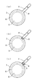
図3は、トレー状容器と引き剥がしタブの説明図で、トレー状容器を平面から見た状態の模式図である。(a)はトレー状容器2のトレー周鍔部7の外縁部分から一体に所定の幅と長さを持つ引き剥がしタブ8を延設する形式で、点線で示したトレー周鍔部外縁Pを屈曲自在としたものである。(b)はトレー状容器2のトレー周鍔部7に、別体として形成した所定の幅と長さを持つ引き剥がしタブ8を固着した形式である。該引き剥がしタブ8の材質としては、アルミ箔/ポリエチレン樹脂、アルミ箔/ポリプロピレン樹脂、紙/ポリエステルフィルム/ポリエチレン樹脂、紙/ポリエステルフィルム/ポリプロピレン樹脂など前記トレー状容器2のトレー周鍔部7と熱融着できるとともに、形状を保持できる程度の剛性を備え、かつ引き上げ操作に耐える強度を持つものが望ましい。(c)はトレー状容器2のトレー周鍔部7の外縁部分から一部突設した固着部分に、前述のごとく別体として形成した所定の幅と長さを持つ引き剥がしタブ8を固着するとともに、トレー周鍔部外縁Pを屈曲自在としたものである。尚、斜線ハッチングで示した固着部Qの固着方法としては、加熱溶着等一般的に用いられる方法による。
FIG. 3 is an explanatory view of the tray-like container and the peeling tab, and is a schematic view of the tray-like container as viewed from the plane. (A) is a form in which a
本発明に係る容器の使用にあたっては、引き剥がしタブ8を引き上げる操作によって、カップ状容器1の底壁3に接着されたトレー状容器2のトレー周鍔部7が引き剥がされ、内容物Wをカップ状容器1内に顕わし出すことが出来、これに熱湯あるいは冷水等を注入して内容物Wを溶解させて使用に供する。
In using the container according to the present invention, the tray
図4は同じく一実施例の集積ならびに販売状態を示す断面図で、前述のごとくカップ状容器1が紙カップの場合は逆円錐台型形状が一般的であるから、図4のようにスタックすることが可能であり、他の形状あるいはプラスチックカップを使用する場合も、周壁4にテーパ角度を持たせてスタック性を付与することが一般的に行われる。本発明の容器は、封入される内容物Wの容量や周壁4のテーパ角度の設計により差があるものの、カップ状容器1の底壁3にトレー状容器2のトレー周鍔部7を接着して形成されるので、スタック性を大きく損なうことが無く、特に紙カップの場合、トレー状容器2のトレー周壁6とトレー底壁5とで形成される膨出部が、紙カップの糸底部分に嵌まり込むことで、スタックサイズをより小さくする。これにより製品の集積、梱包、保管、輸送等のサイズダウンが可能で、経済的効果を期待できる。
FIG. 4 is a cross-sectional view showing the state of accumulation and sales in one embodiment. When the cup-shaped container 1 is a paper cup as described above, an inverted frustoconical shape is generally used, and stacking as shown in FIG. In the case where other shapes or plastic cups are used, it is generally performed that the
また、本発明の容器は、単品或いは図4に示すように、複数個の製品をスタックした状態で、製品全体或いは開口部方向の上半部分を熱収縮包装することや、真空成形法で形成されたプラスチック成形キャップを取り付けることで販売状態として使用できる。さらに前述のようにスタックされた状態での自働販売機への供給も可能である。 Also, the container of the present invention is formed by heat shrink wrapping the whole product or the upper half of the opening direction in a state where a plurality of products are stacked or a vacuum forming method as shown in FIG. It can be used as a sales state by attaching a plastic molded cap. Further, it can be supplied to the vending machine in a stacked state as described above.
1 カップ状容器
2 トレー状容器
3 底壁
4 周壁
5 トレー底壁
6 トレー周壁
7 トレー周鍔部
8 引き剥がしタブ
P 周鍔部外縁
Q 固着部
R リテーナー
S シールヘッド
W 内容物
1 cup-shaped container
2 Tray container
3 Bottom wall
4 wall
5 Tray bottom wall
6 Tray wall
7 Tray circumference
8 Stripping tab
P Circumference outer edge
Q Adhering part
R retainer
S Seal head
W Contents
Claims (1)
Priority Applications (1)
| Application Number | Priority Date | Filing Date | Title |
|---|---|---|---|
| JP2003295028A JP4334941B2 (en) | 2003-08-19 | 2003-08-19 | container |
Applications Claiming Priority (1)
| Application Number | Priority Date | Filing Date | Title |
|---|---|---|---|
| JP2003295028A JP4334941B2 (en) | 2003-08-19 | 2003-08-19 | container |
Publications (2)
| Publication Number | Publication Date |
|---|---|
| JP2005059929A JP2005059929A (en) | 2005-03-10 |
| JP4334941B2 true JP4334941B2 (en) | 2009-09-30 |
Family
ID=34371392
Family Applications (1)
| Application Number | Title | Priority Date | Filing Date |
|---|---|---|---|
| JP2003295028A Expired - Fee Related JP4334941B2 (en) | 2003-08-19 | 2003-08-19 | container |
Country Status (1)
| Country | Link |
|---|---|
| JP (1) | JP4334941B2 (en) |
-
2003
- 2003-08-19 JP JP2003295028A patent/JP4334941B2/en not_active Expired - Fee Related
Also Published As
| Publication number | Publication date |
|---|---|
| JP2005059929A (en) | 2005-03-10 |
Similar Documents
| Publication | Publication Date | Title |
|---|---|---|
| US6708735B1 (en) | Dispensing lid closure for confections and methods of making and using the closure | |
| RU2431588C2 (en) | Method of jointing neck to elastic film bag | |
| AU2011101266A4 (en) | A blister pack for a container | |
| US5839627A (en) | Container having improved reclosable pour spout mounted thereon and process therefor | |
| JP5691153B2 (en) | Package with sealing lid | |
| EP2340210B1 (en) | Nutritive substance delivery container | |
| KR20120003850A (en) | Environmentally friendly liquid container and method of manufacture | |
| JPH0741915B2 (en) | Pack container and manufacturing method thereof | |
| US4978056A (en) | Packaging | |
| CA2919304C (en) | Two compartment plastic containers and food product pack comprising such containers | |
| JP2009541168A (en) | Packaged food products | |
| EP1538105B1 (en) | Bag-like container with sealed spout | |
| JP4334941B2 (en) | container | |
| JP2006248556A (en) | Portion-controlled container | |
| JP4457784B2 (en) | Easy-open container | |
| EP1529742A1 (en) | Container, with additional reservoir and method for packaging a substance | |
| RU2762839C1 (en) | Packaging with a detachable closing structural element | |
| JP5327031B2 (en) | Easy-open container | |
| CN202358484U (en) | Disposable multi-cup-body packaging structure | |
| JP2571569B2 (en) | Easy-open sealed container with drop lid for container | |
| JP4043590B2 (en) | Cup composite container with sauce | |
| JPH0331714Y2 (en) | ||
| JP3397504B2 (en) | Container with seal lid | |
| JP2006519147A (en) | Internal safety sealing device | |
| JP2000142716A (en) | Indifinitely shaped container |
Legal Events
| Date | Code | Title | Description |
|---|---|---|---|
| A621 | Written request for application examination |
Free format text: JAPANESE INTERMEDIATE CODE: A621 Effective date: 20060713 |
|
| A977 | Report on retrieval |
Free format text: JAPANESE INTERMEDIATE CODE: A971007 Effective date: 20081020 |
|
| A131 | Notification of reasons for refusal |
Free format text: JAPANESE INTERMEDIATE CODE: A131 Effective date: 20081028 |
|
| A521 | Written amendment |
Free format text: JAPANESE INTERMEDIATE CODE: A523 Effective date: 20081211 |
|
| A02 | Decision of refusal |
Free format text: JAPANESE INTERMEDIATE CODE: A02 Effective date: 20090204 |
|
| A521 | Written amendment |
Free format text: JAPANESE INTERMEDIATE CODE: A523 Effective date: 20090304 |
|
| A521 | Written amendment |
Free format text: JAPANESE INTERMEDIATE CODE: A523 Effective date: 20090304 |
|
| A911 | Transfer of reconsideration by examiner before appeal (zenchi) |
Free format text: JAPANESE INTERMEDIATE CODE: A911 Effective date: 20090413 |
|
| TRDD | Decision of grant or rejection written | ||
| A01 | Written decision to grant a patent or to grant a registration (utility model) |
Free format text: JAPANESE INTERMEDIATE CODE: A01 Effective date: 20090623 |
|
| A01 | Written decision to grant a patent or to grant a registration (utility model) |
Free format text: JAPANESE INTERMEDIATE CODE: A01 |
|
| A61 | First payment of annual fees (during grant procedure) |
Free format text: JAPANESE INTERMEDIATE CODE: A61 Effective date: 20090624 |
|
| FPAY | Renewal fee payment (prs date is renewal date of database) |
Free format text: PAYMENT UNTIL: 20120703 Year of fee payment: 3 |
|
| R150 | Certificate of patent (=grant) or registration of utility model |
Free format text: JAPANESE INTERMEDIATE CODE: R150 |
|
| FPAY | Renewal fee payment (prs date is renewal date of database) |
Free format text: PAYMENT UNTIL: 20120703 Year of fee payment: 3 |
|
| FPAY | Renewal fee payment (prs date is renewal date of database) |
Free format text: PAYMENT UNTIL: 20130703 Year of fee payment: 4 |
|
| LAPS | Cancellation because of no payment of annual fees |