JP4333887B2 - Vehicle headlamp device - Google Patents
Vehicle headlamp device Download PDFInfo
- Publication number
- JP4333887B2 JP4333887B2 JP09143299A JP9143299A JP4333887B2 JP 4333887 B2 JP4333887 B2 JP 4333887B2 JP 09143299 A JP09143299 A JP 09143299A JP 9143299 A JP9143299 A JP 9143299A JP 4333887 B2 JP4333887 B2 JP 4333887B2
- Authority
- JP
- Japan
- Prior art keywords
- beam lamp
- low beam
- reflector
- lamp
- lamps
- Prior art date
- Legal status (The legal status is an assumption and is not a legal conclusion. Google has not performed a legal analysis and makes no representation as to the accuracy of the status listed.)
- Expired - Lifetime
Links
- 230000003287 optical effect Effects 0.000 claims description 14
- 238000010586 diagram Methods 0.000 description 6
- 230000000694 effects Effects 0.000 description 6
- 229910052736 halogen Inorganic materials 0.000 description 6
- 150000002367 halogens Chemical class 0.000 description 6
- 239000002828 fuel tank Substances 0.000 description 3
- 229910052724 xenon Inorganic materials 0.000 description 3
- FHNFHKCVQCLJFQ-UHFFFAOYSA-N xenon atom Chemical compound [Xe] FHNFHKCVQCLJFQ-UHFFFAOYSA-N 0.000 description 3
- 230000004913 activation Effects 0.000 description 2
- 230000001678 irradiating effect Effects 0.000 description 2
- QSHDDOUJBYECFT-UHFFFAOYSA-N mercury Chemical compound [Hg] QSHDDOUJBYECFT-UHFFFAOYSA-N 0.000 description 2
- 229910052753 mercury Inorganic materials 0.000 description 2
- 229910001507 metal halide Inorganic materials 0.000 description 2
- 150000005309 metal halides Chemical class 0.000 description 2
- 239000007858 starting material Substances 0.000 description 2
- 239000013013 elastic material Substances 0.000 description 1
- 230000002708 enhancing effect Effects 0.000 description 1
- 239000000446 fuel Substances 0.000 description 1
- 238000002347 injection Methods 0.000 description 1
- 239000007924 injection Substances 0.000 description 1
- 238000012423 maintenance Methods 0.000 description 1
- -1 mercury halide Chemical class 0.000 description 1
- 230000000116 mitigating effect Effects 0.000 description 1
- 230000002265 prevention Effects 0.000 description 1
- 239000000725 suspension Substances 0.000 description 1
- 230000002459 sustained effect Effects 0.000 description 1
- 238000011144 upstream manufacturing Methods 0.000 description 1
Images
Classifications
-
- B—PERFORMING OPERATIONS; TRANSPORTING
- B60—VEHICLES IN GENERAL
- B60Q—ARRANGEMENT OF SIGNALLING OR LIGHTING DEVICES, THE MOUNTING OR SUPPORTING THEREOF OR CIRCUITS THEREFOR, FOR VEHICLES IN GENERAL
- B60Q1/00—Arrangement of optical signalling or lighting devices, the mounting or supporting thereof or circuits therefor
- B60Q1/0088—Details of electrical connections
- B60Q1/0094—Arrangement of electronic circuits separated from the light source, e.g. mounting of housings for starter circuits for discharge lamps
-
- B—PERFORMING OPERATIONS; TRANSPORTING
- B60—VEHICLES IN GENERAL
- B60Q—ARRANGEMENT OF SIGNALLING OR LIGHTING DEVICES, THE MOUNTING OR SUPPORTING THEREOF OR CIRCUITS THEREFOR, FOR VEHICLES IN GENERAL
- B60Q1/00—Arrangement of optical signalling or lighting devices, the mounting or supporting thereof or circuits therefor
- B60Q1/0029—Spatial arrangement
- B60Q1/0041—Spatial arrangement of several lamps in relation to each other
-
- B—PERFORMING OPERATIONS; TRANSPORTING
- B60—VEHICLES IN GENERAL
- B60Q—ARRANGEMENT OF SIGNALLING OR LIGHTING DEVICES, THE MOUNTING OR SUPPORTING THEREOF OR CIRCUITS THEREFOR, FOR VEHICLES IN GENERAL
- B60Q1/00—Arrangement of optical signalling or lighting devices, the mounting or supporting thereof or circuits therefor
- B60Q1/02—Arrangement of optical signalling or lighting devices, the mounting or supporting thereof or circuits therefor the devices being primarily intended to illuminate the way ahead or to illuminate other areas of way or environments
- B60Q1/04—Arrangement of optical signalling or lighting devices, the mounting or supporting thereof or circuits therefor the devices being primarily intended to illuminate the way ahead or to illuminate other areas of way or environments the devices being headlights
- B60Q1/06—Arrangement of optical signalling or lighting devices, the mounting or supporting thereof or circuits therefor the devices being primarily intended to illuminate the way ahead or to illuminate other areas of way or environments the devices being headlights adjustable, e.g. remotely-controlled from inside vehicle
- B60Q1/076—Arrangement of optical signalling or lighting devices, the mounting or supporting thereof or circuits therefor the devices being primarily intended to illuminate the way ahead or to illuminate other areas of way or environments the devices being headlights adjustable, e.g. remotely-controlled from inside vehicle by electrical means including means to transmit the movements, e.g. shafts or joints
-
- B—PERFORMING OPERATIONS; TRANSPORTING
- B62—LAND VEHICLES FOR TRAVELLING OTHERWISE THAN ON RAILS
- B62J—CYCLE SADDLES OR SEATS; AUXILIARY DEVICES OR ACCESSORIES SPECIALLY ADAPTED TO CYCLES AND NOT OTHERWISE PROVIDED FOR, e.g. ARTICLE CARRIERS OR CYCLE PROTECTORS
- B62J6/00—Arrangement of optical signalling or lighting devices on cycles; Mounting or supporting thereof; Circuits therefor
- B62J6/02—Headlights
- B62J6/022—Headlights specially adapted for motorcycles or the like
- B62J6/024—Switching between high and low beam
-
- B—PERFORMING OPERATIONS; TRANSPORTING
- B62—LAND VEHICLES FOR TRAVELLING OTHERWISE THAN ON RAILS
- B62J—CYCLE SADDLES OR SEATS; AUXILIARY DEVICES OR ACCESSORIES SPECIALLY ADAPTED TO CYCLES AND NOT OTHERWISE PROVIDED FOR, e.g. ARTICLE CARRIERS OR CYCLE PROTECTORS
- B62J6/00—Arrangement of optical signalling or lighting devices on cycles; Mounting or supporting thereof; Circuits therefor
- B62J6/02—Headlights
- B62J6/022—Headlights specially adapted for motorcycles or the like
- B62J6/026—Headlights specially adapted for motorcycles or the like characterised by the structure, e.g. casings
-
- B—PERFORMING OPERATIONS; TRANSPORTING
- B60—VEHICLES IN GENERAL
- B60Q—ARRANGEMENT OF SIGNALLING OR LIGHTING DEVICES, THE MOUNTING OR SUPPORTING THEREOF OR CIRCUITS THEREFOR, FOR VEHICLES IN GENERAL
- B60Q2200/00—Special features or arrangements of vehicle headlamps
- B60Q2200/30—Special arrangements for adjusting headlamps, e.g. means for transmitting the movements for adjusting the lamps
- B60Q2200/36—Conjoint adjustments, i.e. a mechanical link allows conjoint adjustment of several units
Landscapes
- Engineering & Computer Science (AREA)
- Mechanical Engineering (AREA)
- Lighting Device Outwards From Vehicle And Optical Signal (AREA)
- Non-Portable Lighting Devices Or Systems Thereof (AREA)
Description
【0001】
【発明の属する技術分野】
本発明は、車両用前照灯装置に関し、特に、ロービームおよびハイビームの双方に適した配光と外観上のアクセント効果を高めるのに好適な車両用前照灯装置に関する。
【0002】
【従来の技術】
前面にカウリングを備えた車両で、そのカウリングに4灯式の前照灯(ヘッドライト)を支持させたものが知られている。4灯式ヘッドライトのうち中央部の2灯はロービーム用であり、その左右の2灯はハイビーム用である。ところで、カウリングは高速走行時に車両前面で受ける空気の抵抗を軽減して走行性を高める目的で設けられるが、4灯の灯具を左右に並べたのでは、カウリングの幅が大きくなるために空気抵抗軽減の面から不利であり、かつ美感においても見劣りがする。特に、十分な光量を得ようとすると、リフレクタの直径が大きくなって、一層幅が大きくなる。
【0003】
そこで、このような不具合を解消するため、反射鏡で反射された光を、凸レンズを通過させて前方に投射するプロジェクタ式のヘッドライトを採用することにより、リフレクタを小さくしてカウリングの幅を小さくした二輪車が提案されている(特開平2−136383号公報)。
【0004】
【発明が解決しようとする課題】
上記従来のヘッドライトは、ロービームとハイビームとで発光位置が変化するので外観上のアクセントとなるが、4灯がすべて同種の光源であるため、アクセント効果が弱い。さらに、ロービームおよびハイビームのそれぞれに適した配光特性を得にくいという問題点もある。すなわち、ロービームは比較的近距離を広範囲に照射する必要があるし、ハイビームは遠距離をスポット的に照射できることが要求されるが、従来のヘッドライトではこのような特性を得にくい。
【0005】
また、プロジェクタ式のヘッドライトでは灯具が長くなるため、ヘッドライト後方に設置される計器等の部品のレイアウトが制限されるという問題点もある。い。
【0006】
本発明は、上述の課題を解決し、ロービームおよびハイビーム切り替え時のアクセント効果を高めると共に、配光特性を適正にでき、併せてヘッドライト後方のレイアウトの自由度を高めることができる車両用前照灯装置を提供することを目的とする。
【0007】
【課題を解決するための手段】
上記目的を達成するための本発明は、ロービーム用灯具およびハイビーム用灯具を車両の前部左右にそれぞれ1組ずつ配置してなる車両用前照灯装置において、前記各組の灯具のうち車両中央寄りにはロービーム用灯具を配置し、車両側部寄りには前記ロービーム用灯具よりも高位置にハイビーム用灯具を配置するとともに、前記ロービーム用灯具のリフレクタ面を前記ハイビーム用灯具のリフレクタ面よりも大きく設定し、かつ、各組の灯具を覆うレンズ面は、前記各リフレクタ面に対応して、ロービーム用灯具側からハイビーム用灯具側へ漸次小さくなるように設定している点に第1の特徴がある。また、本発明は、前記ロービーム用灯具の光源が放電管である点に第2の特徴がある。さらに、本発明は、前記各組の灯具間にそれぞれの放電管用昇圧装置を配置した点に第3の特徴がある。
【0008】
第1の特徴によれば、ロービームは大きいリフレクタ面で反射されて前方の広い範囲を照射し、ハイビームは小さいリフレクタ面で反射されてスポット光として前遠方を照射する。また、ハイビームとロービームはそれぞれ異なる高さから照射されるのでハイビームおよびロービームの切替時のアクセント効果が大きい。特に、第2の特徴によれば、放電管はハロゲンランプ等と異なり、強く発光するので、ロービームとして好適な広い配光が可能である。また、第3の特徴によれば、放電管に近い位置に放電管用昇圧装置が配置されるので、ノイズ対策が必要な高圧シールド線を短くでき、ノイズ防止をより有効に行うことができる。さらに、車両の中央に放電管用昇圧装置を位置させることでバランス的にも好ましい配置である。
【0009】
また、本発明は、前記ロービーム用灯具および前記ハイビーム用灯具のリフレクタ面を一体で形成したリフレクタを有し、光軸調節のために該リフレクタを上下に回動させる調節手段を設けるとともに、前記リフレクタの回動中心軸を前記ロービーム用灯具の光軸を所望に調節できるように該ロービーム用灯具のリフレクタ面に関して設定した点に第4の特徴がある。さらに、本発明は、前記調節手段が、電動モータを含み、該電動モータによって前記リフレクタを上下に回動させ点に第5の特徴がある。
【0010】
第4の特徴によれば、強い発光を有するロービームを、運転に適した方向に正確に照射することができる。特に、第5の特徴によれば、電動で光軸調節ができるので運転者の負担を軽減できるとともに正確な調節が可能である。
【0011】
【発明の実施の形態】
以下、図面を参照して本発明を説明する。なお、以下の説明では、同一または同等部分は同符号をもって示す。図4は、本発明の一実施形態に係るヘッドライトを搭載した自動二輪車の外観を示す側面図である。同図において、自動二輪車(以下、「車両」という)1は水平対向6気筒型のエンジン2を搭載しており、そのフレーム構造は、ステアリングヘッド3から車両後方へ二叉に延びたツインフレーム形式のメインフレーム4とこのメインフレーム4から後方に結合されたリアフレーム5とから構成されている。ステアリングヘッド3には走行方向左右に配置された2本のパイプからなるフロントフォーク6が操舵方向に回動自在に設けられており、その上部つまりトップブリッジにハンドル7が固定されている。フロントフォーク6の下端に設けられた前輪軸8には前輪9が回転自在に支持されている。
【0012】
ハンドル7の前面には表示パネルや制御部からなるメータユニット10が設けられている。車両1の前部を覆うフロントカウル11の前方には灯火装置のレンズ面(クリアレンズ)12が取り付けられている。フロントカウル11内には、灯火装置として使用されている放電灯の昇圧装置(バラスト)13が収容されている。フロントカウル11の上部には風防スクリーン14が設けられ、風防スクリーン14の取付部近傍には空気導入口15が形成されている。
【0013】
メインフレーム4上には燃料タンク16が設けられ、その後方には、リフフレーム5上に搭載された運転者シート17および同乗者シート18が配置されている。同乗者シート18は運転者シート17と一体に形成されていて、かつ、背もたれ19を有する。背もたれ19の背後にはリアフレームリアトランク20が設けられている。リアトランク20の後部にはリアストップランプ21およびウインカライト22が設けられている。リアトランク20の下方、後輪26の左右にはサイドトランク23が設けられ、その後部にはもう一組のリアストップランプ24およびウインカライト25が設けられている。
【0014】
燃料タンク16の下部前方にはエアクリーナ27が設けられ、エアクリーナ27の前方に設けられたスロットルボディ28はインテークマニホルド29が伸びている。インテークマニホルド29は対向配置された3気筒にそれぞれ結合されていてこれらの気筒の上流には図示しない燃料噴射装置が配置されている。エンジン2から後方へエキゾーストマニホルド30が引出されていて、このエキゾーストマニホルド30はマフラ31に連結されている。
【0015】
なお、運転者シート17の下方両側はサイドカバー32で覆われ、エンジン2の前方にはフロントロアカウル33が配置されている。また、運転者シート17の下部にはリアクッション34が設けられている。このリアクッション34は電動でばね力を調節して運転者の体重に応じてサスペンションの初期加重を調整することができる油圧ユニット(図示しない)に結合されている。車両1はスタンド35を使用して自立させることができる。
【0016】
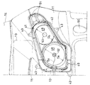
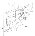
次に、前記車両の前部構造を説明する。図1は車両の要部正面図、図2は同側面断面図、図3は同平面図であり、図4と同符号は同一または同等部分である。なお、これらの図は車両の左半分のみを示している。フロントカウル11には、ヘッドライト40がそのレンズ面12を車両前方に露出させて設けられている。ヘッドライト40はレンズ面12およびこのレンズ面12の後方に取り付けられたリフレクタ41と、このリフレクタ41を後方から覆うカバー42とを有している。そして、ヘッドライト40はケース42から周囲に張り出した4か所の取付部43をフロントカウル11のボス44に固定することによってフロントカウル11に支持されている。なお、リフレクタ41は、ヘッドライト40の光軸調節を可能とするため、後述するようにケース42に対して揺動自在に支持されている。
【0017】
ステアリングヘッド3には、前方に突出したブラケット45が取付けられている。そして、ブラケット45の先端およびこのブラケット45に支持されたステー46の先端がフロントカウル11に連結されることにより、フロントカウル11はステアリングヘッド3を介して車体のフレームに固定されている。なお、フロントカウル11には下部および上部にそれぞれエアスクープ50,51が設けられている。また、風防スクリーン14は部材47によって上下方向に位置調節ができるようにフロントカウル11に取り付けられている。
【0018】
図1に示したように、ヘッドライト40のリフレクタ41は2つのリフレクタ面48,49を有しており、リフレクタ面48の直径Daの方が、リフレクタ面49の直径Dbよりも大きい。一例として、直径Daは120mm、直径Dbは100mmである。車両1の中央部寄りのリフレクタ面48よりも車両1の側寄りのリフレクタ面49の方が上位に位置させている。
【0019】
したがって、このようなリフレクタ面48および49を有するリフレクタ41に合わせて、レンズ面12も車両1の中央部寄りが幅広で車両1の側寄りが幅狭に形成されている。リフレクタ面48の中心にはキセノンガス、水銀および水銀ハロゲン化物を封入した放電灯52が取付けられ、リフレクタ面49の中心にはハロゲンランプ53が取付けられる。放電灯52およびハロゲンランプ53はそれぞれ電源に接続されるが、特に放電灯52は、高圧シールド線54で接続された昇圧および点灯維持制御ユニットとしてのバラスト13を介して電源に接続される。
【0020】
比較的大きいリフレクタ面48は、広範囲を照射するのに適しており、そこに取付けられた放電灯52はロービームとして機能する。一方、比較的小さいリフレクタ面49は、スポット的に光を照射するのに適しており、そこに取付けられたハロゲンランプ53はハイビームとして機能する。
【0021】
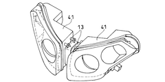
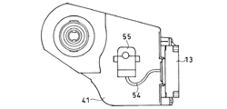
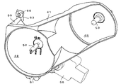
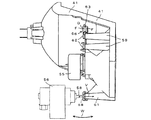
次に、前記放電灯52の点灯制御について説明する。図5はヘッドライト40のリフレクタ41の斜視図であり、図6は車両左側に設けられるヘッドライト40の背面図である。両図において、左右一対のリフレクタ41,41の間には、それぞれにバラスト13,13が設けられている。バラスト13はトランスを有しているため、比較的重量が大きいが、このように、2つのヘッドライトの中間に設けたために、安定感がある。
【0022】
このバラスト13および放電灯52の接続には、ノイズ対策がとられた高圧シールド線54が用いられているが、同様に、ノイズ対策として放電灯52のソケットはリフレクタ41に直接結合されており、ソケットにはさらにソケットカバー55が被せられている。
【0023】
図7はバラスト13のハード構成を示すブロック図であり、図8はこのバラストによって制御された放電灯52への印加電圧を示す図である。図7において、バラスト13は昇圧部131および起動部132、ならびに昇圧部131および起動部132に制御信号を供給する制御部133からなる。昇圧部131はDC12ボルトの電源に接続されており、起動部132は放電灯52つまりメタルハライド電球に接続されている。
【0024】
図8において、起動部132を付勢して、昇圧部131で昇圧された電圧(例えば400ボルトで0.25秒間)を放電灯52に印加すると、キセノン発光が起こる。キセノン発光から予定時間(例えば0.5秒)経過後に、起動時よりは低圧の交流(例えば電圧80ボルト400ヘルツ)を印加し、水銀蒸気およびメタルハライド中でアークを持続させて定常状態を形成する。
【0025】
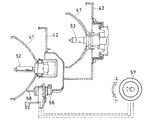
続いて、ヘッドライト40の光軸調節(エーミング)機構ついて説明する。本実施形態のヘッドライトは運転者の操作によって光軸を上下に調節できる機構を有している。図9はエーミング機構の概念を示す模式図である。同図に示すように、ヘッドライト40のケース42にはエーミング用のモータ56が固定されていて、調節つまみ57を上方向または下方向に回すと、この回動量に応じてモータ56が回転しシャフト58が往復動する。シャフト58はリフレクタ41の背面部に係合しており、リフレクタ41はシャフト58の動きに従動して上下方向に角度を変える。その結果、リフレクタ41に取付けられている放電灯52およびハロゲンランプ53の光軸が上下する。次に、具体的な構造を説明する。
【0026】
図10は左側ヘッドライトのリフレクタ41の同背面斜視図、図11は前面斜視図、図12は同側面図である。これらの図において、リフレクタ41のリフレクタ面48の背面には3か所に2本1組のステム59,60,61が形成されている。そして、それぞれのステム59,60,61の端部には止めねじ62を用いてアタッチメント金具63,64,65が取付けられている。アタッチメント金具63,64,65にはゴム等の弾性材料からなるブッシュ66,67,68が嵌合されている。ブッシュ66等は、図12から理解できるように胴Dと胴Dの両端に形成された鍔Fとを有し、この胴Dがアタッチメント金具63等に形成された溝に嵌まり、鍔Fがアタッチメント金具63の両面に当接している。
【0027】
ブッシュ66,67はリフレクタ41を後方から覆っている前記カバー42に保持され、ブッシュ66,67の胴Dの中心を結ぶ直線69が光軸調節のための矢印W方向の枢軸動作の軸になる。一方、ブッシュ68にはモータ56のシャフト58が係合し、ブッシュ68はこのシャフト58の動きに従って矢印V方向に前後動する。上記シャフト58の動きにより、リフレクタ41は直線69を枢軸として回動し、光軸が上下方向に調節される。
【0028】
このように、ロービーム側のリフレクタ面48に光軸調節の枢軸(直線69)を配置することによって、特に、ロービームの照射精度が高められる。運転者が必要とする範囲に強い発光を行う放電管を光源としたロービームを正確に照射するためである。
【0029】
【発明の効果】
以上の説明から明らかなように、請求項1〜請求項3の発明によれば、ロービームおよびハイビームのそれぞれに適した配光を行うことができる。特に、ロービームおよびハイビームはそれぞれ異なる高さから照射されるので、ロービームおよびハイビームの切替時に、高いアクセント効果が得られる。また、請求項2の発明によれば、広い配光を要求されるロービームに適した発光を得ることができる。また、請求項3の発明によれば、各組の灯具間つまり車両の中央寄りでロービーム用灯具に近接して放電管用昇圧装置を配置したので、ノイズ対策が容易であり、かつ放電管用昇圧装置を車両上に重量バランス良く配置できる。
【0030】
さらに、請求項4および請求項5の発明によれば、容易に光軸調節を行うことができ、特に、強い発光を伴うロービームの光軸を正確に調節することができる。
【図面の簡単な説明】
【図1】 本発明の一実施形態に係る前照灯装置の正面図である。
【図2】 本発明の一実施形態に係る前照灯装置の側面断面図である。
【図3】 本発明の一実施形態に係る前照灯装置の平面図である。
【図4】 本発明の一実施形態に係る前照灯装置を搭載した自動二輪車の外観を示す側面図である。
【図5】 本発明の一実施形態に係る前照灯装置のリフレクタの斜視図である。
【図6】 本発明の一実施形態に係る前照灯装置のリフレクタの背面図である。
【図7】 放電灯の昇圧装置のハード構成を示すブロック図である。
【図8】 昇圧装置で制御された放電灯への印加電圧を示す図である。
【図9】 エーミング機構の概念を示す模式図である。
【図10】 リフレクタの背面斜視図である。
【図11】 リフレクタの正面斜視図である。
【図12】 リフレクタの側面図である。
【符号の説明】
1…車両、 2…エンジン、 10…メータユニット、 11…カウル、 12…レンス面、 13…昇圧装置、 14…風防スクリーン、 40…ヘッドライト、 41…リフレクタ、 42…カバー、 48…ロービーム側リフレクタ面、 49…ハイビーム側リフレクタ面、 52…放電灯、 53…ハロゲンランプ[0001]
BACKGROUND OF THE INVENTION
The present invention relates to a vehicle headlamp device, and more particularly to a vehicle headlamp device suitable for enhancing the light distribution suitable for both low beam and high beam and the accent effect on appearance.
[0002]
[Prior art]
A vehicle having a cowling on the front and a four-lamp headlight (headlight) supported on the cowling is known. Of the four-lamp headlights, two lights in the center are for low beams, and the two lights on the left and right are for high beams. By the way, the cowling is provided for the purpose of reducing the resistance of the air received at the front of the vehicle during high speed driving and improving the traveling performance. However, if four lamps are arranged on the left and right, the width of the cowling increases, so the air resistance It is disadvantageous in terms of mitigation, and it is inferior in aesthetics. In particular, when obtaining a sufficient amount of light, the diameter of the reflector increases and the width further increases.
[0003]
Therefore, in order to eliminate such problems, by adopting a projector-type headlight that projects the light reflected by the reflecting mirror through the convex lens and projects it forward, the reflector is reduced and the width of the cowling is reduced. A proposed motorcycle has been proposed (Japanese Patent Laid-Open No. 2-136383).
[0004]
[Problems to be solved by the invention]
The conventional headlight has an appearance accent because the light emission position changes between the low beam and the high beam. However, since all four lights are the same type of light source, the accent effect is weak. Furthermore, there is a problem that it is difficult to obtain light distribution characteristics suitable for each of the low beam and the high beam. That is, the low beam needs to irradiate a relatively short distance over a wide range, and the high beam is required to be able to irradiate a long distance in a spot manner, but such characteristics are difficult to obtain with a conventional headlight.
[0005]
In addition, since the projector-type headlight has a long lamp, there is a problem that the layout of components such as instruments installed behind the headlight is limited. Yes.
[0006]
The present invention solves the above-mentioned problems, enhances the accent effect when switching between the low beam and the high beam, makes it possible to make the light distribution characteristics appropriate, and increase the degree of freedom in the layout behind the headlights. An object is to provide a lighting device.
[0007]
[Means for Solving the Problems]
In order to achieve the above object, the present invention provides a vehicle headlamp device in which one set of a low beam lamp and a high beam lamp are arranged on the left and right sides of the front of the vehicle, respectively. A low beam lamp is arranged closer to the vehicle, a high beam lamp is arranged higher than the low beam lamp closer to the side of the vehicle, and the reflector surface of the low beam lamp is more than the reflector surface of the high beam lamp. The first feature is that the lens surface that is set large and covers each pair of lamps is set to gradually decrease from the low beam lamp side to the high beam lamp side in correspondence with each reflector surface. There is. Further, the present invention has a second feature in that the light source of the low beam lamp is a discharge tube. Furthermore, the present invention has a third feature in that each discharge tube booster is disposed between the lamps of each set.
[0008]
According to the first feature, the low beam is reflected by a large reflector surface and irradiates a wide range in front, and the high beam is reflected by a small reflector surface and irradiates the far distance as spot light. Further, since the high beam and the low beam are irradiated from different heights, the accent effect when switching between the high beam and the low beam is great. In particular, according to the second feature, unlike a halogen lamp or the like, the discharge tube emits light strongly, so that a wide light distribution suitable as a low beam is possible. Further, according to the third feature, since the discharge tube boosting device is disposed at a position close to the discharge tube, the high-voltage shield line that needs noise countermeasures can be shortened, and noise prevention can be performed more effectively. Furthermore, it is a preferable arrangement in terms of balance by positioning the discharge tube booster at the center of the vehicle.
[0009]
Further, the present invention includes a reflector in which reflector surfaces of the low beam lamp and the high beam lamp are integrally formed, and includes an adjusting means for rotating the reflector up and down for optical axis adjustment, and the reflector. A fourth feature is that the rotation center axis is set with respect to the reflector surface of the low beam lamp so that the optical axis of the low beam lamp can be adjusted as desired. Furthermore, the present invention has a fifth feature in that the adjusting means includes an electric motor, and the electric motor rotates the reflector up and down.
[0010]
According to the 4th characteristic, the low beam which has strong light emission can be correctly irradiated to the direction suitable for a driving | operation. In particular, according to the fifth feature, since the optical axis can be adjusted electrically, the burden on the driver can be reduced and accurate adjustment is possible.
[0011]
DETAILED DESCRIPTION OF THE INVENTION
The present invention will be described below with reference to the drawings. In the following description, the same or equivalent parts are denoted by the same reference numerals. FIG. 4 is a side view showing the appearance of a motorcycle equipped with a headlight according to an embodiment of the present invention. In the figure, a motorcycle (hereinafter referred to as a “vehicle”) 1 is equipped with a horizontally opposed 6-
[0012]
A
[0013]
A
[0014]
An
[0015]
Note that the lower side of the
[0016]
Next, the front structure of the vehicle will be described. 1 is a front view of the main part of the vehicle, FIG. 2 is a side sectional view thereof, FIG. 3 is a plan view thereof, and the same reference numerals as those in FIG. These drawings show only the left half of the vehicle. A
[0017]
A
[0018]
As shown in FIG. 1, the
[0019]
Therefore, in accordance with the
[0020]
The relatively
[0021]
Next, lighting control of the
[0022]
The
[0023]
FIG. 7 is a block diagram showing a hardware configuration of the
[0024]
In FIG. 8, when the starter 132 is energized and a voltage boosted by the booster 131 (eg, 400 volts for 0.25 seconds) is applied to the
[0025]
Next, the optical axis adjustment (aiming) mechanism of the
[0026]
10 is a rear perspective view of the
[0027]
The
[0028]
In this manner, by arranging the pivot axis (straight line 69) for adjusting the optical axis on the
[0029]
【The invention's effect】
As is clear from the above description, according to the inventions of
[0030]
Further, according to the inventions of
[Brief description of the drawings]
FIG. 1 is a front view of a headlamp device according to an embodiment of the present invention.
FIG. 2 is a side sectional view of a headlamp device according to an embodiment of the present invention.
FIG. 3 is a plan view of a headlamp device according to an embodiment of the present invention.
FIG. 4 is a side view showing an appearance of a motorcycle equipped with a headlamp device according to an embodiment of the present invention.
FIG. 5 is a perspective view of a reflector of the headlamp device according to the embodiment of the present invention.
FIG. 6 is a rear view of the reflector of the headlamp device according to the embodiment of the present invention.
FIG. 7 is a block diagram showing a hardware configuration of a booster device for a discharge lamp.
FIG. 8 is a diagram showing a voltage applied to a discharge lamp controlled by a booster.
FIG. 9 is a schematic diagram showing a concept of an aiming mechanism.
FIG. 10 is a rear perspective view of the reflector.
FIG. 11 is a front perspective view of a reflector.
FIG. 12 is a side view of the reflector.
[Explanation of symbols]
DESCRIPTION OF
Claims (8)
前記各組の灯具のうち車両中央寄りにはロービーム用灯具を配置し、車両側部寄りには前記ロービーム用灯具よりも高位置にハイビーム用灯具を配置するとともに、
前記ロービーム用灯具のリフレクタ面を前記ハイビーム用灯具のリフレクタ面よりも大きく設定し、
かつ、各組の灯具を覆うレンズ面は、前記各リフレクタ面に対応して、ロービーム用灯具側からハイビーム用灯具側へ漸次小さくなるように設定していることを特徴とする自動二輪車用前照灯装置。In a motorcycle headlamp device in which a pair of low beam lamps and high beam lamps are symmetrically arranged on the left and right sides of the front part of the vehicle,
A low beam lamp is arranged near the center of the vehicle among each set of lamps, and a high beam lamp is arranged at a position higher than the low beam lamp near the vehicle side,
The reflector surface of the low beam lamp is set larger than the reflector surface of the high beam lamp,
And a lens surface that covers each set of the lamp, the corresponding to each reflector surface, it irradiation before a motorcycle, characterized in that set to become gradually smaller to the high beam lamp side from the low-beam lamp side Lamp device.
前記リフレクタの回動中心軸を前記ロービーム用灯具の光軸を所望に調節できるように該ロービーム用灯具のリフレクタ面に関して設定したことを特徴とする請求項1〜請求項3のいずれかに記載の自動二輪車用前照灯装置。A reflector having integrally formed reflector surfaces of the low beam lamp and the high beam lamp, and provided with an adjusting means for rotating the reflector up and down for optical axis adjustment;
4. The rotating central axis of the reflector is set with respect to the reflector surface of the low beam lamp so that the optical axis of the low beam lamp can be adjusted as desired. Motorcycle headlamp device.
前記各組の灯具のうち車両中央寄りには放電ランプで構成されたロービーム用灯具を配置し、車両側部寄りには前記ロービーム用灯具よりも高位置にハイビーム用灯具を配置するとともに、
前記ロービーム用灯具は、前記ハイビーム用灯具よりも前方に配置され、
かつ、各組の灯具を覆うレンズ面は、前記ロービーム灯具および前記ハイビーム用灯具の位置に対応して、車両側部寄りで後方に退いた後傾配置になっていることを特徴とする自動二輪車用前照灯装置。In a motorcycle headlamp device in which a pair of low beam lamps and high beam lamps are symmetrically arranged on the left and right sides of the front part of the vehicle,
A low beam lamp composed of a discharge lamp is arranged near the center of the vehicle in each set of lamps, and a high beam lamp is arranged at a position higher than the low beam lamp near the vehicle side,
The low beam lamp is arranged in front of the high beam lamp,
In addition, the motorcycle has a lens surface that covers each set of lamps, and is rearwardly tilted so as to recede toward the side of the vehicle, corresponding to the position of the low beam lamp and the high beam lamp. Headlamp device.
前記レンズ面のロービーム用灯具および前記ハイビーム用灯具に対応する部分は、前記リフレクタの大きさに対応して互いに大きさが異なっていることを特徴とする請求項6記載の自動二輪車用前照灯装置The sizes of the reflector surfaces of the low beam lamp and the high beam lamp are different from each other,
7. The motorcycle headlamp according to claim 6, wherein portions of the lens surface corresponding to the low beam lamp and the high beam lamp are different in size according to the size of the reflector. apparatus
前記各組の灯具のうち車両中央寄りにはロービーム用灯具を配置し、車両側部寄りには前記ロービーム用灯具よりも高位置にハイビーム用灯具を配置するとともに、 A low beam lamp is arranged near the center of the vehicle among each set of lamps, and a high beam lamp is arranged at a position higher than the low beam lamp near the vehicle side,
前記ロービーム用灯具のリフレクタ面を前記ハイビーム用灯具のリフレクタ面よりも大きく設定し、The reflector surface of the low beam lamp is set larger than the reflector surface of the high beam lamp,
かつ、各組の灯具を覆うレンズ面は、前記各リフレクタ面に対応して、ロービーム用灯具側からハイビーム用灯具側へ漸次小さくなるように設定し、And, the lens surface covering each set of lamps is set so as to gradually decrease from the low beam lamp side to the high beam lamp side corresponding to each of the reflector surfaces,
前記ロービーム用灯具の光源が放電管であり、The light source of the low beam lamp is a discharge tube,
前記各組の灯具間にそれぞれの放電管用昇圧装置を配置したことを特徴とする車両用前照灯装置。A vehicular headlamp device, characterized in that a discharge tube booster is disposed between the lamps of each set.
Priority Applications (3)
| Application Number | Priority Date | Filing Date | Title |
|---|---|---|---|
| JP09143299A JP4333887B2 (en) | 1999-03-31 | 1999-03-31 | Vehicle headlamp device |
| DE10012896A DE10012896B4 (en) | 1999-03-31 | 2000-03-16 | Headlamp unit for a vehicle |
| US09/539,715 US6439753B1 (en) | 1999-03-31 | 2000-03-31 | Headlight unit for a vehicle |
Applications Claiming Priority (1)
| Application Number | Priority Date | Filing Date | Title |
|---|---|---|---|
| JP09143299A JP4333887B2 (en) | 1999-03-31 | 1999-03-31 | Vehicle headlamp device |
Publications (3)
| Publication Number | Publication Date |
|---|---|
| JP2000280946A JP2000280946A (en) | 2000-10-10 |
| JP2000280946A5 JP2000280946A5 (en) | 2006-04-20 |
| JP4333887B2 true JP4333887B2 (en) | 2009-09-16 |
Family
ID=14026219
Family Applications (1)
| Application Number | Title | Priority Date | Filing Date |
|---|---|---|---|
| JP09143299A Expired - Lifetime JP4333887B2 (en) | 1999-03-31 | 1999-03-31 | Vehicle headlamp device |
Country Status (3)
| Country | Link |
|---|---|
| US (1) | US6439753B1 (en) |
| JP (1) | JP4333887B2 (en) |
| DE (1) | DE10012896B4 (en) |
Families Citing this family (34)
| Publication number | Priority date | Publication date | Assignee | Title |
|---|---|---|---|---|
| JP3907941B2 (en) | 2000-12-14 | 2007-04-18 | 株式会社小糸製作所 | Automotive headlamps |
| US20050099818A1 (en) * | 2001-01-19 | 2005-05-12 | Stephan Gropp | Headlight unit for single-track two-wheeled vehicles |
| US7445364B2 (en) * | 2001-01-19 | 2008-11-04 | Stephan Gropp | Headlight unit for single-track two-wheeled vehicles |
| US20030123255A1 (en) * | 2001-10-30 | 2003-07-03 | Randy Marchetti | Lamp assembly with dual mode reflector |
| JP3988466B2 (en) * | 2002-01-17 | 2007-10-10 | スズキ株式会社 | Two-light headlight device for motorcycles |
| DE10209589B4 (en) * | 2002-03-05 | 2010-01-28 | Volkswagen Ag | Headlight assembly of a vehicle |
| US6729750B2 (en) * | 2002-06-18 | 2004-05-04 | Arctic Cat, Inc. | Brake lever dimmer switch |
| JP4168713B2 (en) * | 2002-09-13 | 2008-10-22 | スズキ株式会社 | Front structure of motorcycle |
| US20040246732A1 (en) * | 2003-06-05 | 2004-12-09 | Lewis Chad J. | Self-adjusting motorcycle headlight |
| US7080929B2 (en) * | 2004-07-29 | 2006-07-25 | Kawasaki Jukogyo Kabushika Kaisha | Lamp unit in motorcycle |
| JP4417230B2 (en) * | 2004-11-24 | 2010-02-17 | 本田技研工業株式会社 | Vehicle lighting system |
| JP4796364B2 (en) * | 2005-09-15 | 2011-10-19 | 川崎重工業株式会社 | VEHICLE LAMP DEVICE AND MOTORCYCLE HAVING THE SAME |
| JP4674757B2 (en) * | 2005-10-31 | 2011-04-20 | 本田技研工業株式会社 | Headlight support structure |
| JP2007283927A (en) * | 2006-04-18 | 2007-11-01 | Yamaha Motor Co Ltd | Motorcycle |
| US7527440B1 (en) | 2006-06-05 | 2009-05-05 | White Osborn L | Triangular vehicle light apparatus with camera |
| DE602007010564D1 (en) * | 2006-09-29 | 2010-12-30 | Honda Motor Co Ltd | Support structure for a lighting unit |
| US8035305B2 (en) * | 2007-12-19 | 2011-10-11 | Buell Motorcycle Company | Alternating headlights and method of operating |
| JP5061358B2 (en) * | 2008-01-31 | 2012-10-31 | 株式会社小糸製作所 | Motorcycle headlights |
| JP5239052B2 (en) * | 2008-02-26 | 2013-07-17 | 本田技研工業株式会社 | Light vehicle headlight |
| CN102089199B (en) * | 2008-03-28 | 2013-05-22 | 雅马哈发动机株式会社 | Straddle riding-type vehicle |
| JP5190309B2 (en) * | 2008-06-30 | 2013-04-24 | 本田技研工業株式会社 | Motorcycle headlight structure |
| CN101825251A (en) * | 2009-03-02 | 2010-09-08 | 光阳工业股份有限公司 | Headlight device of motorcycle |
| US9518711B2 (en) * | 2011-09-27 | 2016-12-13 | Truck-Lite Co., Llc | Modular headlamp assembly |
| JP5941810B2 (en) * | 2012-09-28 | 2016-06-29 | 本田技研工業株式会社 | Front cowl structure for saddle riding type vehicles |
| JP6026879B2 (en) * | 2012-12-14 | 2016-11-16 | 川崎重工業株式会社 | Motorcycle headlamp device |
| JP6104675B2 (en) | 2013-03-29 | 2017-03-29 | 本田技研工業株式会社 | Motorcycle headlight device |
| JP6190611B2 (en) * | 2013-03-29 | 2017-08-30 | 本田技研工業株式会社 | Motorcycle headlight device |
| US9944340B2 (en) * | 2013-10-10 | 2018-04-17 | Honda Motor Co., Ltd. | LED headlight structure for motorcycle |
| JP6537779B2 (en) * | 2014-03-31 | 2019-07-03 | 本田技研工業株式会社 | Vehicle lighting equipment |
| CN104848135A (en) * | 2015-06-02 | 2015-08-19 | 江苏远洋车灯有限公司 | Automobile front combined lamp |
| JP6844955B2 (en) * | 2016-05-10 | 2021-03-17 | 川崎重工業株式会社 | Headlamp device for vehicles |
| JP6739991B2 (en) * | 2016-05-10 | 2020-08-12 | 川崎重工業株式会社 | Headlamp device for saddle type vehicles |
| DE102016121104B4 (en) * | 2016-11-04 | 2023-02-09 | Ledlenser GmbH & Co. KG | Bicycle light with two light sources, each of which illuminates a segment of a reflector for the far range and for the close range |
| WO2019150391A1 (en) * | 2018-02-02 | 2019-08-08 | Varroc Engineering Private Limited | Automobile headlight assembly |
Family Cites Families (13)
| Publication number | Priority date | Publication date | Assignee | Title |
|---|---|---|---|---|
| US3099400A (en) * | 1962-02-19 | 1963-07-30 | Lucas C Holmes | Dual headlights for motorcycles |
| JPS6055593U (en) * | 1983-09-26 | 1985-04-18 | 本田技研工業株式会社 | Motorcycle headlight device |
| JPH02136383A (en) * | 1988-11-17 | 1990-05-24 | Yamaha Motor Co Ltd | Motorcycle |
| DE3844269A1 (en) * | 1988-12-30 | 1990-07-05 | Bosch Gmbh Robert | HEADLIGHTS FOR MOTOR VEHICLES |
| US5117335A (en) * | 1989-12-28 | 1992-05-26 | Koito Manufacturing Co., Ltd. | Headlight for vehicle |
| JP2769259B2 (en) * | 1992-01-27 | 1998-06-25 | 株式会社小糸製作所 | Automotive headlamp |
| JPH06103801A (en) * | 1992-09-21 | 1994-04-15 | Yamaha Motor Co Ltd | Headlamp device of motorcycle |
| DE4238274C2 (en) * | 1992-11-13 | 1999-04-01 | Bosch Gmbh Robert | Multi-range reflector as part of a motor vehicle headlight |
| JP3493611B2 (en) * | 1993-12-29 | 2004-02-03 | 本田技研工業株式会社 | Headlights for motorcycles |
| JP2878111B2 (en) * | 1994-03-09 | 1999-04-05 | 株式会社小糸製作所 | Vehicle lighting |
| JP3193603B2 (en) * | 1995-12-25 | 2001-07-30 | 株式会社小糸製作所 | Vehicle headlights |
| JP3825108B2 (en) * | 1996-11-18 | 2006-09-20 | 本田技研工業株式会社 | Motorcycle headlights |
| JP3866383B2 (en) * | 1997-07-30 | 2007-01-10 | 本田技研工業株式会社 | Motorcycle headlamp device |
-
1999
- 1999-03-31 JP JP09143299A patent/JP4333887B2/en not_active Expired - Lifetime
-
2000
- 2000-03-16 DE DE10012896A patent/DE10012896B4/en not_active Expired - Fee Related
- 2000-03-31 US US09/539,715 patent/US6439753B1/en not_active Expired - Lifetime
Also Published As
| Publication number | Publication date |
|---|---|
| JP2000280946A (en) | 2000-10-10 |
| DE10012896A1 (en) | 2000-10-05 |
| US6439753B1 (en) | 2002-08-27 |
| DE10012896B4 (en) | 2007-12-13 |
Similar Documents
| Publication | Publication Date | Title |
|---|---|---|
| JP4333887B2 (en) | Vehicle headlamp device | |
| JP3964101B2 (en) | Vehicle headlamp | |
| JP3061248B2 (en) | Automotive headlamp | |
| JP3939529B2 (en) | Vehicle headlamp | |
| JP4094847B2 (en) | Motorcycle headlights | |
| TW470714B (en) | Headlight of motorcycle | |
| JP2001236802A (en) | Vehicle headlight | |
| JP3335228B2 (en) | Vehicle headlights | |
| JP2965930B2 (en) | Vehicle headlights | |
| JP6975844B2 (en) | Cornering lights for saddle-mounted vehicles | |
| CN205417342U (en) | Far and near light auto -change over device of car light | |
| JP4853913B2 (en) | Motorcycle headlamp device | |
| JP2001250407A (en) | Vehicle headlamp | |
| JP4438571B2 (en) | Motorcycle headlamp device | |
| JP4594566B2 (en) | Motorcycle lamp unit | |
| JP3158882B2 (en) | Automotive lighting | |
| JP3447451B2 (en) | Motorcycle headlights | |
| JP3481026B2 (en) | Motorcycle headlights | |
| JP4545325B2 (en) | Motorcycle headlight device | |
| JPH11238405A (en) | Head lamp device for vehicle | |
| JP2001063655A (en) | Lighting apparatus fitting construction in compact vehicle | |
| JP4300789B2 (en) | Motorcycle headlamp device | |
| JP4435435B2 (en) | Variable light distribution headlamp | |
| JP2000062665A (en) | Body front part structure of motorcycle | |
| JP2817603B2 (en) | Auxiliary lighting device |
Legal Events
| Date | Code | Title | Description |
|---|---|---|---|
| A521 | Request for written amendment filed |
Free format text: JAPANESE INTERMEDIATE CODE: A523 Effective date: 20060302 |
|
| A621 | Written request for application examination |
Free format text: JAPANESE INTERMEDIATE CODE: A621 Effective date: 20060302 |
|
| A977 | Report on retrieval |
Free format text: JAPANESE INTERMEDIATE CODE: A971007 Effective date: 20081016 |
|
| A131 | Notification of reasons for refusal |
Free format text: JAPANESE INTERMEDIATE CODE: A131 Effective date: 20081029 |
|
| A521 | Request for written amendment filed |
Free format text: JAPANESE INTERMEDIATE CODE: A523 Effective date: 20081219 |
|
| TRDD | Decision of grant or rejection written | ||
| A01 | Written decision to grant a patent or to grant a registration (utility model) |
Free format text: JAPANESE INTERMEDIATE CODE: A01 Effective date: 20090617 |
|
| A01 | Written decision to grant a patent or to grant a registration (utility model) |
Free format text: JAPANESE INTERMEDIATE CODE: A01 |
|
| A61 | First payment of annual fees (during grant procedure) |
Free format text: JAPANESE INTERMEDIATE CODE: A61 Effective date: 20090618 |
|
| FPAY | Renewal fee payment (event date is renewal date of database) |
Free format text: PAYMENT UNTIL: 20120703 Year of fee payment: 3 |
|
| R150 | Certificate of patent or registration of utility model |
Free format text: JAPANESE INTERMEDIATE CODE: R150 |
|
| FPAY | Renewal fee payment (event date is renewal date of database) |
Free format text: PAYMENT UNTIL: 20120703 Year of fee payment: 3 |
|
| FPAY | Renewal fee payment (event date is renewal date of database) |
Free format text: PAYMENT UNTIL: 20130703 Year of fee payment: 4 |
|
| FPAY | Renewal fee payment (event date is renewal date of database) |
Free format text: PAYMENT UNTIL: 20140703 Year of fee payment: 5 |
|
| EXPY | Cancellation because of completion of term |
