JP4333542B2 - ICP emission analyzer - Google Patents
ICP emission analyzer Download PDFInfo
- Publication number
- JP4333542B2 JP4333542B2 JP2004288846A JP2004288846A JP4333542B2 JP 4333542 B2 JP4333542 B2 JP 4333542B2 JP 2004288846 A JP2004288846 A JP 2004288846A JP 2004288846 A JP2004288846 A JP 2004288846A JP 4333542 B2 JP4333542 B2 JP 4333542B2
- Authority
- JP
- Japan
- Prior art keywords
- plasma
- plasma flame
- plasma torch
- optical system
- cone
- Prior art date
- Legal status (The legal status is an assumption and is not a legal conclusion. Google has not performed a legal analysis and makes no representation as to the accuracy of the status listed.)
- Expired - Fee Related
Links
Images


Description
本発明は、ICP(高周波誘導結合プラズマ)発光分析に関する。 The present invention relates to ICP (High Frequency Inductively Coupled Plasma) emission analysis.
ICP発光分析装置においては、液体試料はネブライザーで霧化され試料エアロゾルとなり、アルゴンガスと共にプラズマトーチに導入される。プラズマトーチの先端部外周を誘導コイルが囲繞しており、この誘導コイルに供給される高周波電流によって、プラズマトーチ先端にアルゴンプラズマ炎が生成される。試料エアロゾル中の試料原子は、このプラズマ炎を通過する時に加熱・励起されて、原子種固有の波長の発光を呈する。この発光を分光分析することにより、試料中の元素の定性・定量測定が行われる。 In the ICP emission analyzer, a liquid sample is atomized by a nebulizer to form a sample aerosol, which is introduced into a plasma torch together with argon gas. An induction coil surrounds the outer periphery of the tip of the plasma torch, and an argon plasma flame is generated at the tip of the plasma torch by the high frequency current supplied to the induction coil. The sample atoms in the sample aerosol are heated and excited when passing through the plasma flame, and emit light having a wavelength unique to the atomic species. By performing spectroscopic analysis of this luminescence, qualitative and quantitative measurement of elements in the sample is performed.
従来用いられているプラズマトーチおよびスプレーチェンバーとネブライザーの一構成例を図5に示す。図5において、プラズマトーチAは同軸円筒状の三重構造になっており、内芯には試料エアロゾルを含むキャリアガス(アルゴンガス)を通すキャリアガス管5が位置し、その周囲をプラズマ用のアルゴンガスを流すためのプラズマガス管4が、さらに最外周を冷却用のアルゴンガスを流すためのクーラントガス管3が取り囲む構造になっている。そして、クーラントガス管3の端部外側に高周波誘導電流を流すコイル2が2〜3ターン巻きつけられている。(特許文献1参照)
FIG. 5 shows a configuration example of a plasma torch, a spray chamber and a nebulizer that are conventionally used. In FIG. 5, the plasma torch A has a coaxial cylindrical triple structure, and a carrier gas pipe 5 through which a carrier gas (argon gas) containing a sample aerosol is passed is located in the inner core, and the surrounding area is argon for plasma. The plasma gas pipe 4 for flowing gas is configured to further surround the coolant gas pipe 3 for flowing argon gas for cooling on the outermost periphery. And the
キャリアガス管5に試料エアロゾルを供給するためのスプレーチェンバー8には、図5のようにネブライザー7が気密に挿着されており、ネブライザー7を通じてキャリアガスが供給される。ネブライザー7は細管によって試料9に繋がっており、キャリアガスがネブライザー7先端より噴出する際に生じる負圧によって、霧吹きの原理で試料9が吸い上げられ、微細な霧となってスプレーチェンバー8内に噴出する。スプレーチェンバー8の下部にはレベラー14が設けられており、霧化された試料9の中の粗い霧滴はレベラー14を通じて外部に排出される。レベラー14は同時に、その中に滞留する排出液によってキャリアガスの流出を封止し、さらに、排出液の液面のレベルを一定に保持することにより、液面の変動に起因する測定信号の揺らぎを防止する。
A nebulizer 7 is hermetically inserted in the
測定時には、コイル2に高周波電流が供給されて、プラズマトーチAの先端部に高温のプラズマ炎1が形成される。試料9は、スプレーチェンバー8内でエアロゾル化し、キャリアガスと混合されてプラズマトーチAのキャリアガス管5を通過し、最後にプラズマ炎1の中心に送り込まれる。エアロゾル中の試料原子は、プラズマ炎1内で加熱・励起され、発光する。この発光は、プラズマ炎1の側方におかれた分光器(図5には示されていない)の入口スリット上に、レンズあるいはミラーを用いた集光光学系によって集光される。
At the time of measurement, a high frequency current is supplied to the
上記のような、発光をプラズマ炎1の側方から観測する方法の他に、発光をプラズマ炎1の中心軸方向から観測する方法が最近広く採用されている。この場合には、図6に示すような2種類の配置が一般的である。図6の(b)の例では、プラズマトーチAは垂直に置かれ、プラズマ炎1の上方に設けられたミラー22を介して、プラズマ炎1の軸方向の発光が集光レンズ17により分光器に集光される。一方、図6の(a)の例では、プラズマトーチAは水平に配置され、プラズマ炎1の軸方向の発光が集光レンズ17により直接分光器に集光される。また、同一装置で、プラズマ炎の側方観察と軸方観察を、複数のミラーによって切り替える方法も使用されている。(特許文献2参照)
従来のICP発光分析装置におけるプラズマトーチAおよびスプレーチェンバー8は、上記のように構成されているが、これには以下に述べる問題点がある。
The plasma torch A and the
前述のように、従来のプラズマトーチを使用するためには複数の光学素子を配置する必要があり、このため、測定前の光学系の微調整が不可欠となっている。特にプラズマ炎の最大発光点が集光光学系の焦点に正確に位置するように調節することが重要であり、通常は、測定者がプラズマトーチの位置の微調節を測定前に毎回行っている。このため複雑な位置微調節機構が必要となり、装置の製造コストを引き上げると共に、調整作業が煩雑になる欠点がある。また、複雑な光学系のため、測定光強度が分光器到達前に減殺される問題点もある。 As described above, in order to use the conventional plasma torch, it is necessary to arrange a plurality of optical elements. For this reason, fine adjustment of the optical system before measurement is indispensable. In particular, it is important to adjust the maximum emission point of the plasma flame so that it is accurately positioned at the focal point of the condensing optical system. Usually, the measurer fine-tunes the position of the plasma torch before each measurement. . For this reason, a complicated position fine adjustment mechanism is required, which increases the manufacturing cost of the apparatus and makes the adjustment work complicated. In addition, because of the complicated optical system, there is a problem that the measurement light intensity is reduced before reaching the spectroscope.
また、噴出するプラズマ炎と周囲のアルゴンガス(パージガス)との間の大きな温度差と流速の差によって、プラズマ炎と周辺空気との境界およびその近傍は強い乱流状態となる。プラズマ炎の側方あるいはプラズマ炎の進行方向から発光を観測する従来のICP発光分析装置では、被測定光が上記の乱流領域を通過する際に受ける擾乱のために、測定信号中に精度を低下させるノイズが混入する可能性がある。 Further, due to a large temperature difference and a flow velocity difference between the plasma flame to be ejected and the surrounding argon gas (purge gas), the boundary between the plasma flame and the surrounding air and its vicinity become a strong turbulent state. In a conventional ICP emission spectrometer that observes light emission from the side of the plasma flame or from the direction of travel of the plasma flame, the accuracy of the measurement signal is increased due to the disturbance that the measured light undergoes when passing through the turbulent flow region. Noise to reduce may be mixed.
さらに、従来のICP発光分析装置では、プラズマトーチAとスプレーチェンバー8およびレベラー14がそれぞれ別個に設けられ、互いに適当な材質及び形状の配管系で接続されているが、これらの部分が装置上で大きな体積を占め、装置全体の小型化の障害となっている。また、スプレーチェンバー8からプラズマ炎1までのエアロゾルの流路行程が比較的長いために、プラズマトーチAとスプレーチェンバー8の連結部あるいはプラズマトーチA内部でエアロゾルが再凝縮することがあり、再凝縮で生じた液滴がキャリアガスの流れを乱す、あるいは極端な場合、キャリアガスの流路を詰まらせる危険がある。特に図6の(a)のように、プラズマトーチAを水平に配置した場合には、再凝縮で生じた液滴がレベラー14から排出されることが困難であるため、上記の危険がさらに大きくなる。
Further, in the conventional ICP emission spectrometer, the plasma torch A, the
本発明は、上記の様な問題点に鑑みてなされたもので、複雑な光学系を必要とせず、従って、複雑な調節機構と調節作業が不要であり、プラズマ炎周辺の乱流の影響を受けず、しかも、プラズマトーチとスプレーチェンバーを効率的に融合・一体化させたICP発光分析装置を提供することを目的とする。 The present invention has been made in view of the above problems, and does not require a complicated optical system. Therefore, a complicated adjustment mechanism and adjustment work are unnecessary, and the influence of turbulent flow around the plasma flame is reduced. In addition, an object of the present invention is to provide an ICP emission analysis apparatus in which a plasma torch and a spray chamber are efficiently fused and integrated.
上記の目的を達成するために、本発明のICP発光分析装置では、プラズマトーチを同軸多重管とし、この一方の端部にプラズマ炎を形成させ、前記多重管プラズマトーチの他端方向よりプラズマトーチの中心を介して、前記プラズマ炎の発光を観測できる光学系を設ける。これによって測定時に於ける上記プラズマトーチあるいは集光光学系の光学的相対位置の微調節作業を不要とすると共に、プラズマ炎の周辺四方側面と頂部方向を他の目的のために利用できるようにする。さらに、上記プラズマトーチの多重管を同軸多層の円錐管とし、その内部にスプレーチェンバーとレベラーを一体的に包設する。さらに、上記プラズマトーチの円錐面と平行に巻かれた、円錐状の高周波誘導電流コイルを備えていることを特徴とする。 In order to achieve the above object, in the ICP emission spectrometer of the present invention, the plasma torch is a coaxial multi-tube, a plasma flame is formed at one end thereof, and the plasma torch from the other end of the multi-tube plasma torch is formed. An optical system capable of observing the light emission of the plasma flame is provided through the center of. This eliminates the need for fine adjustment work of the optical relative position of the plasma torch or the focusing optical system during measurement, and makes it possible to use the peripheral four sides and the top direction of the plasma flame for other purposes. . Further, the multiple tube of the plasma torch is a coaxial multilayer conical tube, and a spray chamber and a leveler are integrally wrapped therein. Further, the plasma torch includes a conical high-frequency induction current coil wound in parallel with the conical surface of the plasma torch.
本発明によって、測定前の光学系の微調整作業が不要となり、調節機構および光学素子の数を低減でき、装置コストの低減が可能となる。また、プラズマ炎をプラズマトーチの底部方向より観察することにより、プラズマ炎周辺のアルゴンガス(パージガス)の乱れによるノイズを軽減できる。また、スプレーチェンバーとレベラーをプラズマトーチと一体化することにより、装置の小形化が可能となる。また、ネブライザー7先端からプラズマ炎1までの距離が短くなり、エアロゾルの水滴化が軽減される。さらに、コイルを円錐形に形成することにより、高感度化が期待できる。さらに、プラズマ炎の周囲を開放することにより、例えば、ICP発光分析装置と、ICP質量分析装置とでプラズマ炎を共有し、両者の同時分析が可能となる。 According to the present invention, the fine adjustment work of the optical system before the measurement becomes unnecessary, the number of adjusting mechanisms and optical elements can be reduced, and the apparatus cost can be reduced. Further, by observing the plasma flame from the bottom direction of the plasma torch, noise due to the disturbance of the argon gas (purge gas) around the plasma flame can be reduced. Further, the apparatus can be miniaturized by integrating the spray chamber and the leveler with the plasma torch. Further, the distance from the tip of the nebulizer 7 to the plasma flame 1 is shortened, and aerosolization of aerosol is reduced. Furthermore, high sensitivity can be expected by forming the coil in a conical shape. Further, by opening the periphery of the plasma flame, for example, the ICP emission analyzer and the ICP mass spectrometer can share the plasma flame, and both can be analyzed simultaneously.
本発明のICP発光分析装置についての最良の形態は、プラズマトーチを同軸多重管とし、この一方の端部にプラズマ炎を形成させ、前記多重管プラズマトーチの他端方向よりプラズマトーチの中心を介して、前記プラズマ炎の発光を観測できる光学系を設ける。さらに、上記プラズマトーチの多重管を同軸多層の円錐管とし、その内部にスプレーチェンバーとレベラーを一体的に包設し、上記プラズマトーチの円錐面と平行に巻かれた、円錐状の高周波誘導電流コイルを備え、装置全体が小型、コンパクトになっているものである。 The best mode of the ICP emission analyzer of the present invention is that the plasma torch is a coaxial multi-tube, and a plasma flame is formed at one end of the plasma torch via the center of the plasma torch from the other end of the multi-tube plasma torch. And an optical system capable of observing the light emission of the plasma flame. Further, the plasma torch multi-tube is a coaxial multilayer conical tube, in which a spray chamber and a leveler are integrally wrapped, and a conical high frequency induction current wound in parallel with the conical surface of the plasma torch. A coil is provided, and the entire apparatus is small and compact.
本発明の一実施形態を、図1、図2、および図3に従って説明する。
図1は、本発明に係るプラズマトーチを分光器に取り付けたときの外観図であり、図2はプラズマトーチの中心軸を含む縦断面を示す図であり、さらに図3はプラズマトーチの円筒形基台部をプラズマトーチの軸芯に垂直な面で切断した断面を示す図である。これらの図において、プラズマトーチAは、外観上は、円筒形の基台部Dと、それに連続する円錐部分で構成されている。円筒形の基台部Dには、プラズマトーチAにガスを供給する3箇所のガス供給口(クーラントガス入口11、プラズマガス入口12、パージガス入口13)が設けられており、図では省略されているが、それぞれフレキシブルな管でICP発光分析装置のガス流量制御装置に接続される。また、後述するように、プラズマトーチAにはスプレーチェンバー8が内設されており、この中に被測定試料を霧化して供給するためのネブライザー7が着脱自在に挿着されている。ネブライザー7のキャリアガス供給口24と試料導入口23もまた、フレキシブルな管によってそれぞれガス流量制御部と試料容器に接続される。また、図1のLはレベラーで、基台部Dに一体的に付設されている。このレベラーLからの排出液は、適当な管によって廃液槽へ導出される。プラズマトーチAは、固定具20によって分光器Bに定着されている。ただし、固定具20の形状および個数は本実施例に限定されるものではない。また、プラズマトーチAの円錐部の頂点近傍にはコイル2が配設されている。ICP発光分析装置の電源からコイル2に高周波誘導電流が供給され、プラズマトーチAに所定の流量のアルゴンガスが供給されると、プラズマトーチAの円錐端の前方に高温のプラズマ炎1が発生する。
One embodiment of the present invention will be described with reference to FIGS. 1, 2, and 3.
FIG. 1 is an external view when the plasma torch according to the present invention is attached to a spectrometer, FIG. 2 is a view showing a longitudinal section including the central axis of the plasma torch, and FIG. 3 is a cylindrical shape of the plasma torch. It is a figure which shows the cross section which cut | disconnected the base part by the surface perpendicular | vertical to the axial center of a plasma torch. In these drawings, the plasma torch A is configured with a cylindrical base D and a conical portion continuous therewith in appearance. The cylindrical base D is provided with three gas supply ports (a
プラズマトーチAは、図2に示すように4層の同軸円錐管で構成されている。第一層(最外層)のクーラントガス管3内部にはクーラントガスが、クーラントガス入口11を通じて供給される。第二層のプラズマガス管4内部にはプラズマガスが、プラズマガス入口12を通じて供給される。第三層のキャリアガス管5と第4層のパージガス管6の間隙には、スプレーチェンバー8の空腔を介してネブライザー7から試料のエアロゾルを含むキャリアガスが供給される。第四層(最内層)のパージガス管6内部にはパージガスが、パージガス入口13を通じて供給される。
As shown in FIG. 2, the plasma torch A is composed of four layers of coaxial conical tubes. The coolant gas is supplied through the
プラズマトーチAは、パージガスの外部漏洩あるいは外部空気の侵入を防止するためのOリング21と共に、固定具20によって分光器Bに固着される。また、コイル2がプラズマトーチAの円錐部先端近傍に位置するよう固定されている。本実施例に於いては、コイル2はプラズマトーチAの円錐面に平行な円錐形に形成されている。プラズマ炎1は図2に示すような位置に形成される。プラズマトーチAが固定具20によって分光器Bに固着されたとき、プラズマトーチAの中心軸が分光器Bの集光光学系の光軸に一致し、さらに、プラズマ炎1の最大発光点が分光器Bの集光光学系の焦点に合致するように、プラズマトーチA、および分光器Bと固定具20があらかじめ設計・加工されている。本実施例では、集光光学系として集光レンズ17が使用されており、上記集光レンズ17の焦点18が、プラズマ炎1の最大発光位置に合致する。
The plasma torch A is fixed to the spectroscope B by a fixture 20 together with an O-ring 21 for preventing the purge gas from leaking outside or the outside air from entering. Further, the
前述のように、本発明のプラズマトーチAにはスプレーチェンバー8が内設されている。図2に示すように、スプレーチェンバー8は、キャリアガス管5とパージガス管6の間隙が円錐底部で拡張した、比較的広い空間で形成されており、この内部にネブライザー7がその先端部を挿入されている。以下に図3によってその内部構造を詳説する。図3は、図2におけるS−S′断面を、円錐底部より頂部に向かって視た図である。スプレーチェンバー8は、プラズマトーチAの外壁とパージガス管6に挟まれた概略円環状の空腔で、その上部にはネブライザー7が気密に挿着されている。ネブライザー7の中心部細管の一端(試料導入口23)には、試料容器から繋がるフレキシブルな細管(図3では省略)が接続され、これより試料が供給される。ネブライザー7に開設された側管(キャリアガス供給口24)には、ガス流量制御部よりキャリアガスが供給される。一方、スプレーチェンバー8から、パージガス管6とキャリアガス管5の間隙に向けて開孔15が開設されており、図2で示すようにスプレーチェンバー8の空腔は、開孔15を通してパージガス管6とキャリアガス管5の間隙を経由してプラズマ炎1に繋がる。
As described above, the
ネブライザー7先端より噴出するキャリアガスと共に、霧化された試料がスプレーチェンバー8内に噴出する。十分微細なエアロゾルがキャリアガスとスプレーチェンバー8内で混合されて、開孔15を通じてプラズマ炎1に供給される。粗い霧滴およびスプレーチェンバー8内で再凝集した液滴は、図3に示すようにスプレーチェンバー8下部に集積し、レベラーLを通して外部へ排出される。通気孔10は、レベラーL内の液面上部空間を大気圧に保つために開設されており、排出液がレベラーLからサイフォンの原理で急激に流出して液面レベルを急変させる現象を防止する。また、キャリアガス管5への液滴の流入が、キャリアガス流の不安定化、その結果としてプラズマ炎1の不安定化を惹起することを防止するため、開孔15はキャリアガス管5とパージガス管6の間隙全域ではなく、図3に示すように、間隙の下部の、180゜より小さな角度θの範囲に限定されている。
The atomized sample is ejected into the
以上のように構成されている本発明に係るICP発光分析装置を用いて分析を行う場合には、ICP発光分析装置のガス流量制御部によってそれぞれ最適流量に設定された四系統のアルゴンガス(クーラントガス、プラズマガス、キャリアガス、パージガス)がプラズマトーチAに供給されると共に、ICP発光分析装置電源部より高周波誘導電流がコイル2に供給され、プラズマ炎1が形成される。試料はキャリアガスの働きでネブライザー7を介してスプレーチェンバー8内に噴霧される。霧化した試料はスプレーチェンバー8内でキャリアガスと混合したエアロゾルとなり、キャリアガスによってプラズマ炎1の中心部に送給される。エアロゾル中の被測定元素はプラズマ炎1内でプラズマ炎1の熱によって励起され発光する。プラズマ炎1を発した光は、図2の矢印で示すように集光レンズ17によって分光器入口スリット19上に集光される。その後は、分光器BおよびICP発光分析装置の測光部の働きによって分光分析が行われる。
When the analysis is performed using the ICP emission analyzer according to the present invention configured as described above, four systems of argon gas (coolant) each set to an optimum flow rate by the gas flow rate control unit of the ICP emission analyzer. Gas, plasma gas, carrier gas, and purge gas) are supplied to the plasma torch A, and a high frequency induction current is supplied to the
上記分析操作において、プラズマトーチAの形状および寸法が、分光器Bに固着された状態で、プラズマ炎1の最大発光点が集光光学系の光軸上にあり、また集光光学系の焦点18がプラズマ炎1の最大発光点と合致していることが保証されているため、きわめて感度の高い分析が可能となり、さらに、分析前の煩雑な光学系およびプラズマトーチAの位置の微調節が不要となる。また、複雑な微調節機構や余分なミラーやレンズなどの光学素子が不要となり、装置の製造コストの軽減が可能となると共に、光学素子による光量低下を最小限に抑えることができる。 In the above analysis operation, the shape and dimensions of the plasma torch A are fixed to the spectrometer B, the maximum emission point of the plasma flame 1 is on the optical axis of the condensing optical system, and the focal point of the condensing optical system. 18 is guaranteed to match the maximum emission point of the plasma flame 1, so that highly sensitive analysis is possible, and further, the complicated optical system before analysis and the fine adjustment of the position of the plasma torch A are possible. It becomes unnecessary. In addition, a complicated fine adjustment mechanism and an extra optical element such as an extra mirror or lens are not required, so that the manufacturing cost of the apparatus can be reduced, and a decrease in light amount due to the optical element can be minimized.
本実施例において、コイル2は円錐形に形成されている。これによって、プラズマ炎1の外縁部への膨張が抑制され、その結果、発光強度分布が中心軸近傍に絞り込まれるため、測定感度が向上することが期待できる。
In this embodiment, the
また、光が通るプラズマトーチAの内芯部はパージガス管6に囲繞されており、パージガスが定常的に流れているため、光路中への空気の混入がない。一般の例に従い分光器B内を真空にすれば、光路全域に亘って酸素の吸収による光量損失の無い、高感度の分析が可能となる。さらに、プラズマ炎1の根底部から発光を採取し、層流に近い状態のガス空間を通して集光するため、従来技術で問題となるアルゴンガス(パージガス)の激しい乱流による測光信号へのノイズの混入が最小限に抑えられる。 Further, the inner core portion of the plasma torch A through which light passes is surrounded by the purge gas pipe 6, and since the purge gas flows constantly, there is no mixing of air into the optical path. If the inside of the spectroscope B is evacuated according to a general example, it is possible to perform highly sensitive analysis without loss of light amount due to absorption of oxygen over the entire optical path. Furthermore, since light emission is collected from the bottom of the plasma flame 1 and collected through a gas space in a state close to laminar flow, noise in the photometric signal due to intense turbulence of argon gas (purge gas), which is a problem in the prior art, is reduced. Contamination is minimized.
さらに、本発明に係るプラズマトーチAは、その内部にスプレーチェンバー8およびレベラーLを一体として包設している。これにより、装置全体の小形化が可能となる。また、スプレーチェンバー8からプラズマ炎1に至るまでのキャリアガスの流路行程が図6に示した従来技術における行程より短縮されているため、プラズマトーチA内でエアロゾルが冷却されて再凝縮する危険性が軽減されると共に、プラズマトーチA内でのキャリアガス流路の断面積が従来技術におけるより大きいため、再凝縮で生じた液滴が流路を詰まらせる危険性も、大幅に低減されている。また、スプレーチェンバー8からプラズマ炎1へ向けてキャリアガスを送出する開孔15が、キャリアガス管5の全周に亘らず、下方の部分にのみ開設されている。これにより試料液滴が開孔15からキャリアガス管5に流入することを最小限に防止できると共に、万一液滴が流入しても、キャリアガス管5あるいはパージガス管6の壁面が開孔15の近傍ではスプレーチェンバー8の方向に降斜しているため、液滴がプラズマ炎1の方向に流出する危険が最小限に抑えられている。
Furthermore, the plasma torch A according to the present invention has the
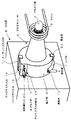
本発明に係るプラズマトーチAによって形成されるプラズマ炎1は、その周辺領域が開放されている。この特徴を有効に利用する一例が図4に示されている。この例においては、本発明に係るICP発光分析装置Cのプラズマ炎1に、併置されたICP質量分析装置Cのサンプリングコーン22を対向させ、プラズマ炎1の先端よりサンプリングコーン22を介して、プラズマ炎1によってイオン化された気体をICP質量分析装置Cに採取し分析を行うものである。図4のように構成された装置では、同一装置で、ICP発光分析とICP質量分析の双方が実施可能となる。本発明における特徴は、上述したとおりであるが、上記ならびに図示例に限定されるものではなく、種々の変形例を含む。たとえば、光学系としては、レンズ系によらずミラー系あるいは光ファイバーを利用する光学系も含まれる。
The plasma flame 1 formed by the plasma torch A according to the present invention has an open peripheral area. An example of effectively utilizing this feature is shown in FIG. In this example, the
本発明は、ICP(高周波誘導結合プラズマ)発光分析に関する。 The present invention relates to ICP (High Frequency Inductively Coupled Plasma) emission analysis.
A…プラズマトーチ
B…分光器
C…ICP質量分析装置
1…プラズマ炎
2…コイル
3…クーラントガス管
4…プラズマガス管
5…キャリアガス管
6…パージガス管
7…ネブライザー
8…スプレーチェンバー
9…試料
D…基台部
10…通気孔
11…クーラントガス入口
12…プラズマガス入口
13…パージガス入口
14…レベラー
L…レベラー
15…開孔
17…集光レンズ
18…焦点
19…分光器入口スリット
20…固定具
21…Oリング
22…サンプリングコーン
23…試料導入口
24…キャリアガス供給口
A ... plasma torch B ... spectrometer C ... ICP mass spectrometer 1 ...
Claims (3)
Priority Applications (1)
| Application Number | Priority Date | Filing Date | Title |
|---|---|---|---|
| JP2004288846A JP4333542B2 (en) | 2004-09-30 | 2004-09-30 | ICP emission analyzer |
Applications Claiming Priority (1)
| Application Number | Priority Date | Filing Date | Title |
|---|---|---|---|
| JP2004288846A JP4333542B2 (en) | 2004-09-30 | 2004-09-30 | ICP emission analyzer |
Publications (2)
| Publication Number | Publication Date |
|---|---|
| JP2006105616A JP2006105616A (en) | 2006-04-20 |
| JP4333542B2 true JP4333542B2 (en) | 2009-09-16 |
Family
ID=36375553
Family Applications (1)
| Application Number | Title | Priority Date | Filing Date |
|---|---|---|---|
| JP2004288846A Expired - Fee Related JP4333542B2 (en) | 2004-09-30 | 2004-09-30 | ICP emission analyzer |
Country Status (1)
| Country | Link |
|---|---|
| JP (1) | JP4333542B2 (en) |
Cited By (2)
| Publication number | Priority date | Publication date | Assignee | Title |
|---|---|---|---|---|
| US10815552B2 (en) | 2013-06-19 | 2020-10-27 | Rio Tinto Alcan International Limited | Aluminum alloy composition with improved elevated temperature mechanical properties |
| US11579092B2 (en) * | 2020-04-23 | 2023-02-14 | Sumco Corporation | Sample introduction device, inductively coupled plasma analyzing device and analyzing method |
-
2004
- 2004-09-30 JP JP2004288846A patent/JP4333542B2/en not_active Expired - Fee Related
Cited By (2)
| Publication number | Priority date | Publication date | Assignee | Title |
|---|---|---|---|---|
| US10815552B2 (en) | 2013-06-19 | 2020-10-27 | Rio Tinto Alcan International Limited | Aluminum alloy composition with improved elevated temperature mechanical properties |
| US11579092B2 (en) * | 2020-04-23 | 2023-02-14 | Sumco Corporation | Sample introduction device, inductively coupled plasma analyzing device and analyzing method |
Also Published As
| Publication number | Publication date |
|---|---|
| JP2006105616A (en) | 2006-04-20 |
Similar Documents
| Publication | Publication Date | Title |
|---|---|---|
| US9541479B2 (en) | Apparatus and method for liquid sample introduction | |
| US9804183B2 (en) | Apparatus and method for liquid sample introduction | |
| JP5841601B2 (en) | An improved discharge box for optical emission spectrometry. | |
| US6989529B2 (en) | Plasma torch | |
| CN105074419B (en) | Laser for composition analysis system degrades unit and flare system | |
| US5012065A (en) | Inductively coupled plasma torch with laminar flow cooling | |
| JP5965743B2 (en) | ICP device, spectroscopic analyzer, and mass spectrometer | |
| KR20210083268A (en) | Optical particle sensors, especially exhaust gas sensors | |
| JP4779807B2 (en) | ICP emission spectrometer | |
| JP4333542B2 (en) | ICP emission analyzer | |
| US6709632B2 (en) | ICP analyzer | |
| US6122050A (en) | Optical interface for a radially viewed inductively coupled argon plasma-Optical emission spectrometer | |
| JP2010197080A (en) | Induction coupling plasma analyzer | |
| McLean et al. | Fundamental properties of aerosols produced in helium by a direct injection nebulizer | |
| JP2007078460A (en) | Icp atomic emission spectrometer | |
| JP2014190958A (en) | Icp emission spectrophotometer | |
| JP2009121846A (en) | Sample liquid feed pump, and icp emission spectrometer using liquid feed pump | |
| JP2724541B2 (en) | ICP emission spectrometer | |
| US5731872A (en) | Plasma manipulator | |
| JP2001305059A (en) | Inductively coupled plasma photometric analyzer and its method | |
| JP2003240718A (en) | Icp emission spectrometric apparatus | |
| JP2018179555A (en) | Emission spectrometer | |
| SG182967A1 (en) | Collimator arrangements including multiple, collimators and implementation methods thereof | |
| JP2000074839A (en) | Ipc spectral analyzing device with protecting gas release port | |
| JPH09166545A (en) | Atomic absorption analyzing device |
Legal Events
| Date | Code | Title | Description |
|---|---|---|---|
| A621 | Written request for application examination |
Free format text: JAPANESE INTERMEDIATE CODE: A621 Effective date: 20070125 |
|
| A977 | Report on retrieval |
Free format text: JAPANESE INTERMEDIATE CODE: A971007 Effective date: 20080919 |
|
| A131 | Notification of reasons for refusal |
Free format text: JAPANESE INTERMEDIATE CODE: A131 Effective date: 20080930 |
|
| A521 | Written amendment |
Free format text: JAPANESE INTERMEDIATE CODE: A523 Effective date: 20081127 |
|
| A131 | Notification of reasons for refusal |
Free format text: JAPANESE INTERMEDIATE CODE: A131 Effective date: 20090310 |
|
| A521 | Written amendment |
Free format text: JAPANESE INTERMEDIATE CODE: A523 Effective date: 20090508 |
|
| TRDD | Decision of grant or rejection written | ||
| A01 | Written decision to grant a patent or to grant a registration (utility model) |
Free format text: JAPANESE INTERMEDIATE CODE: A01 Effective date: 20090602 |
|
| A01 | Written decision to grant a patent or to grant a registration (utility model) |
Free format text: JAPANESE INTERMEDIATE CODE: A01 |
|
| A61 | First payment of annual fees (during grant procedure) |
Free format text: JAPANESE INTERMEDIATE CODE: A61 Effective date: 20090615 |
|
| FPAY | Renewal fee payment (event date is renewal date of database) |
Free format text: PAYMENT UNTIL: 20120703 Year of fee payment: 3 |
|
| FPAY | Renewal fee payment (event date is renewal date of database) |
Free format text: PAYMENT UNTIL: 20120703 Year of fee payment: 3 |
|
| FPAY | Renewal fee payment (event date is renewal date of database) |
Free format text: PAYMENT UNTIL: 20120703 Year of fee payment: 3 |
|
| FPAY | Renewal fee payment (event date is renewal date of database) |
Free format text: PAYMENT UNTIL: 20130703 Year of fee payment: 4 |
|
| LAPS | Cancellation because of no payment of annual fees |