JP4333459B2 - Image forming system - Google Patents
Image forming system Download PDFInfo
- Publication number
- JP4333459B2 JP4333459B2 JP2004121234A JP2004121234A JP4333459B2 JP 4333459 B2 JP4333459 B2 JP 4333459B2 JP 2004121234 A JP2004121234 A JP 2004121234A JP 2004121234 A JP2004121234 A JP 2004121234A JP 4333459 B2 JP4333459 B2 JP 4333459B2
- Authority
- JP
- Japan
- Prior art keywords
- sheet
- processing
- paper
- image forming
- unit
- Prior art date
- Legal status (The legal status is an assumption and is not a legal conclusion. Google has not performed a legal analysis and makes no representation as to the accuracy of the status listed.)
- Expired - Fee Related
Links
Images


Description
本発明は、画像形成装置本体で記録された記録済みの用紙に対して種々の後処理を可能とする画像形成システムに関し、特に、複数の後処理装置の中から選択的に所望の1種類以上の後処理装置を画像形成装置本体に装着可能にする画像形成システムに関する。 The present invention relates to an image forming system that enables various post-processing on recorded paper recorded by an image forming apparatus main body, and in particular, desired one or more types selectively from a plurality of post-processing apparatuses. concerning the post-processing apparatus to the image forming system that can be mounted to the image forming apparatus main body.
従来、画像形成装置としての複写機に、画像記録後の用紙を穿孔処理、綴じ止め処理、折り処理する機能を有する後処理機を装着可能とする画像形成システムがある(例えば、特許文献1参照)。 2. Description of the Related Art Conventionally, there is an image forming system in which a copying machine as an image forming apparatus can be mounted with a post-processing machine having functions of punching paper, binding paper, and folding paper after recording an image (for example, see Patent Document 1). ).
かかる画像形成システムの場合、種々の後処理機能が1つの後処理機で対応可能に構成されているため、例えばオフィス等のように、様々なユーザーが様々な使い方をする環境に設置される場合に有効である。また、係る後処理機は比較的コンパクトであるため、省スペース化が求められるオフィス等には、その点でも有効である。 In the case of such an image forming system, since various post-processing functions are configured to be supported by one post-processing machine, the system is installed in an environment where various users use in various ways such as an office. It is effective for. In addition, since such a post-processing machine is relatively compact, it is also effective in this respect for offices and the like that require space saving.
また、例えば軽印刷等のシステムとして用いる場合には、あらゆる後処理機能を満足させられるシステムである必要は必ずしもなく、ある特定の後処理機能のみが十分に満足できる性能を満たしたシステムであることが求められる。即ち、軽印刷等のシステムとして用いる場合は、オフィスで用いられる場合のように、様々のユーザーによって様々な使い方がなされるよりも、特定のユーザーが特定の後処理機能のみを使う頻度の方が高い。 In addition, when used as a system for light printing, for example, it is not necessarily a system that can satisfy all post-processing functions, and only a specific post-processing function must satisfy sufficient performance. Is required. In other words, when used as a system for light printing, the frequency with which a specific user uses only a specific post-processing function is greater than that used by various users as in an office. high.
しかしながら、前述の画像形成システムは、1つの比較的コンパクトな後処理機で種々の後処理機能を有して様々な使用形態に対応可能にしているが、個々の後処理機能に特化して着目すると、機能的に必ずしも十分なレベルであるとは言えない。例えば、画像形成システムを軽印刷等のシステムとして用いる場合には、オフィス等で用いられる画像形成システムに求められる後処理機能のレベルよりも高く、それを十分に満足させられるレベルには達していない。 However, the image forming system described above has a variety of post-processing functions with a single relatively compact post-processing machine and can be used in various forms of use. This is not necessarily a functionally sufficient level. For example, when the image forming system is used as a system for light printing or the like, it is higher than the level of a post-processing function required for an image forming system used in an office or the like and does not reach a level that can sufficiently satisfy it. .
また、最近では、電子写真方式の画像形成装置が軽印刷の分野に使用されるようになってきた。即ち、前述のような後処理機を備えた画像形成システムを用いる事により、「必要なときに必要な部数だけプリントを行う」プリントオンデマンド方式の製本が可能になる。 Recently, an electrophotographic image forming apparatus has been used in the field of light printing. That is, by using the image forming system including the post-processing machine as described above, it is possible to perform a print-on-demand bookbinding that “prints as many copies as necessary when necessary”.
しかも、従来の印刷で行われていた印刷版起しの手間もないので、製本作業の効率アップと、コストダウンに大きな期待が寄せられている。 Moreover, since there is no need to raise a printing plate, which has been performed in conventional printing, great expectations are placed on the efficiency of bookbinding and cost reduction.
ところで、軽印刷用のシステムで要求される後処理機能は、ある特定の機能が安定かつ確実に作動することであり、オフィス向けのシステムのような多種類の機能を同時に満足するものとは異なるものである。したがって、オフィス向けに設計された後処理機能を有する画像形成システムを軽印刷分野で使用すると、軽印刷で要求されるレベルの性能を有していないため、却って製本作業の効率を低下させる要因となった。 By the way, the post-processing function required in the system for light printing is that a specific function operates stably and reliably, and is different from the one that satisfies various functions at the same time as the system for offices. Is. Therefore, if an image forming system with post-processing functions designed for offices is used in the light printing field, it does not have the level of performance required for light printing. became.
このような事情から軽印刷分野で要求される性能をクリアーする後処理機能を搭載した画像形成システムが検討され、例えば、特定の後処理機能に特化できるように後処理機能をユニット化してシステム構築させたものが検討されたが、システムの大型化を招いた。システムの大型化は、経営規模の小さな業者の多い軽印刷の分野では、普及の足かせとなるものであった。また、後処理機を特定の処理機能に特化できるようにする事は、部品点数を増大させるになり、メンテナンス性の面からも好ましいものではなかった。
本発明は上述のような問題点を解決し、画像形成システムの小型化および部品点数の削減によるコストダウンを図るとともに、それぞれの後処理機能の性能が十分に高く、またジャム発生時のジャム処理性の高い画像形成システムを提供する事を目的とするものである。 The present invention solves the problems as described above, along with reduce cost by reducing the size and number of parts of the image forming system, the performance of each post-processing function is sufficiently rather high, also when a jam jamming Another object of the present invention is to provide a high has image forming system of processability.
上記の目的は、本発明の下記の画像形成システムよって達成される。 The above object is achieved by the following image forming system of the present invention.
(1) 画像形成装置本体と、複数種類の後処理機とを有する画像形成システムにおいて、
前記後処理機の中の1つである単シート処理機が、他の後処理機を介することなく前記画像形成装置本体に対して装着されており、さらに前記単シート処理機の用紙搬送方向下流側に他の後処理機が装着されており、
前記単シート処理機は、1枚毎に用紙を後処理する複数種類の単シート処理機能、および、出力される用紙束にカバー用紙またはインサート用紙を付加する用紙付加機能を有しており、
前記複数種類の後処理機の全てが、ジャム発生時に画像形成システム内に残留した残留用紙、または、画像記録状態を確認するための試し記録済みの用紙が排出される排出部を有することを特徴とする画像形成システム。
これにより、ジャム発生時に画像形成システム内に残留した残留用紙を、それぞれの排出部に排出可能なため、各残留用紙を用紙の搬送方向下流側の最も近い位置の排出部にそれぞれ排出することが可能となり、ジャム処理性が高まる。
また、全枚数を記録する前に一枚だけ試し記録した用紙を、何れかの排出部に排出するように構成することにより、何れかの後処理機の位置で記録状態を確認可能である。
なお、各排出部は、各後処理機によって後処理された用紙が排出される通常の排出部とは異なるものである。また、各排出部は、ジャム発生時に残留用紙が排出される排出部としての機能と、試し記録済みの用紙が排出される排出部としての機能の何れか一方または両方の機能を満たす排出部である。
(1) In an image forming system having an image forming apparatus main body and a plurality of types of post-processing machines,
A single sheet processing machine, which is one of the post-processing machines, is mounted on the image forming apparatus main body without passing through another post-processing machine, and is further downstream in the sheet conveying direction of the single sheet processing machine. other post-processing device is mounted on the side,
The single sheet processing machine, a plurality of types of single-sheet processing function of post-processing the sheets one by one, and has have a sheet additional function of adding the cover sheet or the insert sheet to the sheet bundle to be output,
All of the plurality of types of post-processing machines include a discharge unit that discharges residual paper remaining in the image forming system when a jam occurs or a test-recorded paper for confirming an image recording state. An image forming system.
As a result, the remaining sheets remaining in the image forming system when a jam occurs can be discharged to the respective discharge sections, so that each remaining sheet can be discharged to the discharge section closest to the downstream side in the sheet conveyance direction. This makes it possible to increase the jam handling ability.
In addition, the recording state can be confirmed at any position of the post-processing device by configuring so that only one sheet of paper that has been trial-recorded before recording the total number of sheets is discharged to one of the discharge units.
Note that each discharge unit is different from a normal discharge unit that discharges paper that has been post-processed by each post-processing machine. Each discharge unit is a discharge unit that fulfills one or both of the function of a discharge unit that discharges residual paper when a jam occurs and the function of a discharge unit that discharges test-recorded paper. is there.
(2) 前記画像形成システムが1枚毎に用紙を後処理する複数種類の単シート処理機能を備えており、前記複数種類の単シート処理機能の全てを前記単シート処理機が備えることを特徴とする前記(1)に記載の画像形成システム。 (2) pre-Symbol comprises a plurality of types of single-sheet processing functions of the image forming system to post-processing the sheets one by one, that comprises all of the plurality of types of single-sheet processing functions said single sheet processing machine The image forming system according to (1), characterized in that
これによって、画像形成システム全体として、さらなる小型化が可能である。 As a result, the image forming system as a whole can be further reduced in size.
(3) 前記単シート処理機能が、1枚毎に用紙を穿孔処理するパンチ機能、1枚毎に用紙を折り処理する折り機能、1枚毎に用紙にミシン目を形成するミシン目機能、1枚毎に用紙を断裁する単シート断裁機能の何れかであることを特徴とする前記(1)または(2)に記載の画像形成システム。 (3) The single sheet processing function includes a punch function for punching a sheet for each sheet, a folding function for folding a sheet for each sheet, a perforation function for forming a perforation on each sheet, The image forming system according to (1) or (2), wherein the image forming system is any one of a single sheet cutting function for cutting a sheet for each sheet.
これにより、単シート処理機にパンチ機能、折り機能、ミシン目機能、単シート断裁機能のうち、少なくとも2つの単シート処理を行うことが可能である。 Thereby, it is possible to perform at least two single sheet processing among the punch function, the folding function, the perforation function, and the single sheet cutting function in the single sheet processing machine.
(4) 前記単シート処理機が、前記画像形成装置本体から搬送される用紙を受け入れる単シート処理搬入部と、他の何れかの後処理機に向けて用紙を搬出する単シート処理搬出部とを有することを特徴とする前記(1)〜(3)の何れか1項に記載の画像形成システム。 (4) A single sheet processing carry-in unit that receives the paper conveyed from the image forming apparatus main body, and a single sheet processing carry-out unit that carries out the paper toward any other post-processing device. the image forming system according to any one of the above (1) to (3), characterized in that have a.
これにより、単シート処理機が画像形成装置本体に装着され、それ以外の後処理機を、適宜、単シート処理機よりも用紙の搬送方向下流側に配置できるため、単シート処理がなされた用紙に対しても他の後処理機による種々の後処理を行うことが可能である。 Accordingly, the single sheet processing machine is mounted on the image forming apparatus main body, and other post-processing machines can be appropriately disposed downstream of the single sheet processing machine in the paper transport direction. However, it is possible to perform various post-processing by other post-processing machines.
(5) 前記単シート処理機が、1枚毎に用紙を穿孔処理するパンチ処理部と、前記パンチ処理部に対して用紙搬送方向下流側に配置され、1枚毎に用紙を折り処理する折り処理部とを有することを特徴とする前記(1)〜(4)の何れか1項に記載の画像形成システム。 (5) The single sheet processing machine is disposed on the downstream side in the sheet conveyance direction with respect to the punch processing unit for punching a sheet for each sheet, and the sheet is folded for each sheet. The image forming system according to any one of (1) to (4), further including a processing unit.
これにより、折り処理前の用紙に対して穿孔処理を行えるため、用紙に対する穿孔位置の精度を高められる。即ち、折り処理時に用紙に対して全く傾斜のない折り目を形成することは困難であるため、折り処理後の用紙に対して穿孔処理する場合、例えば折り目を基準にして位置合わせして穿孔処理すると、用紙に対する折り目の傾斜に伴い、用紙に対する穿孔位置が傾斜することが多かった。本構成により、用紙に対する折り目の傾斜に関わりなく、傾斜のない位置精度の高い穿孔が可能である。 Thereby, since the punching process can be performed on the sheet before the folding process, the accuracy of the punching position with respect to the sheet can be improved. That is, since it is difficult to form a crease that is not inclined at all with respect to the sheet during the folding process, for example, when punching a sheet after folding, it is necessary to perform the punching process by aligning with respect to the fold. In many cases, the perforation position with respect to the sheet is inclined with the inclination of the fold with respect to the sheet. With this configuration, it is possible to perform perforation with high positional accuracy without inclination regardless of the inclination of the fold with respect to the sheet.
(6) 前記単シート処理機が、前記画像形成装置本体から搬送される用紙を受け入れる単シート処理搬入部と、他の何れかの後処理機に向けて用紙を搬出する単シート処理搬出部と、1枚毎に用紙を後処理する第1処理部と、前記第1処理部に対して用紙搬送方向下流側に配置され、1枚毎に用紙を後処理する第2処理部と、前記単シート処理搬入部で受け入れた用紙を前記第1処理部および前記第2処理部を介することなく、前記単シート処理搬出部まで搬送するための第1搬送路と、前記単シート処理搬入部で受け入れた用紙を前記第1処理部に搬送するための第2搬送路と、前記第1処理部から前記第2処理部に用紙を搬送するための第3搬送路と、前記第2処理部から前記第1搬送路に用紙を搬送するための第4搬送路と、を有することを特徴とする前記(1)〜(5)の何れか1項に記載に画像形成システム。 (6) A single sheet processing carry-in unit that receives the paper conveyed from the image forming apparatus main body, and a single sheet processing carry-out unit that carries out the paper toward any other post-processing device. A first processing unit that post-processes the paper for each sheet; a second processing unit that is disposed downstream of the first processing unit in the paper transport direction; A first transport path for transporting the sheet received by the sheet processing carry-in unit to the single sheet processing carry-out unit without passing through the first processing unit and the second processing unit, and the single sheet processing carry-in unit. A second transport path for transporting the paper to the first processing section, a third transport path for transporting the paper from the first processing section to the second processing section, and the second processing section to the above-mentioned A fourth transport path for transporting paper to the first transport path The image forming system according to any one of (1) to (5), characterized in that.
これにより、単シート処理搬入部で受け入れられた用紙は、何れかの処理部で後処理するかしないかに関わらず、第1搬送路に戻されて単シート処理搬出部まで搬送される。よって、他の後処理機を選択的に装着可能な画像形成システムにおいて、単シート処理搬入部に用紙を送り込む画像形成装置本体や他の後処理機側の用紙搬出経路や、単シート処理搬出部から用紙が送り込まれる他の後処理機側の用紙搬入経路を簡素化できる。 As a result, the sheet received by the single sheet processing carry-in section is returned to the first transport path and conveyed to the single sheet processing carry-out section regardless of whether or not post-processing is performed by any processing section. Therefore, in an image forming system in which other post-processing machines can be selectively mounted, the image forming apparatus main body that feeds paper to the single sheet processing carry-in section, the paper carry-out path on the other post-processing machine side, and the single sheet processing carry-out section Therefore, it is possible to simplify the paper carry-in route on the other post-processing machine side where the paper is fed from.
(7) 前記単シート処理機の前記第3搬送路が、用紙の搬送方向の長さが所定長さ以下の用紙を前記第2処理部に搬送するための第3A搬送路と、用紙の搬送方向の長さが前記所定長さよりも大きい用紙を前記第2処理部に搬送するための第3B搬送路とを有することを特徴とする前記(6)に記載の画像形成システム。 (7) The third conveyance path of the single sheet processing machine includes a third A conveyance path for conveying a sheet whose length in the sheet conveyance direction is a predetermined length or less to the second processing unit, and conveyance of the sheet. The image forming system according to (6), further including a third B conveyance path for conveying a sheet having a direction length larger than the predetermined length to the second processing unit.
これにより、第3A搬送路を第2処理部までのショートカット経路として設け、用紙の搬送方向の長さに応じて第3A搬送路と第3B搬送路とを使い分けることが可能になるため、搬送方向の長さが所定長さ以下の用紙の場合に、後処理の生産性が高まる。 Accordingly, the 3A conveyance path is provided as a shortcut path to the second processing unit, and the 3A conveyance path and the 3B conveyance path can be selectively used according to the length of the sheet conveyance direction. When the length of the paper is a predetermined length or less, the post-processing productivity is increased.
なお、第3A搬送路と第3B搬送路との使い分けは、例えば、画像形成装置本体に設けられた操作パネルから入力された情報を基に、第2搬送路と第3A搬送路との分岐点に設けられたフラッパーの向きを制御して、何れかの搬送路側に用紙を送り込むようにする。 Note that the proper use of the 3A conveyance path and the 3B conveyance path is, for example, a branch point between the 2nd conveyance path and the 3A conveyance path based on information input from an operation panel provided in the image forming apparatus main body. By controlling the direction of the flapper provided in the paper, the paper is sent to one of the transport paths.
(8) 前記単シート処理機が、前記用紙付加機能により付加されるカバー用紙またはインサート用紙が載置される用紙付加部と、前記用紙付加部から前記第1搬送路にカバー用紙またはインサート用紙を搬送するための第5搬送路とを有することを特徴とする前記(6)または(7)に記載の画像形成システム。 (8) The single sheet processing machine includes a sheet adding unit on which a cover sheet or insert sheet added by the sheet adding function is placed, and a cover sheet or insert sheet from the sheet adding unit to the first conveyance path. The image forming system according to (6) or (7), further including a fifth conveyance path for conveyance.
これにより、用紙付加部から搬送されるカバー用紙またはインサート用紙が第5搬送路を経て第1搬送路に搬送されるため、第1搬送路に合流された以降の搬送路を共有化できるため、搬送経路の簡素化と単シート処理機の小型化が可能であり、ひいては画像形成システム全体の小型化が可能である。 Thereby, since the cover sheet or the insert sheet conveyed from the sheet addition unit is conveyed to the first conveyance path via the fifth conveyance path, the conveyance path after joining the first conveyance path can be shared. The conveyance path can be simplified and the single sheet processing machine can be downsized, and the entire image forming system can be downsized.
(9) 前記単シート処理機が、前記単シート処理搬入部よりも用紙搬送方向下流側で前記第1搬送路と前記第2搬送路とが分岐する分岐部と、前記分岐部よりも用紙搬送方向上流側で前記第5搬送路と前記第1搬送路とが合流する合流部とを有することを特徴とする前記(8)に記載の画像形成システム。 (9) The single sheet processing machine includes a branching section where the first transport path and the second transport path branch downstream from the single sheet processing carry-in section in the sheet transport direction, and a sheet transport from the branch section. The image forming system according to (8), further including a merging portion where the fifth conveyance path and the first conveyance path merge on the upstream side in the direction.
これにより、用紙付加部から搬入されるカバー用紙またはインサート用紙に対しても、第1処理部および第2処理部で後処理することが可能である。 Thereby, it is possible to post-process the cover paper or the insert paper carried in from the paper adding unit by the first processing unit and the second processing unit.
(10) 前記単シート処理機が、前記第1搬送路から前記排出部に用紙を搬送するための第6搬送路を有することを特徴とする前記(6)〜(9)の何れか1項に記載の画像形成システム。 (10) The single sheet processing machine, one of the which the previous SL first transport path and having a sixth transport path for transporting the sheet to the discharge portion (6) to (9) 1 The image forming system according to item.
これにより、ジャム発生時に画像形成システム内に残留した残留用紙を、単シート処理排出部に排出可能なため、ジャム処理性が高まる。さらに、単シート処理機より用紙の搬送方向下流側に複数の後処理機を装着した場合でも、ジャム発生時に単シート処理機までに残留している用紙は単シート処理排出部に排出することが可能となる。 As a result, the remaining sheet remaining in the image forming system when a jam occurs can be discharged to the single sheet processing discharge unit, and therefore, jam handling performance is improved. Furthermore, even when multiple post-processing machines are installed downstream of the single sheet processing machine in the paper transport direction, the paper remaining up to the single sheet processing machine when a jam occurs can be discharged to the single sheet processing discharge unit. It becomes possible.
よって、例えば残留用紙を最下流側に位置する後処理機の排出部に排出する場合に比して、ジャム処理に要する時間を短縮することが可能である。 Therefore, for example, it is possible to shorten the time required for the jam processing as compared with the case where the remaining paper is discharged to the discharge unit of the post-processing machine located on the most downstream side.
また、全枚数を記録する前に一枚だけ試し記録した用紙を単シート処理排出部に排出するように構成すれば、単シート処理機の位置で記録状態を確認可能である。 In addition, if the configuration is such that only one sheet of paper that has been trial-recorded before recording the total number of sheets is discharged to the single sheet processing discharge section, the recording state can be confirmed at the position of the single sheet processing machine.
さらに、単シート処理機より用紙の搬送方向下流側に複数の後処理機を装着した場合でも、上流側に位置する単シート処理排出部に試し記録した用紙を排出するように構成することが可能である。よって、試し記録により画像状態を確認する作業に要する時間を短縮できる。 Furthermore, even when multiple post-processing machines are installed downstream of the single sheet processing machine in the paper transport direction, it can be configured to discharge the test recorded paper to the single sheet processing discharge unit located upstream. It is. Therefore, it is possible to shorten the time required for confirming the image state by trial recording.
なお、単シート処理排出部は、用紙が単シート処理搬出部を介して単シート処理機外に排出される通常の排出部とは異なるものである。また、単シート処理排出部は、ジャム発生時に残留用紙が排出される排出部としての機能と、試し記録済みの用紙が排出される排出部としての機能の何れか一方または両方の機能を満たす排出部である。 Note that the single sheet processing discharge unit is different from a normal discharge unit in which paper is discharged out of the single sheet processing machine via the single sheet processing carry-out unit. In addition, the single sheet processing discharge unit discharges satisfying one or both of a function as a discharge unit that discharges residual paper when a jam occurs and a function as a discharge unit that discharges test-recorded paper. Part.
(11) 複数枚の用紙からなる用紙束の端部を綴じ処理する平綴じ機を有し、
前記平綴じ機は、前記単シート処理機または他の何れかの後処理機から搬送される用紙を受け入れる平綴じ搬入部を有し、前記単シート処理機よりも用紙搬送方向下流側に装着されることを特徴とする前記(1)乃至(10)の何れか1項に記載の画像形成システム。
(11) having a flat binding machine for binding the end of a bundle of sheets made up of a plurality of sheets;
The stitching machine, said has a stitching loading unit for receiving the sheet conveyed from the single sheet processing machine or any other post-processing device, before Symbol mounted in the sheet conveyance direction downstream side than the single sheet processing machine the image forming system according to any one of the above (1) to (10), characterized in the that the.
これにより、単シート処理機により1枚毎に後処理された用紙などから構成される用紙束に対しても、端部の綴じ処理が可能である。 Accordingly, the edge binding process can be performed even on a sheet bundle composed of sheets post-processed one by one by the single sheet processing machine.
(12) 前記平綴じ機が、前記用紙束の端部を綴じ処理するために、ステイプル綴じするステイプル機能、テープ綴じするテープバインダ機能、糊付けする糊付け機能の少なくとも何れかを有することを特徴とする前記(11)に記載の画像形成システム。 (12) The flat binding machine has at least one of a stapling function for stapling, a tape binder function for tape binding, and a gluing function for gluing in order to bind the end of the sheet bundle. The image forming system according to (11).
これにより、少なくとも何れかの綴じ処理機能により、用紙束の端部の綴じ処理が可能となる。 Thereby, at least one of the binding processing functions enables the binding processing of the end portion of the sheet bundle.
(13) 前記平綴じ機が、綴じ処理された複数枚の用紙からなる用紙束が排出される開放型排出部を装置側方に備え、用紙搬送方向に対して画像形成システムの最下流位置に装着可能に構成されることを特徴とする前記(11)に記載の画像形成システム。 (13) The flat stitching machine includes an open type discharge unit on the side of the apparatus for discharging a sheet bundle of a plurality of sheets subjected to binding processing, and is located at the most downstream position of the image forming system with respect to the sheet conveyance direction. The image forming system according to (11), wherein the image forming system is configured to be attachable.
これにより、開放型排出部を備えることにより排出された用紙の取り出し性が良い。また、開放型排出部用のスペースを十分に確保できるため、収容量の大きい開放型排出部にすることが可能であり、例えば、収容量に応じて開放型排出部を大きく上下動させる構成にすることも可能である。 Thereby, it is possible to take out the discharged paper by providing the open type discharge unit. In addition, since the space for the open type discharge unit can be sufficiently secured, it is possible to make the open type discharge unit with a large accommodation amount, for example, a configuration in which the open type discharge unit is largely moved up and down according to the accommodation amount. It is also possible to do.
(14) 複数枚の用紙からなる用紙束を中綴じ処理する中綴じ機を有し、前記中綴じ機は、前記単シート処理機または他の何れかの後処理機から搬送される用紙を受け入れる中綴じ搬入部と、用紙搬送方向下流側に装着された他の何れかの後処理機に向けて用紙を搬出する中綴じ搬出部とを有し、前記単シート処理機に対して用紙搬送方向下流側に装着されることを特徴とする前記(1)乃至(13)の何れか1項に記載の画像形成システム。 ( 14 ) a saddle stitching machine that performs a saddle stitching process on a bundle of sheets of a plurality of sheets, and the saddle stitching machine receives a sheet conveyed from the single sheet processing machine or any other post-processing machine; A saddle stitch carry-in section, and a saddle stitch carry-out section for carrying out paper toward any other post-processing machine mounted downstream in the paper conveyance direction, and in the paper conveyance direction with respect to the single sheet processing machine The image forming system according to any one of (1) to ( 13 ), wherein the image forming system is mounted on a downstream side.
これにより、単シート処理機により1枚毎に後処理された用紙などから構成される用紙束に対しても、中綴じ処理が可能である。 Thereby, the saddle stitching process can be performed even for a sheet bundle composed of sheets post-processed one by one by the single sheet processing machine.
(15) 前記中綴じ機が、前記用紙束を中綴じするためのステイプル機能を有することを特徴とする前記(14)に記載の画像形成システム。 ( 15 ) The image forming system according to ( 14 ), wherein the saddle stitching machine has a stapling function for saddle stitching the sheet bundle.
これにより、用紙束をステイプルによる中綴じ処理可能である。 As a result, the sheet bundle can be saddle-stitched by stapling.
(16) 前記中綴じ機が、複数枚の用紙からなる用紙束を断裁する用紙束断裁機能を有することを特徴とする前記(14)または(15)に記載の画像形成システム。 ( 16 ) The image forming system according to ( 14 ) or ( 15 ), wherein the saddle stitcher has a sheet bundle cutting function for cutting a sheet bundle composed of a plurality of sheets.
これにより、中綴じ製本された用紙束の端部を断裁可能であるため、端部の揃った中綴じ製本が可能である。 As a result, since the end portion of the sheet bundle that has been saddle stitched can be cut, saddle stitch binding with the end portions aligned is possible.
(17) 前記中綴じ機が、中綴じ処理された用紙束が載置され、中綴じ機本体に対して移動可能な中綴じ用紙載置部を有することを特徴とする前記(14)に記載の画像形成システム。 (17) the saddle stitching machine, a sheet bundle which is saddle-stitched is placed, according to the characterized by having a binding sheet stacking section in movable relative saddle stitcher body (14) Image forming system.
これにより、中綴じ処理された用紙束が、中綴じ機本体に対して移動可能な中綴じ載置部に載置されるため、中綴じ処理後の用紙束の扱いが容易である。尚、中綴じ載置部は、例えば、中綴じ機本体から引き出し可能な構造の他、中綴じ機本体から取り外し可能な構造なども含まれる。さらに、取り外し可能な構造としては、例えば、台車形状の構造の他、引き出し部を引き出した後にそこから取り外し可能なバケット形状の構造などが考えられる。 As a result, the sheet bundle that has undergone the saddle stitching process is placed on the saddle stitch placement unit that is movable with respect to the saddle stitching machine main body, so that the sheet bundle after the saddle stitching process can be handled easily. Note that the saddle stitching placement unit includes, for example, a structure that can be pulled out from the saddle stitching machine main body and a structure that can be detached from the saddle stitching machine main body. Furthermore, as a detachable structure, for example, in addition to a cart-shaped structure, a bucket-shaped structure that can be removed after the drawer portion is pulled out can be considered.
(18) 複数枚の用紙からなる用紙束をカバー用紙でくるみ製本するためのくるみ製本機を有し、
前記くるみ製本機は、前記単シート処理機に対して用紙搬送方向下流側に装着されることを特徴とする前記(1)乃至(17)の何れか1項に記載の画像形成システム。
( 18 ) a case binding machine for case binding a sheet bundle of a plurality of sheets with cover paper;
The image forming system according to any one of (1) to ( 17 ), wherein the case binding machine is mounted downstream of the single sheet processing machine in a sheet conveying direction.
これにより、用紙束をカバー用紙でくるみ製本処理することが可能である。 As a result, the case binding process can be performed on the sheet bundle with the cover sheet.
(19) 前記くるみ製本機が、前記用紙束を糊付け処理する糊付け機能、または、前記用紙束を綴じ止め処理するステイプル機能を有することを特徴とする前記(18)に記載の画像形成システム。 ( 19 ) The image forming system according to ( 18 ), wherein the case binding machine has a gluing function for gluing the paper bundle or a stapling function for binding the paper bundle.
これにより、くるみ製本処理する用紙束を糊付け処理またはステイプル処理可能である。 As a result, it is possible to perform a gluing process or a stapling process on a sheet bundle to be subjected to case binding.
(20) 前記くるみ製本機が、くるみ製本された用紙束を断裁するくるみ製本断裁機能を有することを特徴とする前記(18)または(19)に記載の画像形成システム。 ( 20 ) The image forming system according to ( 18 ) or ( 19 ), wherein the case binding machine has a case binding cutting function for cutting a case-bound paper bundle.
これにより、くるみ製本処理された用紙束の端部を断裁可能であるため、端部の揃ったくるみ製本が可能である。 As a result, the end portion of the sheet bundle that has been subjected to the case binding process can be cut, and case binding with the end portions aligned is possible.
(21) 前記くるみ製本機が、くるみ製本処理された用紙束が載置され、前記くるみ製本機本体に対して移動可能なくるみ製本載置部を有することを特徴とする前記(18)乃至(20)の何れか1項に記載の画像形成システム。 ( 21 ) The ( 18 ) to ( 18 ) are characterized in that the case binding machine has a case binding placement portion on which a case-bound paper bundle is placed and movable with respect to the case binding machine body. The image forming system according to any one of 20 ).
これにより、くるみ製本処理された用紙束は、くるみ製本機本体に対して移動可能なくるみ製本載置部に載置されるため、くるみ製本処理後の用紙束の扱いが容易である。なお、くるみ製本載置部は、例えば、くるみ製本機本体から引き出し可能な構造の他、くるみ製本機本体から取り外し可能な構造なども含まれる。 As a result, the sheet bundle that has been subjected to the case binding process is placed on the case binding placement unit that is movable with respect to the case binding machine body, and therefore, the handling of the sheet bundle after the case binding process is easy. The case binding placement unit includes, for example, a structure that can be pulled out from the case binding machine main body and a structure that can be detached from the case binding machine main body.
さらに、取り外し可能な構造としては、例えば、台車形状の構造の他、引き出し部を引き出した後にそこから取り外し可能なバケット形状の構造などが考えられる。 Furthermore, as a detachable structure, for example, in addition to a cart-shaped structure, a bucket-shaped structure that can be removed after the drawer portion is pulled out can be considered.
(22) 大量の出力用紙を収容可能な大容量載置機を有し、
前記大容量載置機は、大量の出力用紙が載置され、大容量載置機本体に対して着脱可能な着脱式大容量載置部と、前記単シート処理機または用紙搬送方向上流側に装着された他の何れかの後処理機から搬送される用紙を受け入れる大容量載置搬入部と、用紙搬送方向下流側に装着された他の何れかの後処理機に向けて用紙を搬出する大容量載置搬出部と、を有することを特徴とする前記(1)乃至(21)の何れか1項に記載の画像形成システム。
( 22 ) has a large capacity mounting machine capable of accommodating a large amount of output paper;
The large-capacity placement machine has a detachable large-capacity placement unit on which a large amount of output paper is placed and can be attached to and detached from the large-capacity placement machine main body, and the single sheet processing machine or the upstream side in the paper conveyance direction. A large-capacity loading / unloading unit that receives a sheet transported from any one of the mounted post-processing machines, and a sheet is transported toward any other post-processing apparatus mounted on the downstream side in the sheet transport direction. The image forming system according to any one of (1) to ( 21 ), wherein the image forming system includes a large-capacity mounting and unloading unit.
これにより、出力された大量の出力用紙は、大容量載置機に対して着脱可能な着脱式大容量載置機に対載置部に載置されるため、出力後の大量の出力用紙の取り扱いが容易である。また、着脱式大容量載置部としては、例えば、台車形状の構造の他、引き出し部を引き出した後に、そこから着脱可能なバケット形状の構造などが考えられる。 As a result, the output large amount of output paper is placed on the mounting portion on the detachable large capacity mounting machine that can be attached to and detached from the large capacity mounting machine. Easy to handle. Further, as the detachable large-capacity placement unit, for example, in addition to the cart-shaped structure, a bucket-shaped structure that can be detached from the drawer after the drawer is pulled out can be considered.
(23) 前記単シート処理機が、2枚以上の用紙を同時に折り処理する折り機能を有することを特徴とする前記(1)乃至(22)の何れか1項に記載の画像形成システム。 ( 23 ) The image forming system according to any one of (1) to ( 22 ), wherein the single sheet processing machine has a folding function of simultaneously folding two or more sheets.
これにより、単シート処理機で2枚以上の用紙を同時に折り処理できるため、折り処理時の生産性を向上できる。 As a result, two or more sheets can be folded at the same time by the single sheet processing machine, so that the productivity during the folding process can be improved.
(24) 前記単シート処理機が、 (24) The single sheet processing machine is
1枚毎に用紙を後処理する第1処理部と、A first processing unit for post-processing paper for each sheet;
前記第1処理部に対して用紙搬送方向下流側に配置され、1枚毎に用紙を後処理する第2処理部と、A second processing unit disposed downstream of the first processing unit in the paper conveyance direction and for post-processing the paper one by one;
用紙の搬送方向の長さが所定長さ以下の用紙を前記第1処理部から前記第2処理部に搬送するための搬送路と、A conveyance path for conveying a sheet having a length in the conveyance direction of the sheet equal to or less than a predetermined length from the first processing unit to the second processing unit;
該搬送路よりも長い搬送路長を有し、用紙の搬送方向の長さが前記所定長さより大きい用紙を前記第1処理部から前記第2処理部に搬送するための搬送路とを有することを特徴とする前記(1)乃至(23)の何れか1項に記載の画像形成システム。A transport path having a transport path length longer than the transport path, and transporting a sheet whose length in the transport direction of the sheet is greater than the predetermined length from the first processing unit to the second processing unit. The image forming system according to any one of (1) to (23), wherein:
これにより、用紙の搬送方向の長さに応じて搬送路を使い分けることが可能になるため、搬送方向の長さが所定長さ以下の用紙の場合に、後処理の生産性が高まる。This makes it possible to use different transport paths according to the length of the paper in the transport direction, so that the post-processing productivity is increased when the length in the transport direction is a predetermined length or less.
本発明の画像形成システムにより、複数種類の後処理機の中から、所望の後処理機を選択的に装着できるため、ユーザーは所望の後処理機能を満たす画像形成システムを得ることが可能である。
また、ジャム発生時に画像形成システム内に残留した残留用紙を、それぞれの排出部に排出可能なため、各残留用紙を用紙の搬送方向下流側の最も近い位置の排出部にそれぞれ排出することが可能となり、ジャム処理性が高まる。
According to the image forming system of the present invention, a desired post-processing device can be selectively mounted from a plurality of types of post-processing devices, so that the user can obtain an image forming system that satisfies a desired post-processing function. .
In addition, residual paper remaining in the image forming system when a jam occurs can be discharged to the respective discharge sections, so that each residual sheet can be discharged to the closest discharge section on the downstream side in the paper transport direction. As a result, the jam processing performance is improved.
また、種々の後処理機能を複数の後処理機に機能分離できるため、それぞれの後処理機能の処理性能を十分に高いものにできる。 Further, since various post-processing functions can be separated into a plurality of post-processing machines, the processing performance of each post-processing function can be made sufficiently high.
さらに、単シート処理機が、1枚毎の用紙に後処理を行う複数の単シート処理機能と、用紙束にカバー用紙またはインサート用紙を付加する用紙付加機能とを有するため、他の複数の後処理に共通に併用される単シート処理機能をまとめて単シート処理機に持たせることができる。 Furthermore, since the single sheet processing machine has a plurality of single sheet processing functions for performing post-processing on each sheet of paper and a sheet addition function for adding cover sheets or insert sheets to a sheet bundle, the other sheets Single sheet processing functions that are commonly used in processing can be collectively provided in a single sheet processing machine.
よって、他の複数の後処理機にそれぞれ同じ機能を持たせる必要がなく、画像形成システム全体として機能の重複がなく、画像形成システムを小型化できるとともに部品点数を削減することができる。また、例えば用紙付加機能のみを有する別の後処理機を設ける必要もないため、用紙付加機能を含めた画像形成システム全体の小型化が可能である。 Therefore, it is not necessary to provide the same function to each of a plurality of other post-processing machines, there is no duplication of functions as the entire image forming system, the image forming system can be downsized, and the number of parts can be reduced. Further, for example, since it is not necessary to provide another post-processing machine having only a sheet addition function, the entire image forming system including the sheet addition function can be downsized.
さらにまた、用紙を1枚毎に後処理する場合は、複数枚の用紙からなる用紙束を一度に後処理する場合よりも、比較的構成を簡略化して小型化することが可能であるため、その様な複数の処理機構を1つの単シート処理機にまとめることにより、画像形成システムを全体的に小型化できる。 Furthermore, when post-processing paper sheets one by one, the configuration can be relatively simplified and downsized compared to the case of post-processing a sheet bundle of a plurality of sheets at a time. By integrating such a plurality of processing mechanisms into one single sheet processing machine, the entire image forming system can be reduced in size.
本発明の単シート処理機が、1枚毎の用紙に後処理を行う複数の単シート処理機能と、用紙束にカバー用紙またはインサート用紙を付加する用紙付加機能とを有するため、他の複数の後処理に共通に併用される単シート処理機能をまとめて単シート処理機に持たせることができる。よって、他の複数の後処理機にそれぞれ同じ機能を持たせる必要がなく、画像形成システム全体として機能の重複がなく、画像形成システムを小型化できるとともに部品点数を削減することができる。また、用紙付加機能のみを有する別の後処理機を設ける必要もないため、用紙付加機能を含めた画像形成システム全体の小型化が可能である。 Since the single sheet processing machine of the present invention has a plurality of single sheet processing functions for performing post-processing on each sheet of paper and a sheet addition function for adding cover sheets or insert sheets to a sheet bundle, A single sheet processing function that is commonly used in post-processing can be put together into a single sheet processing machine. Therefore, it is not necessary to provide the same function to each of a plurality of other post-processing machines, there is no duplication of functions as the entire image forming system, the image forming system can be downsized, and the number of parts can be reduced. In addition, since it is not necessary to provide another post-processor having only a sheet addition function, the entire image forming system including the sheet addition function can be downsized.
さらにまた、用紙を1枚毎に後処理する場合は、複数枚の用紙からなる用紙束を一度に後処理する場合よりも、比較的構成を簡略化して小型化することが可能であるため、その様な複数の処理機構を1つの単シート処理機にまとめることにより、画像形成システム全体として小型化できる。 Furthermore, when post-processing paper sheets one by one, the configuration can be relatively simplified and downsized compared to the case of post-processing a sheet bundle of a plurality of sheets at a time. By integrating such a plurality of processing mechanisms into one single sheet processing machine, the entire image forming system can be reduced in size.
以上のように、本発明によれば、特定の後処理性能を安定かつ確実に発現する事が可能であるから、特に、軽印刷分野向けの画像形成装置として有効である事が確認され、「必要なときに必要な部数だけプリントを行う」プリントオンデマンド方式の製本作業が容易に行えるようになった。 As described above, according to the present invention, since specific post-processing performance can be expressed stably and reliably, it has been confirmed that it is particularly effective as an image forming apparatus for the light printing field. Print as many copies as you need when you need them. ”Print-on-demand bookbinding is now easier.
次に、本発明の後処理システムを図面に基づいて説明する。 Next, the post-processing system of the present invention will be described with reference to the drawings.
[画像形成システム]
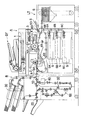
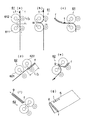
図1は画像形成装置本体A、自動原稿送り装置DF、単シート処理機(後処理装置)B、大容量給紙装置LTから成る画像形成システムの全体構成図である。
[Image forming system]
FIG. 1 is an overall configuration diagram of an image forming system including an image forming apparatus main body A, an automatic document feeder DF, a single sheet processing machine (post-processing apparatus) B, and a large capacity sheet feeding apparatus LT.
図示の画像形成装置本体Aは、画像読取部(画像入力装置)1、画像処理部2、画像書込部3、画像形成部4、給紙カセット5A,5B,5C、手差し給紙トレイ5D、第1給紙部6A,6B,6C,6D、第2給紙部6F、定着装置7、排紙部8、自動両面コピー給紙部(ADU)8Bを備えている。
The illustrated image forming apparatus main body A includes an image reading unit (image input device) 1, an
画像形成装置本体Aの上部には、自動原稿送り装置DFが搭載されている。画像形成装置本体Aの図示の左側面の排紙部8側には、単シート処理機(後処理装置)Bが連結されている。
An automatic document feeder DF is mounted on the upper part of the image forming apparatus main body A. A single sheet processing machine (post-processing apparatus) B is connected to the left side of the image forming apparatus main body A shown in the drawing on the
自動原稿送り装置DFの原稿台上に載置された原稿dは矢印方向に搬送され画像読取部1の光学系により原稿の片面又は両面の画像が読みとられ、イメージセンサCCDに読み込まれる。 The document d placed on the document table of the automatic document feeder DF is conveyed in the direction of the arrow, and an image on one or both sides of the document is read by the optical system of the image reading unit 1 and read by the image sensor CCD.
イメージセンサCCDにより光電変換されたアナログ信号は、画像処理部2において、アナログ処理、A/D変換、シェーディング補正、画像圧縮処理等を行った後、画像書込部3に信号を送る。
The analog signal photoelectrically converted by the image sensor CCD is subjected to analog processing, A / D conversion, shading correction, image compression processing, and the like in the
画像書込部3においては、半導体レーザからの出力光が画像形成部4の感光体ドラム4Aに照射され、潜像を形成する。画像形成部4においては、帯電、露光、現像、転写、分離、クリーニング等の処理が行われる。給紙カセット5A〜5C、手差し給紙トレイ5D、大容量給紙装置LTから第1給紙部6A〜6Eの各々により給送された用紙Sは転写手段4Bにより画像が用紙Sに転写される。画像を担持した用紙Sは、定着装置7により定着され、排紙部8から単シート処理機Bに送り込まれる。或いは搬送路切換板8Aにより自動両面コピー給紙部8Bに送り込まれた片面画像処理済みの用紙Sは再び画像形成部4において、両面画像処理後、排紙部8から排出される。
In the
[単シート処理機]
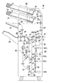
単シート処理機Bは、単シート処理搬入部10、単シート処理搬出部20、用紙付加部(表紙用紙給紙部)30、穿孔処理部(パンチ処理部、第1処理部)40、搬送部50、折り処理部(第2処理部)60から構成されている。
[Single sheet processing machine]
The single sheet processing machine B includes a single sheet processing carry-in
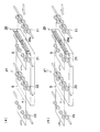
図2は、本発明に係る単シート処理機Bの全体構成図である。 FIG. 2 is an overall configuration diagram of the single sheet processing machine B according to the present invention.
〈単シート処理搬入部〉
単シート処理搬入部10には、画像形成装置本体Aから画像形成処理された用紙Sが導入される。
<Single sheet processing carry-in part>
Into the single sheet processing carry-in
単シート処理搬入部10の記録用紙導入位置は、画像形成装置本体Aの排紙部8の記録用紙排出位置に対向する。
The recording sheet introduction position of the single sheet processing carry-in
入口ローラ11に導入された記録用紙Sは、搬送路切換手段G1によって単シート処理搬出部20と穿孔処理部40の何れかに分岐される(分岐部)。
The recording sheet S introduced into the
〈単シート処理搬出部〉
パンチ処理及び折り処理が設定されない場合、搬送路切換手段G1は穿孔処理部40への搬送路を遮断し、単シート処理搬出部20への搬送路を開放する。
<Single sheet processing carry-out part>
When the punching process and the folding process are not set, the conveyance path switching unit G1 blocks the conveyance path to the
単シート処理搬出部20に向かう第1搬送路p1を通過する記録用紙Sは、搬送ローラ21,22に挟持されて直進し、排紙ローラ23により単シート処理搬出部20から排出され、昇降可能なメイン排紙トレイ24上に積載される。メイン排紙トレイ24上には最大2500枚の記録用紙S、カバー用紙Kを積載する事が出来る。
The recording sheet S passing through the first conveyance path p1 toward the single sheet processing carry-out
搬送路切換手段G2によって搬送ローラ22の用紙搬送方向下流側の図示上方に分岐された記録用紙Sは、第6搬送路p6の搬送ローラ25を通過し、排紙ローラ26によって排出され、単シート処理機B上部に配置された単シート処理排出部としてのサブ排紙トレイ(トップトレイ)27上に積載される。サブ排紙トレイ27上には、試しに画像形成した記録用紙やジャム処理後に排出される記録用紙等を収容する(単シート処理排出部)。
The recording sheet S branched upward in the drawing on the downstream side in the sheet conveyance direction of the
〈用紙付加部30〉
用紙付加部30の給紙皿31内に収容されたカバー用紙K、又はインサート用紙は、給紙手段32により分離、給送され、第5搬送路p5の搬送ローラ33,34,35,36に挟持されて、分岐部の上流側の搬送路に合流される(合流部)。
<
The cover sheet K or the insert sheet stored in the
用紙付加部30の給紙皿31は上下2段に配置され、各給紙皿31には最大500枚のカバー用紙K又はインサート用紙を収容する事が可能である。
The
なお、用紙付加部30にカバー用紙K、インサート用紙、又は記録用紙Sを装填して、画像記録を実行させず、オフラインで穿孔処理、折り処理を実施することも可能である。
Note that it is also possible to carry out the punching process and the folding process offline without loading the cover sheet K, the insert sheet, or the recording sheet S in the
以下、記録用紙S、カバー用紙K、インサート用紙を一括して用紙Sと総称する。 Hereinafter, the recording paper S, the cover paper K, and the insert paper are collectively referred to as paper S.
〈穿孔処理部40〉
単シート処理搬入部10の搬送路切換手段G1により分岐された用紙Sは、搬送路切換手段G1の下方に配置された搬送ローラ41に挟持され、穿孔処理部(第1処理部)40に搬送される(第2搬送路p2)。
<
The sheet S branched by the conveyance path switching unit G1 of the single sheet processing carry-in
穿孔処理部40の下流側の搬送路には、整合手段42が配置され、穿孔処理前の用紙Sの用紙幅方向を整合する。
An aligning means 42 is arranged in the transport path on the downstream side of the punching
穿孔処理部40の穿孔器は、図示しない駆動手段により駆動されるパンチと、パンチの刃部に嵌合するダイスとから成る。穿孔処理された用紙Sは、下方の搬送部50に送られる(パンチ機能)。
The punching device of the punching
図11は、各種後処理後の用紙S及び冊子SAの斜視図である。 FIG. 11 is a perspective view of the paper S and booklet SA after various post-processing.
穿孔処理部40により穿孔処理されて孔hが穿設された用紙Sを図11(a)の斜視図に示す。穿孔処理部40により穿孔処理された後、Z折り処理された用紙Sを図11(b)の斜視図に示す。
FIG. 11A is a perspective view of the paper S that has been punched by the punching
〈搬送部50〉
搬送部50に送られた用紙Sは、搬送ローラ51,52,53,54により挟持されて折り処理部60に搬送される。搬送ローラ51,52,53,54は、駆動源に接続する駆動ローラと、駆動ローラに圧接する従動ローラとから成る。各従動ローラはソレノイドSOLに接続して、駆動ローラに接離可能である。
<
The sheet S sent to the
穿孔処理された小サイズの用紙Sのうち、折り処理が行われない用紙Sは、搬送路切換手段G3により分岐された第3A搬送路p3Aを通過し、搬送ローラ600に挟持されて搬送される。穿孔処理された大サイズの用紙Sは、折り処理の要否に拘わらず搬送路切換手段G3の分岐位置の下方の第3B搬送路p3Bに搬送され、搬送ローラ53,54によって搬送され、折り処理部60に導入される。ここで第3A搬送路p3Aと、第3B搬送路p3Bとを合わせて第3搬送路を構成している。
Of the small-sized paper S that has been punched, the paper S that is not subjected to folding processing passes through the third A transport path p3A branched by the transport path switching means G3, and is nipped by the
なお、搬送部50に搬送路切換手段55が設けられ、2枚の小サイズの用紙Sを蓄積して搬送する事により、2枚同時に後述の折り処理を行う事ができる。また、搬送路切換手段55を設けず、用紙Sを1枚毎に折り処理するように構成し得ることは勿論である。
In addition, a conveyance
〈折り処理部60〉
搬送部50から折り処理部(第2処理部)60に搬送された用紙Sは、レジストローラ601に挟持されて搬送され、第1折り部61、第2折り部62、第3折り部63において、後述する外中折り、内中折り、Z折り、外三つ折り、内三つ折り、内四つ折り(以下、観音折りとも称す)、ダブルパラレル折り等の折り処理(折り機能)が実施されて、第4搬送路p4を介して第1搬送路p1に戻される。
<
The sheet S transported from the
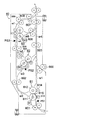
図3は、折り処理部60の断面図である。
FIG. 3 is a cross-sectional view of the
第1折り部61は、折りローラ611と折りローラ612とから成り圧接、離間可能な折りローラ対と、折りローラ611に圧接する折り搬送ローラ613、折りローラ612に圧接する折り搬送ローラ614、及び用紙Sの折り目部を前記折りローラ対の挟持位置に押し込むガイド部材615から構成されている。
The
第2折り部62及び第3折り部63は、第1折り部61とほぼ同一の構成をなす。
The
折り処理部60には、第1折り部61、第2折り部62及び第3折り部63を接続する複数の搬送路w1,w2,w3,w4,w5,w6,w7,w8及び用紙Sを挟持して搬送する複数の搬送ローラ602,6O3,604,605,606,607,608,609が配置されている。
The
[用紙折り処理]
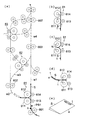
折り処理部60において、2面開きの外中折りと内中折り処理、3面開きのZ折り処理と外三つ折り処理と内三つ折り処理、4面開きの観音折り処理とダブルパラレル折り処理の7種が実行可能である。なお、折り処理機能が設定されている場合は、定着後の用紙Sが自動両面コピー給紙部8B側に途中まで送り込まれ、その後、反転されて画像形成装置本体Aから搬出される事により、画像面tを下側にして搬出される。
[Paper folding]
In the
〈外中折り処理〉
用紙Sへの用紙画像面外側の外中折り処理は、第1折り部61において行われる。
<Outside center folding>
The outer folding process on the outer side of the sheet image surface of the sheet S is performed in the
図4(a)は外中折り処理時の用紙Sの処理経路を示す正面図、図4(b)〜(d)は用紙Sの外中折り処理工程を示す模式図、図4(e)は折り処理された用紙Sの斜視図である。 4A is a front view showing the processing path of the sheet S during the outer and middle folding process, FIGS. 4B to 4D are schematic diagrams showing the outer and middle folding process steps of the sheet S, and FIG. FIG. 4 is a perspective view of a folded sheet S.
以下、用紙画像面外側の中折り処理工程を説明する。 Hereinafter, the middle folding process step on the outer side of the sheet image surface will be described.
(a) 画像形成装置本体Aにより画像面tを下側(フェイスダウン)にして形成されて排出される用紙Sは、単シート処理機Bの単シート処理搬入部10、搬送部50を通過して、画像面tを下側にしてレジストローラ601に挟持されて折り処理部60に導入される。
(A) The sheet S formed and discharged by the image forming apparatus main body A with the image surface t facing down (face down) passes through the single sheet processing carry-in
第1折り部61に搬送された用紙Sの先端部が、駆動回転する折りローラ611と折り搬送ローラ613の挟持位置を通過し、駆動回転する折りローラ612と折り搬送ローラ614に挟持されて搬送され、搬送路w1を直進する。センサPS1により用紙先端通過を検出されたのち、所定時間経過後、制御手段により、折りローラ611,612の駆動が停止され、用紙Sは所定位置に停止される。この用紙停止位置は、用紙Sの搬送方向中央部近傍が折りローラ611,612の中間位置である(図4(b)参照)。
The leading end of the sheet S conveyed to the
(b) 折りローラ612と折り搬送ローラ614の逆転駆動開始により、用紙Sの先端方向の二分の一箇所が折りローラ611,612の圧接位置に押し込まれて加圧され、中折りの折り目aが形成される(図4(c),(d)参照)。
(B) When reverse rotation driving of the
(c) 中折りの折り目aが形成された用紙Sは、駆動される折りローラ611,612に挟持されて排出され、折り目aを先頭にして搬送路w2,w3を通過し、第2折り部62に進行する。
(C) The sheet S on which the folded fold line a is formed is sandwiched and discharged by the driven
(d) 折り目aが形成されて中折り処理が完了した用紙Sは、駆動する搬送ローラ603,607に挟持されて搬送路w8,w4を通過して排出され、折り目aを先頭にして第4搬送路p4(図2参照)に進行する。
(D) The sheet S in which the fold a is formed and the middle folding process is completed is sandwiched by the driving
〈内中折り処理〉
用紙Sへの用紙画像面内側の内中折り処理は、第3折り部63において行われる。
<Inner folding process>
The inner folding process on the inner side of the sheet image surface of the sheet S is performed in the
図5(a)は内中折り処理時の用紙Sの処理経路を示す正面図、図5(b)〜(e)は用紙Sの内中折り処理工程を示す模式図、図5(f)は折り処理された用紙Sの斜視図である。 FIG. 5A is a front view showing the processing path of the sheet S during the inner / folding process, FIGS. 5B to 5E are schematic views showing the inner / folding process of the sheet S, and FIG. FIG. 4 is a perspective view of a folded sheet S.
折り処理部60に導入された用紙Sは、第1折り部61を無処理のまま通過し、搬送路w2,w6を経て、第3折り部63に送られる。第3折り部63において、折りローラ631,632によって画像面tを内側にして中折り処理された用紙Sは、折り目aを先頭にして、搬送路w8,w4を通過し第4搬送路p4(図2参照)に排出される。
The sheet S introduced into the
なお、画像形成装置本体A側において用紙Sの画像転写面を逆にして排出し、折り処理部60において外中折りと同じ搬送制御を実施してもよい。
Note that the image transfer surface of the image forming apparatus main body A may be ejected with the image transfer surface of the paper S reversed, and the
〈Z折り処理〉
用紙SへのZ折り処理は、第1折り部61においてZ折りの第1折り処理が行われ、第3折り部63においてZ折りの第2折り処理が行われる。
<Z-folding process>
In the Z-folding process on the paper S, the
図6(a)はZ折り処理時の用紙Sの処理経路を示す正面図、図6(b)〜(g)は、第1折り部61、第3折り部63によるZ折り処理工程を示す模式図である。
6A is a front view showing a processing path of the paper S during the Z-folding process, and FIGS. 6B to 6G show a Z-folding process step by the
レジストローラ601に挟持されて第1折り部61に搬送された用紙Sの先端部が、駆動回転する折りローラ611と折り搬送ローラ613の対向位置を通過し、駆動回転する折りローラ612と折り搬送ローラ614に挟持されて搬送される。センサPS1により用紙先端通過を検出されたのち、所定時間経過後、制御手段により、折りローラ611,612の駆動が停止され、用紙Sは所定位置に停止する。この用紙停止位置は、用紙Sの先端部が折りローラ611,612の対向位置より用紙搬送方向の全長Lの四分の一だけ前進した位置である(図6(b)参照)。
The leading edge of the sheet S sandwiched between the
折りローラ612の折りローラ611への圧接と、折りローラ612、折り搬送ローラ614の逆回転開始駆動とにより、用紙Sの先端方向の四分の一箇所が折りローラ611,612の圧接位置Nに押し込まれて加圧され、Z折りの第1の折り目bが形成される(図6(c)参照)。
By pressing the
Z折りの第1の折り目bが形成された用紙Sは、駆動回転する折りローラ611,612に挟持されて排出され、第1の折り目bを先頭にして第3折り部63に進行する(図6(d)参照)。
The sheet S on which the first fold line b of the Z fold is formed is sandwiched and discharged by the
第3折り部63に搬送された用紙Sの第1の折り目bが、駆動回転する折りローラ631,632間を通過し、センサPS3により用紙先端通過が検出されたのち、所定時間経過後、制御手段100により、折りローラ対の駆動が停止され、用紙Sは所定位置に停止する。この用紙停止位置は、用紙Sの後端部と折りローラ対の対向位置との間隔が、用紙Sの全長Lの二分の一である(図6(e)参照)。
After the first fold b of the sheet S conveyed to the
第1折り部61と同様にして折りローラ対の圧接と逆転駆動開始により、用紙Sの搬送方向中央部が折りローラ631,632の圧接位置に押し込まれて加圧され、Z折りの第2の折り目cが形成される(図6(f)参照)。この時、折りローラ631,632の圧接位置に用紙Sの先端部が先に到達し、次に第2の折り目cとなる湾曲部が圧接位置に到達する。
In the same manner as the
第2の折り目cが形成されてZ折り処理が完了した用紙Sは、駆動回転する折りローラ631,632及び搬送ローラ606に挟持されて排出され、第2の折り目cを先頭にして搬送路w8,w4を通過し、第1搬送路p1に排出される(図6(g)参照)。
The sheet S in which the second fold c is formed and the Z-folding process is completed is sandwiched and discharged by the driving and
図6(h)は、Z折り処理された用紙Sの斜視図である。bはZ折り処理された用紙Sの第1の折り目、cは第2の折り目、tは画像面を示す。Z折り処理された用紙Sは、ファイル装填に好適な形状となる。 FIG. 6H is a perspective view of the sheet S that has been Z-folded. b is a first fold of the sheet S that has been subjected to Z-folding, c is a second fold, and t is an image surface. The Z-folded paper S has a shape suitable for file loading.
〈外三つ折り処理〉
用紙Sへの外三つ折り処理は、第1折り部61において第1折り処理が行われ、第2折り部62において第2折り処理が行われる。
<Outer tri-fold processing>
In the outer tri-folding process on the paper S, the first folding process is performed in the
図7(a)は外三つ折り処理時の用紙Sの処理経路を示す正面図、図7(b)〜(g)は、第1折り部61、第2折り部62による外三つ折り処理工程を示す模式図である。
FIG. 7A is a front view showing the processing path of the paper S during the outer tri-fold process, and FIGS. 7B to 7G are outer tri-fold process steps by the
第1折り部61において、搬送された用紙Sの先端部通過をセンサPS2が検知して所定パルスを計数後に、制御手段100は用紙Sを所定位置に停止させる。
In the
用紙Sの先端部が折りローラ対の対向位置から用紙全長Lの三分の二の位置に停止した後、折りローラ611,612により第1折り処理が行われ、用紙Sに第1の折り目dが形成される(図7(b)〜(d)参照)。
After the leading edge of the sheet S stops at a position corresponding to two-thirds of the total sheet length L from the position where the pair of folding rollers is opposed, the first folding process is performed by the
第2折り部62において、用紙Sの第1の折り目dが折りローラ621,622の対向位置から用紙全長Lの三分の一の位置に停止した後、折りローラ621,622により第2折り処理が行われ、用紙Sに第2の折り目eが形成される(図7(e)〜(g)参照)。
In the
第2の折り目eが形成されて外三つ折り処理が完了した用紙Sは、駆動回転する第2折り部62の折りローラ621,622及び搬送ローラ604,605に挟持されて第2の折り目eを先頭にして搬送され、第3折り部63を通過し、搬送ローラ608,609に挟持されて排出され、第2の折り目cを先頭にして搬送路w4を通過し、第1搬送路p1に排出される(図7(a)参照)。
The sheet S on which the second fold e is formed and the outer tri-folding process is completed is sandwiched between the
図7(h)は、Z字型に外三つ折り処理された用紙Sの斜視図である。dは外三つ折り処理された用紙Sの第1の折り目、eは第2の折り目、tは画像面を示す。 FIG. 7H is a perspective view of the paper S that has been subjected to outer tri-fold processing into a Z-shape. d indicates the first fold of the sheet S that has been subjected to outer fold processing, e indicates the second fold, and t indicates the image surface.
〈内三つ折り処理〉
用紙Sへの内三つ折り処理は、第1折り部61において第1折り処理が行われ、第2折り部62において第2折り処理が行われる。
<Tri-fold processing inside>
In the inner fold process for the paper S, the first fold process is performed in the
内三つ折り処理は、外三つ折り処理時の用紙搬送経路は同じであるから、用紙Sの処理経路を示す正面図は省略する。 Since the inner tri-fold process has the same sheet conveyance path during the outer tri-fold process, a front view showing the process path of the sheet S is omitted.
図8(a)〜(f)は、第1折り部61、第2折り部62による内三つ折り処理工程を示す模式図である。
FIGS. 8A to 8F are schematic views showing an inner tri-fold process step by the
内三つ折り処理時には、第1折り部61、第2折り部62における用紙Sの停止位置が異なる。
At the time of the inner fold processing, the stop position of the paper S in the
第1折り部61において、用紙Sの先端部が折りローラ611,612の対向位置から用紙全長Lの三分の一の位置に停止した後、折りローラ611,612により第1折り処理が行われ、用紙Sに第1の折り目fが形成される(図8(a)〜(c)参照)。
In the
第2折り部62において、用紙Sの第1の折り目dが折りローラ621,622の対向位置から用紙全長Lの三分の一の位置に停止した後、折りローラ621,622により第2折り処理が行われ、用紙Sに第2の折り目gが形成される(図8(d)〜(f)参照)。
In the
図8(g)は、内三つ折り処理された用紙Sの斜視図である。fは内三つ折り処理された用紙Sの第1の折り目、gは第2の折り目、tは画像面を示す。 FIG. 8G is a perspective view of the sheet S that has been subjected to the inner folding process. f is the first fold of the sheet S that has been subjected to the inner folding process, g is the second fold, and t is the image plane.
〈ダブルパラレル折り処理〉
用紙Sへのダブルパラレル折り処理は、第1折り部61において第1折り処理が行われ、第2折り部62において第2折り処理が行われる。
<Double parallel folding>
In the double parallel folding process on the paper S, the first folding process is performed in the
ダブルパラレル折り処理は、外三つ折り処理時の用紙搬送経路は同じであるから、用紙Sの処理経路を示す正面図は省略する。 In the double parallel folding process, the paper conveyance path during the outer tri-folding process is the same, so the front view showing the processing path of the paper S is omitted.
図9(a)〜(f)は、第1折り部61、第2折り部62によるダブルパラレル折り処理工程を示す模式図である。
FIGS. 9A to 9F are schematic views showing a double parallel folding process performed by the
ダブルパラレル折り処理は、外三つ折り処理時や内三つ折り処理時の用紙搬送経路は同じであるが、用紙Sの停止位置が異なる。 In the double parallel folding process, the paper conveyance path during the outer trifold process and the inner trifold process is the same, but the stop position of the paper S is different.
第1折り部61において、用紙Sの先端部が折りローラ611,612の対向位置から用紙全長Lの二分の一の位置に停止した後、折りローラ611,612により第1折り処理が行われ、用紙Sに第1の折り目hが形成される(図9(a)〜(c)参照)。
In the
第2折り部62において、用紙Sの第1の折り目hが折りローラ621,622の対向位置から用紙全長Lの四分の一の位置に停止した後、折りローラ621,622により第2折り処理が行われ、用紙Sに内側の第2の折り目i、外側の第3の折り目jが同時に形成される(図9(d)〜(f)参照)。
In the
図9(g)は、ダブルパラレル折り処理された用紙Sの斜視図である。hはダブルパラレル折り処理された用紙Sの第1の折り目、iは第2の折り目、jは第3の折り目、tは画像面を示す。 FIG. 9G is a perspective view of the paper S that has been subjected to the double parallel folding process. h is a first fold of the sheet S that has been subjected to double-parallel folding processing, i is a second fold, j is a third fold, and t is an image plane.
〈観音折り処理〉
用紙Sへの観音折り処理は、第1折り部61において第1折り処理が行われ、第2折り部62において第2折り処理が行われ、第3折り部63において第3折り処理が行われる。
<Kannon folding process>
In the folding folding process on the paper S, the first folding process is performed in the
図10(a)は観音折り処理時の用紙Sの処理経路を示す正面図、図10(b)〜(g)は、第1折り部61、第2折り部62、第3折り部63による観音折り処理工程を示す模式図である。
FIG. 10A is a front view showing the processing path of the paper S during the kannon folding process, and FIGS. 10B to 10G are the
第1折り部61において、用紙Sの先端部が折りローラ611,612の対向位置から用紙全長Lの四分の一の位置に停止した後、折りローラ611,612により第1折り処理が行われ、用紙Sに第1の折り目kが形成される(図10(b)〜(d)参照)。
In the
第1の折り目kが形成された用紙Sは、第2折り部62において、用紙Sの後端部と折りローラ621,622の対向位置との間隔が用紙全長Lの四分の一の位置に停止した後、折りローラ621,622により第2折り処理が行われ、用紙Sに第2の折り目mが形成される(図10(e),(f)参照)。
The sheet S on which the first fold line k is formed is such that the interval between the rear end portion of the sheet S and the opposing position of the
第1の折り目kと第2の折り目mが形成された用紙Sは、第3折り部63において、用紙Sの搬送方向中央部が折りローラ631,632の対向位置に停止した後、折りローラ631,632により第3折り処理が行われ、用紙Sに第3の折り目nが形成される(図10(g),(h)参照)。
The sheet S on which the first fold line k and the second crease line m are formed is the
観音折り処理が完了した用紙Sは、第3折り部63から搬送ローラ606,607に挟持されて排出され、第3の折り目nを先頭にして第1搬送路p1に排出される(図10(a)参照)。
The sheet S for which the folding-in folding process has been completed is sandwiched and ejected from the
図10(i)は、観音開き型に観音折り処理された用紙Sの斜視図である。kは用紙Sの第1の折り目、mは第2の折り目、nは第3の折り目、tは画像面を示す。 FIG. 10 (i) is a perspective view of the paper S that has been subjected to the double folding process. k is the first fold of the paper S, m is the second fold, n is the third fold, and t is the image plane.
〈ミシン目機能〉
図12(a)は、ミシン目入れ手段28を有する第1搬送路p1(図2参照)の斜視図である。
<Perforation function>
FIG. 12A is a perspective view of the first transport path p1 (see FIG. 2) having the perforation means 28. FIG.
第1搬送路p1上で、入口ローラ11の用紙搬送方向下流側で搬送ローラ21の上流側には、ミシン目入れ手段28が配置されている(図2参照)。用紙Sは、ミシン目入れ手段28の刃付き拍車28a等によって所定の位置にミシン目uが形成される。
On the first conveyance path p1, a perforation means 28 is disposed on the downstream side in the sheet conveyance direction of the
〈単シート断裁機能〉
図12(b)は、カッター手段29を有する第1搬送路p1の斜視図である。
<Single sheet cutting function>
FIG. 12B is a perspective view of the first transport path p <b> 1 having the cutter means 29.
ミシン目入れ手段28に並列配置、又は交換可能に設置されるカッター手段29のロールカッター29aは、用紙Sを所定の位置のスリットvにより切断する(単シート断裁機能)。
The
「平綴じ機」
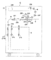
図13は、平綴じ機(後処理装置)Dの正面図である。
"Side stitcher"
FIG. 13 is a front view of a flat stitching machine (post-processing apparatus) D.
〈平綴じ機能〉
画像形成装置本体A又は他の後処理装置から排出され、平綴じ機Dの入口部(平綴じ搬入部)101に導入された用紙Sは、搬送路切換手段G4の上方の搬送路q1又は下方の搬送路q2の何れかに搬送される。搬送路q1に分岐された用紙Sは、搬送ローラ102〜105により挟持されて搬送され、排紙ローラ106によって排出され、平綴じ機D上部に配置された平綴じ排出部としてのサブ排紙トレイ(トップトレイ)107上に積載される。サブ排紙トレイ107上には、試しに画像形成した記録用紙やジャム処理後に排出される記録用紙等を収容する。
<Side binding function>
The sheet S discharged from the image forming apparatus main body A or other post-processing apparatus and introduced into the entrance part (flat stitching carry-in part) 101 of the flat stitching machine D is transport path q1 above or below the transport path switching means G4. Is conveyed to one of the conveyance paths q2. The paper S branched into the conveyance path q1 is nipped and conveyed by the
搬送路q2に分岐された用紙Sは、搬送ローラ110,111により挟持されて搬送され、レジストローラ112によって放出され、傾斜配置された中間スタッカ113上に逐次載置される。中間スタッカ113上に積載された用紙Sは、用紙後端突当部材114による用紙後端整合と、用紙幅整合部材115による用紙幅整合とにより位置決めされた後、ステイプラ(綴じ器)116によって、用紙Sの側縁部近傍の1箇所又は2箇所に綴じ針SPが打針され、冊子SAが作製される(ステイプル機能)。図11(c)はステイプル処理された冊子SAの斜視図である。
The sheet S branched to the conveyance path q2 is nipped and conveyed by the
ステイプル処理された冊子SAの後端部は、回動する排出ベルト117に固定された排出爪118により中間スタッカ113上を斜め上方に搬送され、平綴じ排出部の排出ローラ119によって排出され、メイン排紙トレイ(開放型排出部)120上に載置される。
The rear end portion of the stapled booklet SA is conveyed obliquely upward on the
〈テープバインダ機能〉
テープバインダ機能が設定されると、用紙後端突当部材114が中間スタッカ113面から待避する。中間スタッカ113上に積載され、用紙後端突当部材114による用紙後端整合と、用紙幅整合部材115による用紙幅整合とにより位置決めされた用紙束は、用紙束グリップ搬送部材121により把持されて中間スタッカ122上を斜め下方に配置された背面部突当部材123に向かって進行する。
<Tape binder function>
When the tape binder function is set, the sheet trailing
背面部突当部材123の突当面には、予め接着テープ124が当接して待機している。中間スタッカ122上を下降する用紙束の後端部は、背面部突当部材123に支持された接着テープ124に当接して停止する。
The
背面部突当部材123はテープ加熱手段125によって加熱されていて、接着テープ124の接着面は溶融されている。用紙束の背部は、接着テープ124の溶融状態の接着面に圧接して接着される。
The back
接着テープ124の幅寸法は、用紙束の背部厚さより長く形成されている。用紙束の背部を接着した後、上下一対の押圧部材126が用紙束厚さ方向に移動して、接着テープ124の両端部を折り曲げて、用紙束の上下面に接着テープ124の溶融状態の接着面を圧接して接着して冊子SAを完成させる。図11(e)は、テープバインダ機能により作製された冊子SAの斜視図である。
The width dimension of the
テープバインダ処理の終了後、用紙束グリップ搬送部材121の把持及び押圧部材126の押圧が解除され、冊子SAの後端部は、回動する排出ベルト127に固定された排出爪128により中間スタッカ122上を斜め上方に搬送され、中間スタッカ113を経て、排出ローラ119によって排出され、メイン排紙トレイ120上に載置される。
After completion of the tape binder processing, the gripping of the sheet bundle
〈糊付け機能〉
平綴じ機Dは、前記テープバインダ機能の代わりに糊付け製本機能を配置する事も可能である。糊付け製本機能は、背面部突当部材123の近傍に回転する糊塗布ローラ、糊塗布ローラ移動手段、糊収納容器を配置したものである。
<Gluing function>
The flat stitching machine D can also be provided with a glue binding function instead of the tape binder function. In the gluing bookbinding function, a glue applying roller, a glue applying roller moving means, and a glue container are arranged in the vicinity of the back
糊付け機能が設定されると、回転する糊塗布ローラに保持された溶融状態の糊が、用紙束グリップ搬送部材121により把持された用紙束の背面部に塗布されて接合され、冊子SAが作製される。
When the gluing function is set, the melted glue held by the rotating glue application roller is applied and joined to the back side of the sheet bundle gripped by the sheet bundle
[中綴じ機]
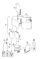
図14は中綴じ機(後処理装置)Cの正面図、図15は左側面図、図16は右側面図、図17は平面図である。図18は、中綴じ機Cの用紙搬送工程を示す模式図、図19は中綴じ機Cの中折り、中綴じ処理工程の用紙搬送を示す斜視図である。
[Saddle Stitcher]
14 is a front view of the saddle stitcher (post-processing apparatus) C, FIG. 15 is a left side view, FIG. 16 is a right side view, and FIG. 17 is a plan view. FIG. 18 is a schematic diagram illustrating a sheet conveyance process of the saddle stitching machine C, and FIG. 19 is a perspective view illustrating sheet conveyance of the saddle stitching machine C in the middle folding and saddle stitching process.
画像形成装置本体A又は他の後処理装置から排出され、中綴じ機Cの入口部(中綴じ搬入部)201に導入された用紙Sは、入口ローラ202により挟持され、搬送路切換手段G5の上方の搬送路r1又は下方の搬送路r2の何れかに搬送される。
The sheet S discharged from the image forming apparatus main body A or other post-processing apparatus and introduced into the entrance portion (saddle stitching carry-in portion) 201 of the saddle stitching machine C is sandwiched by the
搬送路r1に分岐された用紙Sは、搬送ローラ203〜207により挟持されて搬送され、搬送路切換手段G6の上方の搬送路r3又は下方の搬送路r4の何れかに搬送される。
The sheet S branched to the conveyance path r1 is nipped and conveyed by the
上方の搬送路r3に進行した用紙Sは、排紙ローラ208によって排出され、中綴じ機C上部に配置された中綴じ排出部としてのサブ排紙トレイ(トップトレイ)209上に積載される。
The paper S that has traveled to the upper conveyance path r3 is discharged by the
下方の搬送路r4に進行した用紙Sは、搬送ローラ210〜213により挟持されて搬送され、中綴じ排出部の排紙ローラ214によって排出される。
The sheet S that has advanced to the lower conveyance path r4 is nipped and conveyed by the
〈第1直角偏向搬送〉
搬送路切換手段G5の下方の搬送路r2に搬送された用紙Sは、ほぼ垂直に下降し、所定位置に一時停止して収納される。この停止位置において、後続の少数枚の用紙Sが重ね合わせられて収容される(図14の実線、図15の破線)。
<First right angle deflection transport>
The sheet S transported to the transport path r2 below the transport path switching means G5 descends substantially vertically, and is temporarily stopped and stored at a predetermined position. At this stop position, the subsequent small number of sheets S are stacked and accommodated (solid line in FIG. 14, broken line in FIG. 15).
〈第2直角偏向搬送〉
収容された用紙Sは搬送ローラ215〜218と図示しない案内板によって図14の紙面に対して直角手前方向に偏向移動されて、中綴じ機C内部の前面側Cfに回り込む搬送路r5を用紙面を直立させた状態で通過し、所定位置に一時停止する(図14の破線、図15の実線で示す位置)。
<Second right angle deflection conveyance>
The accommodated paper S is deflected and moved in a direction perpendicular to the paper surface of FIG. 14 by the
〈第3直角偏向搬送〉
次に、用紙Sは搬送ローラ219によって垂直上方に搬送された後、水平方向に偏向され、搬送ベルト220、搬送ローラ221によって中綴じ機C内部の背面側に移動される(搬送路r6)。
<Third right-angle deflection conveyance>
Next, the sheet S is conveyed vertically upward by the conveying
〈中折り機能〉
搬送ベルト220の用紙搬送方向下流側には、折り処理部230が配置されている。折り処理部230は折りローラ231,232,233、折り板234,235から構成されている。
<Folding function>
A
折り処理部230に到達した少数枚の用紙Sは、互いに逆方向に回転する折りローラ231,232及び直進する折りナイフ234によって挟持され、用紙搬送方向中央で用紙幅方向にわたって折り目を形成する(図4(e)、図5(f)参照)。
A small number of sheets S that have reached the
その後、折りローラ231,232を逆回転させる。折り目が形成された用紙Sは、折りローラ231,232から離間されて元の水平搬送路に戻される。用紙Sは、引き続き、搬送ベルト236(図14参照)によって、折り目の延長線方向(図15、図16の紙面直角方向、図14の矢示方向)の搬送路r7に搬送され、中綴じ処理部240に送り込まれる。
Thereafter, the
このように、折り処理部230は、少数枚の用紙Sを中折り処理して、折り目をしっかり付け、逐次、中綴じ処理部240に送り込む事により、折り目部の膨らみが少ない高品位の冊子を作製する事ができる。
In this way, the
〈三つ折り機能〉
折り処理部230において、用紙Sの先端部が折りローラ231,232の対向位置から用紙全長Lの三分の一の位置に停止した後、折りローラ231,232により第1折り処理が行われ、用紙Sに第1の折り目fが形成される。
<Tri-fold function>
In the
用紙Sの第1の折り目fが折りローラ231,232の対向位置から用紙全長Lの三分の一の位置に停止した後、折りローラ232,233により第2折り処理が行われ、用紙Sに第2の折り目gが形成される(図8(g)参照)。
After the first crease f of the sheet S stops at a position that is one third of the total length L of the sheet from the position where the
折り処理部230において、三つ折り処理された用紙Sは、複数の搬送ローラ237と案内板から成る搬送路r8を通過し、排紙ローラ238によって排紙トレイ(トップトレイ)239に排出される。
In the
〈中綴じ機能〉
折り処理部230において中折り処理された用紙Sは、搬送ベルト及び図示しない案内手段によって搬送路r7方向に進行し、中綴じ処理部240の鞍掛部材241上に載置される。後続の中折り処理された用紙Sも引き続き搬送路r7を通過して鞍掛部材241上に積載される。
<Saddle stitching function>
The sheet S that has been subjected to the middle folding process in the
鞍掛部材241は上方にほぼ直角な凸形状をなし、その頂部稜線上に中折り処理された用紙Sの折り目a(図4(e)、図5(f)参照)が載置される。
The
鞍掛部材241上に載置された複数枚の用紙Sは、幅整合部材242によって位置揃えされる。
The plurality of sheets S placed on the
鞍掛部材241の上方には、打針機構243が上下方向に移動可能に支持されている。鞍掛部材241の内部には、受針機構244が固定されている。
Above the
打針機構242と受針機構243とから成る二分割構造の綴じ手段は、用紙折り目方向に2組配置されている。操作部において、中綴じ処理が設定されると、打針機構243が下降して中綴じ処理を行う。即ち、2組の綴じ手段は鞍掛部材241上の用紙束の折り目aに沿って、中央振り分け2箇所に綴じ針SPを打針する。図11(d)は、中折り処理、中綴じ処理された冊子SAの斜視図である。
Two sets of binding means having a two-part structure comprising the needle-striking
〈用紙束断裁機能〉
中綴じ処理部240において中綴じ処理された用紙束は、揺動可能な案内部材251に支持されて鎖線方向に揺動されて搬送ベルト252上に載置される。搬送ベルト252の回動により用紙束は斜め下方に搬送され、更に、回動する搬送ベルト253により移送されて所定位置に停止される。
<Paper bundle cutting function>
The sheet bundle that has undergone saddle stitching processing in the saddle
その後、搬送ベルト253は揺動して水平状態になる。この水平状態になった搬送ベルト253上に載置された用紙束の小口(折り目の反対側の自由端部)は、冊子SAの用紙枚数によって不揃いになっているから、断裁手段(トリマー)250により断裁して、小口を揃える。
Thereafter, the
断裁処理されて作製された冊子SAは、逆回転する搬送ベルト253に載置され、搬送ベルト253に固定された排紙爪254により冊子SAの後端部が押圧された状態で搬送され、搬送ベルト253の先端部から矢示方向に落下する。落下した冊子SAは、回動する搬送ベルト255により中綴じ機Cの前面側Cfの外方に配置された排紙トレイ256に排出される。
The booklet SA produced by the cutting process is placed on the
また、別の機構として、搬送ベルト253の位置に中綴じ機本体から引き出し可能なスタッカを設け、ここに冊子SAをスタックするようにしてもよい。
As another mechanism, a stacker that can be pulled out from the saddle stitcher main body may be provided at the position of the
[大容量載置機]
図20は、用紙Sを導入する工程を示す大容量載置機(後処理装置)Eの正面図である。
[Large capacity placement machine]
FIG. 20 is a front view of a large-capacity placement machine (post-processing apparatus) E showing the process of introducing the paper S.
画像形成装置本体A又は他の後処理装置から排出され、大容量載置機Eの入口部(大容量載置搬入部)301に導入された用紙Sは、入口ローラ302により挟持され、搬送路切換手段G7の上方の搬送路s1又は下方の搬送路s2の何れかに搬送される。
The sheet S discharged from the image forming apparatus main body A or another post-processing apparatus and introduced into the entrance portion (large-capacity placement carry-in portion) 301 of the large-capacity placement machine E is nipped by the
搬送路s1に分岐された用紙Sは、搬送ローラ303により挟持されて搬送され、搬送路切換手段G8の上方の搬送路s3又は下方の搬送路s4の何れかに搬送される。
The sheet S branched to the transport path s1 is nipped and transported by the
上方の搬送路s3に進行した用紙Sは、搬送ローラ304を経て排紙ローラ305によって排出され、大容量載置機Eの上部に配置された大容量載置排出部としてのサブ排紙トレイ(トップトレイ)306上に積載される。
The paper S that has traveled to the upper transport path s3 is discharged by the
下方の搬送路s4に進行した用紙Sは、搬送ローラ307〜312により挟持されて搬送され、大容量載置排出部の排紙ローラ313によって機外に排出され、他の後処理装置に送り込まれる。
The sheet S that has traveled to the lower transport path s4 is nipped and transported by the
搬送路s2に進入した用紙Sは、搬送ローラ314に挟持されて搬送され、更に、用紙Sの先端部が回動するベルト315に固定されたグリッパ316に把持されて図示の左方向に進行する。
The sheet S that has entered the conveyance path s2 is nipped and conveyed by the
ベルト315の左端近傍には用紙先端規制部材317が待機している。用紙先端規制部材317は導入される用紙Sのサイズに対応した所定位置に移動して停止するとともに、用紙先端整合を行う。
In the vicinity of the left end of the belt 315, a paper front
用紙Sの先端部が用紙先端規制部材317に当接すると、グリッパ316の把持が解除されて、用紙Sは落下して用紙載置台318上に載置される。
When the leading edge of the paper S comes into contact with the paper leading
用紙載置台318は昇降部材320に支持されて昇降可能である。昇降部材320は図示しない駆動手段によって駆動され、案内部材321に沿って昇降する。
The sheet placing table 318 is supported by the elevating
用紙載置台318上に用紙Sが逐次積載されるに従って、用紙載置台318、昇降部材320は下降し、積載された用紙Sの最上面は初期位置を維持する。
As the sheets S are sequentially stacked on the sheet mounting table 318, the sheet mounting table 318 and the elevating
図21は、用紙Sを排出する工程を示す大容量載置機Eの正面図である。 FIG. 21 is a front view of the large-capacity placement machine E showing the process of discharging the paper S.
大容量載置機Eに収容された用紙Sを取り出す場合には、操作部において大容量載置機Eの開放を指定する。この支持により、駆動手段は昇降部材320を下降させる。昇降部材320の下降により用紙載置台318も一体となって下降する。
When taking out the paper S stored in the large-capacity placement machine E, the operation unit designates opening of the large-capacity placement machine E. With this support, the driving means lowers the elevating
大容量載置機Eの下部には、車輪323を有する台車(着脱式大容量載置部)322が移動可能に配置されている。用紙載置台318が台車322の上面に当接して搭載され、昇降部材320はこれより更に下降を続け、用紙載置台318の保持を解除して停止する。
Below the large capacity mounting machine E, a carriage (detachable large capacity mounting part) 322 having
操作者は、大容量載置機Eの前面扉を開き、手動又は電動により、台車322を手前側に引き出せば、台車322に搭載された用紙載置台318上に積載された用紙Sは、容易に外部に取り出す事が出来る。
If the operator opens the front door of the large capacity loading machine E and manually or electrically pulls out the
[くるみ製本機]
図22はくるみ製本ユニットF1と断裁ユニットF2とから成るくるみ製本機F(後処理装置)の斜視図、図23はくるみ製本ユニットF1の正面図である。
[Washing bookbinding machine]
FIG. 22 is a perspective view of a case binding machine F (post-processing apparatus) including a case binding unit F1 and a cutting unit F2, and FIG. 23 is a front view of the case binding unit F1.
くるみ製本搬入部401に導入された用紙Sは、搬送路切換手段G9により、上部の排紙路と水平搬送路との何れかに選択され、搬送される。
The paper S introduced into the case binding carry-in
〈無処理の用紙搬送〉
上部の排紙路に進入した用紙Sは、搬送ローラ402,403に挟持されて排紙ローラ404によりくるみ製本排出部としてのサブ排紙トレイ(トップトレイ)405に排出される。
<Unprocessed paper transport>
The paper S that has entered the upper paper discharge path is sandwiched between the
操作部において、ストレート排紙が設定されると、搬送路切換手段G9は上部の排紙路を閉鎖し、水平搬送路を開放し用紙Sの水平搬送を可能にする。水平搬送路に進入した用紙Sは、搬送ローラ406〜409に挟持されて搬送され、糊塗布を行わない用紙Sは、排紙ローラ410に挟持されて、くるみ製本排出部411から機外に排出される(搬送路X1)。
When straight discharge is set in the operation unit, the conveyance path switching unit G9 closes the upper discharge path, opens the horizontal conveyance path, and enables the sheet S to be conveyed horizontally. The sheet S that has entered the horizontal conveyance path is nipped and conveyed by the
〈カバー用紙Kの給紙〉
くるみ製本ユニットF1の下部に配置された給紙カセット441に収容されたカバー用紙Kは、送り出しローラ442、分離ローラ443により給送され、搬送ローラ444,445により搬送され、搬送路切換手段G9の下方の搬送路を通過して搬送路X1方向に搬送される。なお、給紙カセットは441は上下2段に設けられている。
<Feeding cover paper K>
The cover paper K stored in the
〈糊塗布処理の用紙搬送〉
くるみ製本モードが設定されると、給紙カセット441から送り出されたカバー用紙K、及び画像形成装置本体A又は他の後処理装置から排出される用紙Sは、駆動回転される搬送ローラ406〜409により挟持されて搬送され、用紙Sの先端部が位置決め部材412に当接すると、用紙Sの曲がりが修正され、搬送方向に位置決めが行われる(搬送路X1)。その後、駆動が停止され、図示されていない駆動手段により搬送ローラ406〜409の各上ローラが用紙面から上方に待避して、搬送ローラ406〜409の圧接が解除される。
<Paper transport for glue application>
When the case binding mode is set, the cover paper K sent out from the
更に、用紙Sは駆動回転される搬送ローラ413に挟持されて、90度偏向された搬送方向に搬送される(搬送路Y1)。用紙Sは引き続き搬送ローラ414により挟持されてUターン搬送され積載手段420に送り込まれる(搬送路Z)。
Further, the sheet S is nipped by a
〈用紙Sへの糊塗布処理〉
糊吐出装置430は、搬送ローラ413により搬送路Y1から搬送路Zに走行する用紙Sの一方の側縁部に線状又は断続する破線状に糊を吐出して、用紙Sの上面に糊塗布部を形成する。
<Glue application processing to paper S>
The
〈用紙Sの積載、整合、加圧処理〉
1枚目の糊塗布処理されない用紙Sは、駆動回転される搬送ローラ414によって挟持搬送されて搬送路Y2に搬送され、積載台421上に載置される。後続の2枚目以降の糊塗布処理された用紙Sは、搬送ローラ414により挟持搬送されて搬送路Y2に搬送され、積載台421上の先行の用紙S上に積載される。
<Stacking, alignment, and pressurization of paper S>
The first sheet S that is not subjected to the glue application process is nipped and conveyed by the
加圧手段422は、積載台421上に載置された先行の用紙束の糊塗布部形成面の背面側を加圧して移動し、用紙間の接着を確実にする。用紙Sの両側端部は、側端ストッパ423,424により位置決めされる。なお、用紙Sの先端部、後端部、両側端部の整合、位置決めは、加圧手段422による加圧処理の前に行う。加圧手段422による用紙Sの加圧処理は、2枚目以降の用紙Sが積載台421上に載置される都度行っても良い。又は、用紙Sが複数枚積載される毎に加圧処理を行ってもよい。
The pressurizing
以上の工程により糊付け処理された1冊の冊子SAが完成する。このくるみ製本ユニットF1では、例えば、最大200枚の用紙Sを糊付け処理して製本化する事ができる。 One booklet SA subjected to the gluing process by the above steps is completed. In the case binding unit F1, for example, a maximum of 200 sheets S can be glued to be bound.
積載台421の用紙積載面の一部には、駆動ローラ431と従動ローラ432に巻回された複数本の排出ベルト433が回動可能に配置されている。
A plurality of
最終枚目の用紙Sが積載台421上に積載され、加圧処理されて、糊付けくるみ製本された冊子SAは、回動する排出ベルト433の排出爪434により冊子SAの後端部を保持されて、積載台421の載置面上を滑走して、排出口436に設けた排出ローラ435に挟持されて、断裁ユニットF2に排出される(搬送路X2)。この排紙処理に先立って、加圧手段422及び側端ストッパ423を図示しない駆動手段により搬送路の上方に待避させておく。
The booklet SA, the final sheet S of which is stacked on the stacking table 421, pressed, and glued and bound, is held at the trailing edge of the booklet SA by the
また、糊付けの代わりに、ステイプルによってくるみ製本を行う事も可能である。この場合、用紙Sをカバー用紙Kでくるんだ後、平綴じ機Dで説明したようなステイプル処理を施せばよい。 Further, instead of gluing, it is also possible to perform case binding using staples. In this case, after the paper S is wrapped with the cover paper K, the stapling process as described in the flat stitching machine D may be performed.
〈くるみ製本断裁機能〉
くるみ製本ユニットF1の排出口436から排出されたくるみ製本処理済みの冊子SAは、断裁ユニットF2に導入され、回動する搬送ベルト451により搬送されて、冊子SAの先端部がストッパ452に当接して所定位置に停止する。
<Cut bookbinding cutting function>
The booklet SA that has been subjected to the case binding process that has been discharged from the
この停止位置に置いて、断裁刃453,454,455が下降して、冊子SAの糊塗布部以外の三方の端縁を断裁して冊子SAを仕上げ加工する。
At this stop position, the
仕上げられた冊子SAはくるみ製本ユニットF1の前面側に搬送され(搬送路Y3)、機外に排出され、昇降排紙台(くるみ製本載置部)456上に載置される。なお、昇降排紙台456は図示しない台車を有し、くるみ製本本体に対して着脱可能に構成してもよい。
The finished booklet SA is transported to the front side of the case binding unit F1 (conveyance path Y3), is discharged out of the apparatus, and is placed on the lifting / discharging tray (case binding placement unit) 456. The elevating / discharging
[画像形成システム]
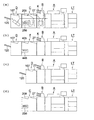
図24は、画像形成装置本体A、単シート処理機B、及び他の後処理装置(C,D,F)から成る各種画像形成システムの実施の形態を示す模式図である。
[Image forming system]
FIG. 24 is a schematic diagram showing an embodiment of various image forming systems including an image forming apparatus main body A, a single sheet processing machine B, and other post-processing apparatuses (C, D, F).
図24(a)は、画像形成装置本体Aの排紙部8側に、単シート処理機B、中綴じ機C、平綴じ機Dを連結した画像形成システムである。
FIG. 24A shows an image forming system in which a single sheet processing machine B, a saddle stitching machine C, and a flat stitching machine D are connected to the
単シート処理機B内で穿孔、折り、ミシン目入れ、スリット断裁等の後処理機能を施さず、無処理で排出される用紙Sは、画像形成システム上部に配置されたサブ排紙トレイ27に収容される。又は、次工程の中綴じ機Cに送られる。
In the single sheet processing machine B, the post-processing functions such as punching, folding, perforation, slit cutting, etc. are not performed, and the paper S discharged without processing is placed in the sub
単シート処理機Bにより穿孔、折り等の後処理機能が行われた用紙S、無処理の用紙Sは、中綴じ機Cに導入される。ここで中綴じ処理を要しない用紙Sは、サブ排紙トレイ(トップトレイ)209に排出される。中綴じ機Cにおいて中折り処理、中綴じ処理されて作製された冊子SAは、中綴じ機Cの前面側Cfに配置された排紙トレイ256に収容される。
The sheet S that has been subjected to post-processing functions such as punching and folding by the single sheet processing machine B and the unprocessed sheet S are introduced into the saddle stitching machine C. Here, the paper S that does not require the saddle stitching process is discharged to a sub discharge tray (top tray) 209. The booklet SA produced by the saddle stitching machine C by the middle folding process and the saddle stitching process is accommodated in a
単シート処理機Bから搬入された用紙Sに平綴じ、テープバインド等の後処理機能を行う場合には、用紙Sは中綴じ機C内を無処理で通過し、平綴じ機Dに導入される。ここで平綴じ、テープバインド等の後処理を要しない用紙Sは、サブ排紙トレイ(トップトレイ)107に排出される。 In the case of performing post-processing functions such as flat binding and tape binding on the paper S carried in from the single sheet processing machine B, the paper S passes through the saddle stitching machine C without any processing and is introduced into the flat binding machine D. The Here, the paper S that does not require post-processing such as flat binding and tape binding is discharged to the sub discharge tray (top tray) 107.
平綴じ機Dにおいて平綴じ、テープバインド等の後処理を施された冊子SAは、メイン排紙トレイ120に収容される。
The booklet SA that has undergone post-processing such as flat binding and tape binding in the flat binding machine D is accommodated in the main
図24(b)は、中綴じ機Cに代えて、くるみ製本機Fを配置した画像形成システムの模式図である。 FIG. 24B is a schematic diagram of an image forming system in which a case binding machine F is arranged instead of the saddle stitching machine C.
単シート処理機Bから搬入された用紙Sに、くるみ製本処理が行われて作製された冊子SAは、くるみ製本機Fの前面側に配置された昇降排紙台456に排出される。 The booklet SA produced by carrying out the case binding process on the paper S carried in from the single sheet processing machine B is discharged to a lifting / lowering delivery table 456 arranged on the front side of the case binding machine F.
くるみ製本処理を行わない用紙Sは、サブ排紙トレイ209に排出される。又は、次工程の平綴じ機Dに送られる。平綴じ機Dにおいて平綴じ、テープバインド等の後処理を施された冊子SAは、メイン排紙トレイ120に収容される。
The paper S that is not subjected to case binding processing is discharged to the sub
図24(c)は、画像形成装置本体A、単シート処理機B、平綴じ機Dから成る画像形成システムの模式図である。 FIG. 24C is a schematic diagram of an image forming system including the image forming apparatus main body A, the single sheet processing machine B, and the flat stitching machine D.
単シート処理機Bにおいて、穿孔、Z折り、ミシン目入れ等の後処理を施された用紙Sは、平綴じ機Dにおいて、平綴じ、テープバインド処理が行われる。 The sheet S that has been subjected to post-processing such as punching, Z-folding, perforation in the single sheet processing machine B is subjected to flat binding and tape binding processing in the flat binding machine D.
図24(d)は、画像形成装置本体A、単シート処理機B、中綴じ機Cから成る画像形成システムの模式図である。 FIG. 24D is a schematic diagram of an image forming system including the image forming apparatus main body A, the single sheet processing machine B, and the saddle stitching machine C.
単シート処理機Bにおいて送り出されたカバー用紙Kは、中綴じ機Cにおいて画像形成装置本体Aから送り出された用紙Sに重ね合わされ、中折り、中綴じの後処理が行われる。 The cover sheet K sent out in the single sheet processing machine B is superimposed on the sheet S sent out from the image forming apparatus main body A in the saddle stitching machine C, and post-processing of half-folding and saddle stitching is performed.
図25は、画像形成装置本体A、平綴じ機D、大容量載置機Eから成る各種画像形成システムの実施の形態を示す模式図である。 FIG. 25 is a schematic diagram showing embodiments of various image forming systems including the image forming apparatus main body A, the flat stitching machine D, and the large-capacity placement machine E.
図25(a)は、画像形成装置本体A、平綴じ機Dから成る画像形成システムの模式図である。このシステムは、図24(c)のシステムから単シート処理機Bを除いたものである。画像形成装置本体Aから排出された用紙Sは、平綴じ機Dにより平綴じ、テープバインド処理が行われる。 FIG. 25A is a schematic diagram of an image forming system including the image forming apparatus main body A and the flat stitching machine D. This system is obtained by removing the single sheet processing machine B from the system of FIG. The paper S discharged from the image forming apparatus main body A is subjected to flat binding and tape binding processing by the flat binding machine D.
図25(b)は、画像形成装置本体A、2組の大容量載置機E、平綴じ機Dから成る画像形成システムの模式図である。このシステムは、図24(a)のシステムに2組の大容量載置機Eを介装させたものである。画像形成装置本体Aから排出される大量の用紙Sは、2組の大容量載置機Eに収容する事が出来る。また、平綴じ機Dにより平綴じ、テープバインド処理も可能である。 FIG. 25B is a schematic diagram of an image forming system including the image forming apparatus main body A, two sets of large-capacity placement machines E, and flat stitching machines D. In this system, two sets of large-capacity mounting machines E are installed in the system shown in FIG. A large amount of paper S discharged from the image forming apparatus main body A can be accommodated in two sets of large capacity loading machines E. Further, flat binding and tape binding can be performed by the flat binding machine D.
図25(c)は、画像形成装置本体A、1組の大容量載置機E、平綴じ機Dから成る画像形成システムの模式図である。このシステムは、図25(a)のシステムに1組の大容量載置機Eを介装させたものである。 FIG. 25C is a schematic diagram of an image forming system including the image forming apparatus main body A, a set of large capacity mounting machines E, and a flat stitching machine D. In this system, a set of large-capacity mounting machines E is installed in the system shown in FIG.
図25(d)は、画像形成装置本体A、2組の大容量載置機Eから成る画像形成システムの模式図である。このシステムは、図25(b)のシステムから平綴じ機Dを除いたものである。画像形成装置本体Aから排出される大量の用紙Sを2組の大容量載置機Eに収容して、大容量載置機Eの前面側に引き出す事が出来る。 FIG. 25D is a schematic diagram of an image forming system including the image forming apparatus main body A and two sets of large capacity mounting machines E. This system is obtained by removing the flat stitching machine D from the system shown in FIG. A large amount of sheets S discharged from the image forming apparatus main body A can be accommodated in two sets of large-capacity placement machines E and pulled out to the front side of the large-capacity placement machine E.
〈画像形成装置システムの用紙収容枚数〉
単シート処理機Bには、各500枚のカバー用紙Kが2段の給紙皿31に収容される。中綴じ機Cは、最大30枚の用紙Sを中折り処理して表裏120ページの冊子SAを作製する。平綴じ機Dは、最大100枚の用紙Sを平綴じ処理して冊子SAを作製する。大容量載置機Eは、用紙載置台318上に最大約5000枚の用紙Sを積載可能である。くるみ製本機Fは、最大100枚の用紙Sを糊付け処理して冊子SAを作製する。
<Number of sheets stored in the image forming system>
In the single sheet processing machine B, 500 sheets of cover paper K are accommodated in a two-
〈画像形成システムの用途〉
本発明の画像形成システムは、画像形成装置本体Aに対して、単シート処理機B、中綴じ機C、平綴じ機D、大容量載置機E、くるみ製本機Fを任意に選択して接続する事により、穿孔、多種の折り処理、ミシン目入れ、スリット断裁、平綴じ、テープバインド処理、くるみ製本、中綴じ、断裁処理等をあらゆる目的に対応して選択して処理する事が出来る。
<Applications of image forming system>
In the image forming system of the present invention, a single sheet processing machine B, saddle stitching machine C, flat stitching machine D, large capacity loading machine E, and case binding machine F are arbitrarily selected for the image forming apparatus main body A. By connecting, perforation, various folding processes, perforation, slit cutting, flat binding, tape binding processing, case binding, saddle stitching, cutting processing, etc. can be selected and processed according to all purposes. .
各種規模のオフィス、軽印刷業、データセンタにおいて、多目的の後処理を高速に大量出力する高度なパブリッシング・オン・デマンドが達成される。 Advanced publishing-on-demand is achieved to output a large amount of multipurpose post-processing at high speed in offices of various sizes, light printing industries, and data centers.
なお、本発明の実施の形態では、複写機本体に接続した後処理装置について説明したが、軽印刷機、プリンタ、ファクシミリ、複合機等の画像形成装置に接続して使用する後処理装置にも適用可能である。また、画像形成装置から分離した単独の形態の後処理装置として各種処理を実施することも可能である。 In the embodiment of the present invention, the post-processing apparatus connected to the copying machine main body has been described. However, the post-processing apparatus used by connecting to an image forming apparatus such as a light printing machine, a printer, a facsimile machine, or a multifunction machine is also described. Applicable. It is also possible to perform various processes as a single type of post-processing apparatus separated from the image forming apparatus.
10 単シート処理搬入部
20 単シート処理搬出部
24 メイン排紙トレイ
27 サブ排紙トレイ(トップトレイ)
28 ミシン目入れ手段
29 カッター手段
30 用紙付加部(表紙用紙給紙部)
40 穿孔処理部(パンチ処理部、第1処理部)
50 搬送部
60 折り処理部(第2処理部)
101 入口部(平綴じ搬入部)
107 サブ排紙トレイ(トップトレイ)
113 中間スタッカ
116 ステイプラ(綴じ器)
120 メイン排紙トレイ
122 中間スタッカ
124 接着テープ
125 テープ加熱手段
201 入口部(中綴じ搬入部)
209 サブ排紙トレイ(トップトレイ)
230 折り処理部
239 排紙トレイ(トップトレイ)
240 中綴じ処理部
241 鞍掛部材
242 幅整合部材
250 断裁手段(トリマー)
256 排紙トレイ
301 入口部
306 サブ排紙トレイ(トップトレイ)
320 昇降部材
322 台車(着脱式大容量載置部)
405 サブ排紙トレイ(トップトレイ)
441 給紙カセット
453,454,455 断裁刃
456 昇降排紙台(くるみ製本載置部)
61 第1折り部
62 第2折り部
63 第3折り部
A 画像形成装置本体
B 単シート処理機(後処理装置)
C 中綴じ機(後処理装置)
D 平綴じ機(後処理装置)
E 大容量載置機
F くるみ製本機(後処理装置)
K カバー用紙(用紙)
LT 大容量給紙装置
S 記録用紙(用紙)
SA 冊子
10 Single sheet processing carry-in
28 Perforation means 29 Cutter means 30 Paper adding section (cover paper feeding section)
40 Punching processing unit (punch processing unit, first processing unit)
50 Conveying
101 Entrance (Side binding carry-in part)
107 Sub-output tray (top tray)
113
120
209 Sub-output tray (top tray)
230
240 Saddle
256
320
405 Sub output tray (top tray)
441
61
C Saddle stitcher (post-processing device)
D Flat stitching machine (post-processing device)
E Large-capacity placement machine F Perfect binding machine (post-processing equipment)
K cover paper (paper)
LT Large capacity paper feeder S Recording paper (paper)
SA booklet
Claims (24)
前記後処理機の中の1つである単シート処理機が、他の後処理機を介することなく前記画像形成装置本体に対して装着されており、さらに前記単シート処理機の用紙搬送方向下流側に他の後処理機が装着されており、
前記単シート処理機は、1枚毎に用紙を後処理する複数種類の単シート処理機能、および、出力される用紙束にカバー用紙またはインサート用紙を付加する用紙付加機能を有しており、
前記複数種類の後処理機の全てが、ジャム発生時に画像形成システム内に残留した残留用紙、または画像記録状態を確認するための試し記録済みの用紙が排出される排出部を有することを特徴とする画像形成システム。 In an image forming system having an image forming apparatus main body and a plurality of types of post-processing machines,
A single sheet processing machine, which is one of the post-processing machines, is mounted on the image forming apparatus main body without passing through another post-processing machine, and is further downstream in the sheet conveying direction of the single sheet processing machine. other post-processing device is mounted on the side,
The single sheet processing machine, a plurality of types of single-sheet processing function of post-processing the sheets one by one, and has have a sheet additional function of adding the cover sheet or the insert sheet to the sheet bundle to be output,
All of the plurality of types of post-processing machines have a discharge unit for discharging residual paper remaining in the image forming system when a jam occurs or a test-recorded paper for confirming an image recording state. Image forming system.
前記画像形成装置本体から搬送される用紙を受け入れる単シート処理搬入部と、
他の何れかの後処理機に向けて用紙を搬出する単シート処理搬出部と、
1枚毎に用紙を後処理する第1処理部と、
前記第1処理部に対して用紙搬送方向下流側に配置され、1枚毎に用紙を後処理する第2処理部と、
前記単シート処理搬入部で受け入れた用紙を前記第1処理部および前記第2処理部を介することなく、前記単シート処理搬出部まで搬送するための第1搬送路と、
前記単シート処理搬入部で受け入れた用紙を前記第1処理部に搬送するための第2搬送路と、
前記第1処理部から前記第2処理部に用紙を搬送するための第3搬送路と、
前記第2処理部から前記第1搬送路に用紙を搬送するための第4搬送路と、を有することを特徴とする請求項1〜5の何れか1項に記載に画像形成システム。 The single sheet processing machine is
A single sheet processing carry-in unit for receiving paper conveyed from the image forming apparatus main body;
A single sheet processing and unloading unit for unloading paper toward any other post-processing machine;
A first processing unit for post-processing paper for each sheet;
A second processing unit disposed downstream of the first processing unit in the paper conveyance direction and for post-processing the paper one by one;
A first conveyance path for conveying the sheet received by the single sheet processing carry-in section to the single sheet processing carry-out section without passing through the first processing section and the second processing section;
A second conveyance path for conveying the sheet received by the single sheet processing carry-in unit to the first processing unit;
A third transport path for transporting paper from the first processing section to the second processing section;
6. The image forming system according to claim 1, further comprising a fourth transport path for transporting a sheet from the second processing unit to the first transport path.
用紙の搬送方向の長さが所定長さ以下の用紙を前記第2処理部に搬送するための第3A搬送路と、
用紙の搬送方向の長さが前記所定長さよりも大きい用紙を前記第2処理部に搬送するための第3B搬送路とを有することを特徴とする請求項6に記載の画像形成システム。 The third transport path of the single sheet processing machine is
A 3A conveyance path for conveying a sheet having a length in the conveyance direction of the sheet equal to or less than a predetermined length to the second processing unit;
7. The image forming system according to claim 6, further comprising: a third-B conveyance path for conveying a sheet having a length in a sheet conveyance direction larger than the predetermined length to the second processing unit.
前記用紙付加機能により付加されるカバー用紙またはインサート用紙が載置される用紙付加部と、
前記用紙付加部から前記第1搬送路にカバー用紙またはインサート用紙を搬送するための第5搬送路とを有することを特徴とする請求項6または7に記載の画像形成システム。 The single sheet processing machine is
A paper addition unit on which cover paper or insert paper added by the paper addition function is placed;
8. The image forming system according to claim 6, further comprising a fifth conveyance path for conveying the cover sheet or the insert sheet from the sheet addition unit to the first conveyance path. 9.
前記単シート処理搬入部よりも用紙搬送方向下流側で前記第1搬送路と前記第2搬送路とが分岐する分岐部と、
前記分岐部よりも用紙搬送方向上流側で前記第5搬送路と前記第1搬送路とが合流する合流部とを有することを特徴とする請求項8に記載の画像形成システム。 The single sheet processing machine is
A branching section where the first transport path and the second transport path branch on the downstream side in the paper transport direction from the single sheet processing carry-in section;
The image forming system according to claim 8, further comprising a merging unit where the fifth conveyance path and the first conveyance path merge on the upstream side in the sheet conveyance direction from the branching unit.
前記平綴じ機は、前記単シート処理機または他の何れかの後処理機から搬送される用紙を受け入れる平綴じ搬入部を有し、前記単シート処理機よりも用紙搬送方向下流側に装着されることを特徴とする請求項1乃至10の何れか1項に記載の画像形成システム。 Having a flat stitching machine for binding the edge of a bundle of sheets of paper,
The flat stitching machine has a flat stitching carry-in portion that receives paper conveyed from the single sheet processing machine or any other post-processing machine, and is mounted downstream of the single sheet processing machine in the paper conveyance direction. The image forming system according to claim 1, wherein the image forming system is an image forming system.
前記中綴じ機は、前記単シート処理機または他の何れかの後処理機から搬送される用紙を受け入れる中綴じ搬入部と、用紙搬送方向下流側に装着された他の何れかの後処理機に向けて用紙を搬出する中綴じ搬出部とを有し、前記単シート処理機に対して用紙搬送方向下流側に装着されることを特徴とする請求項1乃至13の何れか1項に記載の画像形成システム。The saddle stitcher includes a saddle stitch carry-in unit that receives paper conveyed from the single sheet processor or any other post-processor, and any other post-processor installed downstream in the paper conveyance direction. A saddle stitch carry-out unit for carrying out the paper toward the paper is mounted on the downstream side in the paper conveyance direction with respect to the single sheet processing machine. Image forming system.
前記くるみ製本機は、前記単シート処理機に対して用紙搬送方向下流側に装着されることを特徴とする請求項1乃至17の何れか1項に記載の画像形成システム。The image forming system according to any one of claims 1 to 17, wherein the case binding machine is mounted on the downstream side in the paper transport direction with respect to the single sheet processing machine.
前記大容量載置機は、大量の出力用紙が載置され、大容量載置機本体に対して着脱可能な着脱式大容量載置部と、前記単シート処理機または用紙搬送方向上流側に装着された他の何れかの後処理機から搬送される用紙を受け入れる大容量載置搬入部と、用紙搬送方向下流側に装着された他の何れかの後処理機に向けて用紙を搬出する大容量載置搬出部と、を有することを特徴とする請求項1乃至21の何れか1項に記載の画像形成システム。The large-capacity placement machine has a detachable large-capacity placement unit on which a large amount of output paper is placed and can be attached to and detached from the large-capacity placement machine main body, and the single sheet processing machine or the upstream side in the paper conveyance direction A large-capacity loading / unloading unit that receives a sheet transported from any one of the mounted post-processing machines, and a sheet is transported toward any other post-processing apparatus mounted on the downstream side in the sheet transport direction. The image forming system according to any one of claims 1 to 21, further comprising a large-capacity loading / unloading unit.
1枚毎に用紙を後処理する第1処理部と、A first processing unit for post-processing paper for each sheet;
前記第1処理部に対して用紙搬送方向下流側に配置され、1枚毎に用紙を後処理する第2処理部と、A second processing unit disposed downstream of the first processing unit in the paper conveyance direction and for post-processing the paper one by one;
用紙の搬送方向の長さが所定長さ以下の用紙を前記第1処理部から前記第2処理部に搬送するための搬送路と、A conveyance path for conveying a sheet having a length in the conveyance direction of the sheet equal to or less than a predetermined length from the first processing unit to the second processing unit;
該搬送路よりも長い搬送路長を有し、用紙の搬送方向の長さが前記所定長さより大きい用紙を前記第1処理部から前記第2処理部に搬送するための搬送路とを有することを特徴とする請求項1乃至23の何れか1項に記載の画像形成システム。A transport path having a transport path length longer than the transport path, and transporting a sheet whose length in the transport direction of the sheet is greater than the predetermined length from the first processing unit to the second processing unit. The image forming system according to any one of claims 1 to 23.
Priority Applications (1)
| Application Number | Priority Date | Filing Date | Title |
|---|---|---|---|
| JP2004121234A JP4333459B2 (en) | 2003-06-04 | 2004-04-16 | Image forming system |
Applications Claiming Priority (2)
| Application Number | Priority Date | Filing Date | Title |
|---|---|---|---|
| JP2003159109 | 2003-06-04 | ||
| JP2004121234A JP4333459B2 (en) | 2003-06-04 | 2004-04-16 | Image forming system |
Publications (3)
| Publication Number | Publication Date |
|---|---|
| JP2005015225A JP2005015225A (en) | 2005-01-20 |
| JP2005015225A5 JP2005015225A5 (en) | 2006-12-28 |
| JP4333459B2 true JP4333459B2 (en) | 2009-09-16 |
Family
ID=34196720
Family Applications (1)
| Application Number | Title | Priority Date | Filing Date |
|---|---|---|---|
| JP2004121234A Expired - Fee Related JP4333459B2 (en) | 2003-06-04 | 2004-04-16 | Image forming system |
Country Status (1)
| Country | Link |
|---|---|
| JP (1) | JP4333459B2 (en) |
Families Citing this family (12)
| Publication number | Priority date | Publication date | Assignee | Title |
|---|---|---|---|---|
| JP4785469B2 (en) | 2005-09-06 | 2011-10-05 | キヤノン株式会社 | Image forming apparatus, image forming system, and control method of image forming system |
| EP1785776B1 (en) | 2005-11-09 | 2011-01-05 | Konica Minolta Business Technologies, Inc. | Image forming apparatus and unit for sheet pile forming and conveyance |
| JP2007304322A (en) * | 2006-05-11 | 2007-11-22 | Konica Minolta Business Technologies Inc | Image forming system |
| US7891651B2 (en) | 2007-04-17 | 2011-02-22 | Konica Minolta Business Technologies, Inc. | Post-processing apparatus and image forming system |
| JP4967818B2 (en) | 2007-05-29 | 2012-07-04 | コニカミノルタビジネステクノロジーズ株式会社 | Intermediate transfer device |
| JP4890393B2 (en) * | 2007-08-28 | 2012-03-07 | 株式会社リコー | Paper processing apparatus and image forming apparatus |
| JP5394863B2 (en) * | 2009-09-09 | 2014-01-22 | ニスカ株式会社 | Sheet folding apparatus and image forming system provided with the same |
| JP2012128462A (en) * | 2012-04-02 | 2012-07-05 | Fuji Xerox Co Ltd | Recording material processing apparatus |
| JP6015578B2 (en) * | 2013-07-01 | 2016-10-26 | 富士ゼロックス株式会社 | Post-processing apparatus and image forming apparatus |
| JP6428299B2 (en) | 2015-01-23 | 2018-11-28 | 富士ゼロックス株式会社 | Recording material binding processing device, recording material aligning device, and image forming system |
| JP2016210172A (en) * | 2015-04-30 | 2016-12-15 | グラドコジャパン株式会社 | Bookbinding system |
| JP6660178B2 (en) * | 2015-12-25 | 2020-03-11 | 株式会社ウイル・コーポレーション | Print processing equipment |
-
2004
- 2004-04-16 JP JP2004121234A patent/JP4333459B2/en not_active Expired - Fee Related
Also Published As
| Publication number | Publication date |
|---|---|
| JP2005015225A (en) | 2005-01-20 |
Similar Documents
| Publication | Publication Date | Title |
|---|---|---|
| US7207557B2 (en) | Image forming system and single-sheet processing machine | |
| JP4618055B2 (en) | Bookbinding apparatus and image forming system | |
| CN111392483B (en) | Sheet processing apparatus and image forming apparatus including the same | |
| JP4333459B2 (en) | Image forming system | |
| US7613422B2 (en) | Image forming apparatus and intermediate conveyance unit | |
| JP2007156406A (en) | Image forming apparatus, intermediate conveyance unit and image forming method | |
| JP4189583B2 (en) | Paper folding device, paper folding method, post-processing device, and image forming system | |
| JP2005206264A (en) | Image forming system | |
| JP4821280B2 (en) | Sheet alignment apparatus, sheet alignment method, and image forming system | |
| JP5418077B2 (en) | Image forming system | |
| JP4403923B2 (en) | Paper transport device, paper post-processing device, and image forming apparatus | |
| JP2005343661A (en) | Image forming system | |
| JP2008115010A (en) | Image forming system and intermediate conveyance unit | |
| JP4416121B2 (en) | Image forming system | |
| JP2009018492A (en) | Bookbinding device and image forming system | |
| JP2002308521A (en) | Post-processing device and image forming device | |
| JP2008050170A (en) | Sheet post-treating device | |
| JP4115196B2 (en) | Sheet post-processing device | |
| JP3925517B2 (en) | Image forming system | |
| JP4134839B2 (en) | Post-processing equipment | |
| JP4360427B2 (en) | Post-processing apparatus and image forming system | |
| JP2004018161A (en) | Paper post-processing device | |
| JP2001240301A (en) | Bookbinding method and image-forming device | |
| JP2003095533A (en) | Post-processing device and image forming device | |
| JP2007161415A (en) | Postprocessor |
Legal Events
| Date | Code | Title | Description |
|---|---|---|---|
| A521 | Request for written amendment filed |
Free format text: JAPANESE INTERMEDIATE CODE: A523 Effective date: 20061115 |
|
| A621 | Written request for application examination |
Free format text: JAPANESE INTERMEDIATE CODE: A621 Effective date: 20061115 |
|
| A977 | Report on retrieval |
Free format text: JAPANESE INTERMEDIATE CODE: A971007 Effective date: 20090304 |
|
| A131 | Notification of reasons for refusal |
Free format text: JAPANESE INTERMEDIATE CODE: A131 Effective date: 20090310 |
|
| A521 | Request for written amendment filed |
Free format text: JAPANESE INTERMEDIATE CODE: A523 Effective date: 20090507 |
|
| TRDD | Decision of grant or rejection written | ||
| A01 | Written decision to grant a patent or to grant a registration (utility model) |
Free format text: JAPANESE INTERMEDIATE CODE: A01 Effective date: 20090602 |
|
| A01 | Written decision to grant a patent or to grant a registration (utility model) |
Free format text: JAPANESE INTERMEDIATE CODE: A01 |
|
| A61 | First payment of annual fees (during grant procedure) |
Free format text: JAPANESE INTERMEDIATE CODE: A61 Effective date: 20090615 |
|
| FPAY | Renewal fee payment (event date is renewal date of database) |
Free format text: PAYMENT UNTIL: 20120703 Year of fee payment: 3 |
|
| R150 | Certificate of patent or registration of utility model |
Ref document number: 4333459 Country of ref document: JP Free format text: JAPANESE INTERMEDIATE CODE: R150 Free format text: JAPANESE INTERMEDIATE CODE: R150 |
|
| FPAY | Renewal fee payment (event date is renewal date of database) |
Free format text: PAYMENT UNTIL: 20120703 Year of fee payment: 3 |
|
| FPAY | Renewal fee payment (event date is renewal date of database) |
Free format text: PAYMENT UNTIL: 20130703 Year of fee payment: 4 |
|
| S111 | Request for change of ownership or part of ownership |
Free format text: JAPANESE INTERMEDIATE CODE: R313111 |
|
| R350 | Written notification of registration of transfer |
Free format text: JAPANESE INTERMEDIATE CODE: R350 |
|
| LAPS | Cancellation because of no payment of annual fees |