JP4331928B2 - Speech coding apparatus, speech decoding apparatus, and methods thereof - Google Patents
Speech coding apparatus, speech decoding apparatus, and methods thereof Download PDFInfo
- Publication number
- JP4331928B2 JP4331928B2 JP2002265929A JP2002265929A JP4331928B2 JP 4331928 B2 JP4331928 B2 JP 4331928B2 JP 2002265929 A JP2002265929 A JP 2002265929A JP 2002265929 A JP2002265929 A JP 2002265929A JP 4331928 B2 JP4331928 B2 JP 4331928B2
- Authority
- JP
- Japan
- Prior art keywords
- frame
- speech
- pitch
- information
- peak position
- Prior art date
- Legal status (The legal status is an assumption and is not a legal conclusion. Google has not performed a legal analysis and makes no representation as to the accuracy of the status listed.)
- Expired - Lifetime
Links
Images


Abstract
Description
【0001】
【発明の属する技術分野】
本発明は、音声信号を符号化して音声符号化情報を生成しパケット化して伝送する音声符号化装置、音声復号化装置、及びそれらの方法に関する。
【0002】
【従来の技術】
インターネット通信に代表されるパケット通信においては、伝送路においてパケット(又はフレーム)が消失するなどして復号器側で符号化情報を受信できない時に、消失補償(隠蔽)処理を行うのが一般的である(例えば、特許文献1及び特許文献2等参照。)。
【0003】
従来の音声信号伝送システムとして、図25に示すものがある。図25に示すように、従来の音声信号伝送システムは、音声信号送信装置1及び音声信号受信装置10を具備している。音声信号送信装置1は、入力装置2、A/D(アナログ/ディジタル)変換装置3、音声符号化装置4、信号処理装置5、RF変調装置6、送信装置7及びアンテナ8を有している。入力装置2は、音声信号を受け、これを電気信号であるアナログ音声信号に変換し、A/D変換装置3に与える。A/D変換装置3は、入力装置2からのアナログ音声信号をディジタル音声信号に変換し音声符号化装置4に与える。音声符号化装置4は、A/D変換装置3からのディジタル音声信号を符号化して音声符号化情報を生成し信号処理装置5に与える。信号処理装置5は、音声符号化装置4からの音声符号化情報にチャネル符号化処理、多重化処理、パケット化処理及び送信バッファリング処理等を行った後、その音声符号化情報をRF(Radio Frequency)変調装置6に与える。RF変調装置6は、信号処理装置5からの音声符号化信号を変調して送信装置7に与える。送信装置7は、RF変調装置6からの音声符号化信号をアンテナ8を介して電波(RF信号)として送信する。
【0004】
音声信号受信装置10は、アンテナ9、受信装置11、RF復調装置12、信号処理装置13、音声復号化装置14、D/A(ディジタル/アナログ)変換装置15及び出力装置16を有している。
【0005】
受信装置11は、アンテナ9を介して音声符号化信号である電波(RF信号)を受けてアナログ電気信号である受信音声信号を生成し、これをRF復調装置12に与える。アンテナ9によって受けられた電波(RF信号)は、伝送路において信号の減衰や雑音の重畳がなければ、音声信号送信装置1から送信された電波(RF信号)と全く同じものとなる。
【0006】
RF復調装置12は、受信装置11からの受信音声信号を復調し信号処理装置13に与える。信号処理装置13は、RF復調装置12からの受信音声信号のジッタ吸収バッファリング処理、パケット組みたて処理、多重分離処理及びチャネル復号化処理等を行った後、その受信音声信号を音声復号化装置14に与える。
【0007】
また、信号処理装置13は、パケットが所定の時間内に到着しない場合は、パケット消失が発生したことを音声復号化装置14へ知らせる。音声復号化装置14は、信号処理装置13からの受信音声信号を復号化して復号音声信号を生成し、これをD/A変換装置15に与える。
【0008】
なお、音声復号化装置14は、信号処理装置13からパケット損失情報を受け取った場合は、該当パケットの受信音声信号を受け取れないため、フレーム消失補償処理を行い、音声信号を生成する。D/A変換装置15は、音声復号化装置14からのディジタル復号音声信号をアナログ復号音声信号に変換して出力装置16に与える。出力装置16は、D/A変換装置15からのアナログ復号音声信号を空気の振動に変換し音波として人間の耳に聴こえるように出力する。
【0009】
音声復号化装置14は、音声復号化部56及びフレーム消失補償部57を有している。音声復号化部56は3つの入力端子をもち、そのうち2つは信号処理装置の2つの出力端子にそれぞれ接続されている。残りの1つの入力端子はフレーム消失補償部57の出力端子に接続されている。音声復号化部56の出力端子は2つあり、D/A変換装置15とフレーム消失補償部57にそれぞれ接続されている。フレーム消失補償部57の入力端子と出力端子は、音声復号化部56の出力端子と入力端子にそれぞれ接続されている。フレーム消失補償部57は、音声復号化部56において過去に復号されたパラメータ情報を入力し、受信音声信号のフレームが損失している場合に必要となる音声パラメータを生成して音声復号化部56へ出力する。
【0010】
音声復号化部56は、信号処理装置13の一方の出力端子からフレーム損失信号を受けていない時に、信号処理装置13の他方の出力端子からの受信音声信号に通常の復号化処理を施して復号音声信号を生成する。また、音声復号化部56は、フレーム損失信号を受けている時には、フレーム消失補償部57から入力される音声パラメータを用いて復号処理を行う。フレーム消失補償処理としては、音声符号化方式に応じて様々なものがあり、例えばITU−T勧告G.729などでは復号化アルゴリズムの一部として規定されている。
【0011】
【特許文献1】
特開平09−120297号公報
【特許文献2】
特開平09−190197号公報
【0012】
【発明が解決しようとする課題】
しかしながら、従来の音声信号伝送システムにおいては、伝送したフレーム(またはパケット)が伝送路上で消失した場合、音声信号復号化装置14が過去に受信済みの符号化情報を用いてフレーム(又はパケット)の消失補償処理を行う。このとき音声符号化装置4と音声信号復号化装置14との間で内部状態の同期がとれなくなるため、フレームの消失部分のみならずフレーム消失以降のフレームの復号化処理にパケット消失の影響が伝播して復号音声信号の品質を大きく劣化させる場合があるという問題があった。
【0013】
例えば、音声符号化方式として、ITU−T勧告G.729に示すCELP(Code Excited Linear Prediction)方式を用いる場合には、過去の復号駆動音源信号を用いて音声の符号化及び復号化処理が行われることにより、フレーム消失補償処理によって符号器と復号器とで異なる駆動音源信号が合成されてしまうとその後しばらくの間において符号器と復号器の内部状態が一致せず、復号音声信号の品質が大きく劣化してしまう場合があるという問題がある。内部状態の中でも、過去に生成した音源信号のバッファである適応符号帳の内容の不一致による品質劣化が顕著である。
【0014】
本発明は、かかる点に鑑みてなされたものであり、フレーム消失部およびフレーム消失の直後の復号音声信号の品質を向上させることができる音声符号化装置、音声復号化装置、及びそれらの方法を提供することを目的とする。
【0015】
【課題を解決するための手段】
本発明の音声符号化装置は、入力音声信号を符号化する音声符号化手段と、前記音声符号化手段に保持されているサンプリングされた第1の音源信号に対応する第2の音源信号の各サンプルを、前記第1の音源信号の2つ以上のサンプルを加算して生成し、前記第2の音源信号のサンプルの中で振幅の絶対値が極大となるサンプルである極大パルスの位置を検出する極大パルス位置検出手段と、フレーム中で最後の前記極大パルスの位置を表す情報を含む冗長情報を符号化する符号化手段と、前記符号化された入力音声信号と前記冗長情報とを多重化する多重化手段と、を具備する構成を採る。
【0029】
本発明の音声復号化装置は、通信相手において符号化され伝送された、フレーム中で最後の極大パルスの位置を表す情報を含む冗長情報を復号する復号化手段と、所定のフレーム単位で、前記フレームの最後の極大パルスの位置を表す情報を利用するフレーム消失補償処理を行うフレーム消失補償手段と、前記復号化手段に保持されているサンプリングされた第1の音源信号に対応する第2の音源信号の各サンプルを、前記第1の音源信号の2つ以上のサンプルを加算して生成し、前記第2の音源信号のサンプルの中で振幅の絶対値が極大となるサンプルである極大パルスの位置を検出する極大パルス位置検出手段と、を具備し、前記フレーム消失補償手段は、前記極大パルス位置検出手段により検出される極大パルスの位置を表す情報を用いて、前記復号化手段で得られる極大パルスの位置に、消失補償処理を行って得られるフレームの最後の極大パルスの位置をあわせる処理を行う、構成を採る。
【0050】
本発明の音声符号化方法は、入力音声信号を符号化する音声符号化工程と、前記音声符号化工程で用いられるメモリに保持されているサンプリングされた第1の音源信号に対応する第2の音源信号の各サンプルを、前記第1の音源信号の2つ以上のサンプルを加算して生成し、前記第2の音源信号のサンプルの中で振幅の絶対値が極大となるサンプルである極大パルスの位置を検出する極大パルス位置検出工程と、フレーム中で最後の前記極大パルスの位置を表す情報を含む冗長情報を符号化する符号化工程と、前記符号化された入力音声信号と前記冗長情報とを多重化する多重化工程と、を具備するようにした。
【0052】
本発明の音声復号化方法は、通信相手において符号化され伝送された、フレーム中で最後の極大パルスの位置を表す情報を含む冗長情報を復号する復号化工程と、所定のフレーム単位で、前記フレームの最後の極大パルスの位置を表す情報を利用するフレーム消失補償処理を行うフレーム消失補償工程と、前記復号化工程で用いられるメモリに保持されているサンプリングされた第1の音源信号に対応する第2の音源信号の各サンプルを、前記第1の音源信号の2つ以上のサンプルを加算して生成し、前記第2の音源信号のサンプルの中で振幅の絶対値が極大となるサンプルである極大パルスの位置を検出する極大パルス位置検出工程と、を具備し、前記フレーム消失補償工程において、前記極大パルス位置検出工程で検出される極大パルスの位置を表す情報を用いて、前記復号化手段で得られる極大パルスの位置に、消失補償処理を行って得られるフレームの最後の極大パルスの位置をあわせる処理を行う、ようにした。
【0056】
【発明の実施の形態】
本発明の骨子は、音声符号化装置において、音声信号のピッチピーク位置情報を検出し、このピッチピーク位置情報を、符号化された音声信号とともに音声復号化装置に伝送することにより、音声復号化装置において、音声信号の消失フレームが発生した際に、その消失フレームに起因する品質劣化をピッチピーク位置情報に基づいて補償することである。
【0057】
以下、本発明の実施の形態について、図面を参照して詳細に説明する。
【0058】
(実施の形態1)
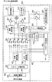
図1は、本発明の実施の形態1に係る音声信号伝送システムの構成を示すブロック図である。
【0059】
音声信号伝送システムは、音声信号送信装置100及び音声信号受信装置199を具備している。
【0060】
音声信号送信装置100は、入力装置102、A/D変換装置103、音声符号化装置104、信号処理装置105、RF変調装置106、送信装置107及びアンテナ108を有している。A/D変換装置103は入力装置102に接続されている。
【0061】
音声符号化装置104の入力端子はA/D変換装置103の出力端子に接続されている。信号処理装置105の入力端子は、音声符号化装置104の出力端子に接続されている。RF変調装置106の入力端子は信号処理装置105の出力端子に接続されている。送信装置107の入力端子はRF変調装置106の出力端子に接続されている。アンテナ108は、送信装置107の出力端子に接続されている。
【0062】
入力装置102は、音声信号を受けてこれを電気信号であるアナログ音声信号に変換し、A/D変換装置103に与える。A/D変換装置103は、入力装置102からのアナログの音声信号をディジタル音声信号に変換し、これを音声符号化装置104に与える。音声符号化装置104は、A/D変換装置103からのディジタル音声信号を符号化して音声符号化情報を生成し信号処理装置105に与える。
【0063】
信号処理装置105は、音声符号化装置104からの音声符号化情報にチャネル符号化処理、パケット化処理及び送信バッファ処理等を行った後、その音声符号化情報をRF変調装置106に与える。RF変調装置106は、信号処理装置105からの音声符号化信号を変調して送信装置107に与える。送信装置107は、RF変調装置106からの音声符号化信号をアンテナ108を介して電波(RF信号)として送信する。
【0064】
音声信号送信装置100においては、A/D変換装置103を介して得られるディジタル音声信号に対して数十msのフレーム単位で処理が行われ、1フレーム又は数フレームの符号化データを1つのパケットに入れこのパケットをパケット網に送出する。本実施の形態では、伝送遅延を最小限にするために、1フレームを1パケットで伝送することを想定している。したがって、パケット損失はフレーム消失に相当する。
【0065】
なお、本発明はパケット交換網に限らず、回線交換網にも適用可能で、その場合は、パケット化処理、ジッタ吸収バッファリング処理及びパケット組みたて処理は不要である。
【0066】
音声信号受信装置199は、アンテナ110、受信装置111、RF復調装置112、信号処理装置113、音声復号化装置114、D/A変換装置115及び出力装置116を有している。受信装置111の入力端子は、アンテナ110に接続されている。RF復調装置112の入力端子は、受信装置111の出力端子に接続されている。信号処理装置113の入力端子は、RF復調装置112の出力端子に接続されている。音声復号化装置114の2つの入力端子は、信号処理装置113の2つの出力端子に一対一接続されている。D/A変換装置115の入力端子は、音声復号化装置114の出力端子に接続されている。出力装置116の入力端子は、D/A変換装置115の出力端子に接続されている。
【0067】
受信装置111は、アンテナ110を介して音声符号化情報である電波(RF信号)を受けてアナログの電気信号である受信音声信号を生成し、これをRF復調装置112に与える。アンテナ110を介して受けた電波(RF信号)は、伝送路において信号の減衰や雑音の重畳がなければ、音声信号送信装置100において送信された電波(RF信号)と全く同じものとなる。
【0068】
RF復調装置112は、受信装置111からの受信音声信号を復調し信号処理装置113に与える。信号処理装置113は、RF復調装置112からの受信音声信号のジッタ吸収バッファリング処理、パケット組みたて処理、パケット消失検出処理、多重分離処理及びチャネル復号化処理等を行って受信音声信号とパケット消失情報とをそれぞれ音声復号化装置114に与える。
【0069】
音声復号化装置114は、信号処理装置113からの受信音声信号を復号化して復号音声信号を生成しD/A変換装置115に与える。D/A変換装置115は、音声復号化装置114からのディジタル復号音声信号をアナログ復号音声信号に変換して出力装置116に与える。出力装置116は、D/A変換装置115からのアナログ復号音声信号を空気の振動に変換し音波として人間の耳に聴こえるように出力する。
【0070】
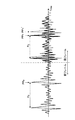
次に、音声符号化装置104について図1、図2及び図3を参照して詳細に説明する。図2は音声符号化装置104の構成を示すブロック図である。図3は、ピッチピーク位置検出部の動作を説明するための模式図である。
【0071】
図1に示すように、音声符号化装置104は、ピッチピーク位置検出部151、多重化部152、音声符号化部153及び1フレーム遅延部154を有している。音声符号化部153の入力端子は、A/D変換装置103の出力端子に接続されている。ピッチピーク位置検出部151の入力端子は、音声符号化部153の2つの出力端子のうちの一方に接続されている。1フレーム遅延部154の入力端子は音声符号化部153の2つの出力端子のうちのもう一方に接続されている。多重化部152は、ピッチピーク位置検出部151及び1フレーム遅延部154の出力端子と信号処理装置105の入力端子との間に接続されている。
【0072】
音声符号化部153は、A/D変換装置103から入力したディジタル音声信号の符号化処理を行い、符号化パラメータ情報を1フレーム遅延部154へ出力する。同時に、音声符号化部153は、後述するピッチパラメータ(量子化ピッチ周期)と適応符号帳に保持されている音源信号とをピッチピーク位置検出部151へ出力する。ピッチピーク位置検出部151は、ピッチパラメータである量子化ピッチ周期情報と過去の音源信号系列とを用いて、過去1ピッチ周期長の音源信号におけるピッチピーク位置を検出し、多重化部152へ出力する。
【0073】
なお、ピッチピーク位置は現在のフレームの最後尾から過去に1ピッチ周期分だけさかのぼった範囲の中に存在する、フレーム最後尾に最も近いものとする。したがって、1フレームが複数のサブフレームに分割されている場合は、最後のサブフレームにおいてピッチピーク位置検出を行う。また、ピッチ周期が長く、現フレーム中にピッチピークが存在しない場合でも、現フレーム末尾の点から1ピッチ周期の範囲内でピッチピーク位置を探索して直前フレーム区間にあるピッチピーク位置を検出することとする。
【0074】
多重化部152は、ピッチピーク位置検出部151によって検出された現フレームにおけるピッチピーク位置情報と、1フレーム遅延部154から出力される前フレームにおける音声符号化情報とを多重化し、信号処理装置105へ出力する。
【0075】
次に、音声符号化部153について、図2を用いてより詳細に説明する。音声符号化部153は、図2に示されるように、前処理部201、線形予測係数を求める線形予測分析器202、線形予測係数の量子化及び符号化を行うLPC量子化器203、聴覚重みフィルタ204、聴覚重みフィルタ205、量子化された線形予測係数によって構成される線形予測フィルタとしてのLPC合成フィルタ206、加算器207、適応符号帳208、乗算器209、固定符号帳210、乗算器211、利得量子化器212、加算器213、音源パラメータ決定部214および符号化部215とを有している。適応符号帳208、固定符号帳210及び利得量子化器212によって音源符号化部が構成され、この音源符号化部によってLPC合成フィルタ206が駆動される。
【0076】
前処理部201は、A/D変換装置103(図1)からディジタル音声信号を入力し、背景雑音抑圧処理やプリエンファシス処理のように音声の品質を改善するための処理やDC成分をカットするためのハイパスフィルタ処理などを行って線形予測分析器202と聴覚重みフィルタ204とに出力する。線形予測分析器202は、前処理部201から入力した前処理後のディジタル音声信号の線形予測分析を行って線形予測係数を算出し、LPC量子化器203と聴覚重みフィルタ204と聴覚重みフィルタ205とにそれぞれ出力する。
【0077】
LPC量子化器203は、線形予測分析器202から入力した線形予測係数の量子化・符号化処理を行い、量子化した線形予測係数をLPC合成フィルタ206に出力するとともに符号化結果をパラメータLとして出力する。パラメータLは符号化部215に入力され、他の符号化音源パラメータとともにまとめて符号化される。聴覚重みフィルタ204と聴覚重みフィルタ205は、線形予測分析器202によって算出された線形予測係数を用いたARMA型のディジタルフィルタで、後述する音声符号化部による量子化誤差に対して人間の聴覚特性に合わせた重み付けをするためのものであり、2つの聴覚重みフィルタ204及び205は同じフィルタ特性を有する。
【0078】
聴覚重みフィルタ204は、前処理部201から前処理後のディジタル音声信号を入力し、聴覚重み付けをするARMAフィルタ処理を行って加算器213へ出力する。聴覚重みフィルタ205は、LPC合成フィルタ206によって合成されたディジタル音声信号を入力し、同じ聴覚重み付けをするARMAフィルタ処理を行って加算器213へ出力する。
【0079】
LPC合成フィルタ206は、LPC量子化器203によって量子化された線形予測係数を用いて構成されるAR型のディジタルフィルタであり、加算器207から出力された音源信号を用いて合成音声信号を生成し、聴覚重みフィルタ205へ出力する。加算器207は、適応符号帳208から乗算器209を介して入力した適応符号帳ベクトルと、固定符号帳210から乗算器211を介して入力した固定符号帳ベクトルとのベクトル加算を行って、音源ベクトルを生成し、LPC合成フィルタ206へ出力する。また、生成した音源ベクトルは、適応符号帳208へフィードバックされて、適応符号帳208の内容が更新される。更新後の適応符号帳の音源信号バッファは、ピッチピーク位置検出部151へ出力される。
【0080】
適応符号帳208は、加算器207によって過去に生成された音源ベクトルを蓄積・保持しているメモリであり、加算器207から出力された音源ベクトルによって逐次更新される。また、適応符号帳208は、適正な位置からベクトルを切り出して乗算器209へ出力する。有声信号の場合、音源信号が周期性を有することから、過去に生成した音源信号を利用して効率的に音源信号を符号化することができることから、このような適応符号帳が一般に用いられる。適応符号帳ベクトルの切りだし位置はピッチパラメータPによって決定される。ピッチパラメータPは、音源パラメータ決定部によって決定される。
【0081】
固定符号帳210は、雑音系列や少数のパルスの組み合わせなどによって任意のベクトルを生成するもので、予め定められた数のベクトルを格納もしくは生成できるようになっており、各ベクトルには固有の番号が振られており、その番号を指定することで対応する形状の固定符号帳ベクトルが生成される。番号は固定符号帳インデックスCとして、音源パラメータ決定部214で決定される。
【0082】
なお、図2では示していないが、固定符号帳は複数のチャンネルや複数のサブセットから構成されていたり、固定符号帳ベクトルに対してピッチ周期化処理が行われたりすることが一般的である。
【0083】
乗算器209は、利得量子化器212によって量子化された適応符号帳利得(ピッチ利得)を、適応符号帳208から出力されたベクトルに乗じて加算器207へ出力する。乗算器211は、利得量子化器212によって量子化された固定符号帳利得を固定符号帳210から出力されたベクトルに乗じて加算器207へ出力する。
【0084】
利得量子化器212は、音源利得パラメータGで示される量子化適応符号帳利得および量子化固定符号帳利得をそれぞれ乗算器209及び211へ出力する。音源利得パラメータGは音源パラメータ決定部214で決定される。音源パラメータ決定部214は、加算器213から出力される、聴覚重みフィルタ204によって聴覚重み付けされた入力音声信号と聴覚重みフィルタ205によって聴覚重み付けされたLPC合成フィルタ206の合成音声信号との出力の誤差を最小化するように、適応符号帳パラメータPと固定符号帳パラメータCと利得パラメータGを決定する。
【0085】
加算器213は、聴覚重みフィルタ205からの出力ベクトルと聴覚重みフィルタ204からの出力ベクトルとの差分ベクトルを算出して音源パラメータ決定部214へ出力する。音源パラメータ決定部によって決定された適応符号帳パラメータPと固定符号帳パラメータCと利得符号帳パラメータGと、LPC量子化器203によって符号化された線形予測パラメータLとは、符号化部215により一括して一つの符号としてまとめられ、1フレーム遅延部154へ出力される。1フレーム遅延部154は、符号化部215より入力した音声符号化情報を1フレームの時間だけ保持した後、多重化部152へ出力する。
【0086】
次に、ピッチピーク位置検出部151の動作について、図3を参照してより詳細に説明する。
【0087】
図3に示すように、ピッチピーク位置検出部151は、ピッチパラメータPと、最新の適応符号帳の内容(過去に生成した音源信号系列)を少なくとも1ピッチ周期長以上を入力し、最も時間的に後ろにあるピッチピーク位置を検出する。ピッチピーク位置の検出法の最も単純なものは、適応符号帳の末尾(最新のサンプル:図3は1101)から過去に1ピッチ周期Pまでさかのぼる間において、絶対値が最大となるサンプル(図3は1102)をピッチピーク位置として検出する方法である。なお、現在の入力音声信号にピッチ周期性がない場合(無声部や雑音部である場合)には、ピッチピーク位置を無理に設定せず、ピッチ周期性がない区間であることを示すコードを別途割り当てて、その情報をピッチピーク位置情報として出力する。
【0088】
次に、音声復号化装置114について図1、図4、図5〜図7を参照して詳細に説明する。図4は送信パケットの略線図、図5は音声復号化装置114の構成を示すブロック図、図6〜図8はフレーム消失補償処理を説明するための概念図である。
【0089】
図1に示すように、音声復号化装置114は、多重分離部155、音声復号化部156、1フレーム遅延部157及びフレーム消失補償部158を有している。
【0090】
多重分離部155の入力端子は信号処理装置113の2つの出力端子の一方に接続されている。音声復号化部156は3つの入力端子を持ち、第1の入力端子は多重分離部155の1つの出力端子に、第2の入力端子は信号処理装置113の1つの出力端子に、第3の入力端子はフレーム消失補償部158に、それぞれ接続されている。また、音声復号化部156は2つの出力端子をもち、一方はフレーム消失補償部158の2つの入力端子の一方に接続されており、他方はD/A変換装置115へ接続されている。1フレーム遅延部157の入力端子は、多重分離部155の出力端子の一つに接続されている。フレーム消失補償部158は2つの入力端子をもち、一方は1フレーム遅延部157の出力端子に接続されており、他方は音声復号化部156の1つの出力端子に接続されている。
【0091】
多重分離部155は、信号処理装置113から入力した多重化情報を、音声符号化情報とピッチピーク位置情報とに分離し、音声復号化部156と1フレーム遅延部157とにそれぞれ出力する。また、信号処理装置113は、フレーム消失情報を音声復号化部156へ出力する。音声復号化部156は、多重分離部155から入力した音声符号化情報を用いて復号処理を行い、復号音声信号をD/A変換装置115へ出力する。また、フレーム消失補償処理において更新が必要なパラメータをフレーム消失補償部158へ出力する。
【0092】
なお、音声復号化部156において、信号処理装置113から出力されたフレーム消失補償情報が「現在のフレームは消失している」ことを示す場合は、多重分離部155からの情報が入力されないので、フレーム消失補償部158から入力されるパラメータ情報を用いて音声信号を生成し、D/A変換装置115へ出力する。このときもフレーム消失補償処理において更新が必要なパラメータはフレーム消失補償部158へ出力される。1フレーム遅延部157は、多重分離部155より入力したピッチピーク位置情報を1フレーム分の時間だけ保持してからフレーム消失補償部158へ出力する。フレーム消失補償部158は、1フレーム遅延部157から出力された、現フレーム(1フレーム前に送られてきているピッチピーク位置情報は、1フレーム前において1フレーム先のピッチピーク位置情報なので、現フレームのピッチピーク位置情報である)におけるピッチピーク位置情報を入力し、現フレームにおけるピッチピーク位置が入力されたピッチピーク位置情報で示される位置に合うようにフレーム消失補償処理を行う。フレーム消失補償処理は、1フレーム遅延部157から入力した現フレームの最後尾ピッチピーク位置と、音声復号化部156から入力した前フレームまでに復号している音声符号化パラメータとを用いて行われる。
【0093】
因みに、音声復号化装置114において、1フレーム遅延部157から出力されたピッチピーク位置情報が、現フレームにおけるピッチピーク位置である理由を図4を参照しながら説明する。
【0094】
図4は、音声符号化装置104において符号化された各フレームの音声符号化情報とピッチピーク位置情報とをパケット化して送信する際の説明に供する略線図である。図4に示すように、音声符号化装置104では、符号化されてなる音声符号化情報を1フレーム分遅延させるとともに、ピッチピーク位置情報は遅延させることなく、多重化している。
【0095】
従って、図4において、例えばフレームf2のピッチピーク位置情報1001pは、遅延なく第1のパケット1001によって送信されるのに対して、そのフレームf2の音声符号化情報1002aは1フレーム遅延し、次のフレームf3のピッチピーク位置情報1002pとともにパケット1002によって送信される。
【0096】
このようにして音声符号化装置104(音声信号送信装置100)から送信されたパケット化された音声符号化情報及びピッチピーク位置情報は、音声信号受信装置199の音声復号化部156において復号される。この場合、例えばパケット1001によって送信された、フレームf2のピッチピーク位置情報1001pは、送信側で1フレーム遅延されて送信されたフレームf2の音声符号化情報1002aがパケット1002によって到来するのを待って処理される。
【0097】
次に、音声復号化部156について、図5を参照してより詳細に説明する。音声復号化部156は、図5に示されるように、パラメータ復号部301、利得復号器302、切り替えスイッチ303、適応符号帳304、固定符号帳305、線形予測係数の復号処理を行うLPC復号器306、乗算器307、乗算器308、加算器309、LPC復号器306において復号された線形予測係数によって構成される線形予測フィルタであるLPC合成フィルタ310及び後処理部311を有する。適応符号帳304、固定符号帳305及び利得復号器302によって音源復号部が構成され、この音源復号部によってLPC合成フィルタ310を駆動する。
【0098】
パラメータ復号器301の入力端子は多重分離部155の出力端子の1つに接続されている。利得復号器302の入力端子はパラメータ復号部301の出力端子の一つに接続されている。LPC復号器306の入力端子はパラメータ復号部301の出力端子の一つに接続されている。切り替えスイッチ303の入力端子はパラメータ復号部301の出力端子と利得復号器の出力端子とLPC復号器306の出力端子とフレーム消失補償部の出力端子にそれぞれ接続されている。また、切り替えスイッチ303のフレーム消失情報を受信する端子が、信号処理装置113(図1)に接続されている。適応符号帳304の入力端子は、スイッチ303の出力端子と加算器309の出力端子に接続されている。
【0099】
固定符号帳305の入力端子は、切り替えスイッチ303の出力端子に接続している。乗算器307の2つの入力端子は、一方が適応符号帳304の出力端子に、他方が切り替えスイッチ303の出力端子にそれぞれ接続している。乗算器308の2つの入力端子は、一方が固定符号帳305に、他方が切り替えスイッチ303の出力端子に、それぞれ接続している。加算器309の2つの入力端子は、一方が乗算器307の出力端子に、他方が乗算器308の出力端子に、それぞれ接続されている。LPC合成フィルタ310の2つの入力端子は、一方が加算器309に、他方が切り替えスイッチ303に、それぞれ接続している。後処理部311の入力端子は、LPC合成フィルタ310の出力端子に接続しており、ディジタル復号音声信号をD/A変換装置115へ出力する。
【0100】
パラメータ復号部301は、多重分離部155から入力した音声符号化情報(ビットストリーム)から音声符号化パラメータ(ピッチ(適応符号帳)パラメータP、固定符号帳パラメータC、線形予測パラメータL、利得パラメータG)を復号し、利得パラメータGを利得復号器302へ、線形予測係数パラメータLをLPC復号器306へ、その他のパラメータを切り替えスイッチ303へそれぞれ出力する。
【0101】
利得復号器302は、パラメータ復号部301から入力した利得パラメータGから適応符号帳利得Gpと固定符号帳利得Gcをそれぞれ復号し、切り替えスイッチ303へ出力する。LPC復号器306は、パラメータ復号部301から入力した線形予測係数パラメータLから復号量子化線形予測係数αを復号し、切り替えスイッチ303へ出力する。切り替えスイッチ303は、パラメータ復号器301、利得復号器302およびLPC復号器306から入力されるパラメータ群と、フレーム消失補償部158から入力されるパラメータ群との切替を行うためのスイッチで、信号処理装置113(図1)から受信したフレーム消失情報が「現フレームは消失フレームである」を示す場合にはフレーム消失補償処理部158が生成したパラメータ側にスイッチが切り替わり、それ以外の場合はパラメータ復号部301、利得復号器302およびLPC復号器306から出力されるパラメータ側にスイッチが接続される。
【0102】
切り替えスイッチ303は、適応符号帳パラメータ(ピッチ)PまたはP'を適応符号帳304へ、適応符号帳利得GpまたはGp'を乗算器307へ、固定符号帳パラメータCまたはC'を固定符号帳305へ、固定符号帳利得GcまたはGc'を乗算器308へ、復号量子化線形予測係数αまたはα'をLPC復号器306へ、それぞれ出力する。また、切り替えスイッチ303は、適応符号帳304、固定符号帳305、乗算器307、乗算器308、LPC合成フィルタ310へ出力した各パラメータをフレーム消失補償部158にも同時に出力する。
【0103】
適応符号帳304は、過去に生成された音源信号をバッファリングしており、加算器309から最新の音源信号が入力されるたびに更新される。適応符号帳304のバッファリングしている信号長は、最大ピッチ周期長+フレーム長以上である。切り替えスイッチ303から入力した適応符号長パラメータ(ピッチ)PまたはP'によって指定される位置から適応符号帳ベクトルを切り出して乗算器307へ出力するとともに、1フレーム前以前の音源信号をフレーム消失補償処理部158へ出力する。乗算器307は、適応符号帳304から出力された適応符号ベクトルに、切り替えスイッチ303から入力した適応符号帳利得GpまたはGp'を乗じて加算器309へ出力する。
【0104】
固定符号帳305は、切り替えスイッチ303から入力した固定符号帳パラメータCまたはC'によって指定される固定符号帳ベクトルを生成し、乗算器308へ出力する。乗算器308は、固定符号帳305から入力した固定符号帳ベクトルに、切り替えスイッチ303から入力した固定符号帳利得GcまたはGc'を乗じて加算器309へ出力する。加算器309は、乗算器307から入力した適応符号帳ベクトルと、乗算器308から入力した固定符号帳ベクトルとを加算し、LPC合成フィルタ310および適応符号帳304へ出力する。
【0105】
LPC復号器306は、パラメータ復号部301によって復号された線形予測パラメータLから復号量子化線形予測係数αを切り替えスイッチ303に出力する。LPC合成フィルタ310は、切り替えスイッチ303から入力した復号量子化線形予測係数αまたはα'によって構成されるAR型ディジタルフィルタを、加算器309より入力する音源信号によって駆動し、合成音声信号を後処理部311へ出力する。後処理部311は、音声信号の主観品質を改善するためのホルマント強調ポストフィルタ処理、ピッチ強調ポストフィルタ処理、傾斜補正ポストフィルタ処理、及び、背景雑音信号の主観品質を改善するための雑音後処理、を行い、これらの処理が施されたディジタル復号音声信号をD/A変換装置115へ出力する。
【0106】
次に、フレーム消失補償部158について、図5、図6〜図8を参照しながら詳細を説明する。フレーム消失補償部158は、パラメータバッファ312、ピッチピーク位置検出器313、ピッチ周期算出器314及びパラメータ生成部315を有する。
【0107】
パラメータバッファ312の入力端子は、音声復号化部156内の切り替えスイッチ303に接続されている。ピッチピーク位置検出器313の2つの入力端子は、一方が音声復号化部の適応符号帳304に、他方はパラメータバッファ312の出力端子の一つ(ピッチ情報を入力)に、それぞれ接続されている。
【0108】
ピッチ周期算出器314の3つの入力端子は、一つがピッチピーク位置検出器313に、もう一つが1フレーム遅延部157に、残りの一つがパラメータバッファ312の出力端子の一つ(ピッチ情報を入力)に、それぞれ接続されている。パラメータ生成部315の6つの入力端子は、5つがパラメータバッファ312の5つの出力端子に接続されており、残りの1つがピッチ周期算出器314に、それぞれ接続されている。
【0109】
パラメータバッファ312は、過去に音声復号化部156において、復号音声を生成するために用いられた各種の音声符号化パラメータを記憶しておくバッファであり、復号した適応符号帳パラメータ(ピッチ)P、雑音符号帳パラメータC、適応符号帳利得Gp、固定符号帳利得Gc、復号量子化線形予測係数αが音声復号化部156から入力される。また消失フレームにおいては、パラメータ生成部によって生成されたパラメータ(適応符号帳パラメータ(ピッチ)P'、固定符号帳パラメータC'、適応符号帳利得Gp'、固定符号帳利得Gc'、復号量子化線形予測係数α')が入力される。
【0110】
バッファリングされている各種パラメータは、パラメータ生成部315へ出力され、消失フレームにおける各種パラメータを生成する際に使用される。ピッチピーク位置検出器313は、音声復号化部156内の適応符号帳304から入力した音源信号と、パラメータバッファ312から入力した前フレームのピッチ周期とを用いて、ピッチピーク位置検出部151(図1)と同様にしてピッチピーク位置を検出し、ピッチ周期算出器314へ出力する。ただし、ピッチピーク位置を探す範囲は直前のフレーム以前において生成された音源信号の部分であり、ピッチピーク位置が存在する範囲は前フレームで生成された音源信号の末尾の点から、前フレームのピッチ周期だけさかのぼった点までである。
【0111】
ピッチ周期算出器314は、ピッチピーク位置検出器313から入力した前フレームの最終ピッチピーク位置と、1フレーム遅延部157から入力した現フレームの最終ピッチピーク位置(1フレーム遅延部から出力されるのは、1フレーム前に受信したピッチピーク位置情報であり、1フレーム前に送られてきているピッチピーク位置情報は、現在復号している(消失補償処理を行っている)音声フレームに対応するピッチピーク位置情報である)と、パラメータバッファ312から入力した前フレームにおける音声復号部で復号されたピッチ周期と、を入力し、現在のピッチ周期を求める。具体的には、(式1)によって現フレームのピッチ周期を決定することが出来る。
【0112】
Pc = (N(PPc)+Nf−N(PPp))÷Int[0.5+(N(PPc)+Nf−N(PPp))/Pp] (式1)
但し、PPcは現フレームにおける最終ピッチピーク位置(1フレーム遅延部157から入力した情報によって得られる)、PPpは前フレームにおける最終ピッチピーク位置(ピッチピーク位置検出器313から入力した情報によって得られる)、Ppは前フレームにおけるピッチ周期(パラメータバッファ312より入力)、N(PPx)はフレームXにおけるピッチピーク位置PPxをフレームXの先頭からの距離で表した場合の数値、Nfはフレーム長、をそれぞれ示す。また、Int[]は演算結果を越えない最大の整数を示す。
【0113】
例えば、図6に示すようなフレーム消失のケースを考える。図6では現フレームが消失し、前フレームのピッチ周期を用いて、前フレームの波形を繰り返す消失補償処理を行った場合を示している。このとき、フレーム消失補償によって生成される現フレームの波形における最終ピッチピーク位置はPPc'である。
【0114】
ところで、図7のように、実際には現フレームにおいてピッチ周期が短くなっていた場合、実際のピッチピーク位置PPcと図6のようなフレーム消失補償処理を行った場合のピッチピーク位置PPc'との間にずれが生じてしまう。このようなずれは、消失した現フレームのみならず、後続の正常受信フレームにおいて適応符号帳のピッチピーク位置が符号器側と復号器側とでずれてしまうため、復号音声品質の劣化が大きくなる。
【0115】
しかしながら、消失したフレームにおけるピッチピーク位置情報が前フレームの音声符号化パラメータとともに伝送されていれば、消失した現フレームにおけるピッチピーク位置PPcが合うように、ピッチ周期Pcを(式1)の様にして決定することができる。ピッチの量子化精度によっては、同一ピッチ周期で繰り返してもピッチピーク位置を合わせることが出来ない場合もあるので、(式1)で求められるピッチ周期Pc付近のピッチ量子化値を用いて段階的にピッチ周期Pcを変化させてピッチピーク位置を合わせることも可能である。
【0116】
なお、ピッチピーク位置におけるピーク値の極性が合わないことが問題になる場合は、極性情報もピッチピーク位置情報として伝送するようにして利用する。
【0117】
フレーム消失補償部158において、このようにしてピッチ周期Pcを求め、そのピッチ周期Pcを用いてフレーム消失補間処理を行った例を図8に示す。フレーム消失がなかった場合の復号信号(破線)に比べて波形レベルでは一致しないものの、ピッチピーク位置を一致させることが出来るので、後続フレームにおける符号器側と復号器側の適応符号帳間不一致の影響を低減することが可能となる。また、ピッチピーク位置情報だけを送るので、ビットレートの増加も少ない。たとえばIETF標準のRFC2198(Perkinsら、"RTP PayloA/D for RedunD/Ant Audio D/Ata", Sept. 1997)などで規定されているようにプライマリコーデック情報とセカンダリコーデック情報とを伝送するのに比べると、低ビットレートでのFEC(Forward Error Correction:前方誤り訂正)を実現することが可能である。
【0118】
なお、現フレームのピッチピーク位置情報が「現フレームはピッチ周期性を有していないフレームである」ことを示している場合は、ピッチ周期算出器314は、上述のようなピッチ周期の計算は行わず、現フレームがピッチ周期性を有さないフレームであることを示す情報をパラメータ生成部に出力する。
【0119】
パラメータ生成部315は、ピッチ周期算出器314で算出されたピッチ周期と、パラメータバッファ312から入力した前フレームにおける各種復号パラメータを用いて消失したフレームの音源パラメータを生成する。例えば、ピッチ周期算出器314から入力した情報が、「現フレームはピッチ周期性を有さないフレームである」ことを示している場合は、パラメータ生成部315は、適応符号帳利得Gp'を0.0とし、ランダムに生成した固定符号帳パラメータC'と前フレームにおいて使用した固定符号帳利得を減衰させた値をGc'として切り替えスイッチ303へ出力する。反対に、ピッチ周期算出器314から入力した情報が「現フレームはピッチ周期性を有し、そのピッチ周期はPc'である」ことを示している場合は、パラメータ生成部315は、ピッチパラメータをPc'に設定し、適応符号帳利得Gp'を前フレームで復号した適応符号帳利得GpやGpを減衰した値(例えば0.9倍した値)や過去に復号したGpの平均的な値などに設定し、固定符号帳利得Gc'を0.0に設定して、切り替えスイッチ303へそれぞれ出力する。なお、復号量子化線形予測係数α'としては、前フレームにおける復号量子化線形予測係数が繰り返して使用されたり、又は帯域幅を拡張してスペクトル特性を平坦化したものが使用される。
【0120】
次に、音声符号化装置104および音声復号化装置114の動作について、図9及び図10を参照して説明する。図9は、音声符号化装置104の動作を説明するためのフロー図であり、図10は、音声復号化装置114の動作を説明するためのフロー図である。
【0121】
図9に示すように、音声符号化装置104は、まずステップST101において、音声符号化部153により1フレーム分のCELP音声符号化処理を行い、次に、ステップST102において、ステップST101にて得られた音声符号化情報を次のフレームの処理が終わるまで1フレーム遅延部154によって保存する。
【0122】
次に、音声符号化装置104は、ステップST103において、ピッチピーク位置検出部151によって、現フレームにおいて一番後ろにあるピッチピーク位置の検出を行う。
【0123】
次に、音声符号化装置104は、ステップST104において、ステップST102にて保存された前フレームの音声符号化情報(前フレームの音声符号化情報)を1フレーム遅延部154から取り出した後、ステップST105に移って、ステップST104において取り出された前フレームの音声符号化情報と、ステップST103にて検出されたピッチピーク位置情報とを多重化部152によって多重化し、これを音声符号化装置104の出力として出力する。
【0124】
音声符号化装置104は、上述したステップST101〜ステップST105の一連の符号化処理を繰り返す。
【0125】
続いて音声復号化装置114の動作を説明する。図10に示すように、音声復号化装置114は、まず、ステップST110において、現フレームが消失しているかどうかを信号処理装置113によって判定する。消失していない場合はステップST111に移り、また、消失している場合はステップST114に移る。
【0126】
次に、フレーム消失していない場合は、ステップST111において、多重分離部155が受信した多重化情報を分離する。
【0127】
続いて、ステップST112において、音声復号化部156内のパラメータ復号部301が、分離された音声符号化情報から音声符号化パラメータを復号する。次に、ステップST113において、音声復号化部156の残りの部分が、復号された音声符号化パラメータから音声信号を再合成する処理を行い、復号音声信号がD/A変換装置115へ出力される。
【0128】
これに対して、ステップST110においてフレームが消失していると判断された場合は、音声復号化装置114は、ステップST114に移って、ピッチ周期算出器314によって、現フレーム(消失フレーム)がピッチ周期性を有するフレームであるか否かをチェックする。ピッチ周期性があるか否かに関する情報は受信したピッチピーク位置情報に含まれている。音声復号化装置114は、ピッチ周期性がある場合はステップST115へ移り、ピッチ周期性がない場合はステップST118へ移る。そして、現フレーム(消失フレーム)がピッチ周期性を有する場合、音声復号化装置114は、ステップST115に移って、ピッチピーク位置検出器313によって、前フレームのピッチ情報と復号した音源信号とを、パラメータバッファ312と適応符号帳304から、それぞれ読み出す。
【0129】
次に、音声復号化装置114は、ステップST116に移って、ピッチピーク位置検出器313によって、前フレームにおいて最も後ろにあるピッチピーク位置を検出する。なお、パラメータバッファ312が、2つ前に受信したピッチピーク位置情報を保持している場合は、その情報を用いて前フレームにおけるピッチピーク位置を得ても良い。
【0130】
次に、音声復号化装置114は、ステップST117に移って、ピッチ周期算出器314によって、現フレーム(消失フレーム)のピッチピーク位置と前フレームのピッチピーク位置と前フレームのピッチ周期を用いて、上述の(式1)によってピッチ周期を算出する。
【0131】
次に、音声復号化装置114は、ステップST118に移って、消失したフレームにおける各種音声符号化パラメータをパラメータ生成部315によって生成する。
【0132】
現フレームがピッチ周期性を有するフレームであると判断された場合は、固定符号帳利得をゼロとし、適応符号帳のみを用いて音声信号を生成する。このとき用いるピッチ周期(適応符号帳パラメータ)は、ピッチ周期算出器314にて算出されたものを用いる。また、現フレームがピッチ周期性をもたないフレームであると判断された場合は、音声復号化装置114は、適応符号帳利得をゼロとし、固定符号帳のみで音声信号を生成する。この場合、固定符号帳パラメータはランダムに決定する。線形予測係数については、現在フレームのピッチ周期性の有無に関らず、前フレームのものを繰り返し利用するか、又は、帯域幅拡張を行いながら次第に白色化したものを用いる。
【0133】
最後に、音声復号化装置114は、ステップST119において、パラメータバッファ312の内容を更新して、1フレームの復号処理を終了する。
【0134】
音声復号化装置114は、上記ステップST110〜ステップST119の一連の復号処理を繰り返す。
【0135】
このように、本実施の形態の音声信号送信装置100及び音声信号受信装置199によれば、少ない冗長情報の追加で、精度良いフレーム消失補償処理が可能となるとともに、ピッチピーク位置が合わせられることにより、ピッチピーク位置のずれが消失フレーム後に伝搬されることを回避することができ、この結果、消失フレーム後の誤り伝播の影響を軽減することができる。
【0136】
(実施の形態2)
図11は、本発明の実施の形態2に係る音声信号伝送システムの構成を示すブロック図である。
【0137】
図11に示す音声信号伝送システムは、音声信号送信装置400及び音声信号受信装置499を有している。
【0138】
音声信号送信装置400は、実施の形態1の音声信号送信装置100における音声符号化装置104を音声符号化装置404に置き換えたものである。実施の形態1と同じ構成要素で同じ動作をするものについては、実施の形態1と同一符号を付し、詳しい説明を省略する。
【0139】
音声符号化装置404は、A/D変換装置103からのディジタル音声信号を符号化することにより音声符号化情報を生成し、この生成された音声符号化情報を信号処理装置105に与える。
【0140】
音声信号受信装置499は、実施の形態1の音声信号受信装置199における音声復号化装置114を音声復号化装置414に置き換えたものである。実施の形態1と同じ構成要素で同じ動作をするものについては、実施の形態1と同一符号を付し、詳しい説明を省略する。音声復号化装置414は、信号処理装置113からの受信音声信号を復号化して復号音声信号を生成してD/A変換装置115に与える。
【0141】
次に、図11および図12を参照して音声符号化装置404の詳細について説明する。
【0142】
図11および図12に示した音声符号化装置404において、図1および図2に示した実施の形態1の音声符号化装置104と同じ動作をする同じ構成要素については、実施の形態1と同一符号を付し、詳しい説明を省略する。
【0143】
1フレーム遅延部452の入力端子は、ピッチピーク位置検出部151の出力端子に接続されている。多重化部454の2つの入力端子は、一方が1フレーム遅延部452の出力端子に、他方が音声符号化部153の出力端子に、それぞれ接続されている。
【0144】
1フレーム遅延部452は、ピッチピーク位置検出部151から出力された、現フレームにおける最も後ろにあるピッチピーク位置情報を、1フレームの時間だけ保持してから多重化部454へ出力する。多重化部454は、1フレーム遅延部452から入力した1フレーム前における前記ピッチピーク位置情報と、音声符号化部153から入力した現フレームの符号化音声情報と、を多重化して一つにまとめた符号化情報としてD/A変換装置115へ出力する。
【0145】
すなわち、実施の形態1と実施の形態2との違いは、ピッチピーク位置情報と音声符号化情報のどちらを1フレーム遅延させて多重化させるかの違いである。ピッチピーク位置情報を遅延させるのが実施の形態2であり、音声符号化情報を遅延させるのが実施の形態1である。実施の形態1と実施の形態2の音声符号化装置におけるその他の動作は全て同じである。
【0146】
因みに、図13は、音声符号化装置404において、符号化された各フレームの音声符号化情報とピッチピーク位置情報とをパケット化して送信する際の説明に供する略線図である。図13に示すように、音声符号化装置404では、ピッチピーク位置情報を1フレーム分遅延させるとともに、音声符号化情報は遅延させることなく、多重化している。
【0147】
従って、図13において、例えばフレームf2の音声符号化情報2001aは、遅延なく第1のパケット2001によって送信されるのに対して、そのフレームf2のピッチピーク位置情報2002pは1フレーム遅延し、次のフレームf3の音声符号化情報2002aとともにパケット2002によって送信される。
【0148】
このようにして音声符号化装置404(音声信号送信装置400)から送信されたパケット化された音声符号化情報及びピッチピーク位置情報は、音声信号受信装置499の音声復号化部456において復号される。この場合、例えばパケット2002によって送信された、フレームf2のピッチピーク位置情報2002pは、送信側で1フレーム遅延されて送信されていることにより、音声復号化部456において復号される際には、前フレームのピッチピーク位置情報となる。音声復号化部456では、フレーム消失情報に基づいて現在復号しようとするフレームの音声符号化情報が消失している場合には、前フレームで復号した音声符号化情報を用いて、フレーム消失補償部457によって一般的なフレーム消失補償を行う。また、前フレームが消失フレームであった場合は、音声復号化部456の1フレーム遅延部601(後述)によって、その前フレームにおけるフレーム消失情報を1フレーム分だけ遅延させることにより、消失した前フレームに続く現在フレームにおいて、このフレーム消失情報によって適応符号帳修正器603(後述)を動作させる。これにより、前フレームにおいてフレーム消失補償部457によって補償されたパラメータに基づいて生成された適応符号帳304が修正される。
【0149】
次に、図11および図14を参照して実施の形態2における音声復号化装置414について詳細に説明する。
【0150】
図14に示した音声復号化装置414において、図5に示した実施の形態1の音声復号化装置114と同じ動作をする同じ構成要素については、実施の形態1と同一符号を付し、詳しい説明を省略する。
【0151】
図14に示すように、音声復号化装置414は、多重分離部455と、音声復号化部456と、フレーム消失補償部457とを有する。
【0152】
多重分離部455の入力端子は、信号処理装置113の出力端子の一つに接続されている。音声復号化部456の8つの入力端子は、多重分離部455の2つの出力端子に一つずつと、信号処理装置113の一つの出力端子と、フレーム消失補償部457の5つの出力端子とにそれぞれ接続されている。フレーム消失補償部457の6つの入力端子は、一つが多重分離部455の一方の出力端子に接続されており、残りの5つが音声復号化部456の5つの出力端子に接続されている。音声復号化部の残り1つの出力端子は、D/A変換装置115へ接続されている。
【0153】
多重分離部455は信号処理装置113(図1)から出力される符号化情報から音声符号化パラメータ情報とピッチピーク位置情報とを分離し、双方とも音声復号化部456へ出力する。また、多重分離部455は、ピッチピーク位置情報(PP)をフレーム消失補償部457へも出力する。音声復号化部456は、信号処理装置113からフレーム消失情報を入力し、復号するフレーム(現フレーム)が消失フレームである場合は、切り替えスイッチ303を切り替えることにより、フレーム消失補償部457によって生成される音声符号化パラメータを用いて音声信号を合成し、D/A変換装置115へ出力する。復号するフレームが消失フレームでない場合は、多重分離部455から出力された音声符号化パラメータを用いて復号処理を行い、音声信号を合成し、D/A変換装置115へ出力する。ただし、前フレームが消失フレームである場合は、多重分離部455から出力された(前フレームの)ピッチピーク位置を用いて、前フレームにおいて生成した適応符号帳の内容を修正してから復号化処理を行う。
【0154】
図14を参照して、音声復号化部456の詳細について説明する。図14において、音声復号化部414が、図5に示した実施の形態1における音声復号化部114と異なる部分は、1フレーム遅延部601と切り替えスイッチ602と適応符号帳修正器603とが新たに加わった点である。その他の構成要素については、同じ構成で同じ動作をするため、図5と同一符号を付して詳しい説明を省略する。
【0155】
1フレーム遅延部601の入力端子は信号処理部113の出力端子の一つに接続されている。切り替えスイッチ602の2つの入力端子は、一方が適応符号帳304に、他方が適応符号帳修正器603に、それぞれ接続されている。また、切り替えスイッチ602には、1フレーム遅延部601から、スイッチ切り替えの制御情報が入力されている。適応符号帳修正器603の2つの入力端子は、一方が切り替えスイッチ602の入力端子の一つに接続されており、他方が多重分離部455の出力端子の一つに接続されている。
【0156】
1フレーム遅延部601は、信号処理装置113から、フレーム消失情報を入力し、1フレーム時間だけ保持した後、切り替えスイッチ602へ出力する。切り替えスイッチ602は、1フレーム遅延部601から入力した情報が、フレーム(=前フレーム)が消失していることを示している場合にON(接続)となり、フレームが消失していない場合にはOFF(解放)となる。なお、2つのスイッチは連動しており、同時にON/OFFされる。切り替えスイッチ602がONになると、適応符号帳304の内容が読み出され、適応符号帳修正器603へ出力される。読み出された適応符号帳304の内容は、適応符号帳修正器603によって修正された後、切り替えスイッチ602を介して適応符号帳304へ出力され、適応符号帳の内容が書き換えられる。適応符号帳304の書き換えが終わってから音声復号化処理が行われる。
【0157】
適応符号帳修正器603は、多重分離部455から、復号するフレームの前フレームにおける一番後ろにあるピッチピーク位置情報を入力し、適応符号帳304に格納されている前フレームで生成された音源部分のピッチピーク位置が前記ピッチピーク位置に合うように、適応符号帳304に格納されている音源信号バッファの内容を修正する。具体的には、実施の形態1で述べた方法と同様にして、2つ前のフレームにおける最終ピッチピーク位置PPp'(2つ前のフレームにおける音源信号およびピッチ周期Pp'を用いて、実施の形態1に示した方法で求める)と、1つ前のフレームにおける最終ピッチピーク位置PPp(現フレームで受信しているピッチピーク位置情報から得られる)と、を用いて(式1)と同様の(式2)によって、1つ前のフレームにおけるピッチ周期Ppを算出し、Ppを用いて前フレームにおけるフレーム消失補償処理をやり直すことによって修正した適応符号帳を生成する。
【0158】
Pp = (N(PPp)+Nf−N(PPp'))÷Int[0.5+(N(PPp)+Nf−N(PPp'))/Pp'] (式2)
または、単に1つ前のフレームにおけるピッチピーク位置PPpを、修正前の適応符号帳304に格納されている1つ前のフレームにおいて生成された音源信号を用いて求め、求められたピッチピーク位置と、現フレームで受信したピッチピーク位置情報から得られるピッチピーク位置との差だけ適応符号帳の内容をシフトさせて位置あわせを行う方法も可能である。
【0159】
このようにして修正した適応符号帳は、切り替えスイッチ602を介して適応符号帳304へ出力され、適応符号帳304の内容が修正される。適応符号帳304の内容を修正した後は、実施の形態1で説明した音声復号化部156と同じ動作によって音声信号が復号される。
【0160】
次に、フレーム消失補償部457について図14を参照して詳細に説明する。フレーム消失補償部457は、パラメータバッファ312およびパラメータ生成部604を有する。パラメータバッファ312の動作は、実施の形態1と同じなのでその説明は省略する。パラメータ生成部604の動作は、基本的に実施の形態1のパラメータ生成部315と同様である。即ち、例えば、ピッチピーク位置情報PPが、「前フレームはピッチ周期性を有さないフレームである」ことを示している場合は、適応符号帳利得Gp'を0.0とし、ランダムに生成した固定符号帳パラメータC'と前フレームにおいて使用した固定符号帳利得を減衰させた値をGc'として切り替えスイッチ303へ出力する。反対に、ピッチピーク位置情報PPが「前フレームはピッチ周期性を有する」ことを示している場合は、適応符号帳利得Gp'を前フレームで復号した適応符号帳利得GpやGpを減衰した値(例えば0.9倍した値)や過去に復号したGpの平均的な値などに設定し、固定符号帳利得Gc'を0.0に設定して、切り替えスイッチ303へそれぞれ出力する。
【0161】
ピッチ周期情報にはパラメータバッファ312に記憶されている前フレームのピッチ周期やそれに準じるピッチ周期(ランダムな揺らぎを付加したり、1サンプルずつ増やしたりしたもの)を用い、固定符号帳パラメータには乱数で生成した符号帳インデックスなどを用いる。なお、復号量子化線形予測係数α'としては、前フレームにおける復号量子化線形予測係数を繰り返して使用したり、帯域幅を拡張してスペクトル特性を平坦化したものを使用したりする。
【0162】
このように、本実施の形態の音声信号送信装置400及び音声信号受信装置499によれば、フレーム消失後の誤り伝播の影響を、遅延の増加なく軽減することができる。
【0163】
(実施の形態3)
図15は、本発明の実施の形態3に係る音声信号伝送システムの構成を示すブロック図である。
【0164】
音声信号伝送システムは、音声信号送信装置700及び音声信号受信装置799を具備している。
【0165】
音声信号送信装置700は、実施の形態2の音声信号送信装置400と同じものであるので、各構成要素には実施の形態1および2と同一符号を付し、詳しい説明を省略する。
【0166】
音声信号受信装置799は、実施の形態2の音声信号受信装置499における音声復号化装置414を音声復号化装置714に置き換えたものである。実施の形態1および2と同じ構成要素で同じ動作をするものについては、実施の形態1および2と同じ番号を付し、説明を省略する。音声復号化装置714は、信号処理装置113からの受信音声信号を復号化して復号音声信号を生成してD/A変換装置115に与える。
【0167】
次に、図15および図16を参照して実施の形態3における音声復号化装置714について詳細に説明する。
【0168】
図15および図16に示した音声復号化装置714において、図5に示した実施の形態1の音声復号化装置114及び図14に示した実施の形態2の音声復号化装置414と同じ動作をする同じ構成要素については、実施の形態1および実施の形態2と同一符号を付し、詳しい説明を省略する。
【0169】
図15および図16に示すように、音声復号化装置714は、多重分離部755と、音声復号化部756と、フレーム消失補償部757とを有する。
【0170】
多重分離部755の入力端子は、信号処理装置113の出力端子の一つに接続されている。音声復号化部756の3つの入力端子は、多重分離部755の出力端子と、信号処理装置113の一つの出力端子と、フレーム消失補償部757の出力端子とにそれぞれ接続されている。フレーム消失補償部757の2つの入力端子は、一方が多重分離部755の一方の出力端子に接続されており、他方が音声復号化部756の2つの出力端子の一方に接続されている。音声復号化部756の他方の出力端子は、D/A変換装置115へ接続されている。
【0171】
多重分離部755は音声符号化パラメータ情報とピッチピーク位置情報とを分離し、音声符号化パラメータ情報を音声復号化部756へ、ピッチピーク位置情報をフレーム消失補償部757へ、それぞれ出力する。音声復号化部756は、信号処理装置113からフレーム消失情報を入力し、復号するフレーム(現在受信しているフレームの前フレーム)が消失フレームである場合は、フレーム消失補償部757によって生成される音声符号化パラメータを用いて音声信号を合成し、D/A変換装置115へ出力する。復号するフレームが消失フレームでない場合は、多重分離部755から出力された音声符号化パラメータを用いて復号処理を行い、音声信号を合成し、D/A変換装置115へ出力する。実施の形態2と異なる点は、復号するフレームが1フレーム前に受信したものである点である。即ち、復号器側で1フレーム待ってから復号を行う点である。このようにすると、例えば復号しようとするフレームが消失していて、消失フレームの前後のフレームが受信されている場合に、前後のフレーム情報を用いて消失フレームの補償処理を行うことが可能となり、前後のフレーム間で滑らかに変化するように消失補償処理を行うことができる。
【0172】
図16を参照して、音声復号化装置714の動作を詳細に説明する。図16に示すように、音声復号化部756は、実施の形態1の音声復号化部156におけるパラメータ復号部301が、パラメータ復号部801および1フレーム遅延部802に置き換えられている。また、1フレーム遅延部803が信号処理装置113と切り替えスイッチ303との間に挿入されている。これら2点が実施の形態1と異なる。それ以外の構成要素については同じ構成で同じ動作をするため、実施の形態1と同一符号を付し、詳しい説明を省略する。
【0173】
図16において、パラメータ復号部801は、多重分離部755から、音声符号化情報を入力し、各音声符号化パラメータを分離して1フレーム遅延部802に出力する。同時にパラメータ復号部801は、適応符号帳パラメータPn(復号するフレームの次のフレームにおける適応符号帳パラメータ)をフレーム消失補償部757内のピッチ周期算出器814へ出力する。
【0174】
1フレーム遅延部802は、パラメータ復号部801から出力された各パラメータを1フレームの時間保持した後、ピッチ(適応符号帳)パラメータP(これから復号するフレームのピッチ(適応符号帳)パラメータであり、Pnよりも1フレーム前になる)および固定符号帳パラメータCをそれぞれ切り替えスイッチ303へ出力する。同時に1フレーム遅延部802は、利得パラメータGを利得復号器302へ出力する。同時に1フレーム遅延部802は、線形予測係数パラメータLをLPC復号器306へ出力する。また、1フレーム遅延部803は、信号処理装置113から出力されたフレーム消失情報を入力して1フレームの時間だけ保持した後、切り替えスイッチ303へ出力する。
【0175】
次にフレーム消失補償部757について、図16を参照して詳細に説明する。フレーム消失補償部757は、ピッチピーク位置検出器313、パラメータバッファ812、ピッチ周期算出器814、パラメータ生成部815とを有する。
【0176】
ピッチピーク位置検出器313は、実施の形態1におけるピッチピーク位置検出器313と同じ動作をする。即ち、復号しているフレームの前フレームにおける最終ピッチピーク位置を、パラメータバッファ812から入力するピッチ周期と、適応符号帳304から入力する音源信号とを用いて検出し、ピッチ周期算出器814へ出力する。なお、復号しているフレームの前フレームにおいてピッチピーク位置を正常に受信している場合は、その情報をバッファリングしておいて用いても良い。パラメータバッファ812は、実施の形態1および実施の形態2のパラメータバッファ312と同じ動作をする。ただし、バッファリングしているパラメータが、1フレーム遅延部802の存在により、1フレームだけ過去にさかのぼっている点のみが異なる。
【0177】
ピッチ周期算出器814は、復号フレームのピッチピーク位置情報PPcを多重分離部755から、復号フレームの次のフレームのピッチ周期Pnをパラメータ復号部801から、復号フレームの前のピッチ周期情報Ppをパラメータバッファ812から、復号フレームの前のフレームのピッチピーク位置情報PPpをピッチピーク位置検出器313から、それぞれ入力し、消失フレーム(復号フレーム)のピッチ周期を計算してパラメータ生成部815へ出力する。
【0178】
なお、ピッチ周期算出器814は、多重分離部755から入力したピッチピーク位置情報PPcが、「ピッチ周期性を有さないフレームである」ことを示している場合は、その情報をパラメータ生成部へ出力する。
【0179】
パラメータ生成部815は、実施の形態1のパラメータ生成部315と同様の動作を行う。即ち、ピッチ周期算出器814で算出されたピッチ周期と、パラメータバッファ812から入力した前フレームにおける各種復号パラメータを用いて消失したフレームの音源パラメータを生成する。
【0180】
例えば、ピッチ周期算出器814から入力した情報が、「復号するフレームはピッチ周期性を有さないフレームである」ことを示している場合は、適応符号帳利得Gp'を0.0とし、ランダムに生成した固定符号帳パラメータC'と前フレームにおいて使用した固定符号帳利得を減衰させた値をGc'として切り替えスイッチ303へ出力する。
【0181】
反対に、ピッチ周期算出器814から入力した情報が「復号するフレームはピッチ周期性を有し、そのピッチ周期はPc'である」ことを示している場合は、ピッチ周期をピッチ周期算出器814で求めた値P'に設定し、適応符号帳利得Gp'を前フレームで復号した適応符号帳利得GpやGpを減衰した値(例えば0.9倍した値)や過去に復号したGpの平均的な値などに設定し、固定符号帳利得Gc'を0.0に設定して、切り替えスイッチ303へそれぞれ出力する。
【0182】
なお、復号量子化線形予測係数α'としては、前フレームにおける復号量子化線形予測係数を繰り返して使用したり、帯域幅を拡張してスペクトル特性を平坦化したものを使用したりする。
【0183】
図17に、復号フレームの次のフレームのピッチ周期Pnと、復号フレームのピッチピーク位置情報N(PPc)と、復号フレームの前のフレームのピッチ周期Ppと、(復号フレームの前のフレームのピッチ周期Ppと適応符号帳の音源信号から求めた)復号フレームの前のフレームのピッチピーク位置情報N(PPp)とを用いて、復号フレームのピッチ周期Pcを求める原理図を示す。
【0184】
復号フレームのピッチピーク位置PPcの情報は、多重分離部755から供給される。前フレームのピッチピーク位置PPpの情報は、ピッチピーク位置検出器313から供給される。前フレームのピッチ周期Ppはパラメータバッファ812から供給される。次のフレームのピッチ周期Pnはパラメータ復号部801から供給される。この復号フレームのピッチピーク位置PPcと、前フレームのピッチピーク位置PPpと、前フレームのピッチ周期Ppと、次フレームのピッチ周期Pnとを用いて、(式3)より復号フレームのピッチ周期Pcを求める。なお、N(PPx)はフレームXの先頭からピッチピーク位置PPxまでの距離を、Nfはサブフレーム長を、Int[]は[]内の演算結果以下の最大整数値を、それぞれ示す。
【0185】
Pc = (N(PPc) +Nf −N(PPp))/
Int[((N(PPc) +Nf−N(PPp))/Pp + (N(PPc) +Nf−N(PPp))/Pn)×0.5 + 0.5] (式3)
例えば、図17の場合、PPc―PPp間の距離は、周期Ppでは3.1周期分、周期Pnでは2.8周期分なので、(3.1+2.8)×0.5=2.95となる。したがって分母は3周期となり、N(PPc)+Nf-N(PPp)を3で割った値がピッチ周期ということになる。
【0186】
このような方法で消失フレームである復号フレームのピッチ周期を求めることにより、前後のフレームの中間的なピッチ周期を用いて連続的にピッチが変化するようなフレーム消失補償処理が可能となる。また、実施の形態2と同様、消失フレームにおけるピッチピーク位置を一致させることが出来るので、後続正常フレームにおける符号器側と復号器側の適応符号帳間不一致の影響を低減することが可能となる。
【0187】
このように、本実施の形態の音声信号送信装置700及び音声信号受信装置799によれば、少ない冗長情報を追加することにより、精度良いフレーム消失補償法を実現できるとともに、消失フレーム後の誤り伝播の影響を軽減することができる。
【0188】
(実施の形態4)
図18は、本発明の実施の形態4に係る音声信号伝送システムの構成を示すブロック図である。
【0189】
図18に示す音声信号伝送システムは、音声信号送信装置1000及び音声信号受信装置1199を有している。
【0190】
音声信号送信装置1000は、実施の形態1の音声信号送信装置100における音声符号化装置104を音声符号化装置1104に置き換えたものである。実施の形態1と同じ構成要素で同じ動作をするものについては、実施の形態1と同一符号を付し、詳しい説明を省略する。
【0191】
音声符号化装置1104は、A/D変換装置103からのディジタル音声信号を符号化することにより音声符号化情報を生成し、この生成された音声符号化情報を信号処理装置105に与える。
【0192】
音声信号受信装置1199は、実施の形態1の音声信号受信装置199における音声復号化装置114を音声復号化装置1114に置き換えたものである。実施の形態1と同じ構成要素で同じ動作をするものについては、実施の形態1と同一符号を付し、詳しい説明を省略する。音声復号化装置1114は、信号処理装置113からの受信音声信号を復号化して復号音声信号を生成してD/A変換装置115に与える。
【0193】
次に、音声符号化装置1104について、図18、図19、図20及び図21を参照して詳細に説明する。図19は音声符号化装置1104の構成を示すブロック図であり、図20はピッチピーク位置検出部の動作を説明するための模式図であり、図21はピッチピーク位置検出処理手順を示すフローチャートである。但し、図18及び図19に示した音声符号化装置1104において、図1および図2に示した実施の形態1の音声符号化装置104と同じ動作をする同じ構成要素については、実施の形態1と同一符号を付し、詳しい説明を省略する。
【0194】
図18に示すように、音声符号化装置1104は、ピッチピーク位置検出部151、ピッチピーク位置情報埋め込み部1152、音声符号化部153及び1フレーム遅延部154を有している。音声符号化部153の入力端子は、A/D変換装置103の出力端子に接続されている。ピッチピーク位置検出部151の入力端子は、音声符号化部153の2つの出力端子のうちの一方に接続されている。1フレーム遅延部154の入力端子は音声符号化部153の2つの出力端子のうちのもう一方に接続されている。ピッチピーク位置情報埋め込み部1152は、ピッチピーク位置検出部151及び1フレーム遅延部154の出力端子と信号処理装置105の入力端子との間に接続されている。
【0195】
音声符号化部153は、A/D変換装置103から入力したディジタル音声信号の符号化処理を行い、符号化パラメータ情報を1フレーム遅延部154へ出力する。同時に、音声符号化部153は、後述するピッチパラメータ(量子化ピッチ周期)と適応符号帳に保持されている音源信号とをピッチピーク位置検出部151へ出力する。
【0196】
ピッチピーク位置検出部151は、ピッチパラメータである量子化ピッチ周期情報と過去の音源信号系列とを用いて、過去1ピッチ周期長の音源信号におけるピッチピーク位置を検出し、ピッチピーク位置情報埋め込み部1152へ出力する。
【0197】
なお、ピッチピーク位置は現在のフレームの最後尾から過去に1ピッチ周期分だけさかのぼった範囲の中に存在する、フレーム最後尾に最も近いものとする。したがって、1フレームが複数のサブフレームに分割されている場合は、最後のサブフレームにおいてピッチピーク位置検出を行う。また、ピッチ周期が長く、現フレーム中にピッチピークが存在しない場合でも、現フレーム末尾の点から1ピッチ周期の範囲内でピッチピーク位置を探索して直前フレーム区間にあるピッチピーク位置を検出することとする。
【0198】
ピッチピーク位置情報埋め込み部1152は、ピッチピーク位置検出部151によって検出された現フレームにおけるピッチピーク位置情報を、1フレーム遅延部154から出力される前フレームにおける音声符号化情報に埋めこんで、信号処理装置105へ出力する。この処理によって、前フレームにおける音声符号化情報の特定の情報がピッチピーク位置情報に置き換えられる。したがって、ピッチピーク位置情報の埋めこみによる情報量の増加はない。置き換えられる音声符号化情報は、復号音声の品質に対する影響度が小さいものを予め選んでおいたものとする。因みに、ピッチピーク位置情報は、間欠的に埋め込まれるようにしてもよい。このようにすれば、ピッチピーク位置情報は、必要最低限度の頻度又はフレームで伝送されることとなり、符号化された音声信号のビットレートの低下による品質劣化を抑えることができる。
【0199】
図19に示すように、音声符号化部153において、音源パラメータ決定部によって決定された適応符号帳パラメータPと固定符号帳パラメータCと利得符号帳パラメータGと、LPC量子化器によって符号化された線形予測パラメータLとは、符号化部215により一括して一つの符号としてまとめられ、1フレーム遅延部154へ出力される。1フレーム遅延部154は、符号化部215より入力した音声符号化情報を1フレームの時間だけ保持した後、ピッチピーク位置情報埋め込み部152へ出力する。
【0200】
次に、ピッチピーク位置検出部151の動作について、図20を参照してより詳細に説明する。
【0201】
ピッチピーク位置検出部151は、図20に示すように、ピッチパラメータPと、最新の適応符号帳の内容(過去に生成した音源信号系列)を少なくとも1ピッチ周期長以上を入力し、最も時間的に後ろにあるピッチピーク位置を検出する。ピッチピーク位置の検出法の最も単純なものは、適応符号帳の末尾(最新のサンプル:図20ではサンプル1101であり、これをe[-1]とする)から過去に1ピッチ周期Pまでさかのぼる間において、絶対値が最大となるサンプル(図20ではサンプル1102)をピッチピーク位置として検出する方法である。
【0202】
ただし、このような単純な方法だと、サンプリングの影響などにより、本来のピッチピークとは異なるピークをピッチピークとして検出してしまうことがある。この様な場合、(式4)に示すように、1ピッチ遡った点を加味したc[i]を計算し、計算した値の絶対値が最も大きくなる点をピッチピーク位置として検出することで、ピッチピーク位置検出精度を改善することができる(図21のステップST1601〜ステップST1606、peak1がピッチピーク位置)。
【0203】
c[i] = e[i] + e[i-P], i = -1, …, -P (式4)
ピッチ周期が分数精度で与えられている場合は、(式4)の第二項を、分数精度を利用して補間して求めた値を利用するとさらに精度が増す。
【0204】
さらに、(式4)を最大化する点の前後(例えばプラスマイナス5サンプル程度(8kHzサンプリング時))で振幅が最大になる点を再探索して最終的なピッチピーク位置とする(図21のステップST1607〜ステップST1611、aは定数(例えば5程度))と、さらに精度が改善される。図21は、このようなピッチピーク位置検出処理アルゴリズムのフローチャートである。
【0205】
なお、現在の入力音声信号にピッチ周期性がない場合(無声部や雑音部である場合)には、ピッチピーク位置を無理に設定せず、ピッチ周期性がない区間であることを示すコードを別途割り当てて、その情報をピッチピーク位置情報として出力しても良い。
【0206】
ピッチピーク位置情報埋め込み部1152は、1フレーム遅延部154を介して入力した音声符号化情報のうち、復号時への影響が比較的少ない部分に、ピッチピーク位置検出部151で求められたピッチピーク位置情報を書きこむ。
【0207】
例えば、ITU-T勧告G.729では、LSP符号化情報のうち、ベクトル量子化の2段目で高次側に割り当てられた5ビットについては、伝送路上で誤っても復号音声の品質への影響が比較的小さいことが知られている(片岡、林、「ITU-T標準8kbit/s音声符号化のビット誤り感度について」、1995年電子情報通信学会情報・システムソサイエティ大会、D-251)ので、これら5ビットを用いてピッチピーク位置を表すことが考えられる。
【0208】
さらに、伝送路上のビット誤りへの対策を考える必要がなければ、ピッチパリティの1ビットを加えた6ビットを用いることが考えられる。なお、ピッチピーク位置情報の埋めこみは、毎フレーム行わずに一定フレーム数おきに行う構成により、復号音声への影響を減らすこともできる。
【0209】
次に、音声復号化装置1114について図18、図22、図23及び図24、並びに、実施の形態1の説明において用いた図6〜図8を参照して詳細に説明する。図22は音声復号化装置1114の構成を示すブロック図、図23及び図24は、音声符号化および復号化処理手順を示すフローチャートである。但し、図18及び図22に示した音声復号化装置1114において、図1および図5に示した実施の形態1の音声復号化装置114と同じ動作をする同じ構成要素については、実施の形態1と同一符号を付し、詳しい説明を省略する。
【0210】
図18に示すように、音声復号化装置1114は、ピッチピーク位置情報分離部1155、音声復号化部156、1フレーム遅延部157、フレーム消失補償部158を有している。
【0211】
ピッチピーク位置情報分離部1155の入力端子は信号処理装置113の2つの出力端子の一方に接続されている。音声符号化部156は3つの入力端子を持ち、一つはピッチピーク位置情報分離部1155の1つの出力端子に、一つは信号処理装置113の1つの出力端子に、一つはフレーム消失補償部158に、それぞれ接続されている。また、音声符号化部156は2つの出力端子をもち、一方はフレーム消失補償部158の2つの入力端子の一方に接続されており、他方はD/A変換装置115へ接続されている。1フレーム遅延部157の入力端子は、ピッチピーク位置情報分離部1155の出力端子の一つに接続されている。フレーム消失補償部158は2つの入力端子をもち、一方は1フレーム遅延部157の出力端子に接続されており、他方は音声復号化部156の1つの出力端子に接続されている。
【0212】
ピッチピーク位置情報分離部1155は、信号処理装置113から入力したピッチピーク位置情報が埋めこまれている符号化情報から、ピッチピーク位置情報を分離し、ピッチピーク位置情報を1フレーム遅延部157へ、その他の音声符号化情報を音声復号化部156に、それぞれ出力する。
【0213】
また、信号処理装置113は、フレーム消失情報を音声復号化部156へ出力する。音声復号化部156は、ピッチピーク位置情報分離部1155から入力した音声符号化情報を用いて復号処理を行い、復号音声信号をD/A変換装置115へ出力する。また、音声復号化部156は、フレーム消失補償処理において更新が必要なパラメータをフレーム消失補償部158へ出力する。
【0214】
なお、信号処理装置113から入力されたフレーム消失補償情報が「現在のフレームは消失している」ことを示す場合は、ピッチピーク位置情報分離部1155からの情報が入力されないので、フレーム消失補償部158から入力されるパラメータ情報を用いて音声信号を生成し、D/A変換装置115へ出力する。このときもフレーム消失補償処理に必要なパラメータはフレーム消失補償部158へ出力される。1フレーム遅延部157は、ピッチピーク位置情報分離部155より入力したピッチピーク位置情報を1フレーム分の時間だけ保持してからフレーム消失補償部158へ出力する。
【0215】
フレーム消失補償部158は、1フレーム遅延部157から入力した、現フレーム(1フレーム前に送られてきているピッチピーク位置情報は、1フレーム前において1フレーム先のピッチピーク位置情報なので、現フレームのピッチピーク位置情報である)におけるピッチピーク位置情報を入力し、現フレームにおけるピッチピーク位置が入力されたピッチピーク位置情報で示される位置に合うようにフレーム消失補償処理を行う。フレーム消失補償処理は、1フレーム遅延部157から入力した現フレームの最後尾ピッチピーク位置と、音声復号化部156から入力した前フレームまでに復号している音声符号化パラメータとを用いて行われる。
【0216】
また、図22に示すように、音声復号化部156において、パラメータ復号部301は、ピッチピーク位置情報分離部1155から入力した音声符号化情報(ビットストリーム)から音声符号化パラメータ(ピッチ(適応符号帳)パラメータP、固定符号帳パラメータC、線形予測パラメータL、利得パラメータG)を復号し、利得パラメータGを利得復号器302へ、線形予測係数パラメータLをLPC復号器306へ、その他のパラメータを切り替えスイッチ303へそれぞれ出力する。その後の処理は、図5について上述した音声復号化部156の場合と同様である。
【0217】
次に、フレーム消失補償部158について、図22、図6〜図8を参照しながら詳細を説明する。フレーム消失補償部158は、パラメータバッファ312、ピッチピーク位置検出器313、ピッチ周期算出器314およびパラメータ生成部315を有する。
【0218】
パラメータバッファは、過去に音声復号部156において、復号音声を生成するために用いられた各種の音声符号化パラメータを記憶しておくバッファであり、復号した適応符号帳パラメータ(ピッチ)P、雑音符号帳パラメータC、適応符号帳利得Gp、固定符号帳利得Gc、復号量子化線形予測係数αが音声符号化部156から入力される。また消失フレームにおいては、パラメータ生成部によって生成されたパラメータ(適応符号帳パラメータ(ピッチ)P'、固定符号帳パラメータC'、適応符号帳利得Gp'、固定符号帳利得Gc'、復号量子化線形予測係数α')が入力される。バッファリングされている各種パラメータは、パラメータ生成部315へ出力され、消失フレームにおける各種パラメータを生成する際に使用される。
【0219】
ピッチピーク位置検出器313は、音声復号化部156内の適応符号帳304から入力した音源信号と、パラメータバッファ312から入力した前フレームのピッチ周期とを用いて、ピッチピーク位置検出部151と同様にしてピッチピーク位置を検出し、ピッチ周期算出器314へ出力する。ただし、ピッチピーク位置を探す範囲は直前のフレーム以前において生成された音源信号の部分であり、ピッチピーク位置が存在する範囲は前フレームで生成された音源信号の末尾の点から、前フレームのピッチ周期だけさかのぼった点までである。
【0220】
ピッチ周期算出器314は、ピッチピーク位置検出器313から入力した前フレームの最終ピッチピーク位置と、1フレーム遅延部157から入力した現フレームの最終ピッチピーク位置(1フレーム遅延部から出力されるのは、1フレーム前に受信したピッチピーク位置情報であり、1フレーム前に送られてきているピッチピーク位置情報は、現在復号している(消失補償処理を行っている)音声フレームに対応するピッチピーク位置情報である)と、パラメータバッファ312から入力した前フレームにおける音声復号部で復号されたピッチ周期と、を入力し、現在のピッチ周期を求める。具体的には、(式5)によって現フレームのピッチ周期を決定することが出来る。
【0221】
Pc = (peak_c−peak_p)÷Int[0.5+(peak_c−peak_p)/Pp] (式5)
但し、peac_cは現フレームにおける最終ピッチピーク位置(1フレーム遅延部157から入力した情報によって得られる)、peak_pは前フレームにおける最終ピッチピーク位置(ピッチピーク位置検出器313から入力した情報によって得られる。図21のフローによって算出される)、Ppは前フレームにおけるピッチ周期(パラメータバッファ312より入力)、をそれぞれ示し、peak_pおよびpeak_cは、現フレームの先頭を基準(例えば0)とした位置として表現される。また、Int[]は演算結果を越えない最大の整数を示す。
【0222】
例えば、図6に示すようなフレーム消失のケースを考える。図6では現フレームが消失し、前フレームのピッチ周期を用いて、前フレームの波形を繰り返す消失補償処理を行った場合を示している。このとき、フレーム消失補償によって生成される現フレームの波形における最終ピッチピーク位置はPPc'である。
【0223】
ところで、図7のように、実際(太線)には現フレームにおいてピッチ周期が短くなっていた場合、実際のピッチピーク位置PPcと図16のようなフレーム消失補償処理を行った場合(破線)のピッチピーク位置PPc'との間にずれが生じてしまう。このようなずれは、消失した現フレームのみならず、後続の正常受信フレームにおいて適応符号帳のピッチピーク位置が符号器側と復号器側とでずれてしまうため、復号音声品質の劣化が大きくなる。
【0224】
しかしながら、消失したフレームにおけるピッチピーク位置情報が前フレームの音声符号化パラメータとともに伝送されていれば、消失した現フレームにおけるピッチピーク位置PPcが合うように、ピッチ周期Pcを(式5)の様にして決定することができる。ピッチの量子化精度によっては、同一ピッチ周期で繰り返してもピッチピーク位置を合わせることが出来ない場合もあるので、(式5)で求められるピッチ周期Pc付近のピッチ量子化値を用いて段階的にピッチ周期Pcを変化させてピッチピーク位置を合わせることも可能である。
【0225】
なお、ピッチピーク位置におけるピーク値の極性が合わないことが問題になる場合は、極性情報もピッチピーク位置情報として伝送するようにして利用する。このようにしてピッチ周期Pcを求め、そのピッチ周期Pcを用いてフレーム消失補間処理を行った例を図8(太線)に示す。
【0226】
フレーム消失がなかった場合の復号信号(破線)と波形レベルでは一致しないものの、ピッチピーク位置を一致させることが出来るので、後続フレームにおける符号器側と復号器側の適応符号帳間不一致の影響を低減することが可能となる。また、ピッチピーク位置情報を、音声符号化情報に埋めこむ(復号音声に影響の小さい音声符号化情報の代わりにピッチピーク位置情報を伝送する)ので、ビットレートの増加がない。
【0227】
また、2フレーム以上を1つのパケットで伝送する場合は、1パケット中の末尾のフレームに関するピッチピーク位置情報のみを送れば良いので、それ以外のフレームについてはピッチピーク位置情報を埋めこむ必要がなく、復号音声信号への影響がさらに少なくなる。なお、現フレームのピッチピーク位置情報が「現フレームはピッチ周期性を有していないフレームである」ことを示している場合は、上記のようなピッチ周期の計算は行わず、現フレームがピッチ周期性を有さないフレームであることを示す情報をパラメータ生成部に出力しても良い。
【0228】
パラメータ生成部315は、ピッチ周期算出器314で算出されたピッチ周期と、パラメータバッファ312から入力した前フレームにおける各種復号パラメータを用いて消失したフレームの音源パラメータを生成する。例えば、ピッチ周期算出器314から入力した情報が、「現フレームはピッチ周期性を有さないフレームである」ことを示している場合は、適応符号帳利得Gp'を0.0とし、ランダムに生成した固定符号帳パラメータC'と前フレームにおいて使用した固定符号帳利得を減衰させた値をGc'として切り替えスイッチ303へ出力する。
【0229】
反対に、ピッチ周期算出器314から入力した情報が「現フレームはピッチ周期性を有し、そのピッチ周期はPc'である」ことを示している場合は、ピッチパラメータをPc'に設定し、適応符号帳利得Gp'を前フレームで復号した適応符号帳利得GpやGpを減衰した値(例えば0.9倍した値)や過去に復号したGpの平均的な値などに設定し、固定符号帳利得Gc'を0.0に設定して、切り替えスイッチ303へそれぞれ出力する。
【0230】
なお、復号量子化線形予測係数α'としては、前フレームにおける復号量子化線形予測係数を繰り返して使用したり、帯域幅を拡張してスペクトル特性を平坦化したものを使用したりする。
【0231】
次に、音声符号化装置1104および音声復号化装置1114の動作について、図23及び図24を参照して説明する。図23は、音声符号化装置1104の動作を説明するためのフローチャートであり、図24は、音声復号化装置1114の動作を説明するためのフローチャートである。
【0232】
図23に示すように、音声符号化装置1104は、まずステップST901において、音声符号化部153により1フレーム分のCELP音声符号化処理を行い、次に、ステップST902において、ステップST901にて得られた音声符号化情報を次のフレームの処理が終わるまで1フレーム遅延部154によって保存する。
【0233】
次に、音声符号化装置1104は、ステップST903において、ピッチピーク位置検出部151によって、現フレームにおいて一番後ろにあるピッチピーク位置の検出を行う。
【0234】
次に、音声符号化装置1104は、ステップST904において、ステップST902にて保存された前フレームの音声符号化情報(前フレームの音声符号化情報)を1フレーム遅延部154から取り出した後、ステップST905に移って、ステップST903にて検出されたピッチピーク位置情報を、取り出された前フレームの音声符号化情報に埋めこんで、音声符号化装置1104の出力として出力する。音声符号化装置1104は、上述したステップST901〜ステップST905の一連の符号化処理を繰り返す。
【0235】
続いて音声復号化装置1114の動作を説明する。図24に示すように、音声復号化装置114は、まず、ステップST910において、現フレームが消失しているかどうかを信号処理装置113によって判定する。消失していない場合はステップST911に移り、また、消失している場合はステップST914に移る。
【0236】
次に、フレーム消失していない場合は、ステップST911において、ピッチピーク位置情報分離部1155が受信した符号化情報からピッチピーク位置情報を分離する。
【0237】
続いて、ステップST912において、音声復号化部156内のパラメータ復号部301が、分離された音声符号化情報から音声符号化パラメータを復号する。次に、ステップST913において、音声復号化部156の残りの部分が、復号された音声符号化パラメータから音声信号を再合成する処理を行い、復号音声信号がD/A変換装置115へ出力される。
【0238】
これに対して、ステップST910においてフレームが消失していると判断された場合は、音声復号化装置1114は、ステップST914に移って、ピッチ周期算出器314によって、現フレーム(消失フレーム)がピッチ周期性を有するフレームであるか否かをチェックする。ピッチ周期性があるか否かに関する情報は受信したピッチピーク位置情報に含まれている。音声復号化装置1114は、ピッチ周期性がある場合はステップST915へ移り、ピッチ周期性がない場合はステップST918へ移る。そして、現フレーム(消失フレーム)がピッチ周期性を有する場合、音声復号化装置1114は、ステップST915に移って、ピッチピーク位置検出器313によって、前フレームのピッチ情報と復号した音源信号とを、パラメータバッファ312と適応符号帳304から、それぞれ読み出す。
【0239】
次に、音声復号化装置1114は、ステップST916に移って、ピッチピーク位置検出器313によって、前フレームにおいて最も後ろにあるピッチピーク位置を検出する。なお、パラメータバッファ312が、2つ前に受信したピッチピーク位置情報を保持している場合は、その情報を用いて前フレームにおけるピッチピーク位置を得ても良い。
【0240】
次に、音声復号化装置1114は、ステップST917に移って、ピッチ周期算出器314によって、現フレーム(消失フレーム)のピッチピーク位置と前フレームのピッチピーク位置と前フレームのピッチ周期を用いて、上述の(式5)によってピッチ周期を算出する。
【0241】
次に、音声復号化装置1114は、ステップST918に移って、消失したフレームにおける各種音声符号化パラメータをパラメータ生成部315によって生成する。
【0242】
現フレームがピッチ周期性を有するフレームであると判断された場合は、固定符号帳利得をゼロとし、適応符号帳のみを用いて音声信号を生成する。このとき用いるピッチ周期(適応符号帳パラメータ)は、ピッチ周期算出器314にて算出されたものを用いる。また、現フレームがピッチ周期性をもたないフレームであると判断された場合は、音声復号化装置1114は、適応符号帳利得をゼロとし、固定符号帳のみで音声信号を生成する。この場合、固定符号帳パラメータはランダムに決定する。線形予測係数については、現在フレームのピッチ周期性の有無に関らず、前フレームのものを繰り返し利用するか、又は、帯域幅拡張を行いながら次第に白色化したものを用いる。
【0243】
最後に、音声復号化装置1114は、ステップST919において、パラメータバッファ312の内容を更新して、1フレームの復号処理を終了する。
【0244】
音声復号化装置1114は、上記ステップST910〜ステップST919の一連の復号処理を繰り返す。
【0245】
上記説明したように、本実施の形態によれば、ビットレートの増加なく、品質劣化を抑えつつ、精度良いフレーム消失補償処理が可能となるとともに、消失フレーム後の誤り伝播の影響を軽減することができる。
【0246】
【発明の効果】
以上説明したように、本発明によれば、消失フレームにおける最後尾のピッチピーク位置情報を冗長情報として伝送するので、少ないビット数の増加で消失フレームおよびフレーム消失直後の復号音声品質の劣化を改善することが可能である。また、本発明によれば、消失フレームにおける最後尾のピッチピーク位置情報を音声符号化情報に埋めこんで伝送するので、ビット数の増加なしに消失フレームおよびフレーム消失直後の復号音声品質の劣化を改善することが可能である。
【図面の簡単な説明】
【図1】本発明の実施の形態1に係る音声符号化装置を含む音声信号送信装置および音声復号化装置を含む音声信号受信装置を示すブロック図
【図2】本発明の実施の形態1に係る音声符号化装置の構成を示すブロック図
【図3】ピッチピーク位置検出部の動作原理の説明に供する信号図
【図4】本発明の実施の形態1に係る音声符号化装置から送出されるパケットを示す略線図
【図5】本発明の実施の形態1に係る音声復号化装置の構成を示すブロック図
【図6】本発明の実施の形態1に係る音声復号化装置の動作の説明に供する信号波形図
【図7】本発明の実施の形態1に係る音声復号化装置の動作の説明に供する信号波形図
【図8】本発明の実施の形態1に係る音声復号化装置の動作の説明に供する信号波形図
【図9】本発明の実施の形態1に係る音声符号化処理手順を示すフローチャート
【図10】本発明の実施の形態1に係る音声復号化処理手順を示すフローチャート
【図11】本発明の実施の形態2に係る音声符号化装置を含む音声信号送信装置および音声復号化装置を含む音声信号受信装置を示すブロック図
【図12】本発明の実施の形態2に係る音声符号化装置の構成を示すブロック図
【図13】本発明の実施の形態2に係る音声符号化装置から送出されるパケットを示す略線図
【図14】本発明の実施の形態2に係る音声復号化装置の構成を示すブロック図
【図15】本発明の実施の形態3に係る音声符号化装置を含む音声信号送信装置および音声復号化装置を含む音声信号受信装置を示すブロック図
【図16】本発明の実施の形態3に係る音声復号化装置の構成を示すブロック図
【図17】本発明の実施の形態3に係る音声復号化装置の動作の説明に供する略線図
【図18】本発明の実施の形態4に係る音声符号化装置を含む音声信号送信装置および音声復号化装置を含む音声信号受信装置を示すブロック図
【図19】本発明の実施の形態4に係る音声符号化装置の構成を示すブロック図
【図20】本発明の実施の形態4に係る音声符号化装置のピッチピーク位置の検出方法の説明に供する信号波形図
【図21】本発明の実施の形態4に係る音声符号化装置のピッチピーク位置検出処理手順を示すフローチャート
【図22】本発明の実施の形態4に係る音声復号化装置の構成を示すブロック図
【図23】本発明の実施の形態4に係る音声符号化処理手順を示すフローチャート
【図24】本発明の実施の形態4に係る音声復号化処理手順を示すフローチャート
【図25】従来の音声符号化装置を含む音声信号送信装置および音声復号化装置を含む音声信号受信装置の構成を示すブロック図
【符号の説明】
100,400,700,1000 音声信号送信装置
199,499,799,1199 音声信号受信装置
102 入力装置
103 A/D変換装置
104,404,1104 音声符号化装置
105,113 信号処理装置
106 RF変調装置
107 送信装置
108,110 アンテナ
111 受信装置
112 RF復調装置
114,414,714,1114 音声復号化装置
115 D/A変換装置
116 出力装置
151 ピッチピーク位置検出部
152,454 多重化部
153 音声符号化部
154,157,601 1フレーム遅延部
155,455,755 多重分離部
156,456,756 音声復号化部
158,457,757 フレーム消失補償部
202 線形予測分析器
203 LPC量子化器
206 LPC合成フィルタ
208,304 適応符号帳
210,305 固定符号帳
212 利得量子化器
301 パラメータ復号部
302 利得復号器
306 LPC復号器
303 スイッチ
313 ピッチピーク位置検出器
314,814 ピッチ周期算出器
312,812 パラメータバッファ
315,815 パラメータ生成部
603 適応符号帳修正器
1152 ピッチピーク位置情報埋め込み部[0001]
BACKGROUND OF THE INVENTION
The present invention relates to a speech encoding device, a speech decoding device, which encodes a speech signal to generate speech encoded information, packetizes it, and transmits it, And their methods About.
[0002]
[Prior art]
In packet communication typified by Internet communication, erasure compensation (concealment) processing is generally performed when encoded information cannot be received at the decoder side due to loss of packets (or frames) in the transmission path. (For example, see
[0003]
A conventional audio signal transmission system is shown in FIG. As shown in FIG. 25, the conventional audio signal transmission system includes an audio
[0004]
The
[0005]
The
[0006]
The
[0007]
If the packet does not arrive within a predetermined time, the
[0008]
When receiving the packet loss information from the
[0009]
The speech decoding apparatus 14 includes a speech decoding unit 56 and a frame
[0010]
The voice decoding unit 56 performs a normal decoding process on the received voice signal from the other output terminal of the
[0011]
[Patent Document 1]
Japanese Patent Laid-Open No. 09-120297
[Patent Document 2]
JP 09-190197 A
[0012]
[Problems to be solved by the invention]
However, in the conventional audio signal transmission system, when the transmitted frame (or packet) is lost on the transmission path, the audio signal decoding device 14 uses the encoded information received in the past to transmit the frame (or packet). Perform erasure compensation processing. At this time, since the internal state cannot be synchronized between the speech encoding device 4 and the speech signal decoding device 14, the influence of the packet loss propagates not only to the lost portion of the frame but also to the decoding processing of the frame after the frame loss. As a result, there is a problem that the quality of the decoded speech signal may be greatly degraded.
[0013]
For example, ITU-T Recommendation G. When the CELP (Code Excited Linear Prediction) scheme shown in 729 is used, the encoder and the decoder are subjected to frame erasure compensation processing by performing speech encoding and decoding processing using a past decoded driving excitation signal. If different driving sound source signals are combined with each other, the internal states of the encoder and decoder do not match for a while, and the quality of the decoded speech signal may be greatly degraded. Even in the internal state, the quality degradation due to the mismatch of the contents of the adaptive codebook which is a buffer of the excitation signal generated in the past is remarkable.
[0014]
The present invention has been made in view of the above points, and is a speech coding apparatus, speech decoding apparatus, which can improve the quality of a decoded speech signal immediately after the frame erasure unit and the frame erasure, And their methods The purpose is to provide.
[0015]
[Means for Solving the Problems]
The speech encoding apparatus of the present invention includes speech encoding means for encoding an input speech signal, Each sample of the second excitation signal corresponding to the sampled first excitation signal held in the speech encoding means is added to two or more samples of the first excitation signal. Generating the second sound source signal The position of the maximal pulse, which is the sample with the maximum absolute value of the amplitude of A maximum pulse position detecting means for detecting; Information indicating the position of the last maximal pulse in the frame The encoding means which encodes the redundant information including, and the multiplexing means which multiplexes the encoded input speech signal and the redundant information are employed.
[0029]
The speech decoding apparatus of the present invention is encoded and transmitted by a communication partner, In the frame Of the last maximal pulse Location information Decoding means for decoding redundant information including: a predetermined frame unit, the last maximal pulse of the frame Location information Frame erasure compensation means for performing frame erasure compensation processing using Each sample of the second sound source signal corresponding to the sampled first sound source signal held in the decoding means is added to two or more samples of the first sound source signal. Generate and The position of the maximal pulse which is the sample having the maximum absolute value of the amplitude among the samples of the second sound source signal. A maximum pulse position detecting means for detecting, and the frame erasure compensation means is configured to detect a maximum pulse detected by the maximum pulse position detecting means. Using information representing the position, Of the maximal pulse obtained by the decoding means. position, A configuration is adopted in which processing for aligning the position of the last maximal pulse of a frame obtained by performing erasure compensation processing is performed.
[0050]
The speech encoding method of the present invention includes a speech encoding step for encoding an input speech signal; Each sample of the second excitation signal corresponding to the sampled first excitation signal held in the memory used in the speech encoding step is added to two or more samples of the first excitation signal. The Generating the second sound source signal The position of the maximal pulse, which is the sample with the maximum absolute value of the amplitude of A maximum pulse position detection step to detect, Information indicating the position of the last maximal pulse in the frame And an encoding step for encoding the redundant information, and a multiplexing step for multiplexing the encoded input speech signal and the redundant information.
[0052]
The speech decoding method of the present invention is encoded and transmitted by a communication partner. In the frame Of the last maximal pulse Location information A decoding process for decoding redundant information including a frame, and a predetermined maximum frame of the last maximal pulse of the frame. Location information A frame erasure compensation process for performing a frame erasure compensation process using Each sample of the second sound source signal corresponding to the sampled first sound source signal held in the memory used in the decoding step is added to two or more samples of the first sound source signal. Generate and The position of the maximal pulse which is the sample having the maximum absolute value of the amplitude among the samples of the second sound source signal. A maximum pulse position detecting step for detecting, in the frame erasure compensation step, the maximum pulse position detected in the maximum pulse position detecting step. Using information representing the position, Of the maximal pulse obtained by the decoding means. position, A process for aligning the position of the last maximal pulse of the frame obtained by performing the erasure compensation process is performed.
[0056]
DETAILED DESCRIPTION OF THE INVENTION
The essence of the present invention is that a speech coding apparatus detects pitch peak position information of a speech signal, and transmits the pitch peak position information together with the coded speech signal to the speech decoding apparatus, thereby decoding speech. In the apparatus, when a lost frame of a voice signal is generated, quality degradation caused by the lost frame is compensated based on pitch peak position information.
[0057]
Hereinafter, embodiments of the present invention will be described in detail with reference to the drawings.
[0058]
(Embodiment 1)
FIG. 1 is a block diagram showing a configuration of an audio signal transmission system according to
[0059]
The audio signal transmission system includes an audio
[0060]
The audio
[0061]
The input terminal of the
[0062]
The
[0063]
The
[0064]
In the audio
[0065]
The present invention can be applied not only to a packet switching network but also to a circuit switching network. In this case, packetization processing, jitter absorption buffering processing, and packet assembly processing are unnecessary.
[0066]
The audio
[0067]
The receiving
[0068]
The RF demodulator 112 demodulates the received audio signal from the
[0069]
The
[0070]
Next, the
[0071]
As shown in FIG. 1, the
[0072]
The
[0073]
It is assumed that the pitch peak position is closest to the end of the frame, which exists in the range of one pitch period in the past from the end of the current frame. Therefore, when one frame is divided into a plurality of subframes, pitch peak position detection is performed in the last subframe. Even if the pitch period is long and there is no pitch peak in the current frame, the pitch peak position in the previous frame section is detected by searching for the pitch peak position within the range of one pitch period from the end of the current frame. I will do it.
[0074]
The
[0075]
Next, the
[0076]
The
[0077]
The LPC quantizer 203 quantizes and encodes the linear prediction coefficient input from the
[0078]
The
[0079]
The
[0080]
The
[0081]
[0082]
Although not shown in FIG. 2, the fixed codebook is generally composed of a plurality of channels and a plurality of subsets, or pitch periodicization processing is performed on the fixed codebook vector.
[0083]
[0084]
[0085]
The
[0086]
Next, the operation of the pitch
[0087]
As shown in FIG. 3, pitch peak
[0088]
Next, the
[0089]
As shown in FIG. 1, the
[0090]
The input terminal of the
[0091]
The
[0092]
In addition, in the
[0093]
Incidentally, the reason why the pitch peak position information output from the one-
[0094]
FIG. 4 is a schematic diagram for explaining the case where the speech encoding information and pitch peak position information of each frame encoded by the
[0095]
Accordingly, in FIG. 4, for example, the pitch
[0096]
The packetized speech coding information and pitch peak position information transmitted from speech coding apparatus 104 (speech signal transmitting apparatus 100) in this way are decoded by
[0097]
Next, the
[0098]
The input terminal of the
[0099]
The input terminal of the fixed
[0100]
The
[0101]
The
[0102]
The
[0103]
The
[0104]
The fixed
[0105]
The
[0106]
Next, details of the frame
[0107]
An input terminal of the
[0108]
One of the three input terminals of the
[0109]
The
[0110]
The various parameters buffered are output to the
[0111]
The
[0112]
Pc = (N (PPc) + Nf-N (PPp)) / Int [0.5+ (N (PPc) + Nf-N (PPp)) / Pp] (Formula 1)
However, PPc is the final pitch peak position in the current frame (obtained from information input from the one-frame delay unit 157), and PPp is the final pitch peak position in the previous frame (obtained from information input from the pitch peak position detector 313). , Pp is the pitch period in the previous frame (input from the parameter buffer 312), N (PPx) is a numerical value when the pitch peak position PPx in the frame X is represented by the distance from the head of the frame X, and Nf is the frame length. Show. Int [] indicates the maximum integer that does not exceed the operation result.
[0113]
For example, consider the case of frame loss as shown in FIG. FIG. 6 shows a case where the current frame is lost, and the loss compensation process for repeating the waveform of the previous frame is performed using the pitch period of the previous frame. At this time, the final pitch peak position in the waveform of the current frame generated by the frame erasure compensation is PPc ′.
[0114]
Incidentally, as shown in FIG. 7, when the pitch period is actually short in the current frame, the actual pitch peak position PPc and the pitch peak position PPc ′ when the frame erasure compensation process as shown in FIG. Deviation occurs between the two. Such a shift causes not only the lost current frame but also the pitch peak position of the adaptive codebook to shift between the encoder side and the decoder side in the subsequent normal reception frame, so that the degradation of the decoded speech quality increases. .
[0115]
However, if the pitch peak position information in the lost frame is transmitted together with the speech coding parameter of the previous frame, the pitch period Pc is set as in (Equation 1) so that the pitch peak position PPc in the lost current frame matches. Can be determined. Depending on the quantization accuracy of the pitch, the pitch peak position may not be matched even if it is repeated at the same pitch period, so stepwise using the pitch quantization value in the vicinity of the pitch period Pc obtained by (Equation 1). It is also possible to adjust the pitch peak position by changing the pitch period Pc.
[0116]
In addition, when it is a problem that the polarity of the peak value at the pitch peak position does not match, the polarity information is also transmitted and used as the pitch peak position information.
[0117]
FIG. 8 shows an example in which the frame
[0118]
When the pitch peak position information of the current frame indicates that “the current frame is a frame having no pitch periodicity”, the
[0119]
The
[0120]
Next, operations of
[0121]
As shown in FIG. 9,
[0122]
Next, in step ST103, the
[0123]
Next, in step ST104, the
[0124]
[0125]
Next, the operation of the
[0126]
Next, when the frame is not lost, in step ST111, the
[0127]
Subsequently, in step ST112, the
[0128]
On the other hand, when it is determined in step ST110 that the frame is lost, the
[0129]
Next, the
[0130]
Next, the
[0131]
Next, the
[0132]
If it is determined that the current frame is a frame having pitch periodicity, the fixed codebook gain is set to zero, and a speech signal is generated using only the adaptive codebook. The pitch period (adaptive codebook parameter) used at this time is the one calculated by the
[0133]
Finally, in step ST119, the
[0134]
The
[0135]
As described above, according to the audio
[0136]
(Embodiment 2)
FIG. 11 is a block diagram showing a configuration of an audio signal transmission system according to Embodiment 2 of the present invention.
[0137]
The audio signal transmission system illustrated in FIG. 11 includes an audio
[0138]
Audio
[0139]
The
[0140]
Audio
[0141]
Next, the details of
[0142]
In
[0143]
The input terminal of the 1-
[0144]
The 1-
[0145]
That is, the difference between the first embodiment and the second embodiment is a difference in which one of the pitch peak position information and the voice encoded information is delayed by one frame and multiplexed. The second embodiment delays the pitch peak position information, and the first embodiment delays the speech coding information. All other operations in the speech coding apparatus according to
[0146]
Incidentally, FIG. 13 is a schematic diagram for explanation when the
[0147]
Therefore, in FIG. 13, for example, the
[0148]
Thus, the packetized speech coding information and pitch peak position information transmitted from speech coding apparatus 404 (speech signal transmitting apparatus 400) are decoded by
[0149]
Next,
[0150]
In the
[0151]
As illustrated in FIG. 14, the
[0152]
The input terminal of the
[0153]
The
[0154]
The details of the
[0155]
The input terminal of the 1-
[0156]
The 1-
[0157]
[0158]
Pp = (N (PPp) + Nf−N (PPp ′)) ÷ Int [0.5+ (N (PPp) + Nf−N (PPp ′)) / Pp ′] (Formula 2)
Alternatively, the pitch peak position PPp in the previous frame is simply obtained using the excitation signal generated in the previous frame stored in the
[0159]
The adaptive codebook corrected in this way is output to the
[0160]
Next, the frame
[0161]
For the pitch period information, the pitch period of the previous frame stored in the
[0162]
Thus, according to audio
[0163]
(Embodiment 3)
FIG. 15 is a block diagram showing a configuration of an audio signal transmission system according to Embodiment 3 of the present invention.
[0164]
The audio signal transmission system includes an
[0165]
Since audio
[0166]
Audio
[0167]
Next,
[0168]
The
[0169]
As shown in FIGS. 15 and 16,
[0170]
The input terminal of the
[0171]
The
[0172]
With reference to FIG. 16, the operation of
[0173]
In FIG. 16, the
[0174]
The 1-
[0175]
Next, the frame
[0176]
Pitch
[0177]
The
[0178]
When the pitch peak position information PPc input from the
[0179]
The
[0180]
For example, if the information input from the
[0181]
On the other hand, when the information input from the
[0182]
As the decoded quantized linear prediction coefficient α ′, the decoded quantized linear predictive coefficient in the previous frame is repeatedly used, or the band width is expanded and the spectrum characteristic is flattened.
[0183]
FIG. 17 shows the pitch period Pn of the frame next to the decoded frame, the pitch peak position information N (PPc) of the decoded frame, the pitch period Pp of the frame before the decoded frame, and the pitch of the frame before the decoded frame. FIG. 5 shows a principle diagram for obtaining a pitch period Pc of a decoded frame using a period Pp and pitch peak position information N (PPp) of a frame before the decoded frame (obtained from the excitation signal of the adaptive codebook).
[0184]
Information on the pitch peak position PPc of the decoded frame is supplied from the
[0185]
Pc = (N (PPc) + Nf -N (PPp)) /
Int [((N (PPc) + Nf−N (PPp)) / Pp + (N (PPc) + Nf−N (PPp)) / Pn) × 0.5 + 0.5] (Formula 3)
For example, in the case of FIG. 17, the distance between PPc and PPp is 3.1 periods in the period Pp and 2.8 periods in the period Pn, so (3.1 + 2.8) × 0.5 = 2.95. Therefore, the denominator is 3 periods, and the value obtained by dividing N (PPc) + Nf-N (PPp) by 3 is the pitch period.
[0186]
By obtaining the pitch period of the decoded frame, which is an erasure frame, by such a method, it is possible to perform frame erasure compensation processing in which the pitch continuously changes using an intermediate pitch period of the preceding and succeeding frames. Further, since the pitch peak position in the lost frame can be matched as in the second embodiment, it is possible to reduce the influence of the mismatch between the adaptive codebooks on the encoder side and the decoder side in the subsequent normal frame. .
[0187]
As described above, according to audio
[0188]
(Embodiment 4)
FIG. 18 is a block diagram showing a configuration of an audio signal transmission system according to Embodiment 4 of the present invention.
[0189]
The audio signal transmission system illustrated in FIG. 18 includes an audio
[0190]
Audio
[0191]
The
[0192]
Audio
[0193]
Next, the
[0194]
As illustrated in FIG. 18, the
[0195]
The
[0196]
The pitch peak
[0197]
It is assumed that the pitch peak position is closest to the end of the frame, which exists in the range of one pitch period in the past from the end of the current frame. Therefore, when one frame is divided into a plurality of subframes, pitch peak position detection is performed in the last subframe. Even if the pitch period is long and there is no pitch peak in the current frame, the pitch peak position in the previous frame section is detected by searching for the pitch peak position within the range of one pitch period from the end of the current frame. I will do it.
[0198]
The pitch peak position
[0199]
As shown in FIG. 19, in
[0200]
Next, the operation of the pitch
[0201]
As shown in FIG. 20, pitch peak
[0202]
However, with such a simple method, a peak different from the original pitch peak may be detected as a pitch peak due to the influence of sampling or the like. In such a case, as shown in (Equation 4), by calculating c [i] taking into account the point one pitch backward, the point where the absolute value of the calculated value is the largest is detected as the pitch peak position. The pitch peak position detection accuracy can be improved (step ST1601 to step ST1606 in FIG. 21, peak1 is the pitch peak position).
[0203]
c [i] = e [i] + e [iP], i = -1,…, -P (Formula 4)
When the pitch period is given with fractional accuracy, the accuracy is further increased by using the value obtained by interpolating the second term of (Equation 4) using fractional accuracy.
[0204]
Further, a point at which the amplitude becomes maximum before and after the point at which (Equation 4) is maximized (for example, about plus or minus 5 samples (at 8 kHz sampling)) is re-searched to obtain the final pitch peak position (FIG. 21). Step ST1607 to step ST1611, a is a constant (for example, about 5), and the accuracy is further improved. FIG. 21 is a flowchart of such a pitch peak position detection processing algorithm.
[0205]
If the current input audio signal has no pitch periodicity (if it is a voiceless part or a noise part), the pitch peak position is not set excessively and a code indicating that there is no pitch periodicity is used. It may be assigned separately and the information may be output as pitch peak position information.
[0206]
The pitch peak position
[0207]
For example, according to ITU-T recommendation G.729, among the LSP encoded information, the 5 bits allocated to the higher order side in the second stage of vector quantization can improve the quality of decoded speech even if erroneous on the transmission path. It is known that the impact is relatively small (Kataoka, Hayashi, “Bit error sensitivity of ITU-T standard 8 kbit / s speech coding”, 1995 IEICE Information and Systems Society Conference, D-251) Therefore, it can be considered that these 5 bits are used to represent the pitch peak position.
[0208]
Furthermore, if it is not necessary to consider measures against bit errors on the transmission path, it is conceivable to use 6 bits including 1 bit of pitch parity. It should be noted that the embedding of the pitch peak position information can be performed every fixed number of frames instead of every frame, thereby reducing the influence on the decoded speech.
[0209]
Next,
[0210]
As illustrated in FIG. 18, the
[0211]
The input terminal of the pitch peak position
[0212]
The pitch peak position
[0213]
Further, the
[0214]
When the frame erasure compensation information input from the
[0215]
The
[0216]
Also, as shown in FIG. 22, in the
[0217]
Next, details of the frame
[0218]
The parameter buffer is a buffer for storing various speech coding parameters used in the past by the
[0219]
The pitch
[0220]
The
[0221]
Pc = (peak_c−peak_p) ÷ Int [0.5+ (peak_c−peak_p) / Pp] (Formula 5)
However, peac_c is obtained from the final pitch peak position in the current frame (obtained from information inputted from the one-frame delay unit 157), and peak_p is obtained from the final pitch peak position in the previous frame (information inputted from the pitch peak position detector 313). Pp indicates the pitch period (input from the parameter buffer 312) in the previous frame, and peak_p and peak_c are expressed as positions with the start of the current frame as a reference (for example, 0). The Int [] indicates the maximum integer that does not exceed the operation result.
[0222]
For example, consider the case of frame loss as shown in FIG. FIG. 6 shows a case where the current frame is lost, and the loss compensation process for repeating the waveform of the previous frame is performed using the pitch period of the previous frame. At this time, the final pitch peak position in the waveform of the current frame generated by the frame erasure compensation is PPc ′.
[0223]
By the way, as shown in FIG. 7, when the pitch period is actually short in the current frame (thick line), when the actual pitch peak position PPc and the frame erasure compensation processing as shown in FIG. A deviation occurs from the pitch peak position PPc ′. Such a shift causes not only the lost current frame but also the pitch peak position of the adaptive codebook to shift between the encoder side and the decoder side in the subsequent normal reception frame, so that the degradation of the decoded speech quality increases. .
[0224]
However, if the pitch peak position information in the lost frame is transmitted together with the speech coding parameter of the previous frame, the pitch period Pc is set as shown in (Equation 5) so that the pitch peak position PPc in the lost current frame matches. Can be determined. Depending on the quantization accuracy of the pitch, the pitch peak position may not be matched even if it is repeated at the same pitch period, so stepwise using the pitch quantization value near the pitch period Pc obtained by (Equation 5). It is also possible to adjust the pitch peak position by changing the pitch period Pc.
[0225]
In addition, when it is a problem that the polarity of the peak value at the pitch peak position does not match, the polarity information is also transmitted and used as the pitch peak position information. FIG. 8 (thick line) shows an example in which the pitch period Pc is obtained in this way and the frame erasure interpolation process is performed using the pitch period Pc.
[0226]
Although the decoded signal (dashed line) does not match the waveform level when there is no frame loss, the pitch peak position can be matched, so the influence of the mismatch between the adaptive codebook on the encoder side and the decoder side in the subsequent frame It becomes possible to reduce. In addition, since the pitch peak position information is embedded in the speech encoded information (pitch peak position information is transmitted instead of speech encoded information that has little influence on the decoded speech), there is no increase in bit rate.
[0227]
When transmitting two or more frames in one packet, it is only necessary to send only the pitch peak position information related to the last frame in one packet, so there is no need to embed pitch peak position information for the other frames. The influence on the decoded audio signal is further reduced. When the pitch peak position information of the current frame indicates that “the current frame is a frame having no pitch periodicity”, the pitch period is not calculated as described above, and the current frame has a pitch. Information indicating that the frame does not have periodicity may be output to the parameter generation unit.
[0228]
The
[0229]
On the other hand, if the information input from the
[0230]
As the decoded quantized linear prediction coefficient α ′, the decoded quantized linear predictive coefficient in the previous frame is repeatedly used, or the band width is expanded and the spectrum characteristic is flattened.
[0231]
Next, operations of
[0232]
As shown in FIG. 23,
[0233]
Next, in step ST903,
[0234]
Next, in step ST904, the
[0235]
Next, the operation of the
[0236]
Next, when the frame is not lost, in step ST911, the pitch peak position information is separated from the encoded information received by the pitch peak position
[0237]
Subsequently, in step ST912, the
[0238]
On the other hand, if it is determined in step ST910 that the frame is lost, the
[0239]
Next, the
[0240]
Next, the
[0241]
Next, the
[0242]
If it is determined that the current frame is a frame having pitch periodicity, the fixed codebook gain is set to zero, and a speech signal is generated using only the adaptive codebook. The pitch period (adaptive codebook parameter) used at this time is the one calculated by the
[0243]
Finally, in step ST919, the
[0244]
The
[0245]
As described above, according to the present embodiment, it is possible to perform accurate frame erasure compensation processing while suppressing quality degradation without increasing the bit rate, and to reduce the influence of error propagation after the erasure frame. Can do.
[0246]
【The invention's effect】
As described above, according to the present invention, since the last pitch peak position information in the lost frame is transmitted as redundant information, the deterioration of the decoded speech quality immediately after the lost frame and the frame loss is improved by increasing the number of bits. Is possible. In addition, according to the present invention, since the last pitch peak position information in the lost frame is embedded in the speech coding information and transmitted, the loss of the lost frame and the decoded speech quality immediately after the frame loss is reduced without increasing the number of bits. It is possible to improve.
[Brief description of the drawings]
FIG. 1 is a block diagram showing a speech signal transmitting apparatus including a speech encoding apparatus and a speech decoding apparatus including a speech decoding apparatus according to
FIG. 2 is a block diagram showing a configuration of a speech encoding apparatus according to
FIG. 3 is a signal diagram for explaining the operation principle of the pitch peak position detector.
FIG. 4 is a schematic diagram showing a packet transmitted from the speech coding apparatus according to
FIG. 5 is a block diagram showing a configuration of a speech decoding apparatus according to
FIG. 6 is a signal waveform diagram for explaining the operation of the speech decoding apparatus according to
FIG. 7 is a signal waveform diagram used for explaining the operation of the speech decoding apparatus according to
FIG. 8 is a signal waveform diagram used for explaining the operation of the speech decoding apparatus according to
FIG. 9 is a flowchart showing a speech encoding processing procedure according to the first embodiment of the present invention.
FIG. 10 is a flowchart showing a speech decoding processing procedure according to the first embodiment of the present invention.
FIG. 11 is a block diagram showing a speech signal transmitting apparatus including a speech encoding apparatus and a speech decoding apparatus including a speech decoding apparatus according to Embodiment 2 of the present invention.
FIG. 12 is a block diagram showing a configuration of a speech encoding apparatus according to Embodiment 2 of the present invention.
FIG. 13 is a schematic diagram showing a packet transmitted from the speech encoding apparatus according to Embodiment 2 of the present invention;
FIG. 14 is a block diagram showing a configuration of a speech decoding apparatus according to Embodiment 2 of the present invention.
FIG. 15 is a block diagram showing a speech signal transmitting apparatus including a speech encoding apparatus and a speech decoding apparatus including a speech encoding apparatus according to Embodiment 3 of the present invention.
FIG. 16 is a block diagram showing a configuration of a speech decoding apparatus according to Embodiment 3 of the present invention.
FIG. 17 is a schematic diagram for explaining the operation of the speech decoding apparatus according to Embodiment 3 of the present invention;
FIG. 18 is a block diagram showing a speech signal transmitting apparatus including a speech encoding apparatus and a speech decoding apparatus including a speech encoding apparatus according to Embodiment 4 of the present invention.
FIG. 19 is a block diagram showing a configuration of a speech encoding apparatus according to Embodiment 4 of the present invention.
FIG. 20 is a signal waveform diagram for explaining a pitch peak position detection method of the speech coding apparatus according to Embodiment 4 of the present invention;
FIG. 21 is a flowchart showing the pitch peak position detection processing procedure of the speech coding apparatus according to Embodiment 4 of the present invention.
FIG. 22 is a block diagram showing a configuration of a speech decoding apparatus according to Embodiment 4 of the present invention.
FIG. 23 is a flowchart showing a speech encoding processing procedure according to the fourth embodiment of the present invention.
FIG. 24 is a flowchart showing a speech decoding processing procedure according to the fourth embodiment of the present invention.
FIG. 25 is a block diagram showing the configuration of a speech signal transmitting apparatus including a conventional speech encoding apparatus and a speech signal receiving apparatus including a speech decoding apparatus.
[Explanation of symbols]
100, 400, 700, 1000 Audio signal transmitter
199, 499, 799, 1199 Audio signal receiver
102 Input device
103 A / D converter
104, 404, 1104 Speech coding apparatus
105,113 Signal processing device
106 RF modulator
107 Transmitter
108,110 Antenna
111 Receiver
112 RF demodulator
114, 414, 714, 1114 Speech decoding apparatus
115 D / A converter
116 Output device
151 Pitch peak position detector
152,454 Multiplexer
153 Speech coding unit
154, 157, 601 1 frame delay unit
155, 455, 755 Demultiplexer
156, 456, 756 Speech decoding unit
158, 457, 757 Frame erasure compensation unit
202 Linear prediction analyzer
203 LPC quantizer
206 LPC synthesis filter
208,304 Adaptive codebook
210,305 Fixed codebook
212 gain quantizer
301 Parameter decoding unit
302 gain decoder
306 LPC decoder
303 switch
313 Pitch peak position detector
314, 814 pitch period calculator
312,812 Parameter buffer
315, 815 Parameter generator
603 Adaptive codebook corrector
1152 Pitch peak position information embedding unit
Claims (16)
前記音声符号化手段に保持されているサンプリングされた第1の音源信号に対応する第2の音源信号の各サンプルを、前記第1の音源信号の2つ以上のサンプルを加算して生成し、前記第2の音源信号のサンプルの中で振幅の絶対値が極大となるサンプルである極大パルスの位置を検出する極大パルス位置検出手段と、
フレーム中で最後の前記極大パルスの位置を表す情報を含む冗長情報を符号化する符号化手段と、
前記符号化された入力音声信号と前記冗長情報とを多重化する多重化手段と、
を具備することを特徴とする音声符号化装置。Voice encoding means for encoding an input voice signal;
Generating each sample of the second excitation signal corresponding to the sampled first excitation signal held in the speech encoding means by adding two or more samples of the first excitation signal ; A maximal pulse position detecting means for detecting a position of a maximal pulse which is a sample having an absolute maximum value of amplitude among samples of the second sound source signal;
Encoding means for encoding redundant information including information representing the position of the last maximal pulse in a frame ;
Multiplexing means for multiplexing the encoded input speech signal and the redundant information;
A speech encoding apparatus comprising:
所定のフレーム単位で、前記フレームの最後の極大パルスの位置を表す情報を利用するフレーム消失補償処理を行うフレーム消失補償手段と、
前記復号化手段に保持されているサンプリングされた第1の音源信号に対応する第2の音源信号の各サンプルを、前記第1の音源信号の2つ以上のサンプルを加算して生成し、前記第2の音源信号のサンプルの中で振幅の絶対値が極大となるサンプルである極大パルスの位置を検出する極大パルス位置検出手段と、を具備し、
前記フレーム消失補償手段は、前記極大パルス位置検出手段により検出される極大パルスの位置を表す情報を用いて、前記復号化手段で得られる極大パルスの位置に、消失補償処理を行って得られるフレームの最後の極大パルスの位置をあわせる処理を行う、
ことを特徴とする音声復号化装置。Decoding means for decoding redundant information including information representing the position of the last maximal pulse in the frame encoded and transmitted at the communication partner;
Frame erasure compensation means for performing frame erasure compensation processing using information representing the position of the last maximal pulse of the frame in a predetermined frame unit;
Each sample of the second sound source signal corresponding to the first sound source signal sampled and held by the decoding means, is generated by adding two or more samples of the first excitation signal, said Maximal pulse position detecting means for detecting the position of a maximal pulse, which is a sample whose absolute value of amplitude is maximal among the samples of the second sound source signal ,
The frame erasure compensation means uses the information indicating the position of the maximal pulse detected by the maximal pulse position detection means to obtain a frame obtained by performing erasure compensation processing on the position of the maximal pulse obtained by the decoding means. Align the position of the last maximal pulse of
A speech decoding apparatus characterized by that.
前記極大パルスの位置情報は、消失フレームの次のフレームにおいて受信される、ことを特徴とする請求項6に記載の音声復号化装置。The position information of the maximal pulse obtained by the decoding means represents the position of the maximal pulse that is the last in the current frame,
The speech decoding apparatus according to claim 6, wherein the position information of the maximum pulse is received in a frame subsequent to an erasure frame.
前記音声符号化工程で用いられるメモリに保持されているサンプリングされた第1の音源信号に対応する第2の音源信号の各サンプルを、前記第1の音源信号の2つ以上のサンプルを加算して生成し、前記第2の音源信号のサンプルの中で振幅の絶対値が極大となるサンプルである極大パルスの位置を検出する極大パルス位置検出工程と、
フレーム中で最後の前記極大パルスの位置を表す情報を含む冗長情報を符号化する符号化工程と、
前記符号化された入力音声信号と前記冗長情報とを多重化する多重化工程と、
を具備することを特徴とする音声符号化方法。A speech encoding step for encoding an input speech signal;
Each sample of the second excitation signal corresponding to the sampled first excitation signal held in the memory used in the speech encoding step is added to two or more samples of the first excitation signal. generated Te, and the maximum pulse position detection step of detecting a position of the maximum pulse is a sample of the absolute value of the amplitude becomes maximum among samples of said second excitation signal,
An encoding step of encoding redundant information including information representing a position of the last maximal pulse in a frame ;
A multiplexing step of multiplexing the encoded input speech signal and the redundant information;
A speech encoding method comprising:
所定のフレーム単位で、前記フレームの最後の極大パルスの位置を表す情報を利用するフレーム消失補償処理を行うフレーム消失補償工程と、
前記復号化工程で用いられるメモリに保持されているサンプリングされた第1の音源信号に対応する第2の音源信号の各サンプルを、前記第1の音源信号の2つ以上のサンプルを加算して生成し、前記第2の音源信号のサンプルの中で振幅の絶対値が極大となるサンプルである極大パルスの位置を検出する極大パルス位置検出工程と、を具備し、
前記フレーム消失補償工程において、前記極大パルス位置検出工程で検出される極大パルスの位置を表す情報を用いて、前記復号化手段で得られる極大パルスの位置に、消失補償処理を行って得られるフレームの最後の極大パルスの位置をあわせる処理を行う、
ことを特徴とする音声復号化方法。A decoding step of decoding redundant information including information representing the position of the last maximal pulse in the frame encoded and transmitted at the communication partner;
A frame erasure compensation step for performing a frame erasure compensation process using information representing the position of the last maximal pulse of the frame in a predetermined frame unit;
Each sample of the second sound source signal corresponding to the sampled first sound source signal held in the memory used in the decoding step is added to two or more samples of the first sound source signal. Generating a maximal pulse position detecting step of detecting a position of a maximal pulse that is a sample whose absolute value of the amplitude is maximal among the samples of the second sound source signal ,
In the frame erasure compensation step, a frame obtained by performing erasure compensation processing on the position of the maximal pulse obtained by the decoding means using information representing the position of the maximal pulse detected in the maximal pulse position detection step. Align the position of the last maximal pulse of
A speech decoding method characterized by the above.
前記極大パルスの位置情報は、消失フレームの次のフレームにおいて受信される、ことを特徴とする請求項14に記載の音声復号化方法。The position information of the maximal pulse obtained in the decoding step represents the position of the maximal pulse that is the last in the current frame,
The speech decoding method according to claim 14, wherein the position information of the maximum pulse is received in a frame subsequent to an erasure frame.
Priority Applications (1)
| Application Number | Priority Date | Filing Date | Title |
|---|---|---|---|
| JP2002265929A JP4331928B2 (en) | 2002-09-11 | 2002-09-11 | Speech coding apparatus, speech decoding apparatus, and methods thereof |
Applications Claiming Priority (1)
| Application Number | Priority Date | Filing Date | Title |
|---|---|---|---|
| JP2002265929A JP4331928B2 (en) | 2002-09-11 | 2002-09-11 | Speech coding apparatus, speech decoding apparatus, and methods thereof |
Related Child Applications (1)
| Application Number | Title | Priority Date | Filing Date |
|---|---|---|---|
| JP2009106820A Division JP5111430B2 (en) | 2009-04-24 | 2009-04-24 | Speech coding apparatus, speech decoding apparatus, and methods thereof |
Publications (3)
| Publication Number | Publication Date |
|---|---|
| JP2004102074A JP2004102074A (en) | 2004-04-02 |
| JP2004102074A5 JP2004102074A5 (en) | 2007-03-22 |
| JP4331928B2 true JP4331928B2 (en) | 2009-09-16 |
Family
ID=32264924
Family Applications (1)
| Application Number | Title | Priority Date | Filing Date |
|---|---|---|---|
| JP2002265929A Expired - Lifetime JP4331928B2 (en) | 2002-09-11 | 2002-09-11 | Speech coding apparatus, speech decoding apparatus, and methods thereof |
Country Status (1)
| Country | Link |
|---|---|
| JP (1) | JP4331928B2 (en) |
Families Citing this family (11)
| Publication number | Priority date | Publication date | Assignee | Title |
|---|---|---|---|---|
| EP1775717B1 (en) * | 2004-07-20 | 2013-09-11 | Panasonic Corporation | Speech decoding apparatus and compensation frame generation method |
| US7783480B2 (en) | 2004-09-17 | 2010-08-24 | Panasonic Corporation | Audio encoding apparatus, audio decoding apparatus, communication apparatus and audio encoding method |
| US7519535B2 (en) * | 2005-01-31 | 2009-04-14 | Qualcomm Incorporated | Frame erasure concealment in voice communications |
| JP4666485B2 (en) * | 2005-08-18 | 2011-04-06 | Kddi株式会社 | Segment boundary matching method for audio signals |
| WO2008007698A1 (en) * | 2006-07-12 | 2008-01-17 | Panasonic Corporation | Lost frame compensating method, audio encoding apparatus and audio decoding apparatus |
| US8255213B2 (en) | 2006-07-12 | 2012-08-28 | Panasonic Corporation | Speech decoding apparatus, speech encoding apparatus, and lost frame concealment method |
| WO2008007699A1 (en) * | 2006-07-12 | 2008-01-17 | Panasonic Corporation | Audio decoding device and audio encoding device |
| JP5074749B2 (en) * | 2006-12-04 | 2012-11-14 | 日本電信電話株式会社 | Voice signal receiving apparatus, voice packet loss compensation method used therefor, program for implementing the method, and recording medium recording the program |
| EP2128855A1 (en) | 2007-03-02 | 2009-12-02 | Panasonic Corporation | Voice encoding device and voice encoding method |
| BRPI0808200A8 (en) * | 2007-03-02 | 2017-09-12 | Panasonic Corp | AUDIO ENCODING DEVICE AND AUDIO DECODING DEVICE |
| FR3024582A1 (en) | 2014-07-29 | 2016-02-05 | Orange | MANAGING FRAME LOSS IN A FD / LPD TRANSITION CONTEXT |
-
2002
- 2002-09-11 JP JP2002265929A patent/JP4331928B2/en not_active Expired - Lifetime
Also Published As
| Publication number | Publication date |
|---|---|
| JP2004102074A (en) | 2004-04-02 |
Similar Documents
| Publication | Publication Date | Title |
|---|---|---|
| US7016831B2 (en) | Voice code conversion apparatus | |
| JP4518714B2 (en) | Speech code conversion method | |
| JP4263412B2 (en) | Speech code conversion method | |
| EP1768105B1 (en) | Speech coding | |
| JP4287637B2 (en) | Speech coding apparatus, speech coding method, and program | |
| KR20070028373A (en) | Audio/music decoding device and audio/music decoding method | |
| EP1179820A2 (en) | Method of coding LSP coefficients during speech inactivity | |
| JP4331928B2 (en) | Speech coding apparatus, speech decoding apparatus, and methods thereof | |
| US7302385B2 (en) | Speech restoration system and method for concealing packet losses | |
| JP4365653B2 (en) | Audio signal transmission apparatus, audio signal transmission system, and audio signal transmission method | |
| JP5328883B2 (en) | CELP speech decoding apparatus and CELP speech decoding method | |
| JP4236675B2 (en) | Speech code conversion method and apparatus | |
| JP5111430B2 (en) | Speech coding apparatus, speech decoding apparatus, and methods thereof | |
| EP1204094A2 (en) | Frequency dependent long term prediction analysis for speech coding | |
| JP4597360B2 (en) | Speech decoding apparatus and speech decoding method | |
| KR20060002569A (en) | Apparatus and method for restoring packet loss based on receiving part | |
| RU2792658C1 (en) | Audio encoding device, audio encoding method, audio encoding program, audio decoding device, audio decoding method and audio decoding program | |
| JP4985743B2 (en) | Speech code conversion method | |
| JP3824706B2 (en) | Speech encoding / decoding device | |
| JP2004020676A (en) | Speech coding/decoding method, and speech coding/decoding apparatus | |
| JP2004109803A (en) | Apparatus for speech encoding and method therefor | |
| JPH0736496A (en) | Transmission error compensation device | |
| KR100392258B1 (en) | Implementation method for reducing the processing time of CELP vocoder | |
| JP2004020675A (en) | Method and apparatus for encoding/decoding speech |
Legal Events
| Date | Code | Title | Description |
|---|---|---|---|
| A621 | Written request for application examination |
Free format text: JAPANESE INTERMEDIATE CODE: A621 Effective date: 20050711 |
|
| A521 | Request for written amendment filed |
Free format text: JAPANESE INTERMEDIATE CODE: A523 Effective date: 20070206 |
|
| A977 | Report on retrieval |
Free format text: JAPANESE INTERMEDIATE CODE: A971007 Effective date: 20080122 |
|
| A131 | Notification of reasons for refusal |
Free format text: JAPANESE INTERMEDIATE CODE: A131 Effective date: 20080219 |
|
| A521 | Request for written amendment filed |
Free format text: JAPANESE INTERMEDIATE CODE: A523 Effective date: 20080421 |
|
| A131 | Notification of reasons for refusal |
Free format text: JAPANESE INTERMEDIATE CODE: A131 Effective date: 20090224 |
|
| A521 | Request for written amendment filed |
Free format text: JAPANESE INTERMEDIATE CODE: A523 Effective date: 20090424 |
|
| TRDD | Decision of grant or rejection written | ||
| A01 | Written decision to grant a patent or to grant a registration (utility model) |
Free format text: JAPANESE INTERMEDIATE CODE: A01 Effective date: 20090526 |
|
| A01 | Written decision to grant a patent or to grant a registration (utility model) |
Free format text: JAPANESE INTERMEDIATE CODE: A01 |
|
| A61 | First payment of annual fees (during grant procedure) |
Free format text: JAPANESE INTERMEDIATE CODE: A61 Effective date: 20090619 |
|
| R150 | Certificate of patent or registration of utility model |
Ref document number: 4331928 Country of ref document: JP Free format text: JAPANESE INTERMEDIATE CODE: R150 Free format text: JAPANESE INTERMEDIATE CODE: R150 |
|
| FPAY | Renewal fee payment (event date is renewal date of database) |
Free format text: PAYMENT UNTIL: 20120626 Year of fee payment: 3 |
|
| FPAY | Renewal fee payment (event date is renewal date of database) |
Free format text: PAYMENT UNTIL: 20120626 Year of fee payment: 3 |
|
| FPAY | Renewal fee payment (event date is renewal date of database) |
Free format text: PAYMENT UNTIL: 20130626 Year of fee payment: 4 |
|
| S111 | Request for change of ownership or part of ownership |
Free format text: JAPANESE INTERMEDIATE CODE: R313113 |
|
| R350 | Written notification of registration of transfer |
Free format text: JAPANESE INTERMEDIATE CODE: R350 |
|
| R250 | Receipt of annual fees |
Free format text: JAPANESE INTERMEDIATE CODE: R250 |
|
| EXPY | Cancellation because of completion of term |