EP1768105B1 - Speech coding - Google Patents
Speech coding Download PDFInfo
- Publication number
- EP1768105B1 EP1768105B1 EP05751431.7A EP05751431A EP1768105B1 EP 1768105 B1 EP1768105 B1 EP 1768105B1 EP 05751431 A EP05751431 A EP 05751431A EP 1768105 B1 EP1768105 B1 EP 1768105B1
- Authority
- EP
- European Patent Office
- Prior art keywords
- section
- speech
- encoding
- decoding
- encoded information
- Prior art date
- Legal status (The legal status is an assumption and is not a legal conclusion. Google has not performed a legal analysis and makes no representation as to the accuracy of the status listed.)
- Ceased
Links
- 230000005284 excitation Effects 0.000 claims description 297
- 230000003044 adaptive effect Effects 0.000 claims description 138
- 239000013598 vector Substances 0.000 claims description 121
- 238000000034 method Methods 0.000 claims description 33
- 230000003595 spectral effect Effects 0.000 claims description 6
- 238000012545 processing Methods 0.000 description 32
- 230000015572 biosynthetic process Effects 0.000 description 30
- 238000003786 synthesis reaction Methods 0.000 description 30
- 238000000605 extraction Methods 0.000 description 29
- 238000010586 diagram Methods 0.000 description 18
- 238000004891 communication Methods 0.000 description 14
- 230000005236 sound signal Effects 0.000 description 12
- 230000005540 biological transmission Effects 0.000 description 6
- 239000000284 extract Substances 0.000 description 6
- 238000012805 post-processing Methods 0.000 description 4
- 101000852665 Alopecosa marikovskyi Omega-lycotoxin-Gsp2671a Proteins 0.000 description 3
- 238000006243 chemical reaction Methods 0.000 description 2
- 238000010295 mobile communication Methods 0.000 description 2
- 238000007781 pre-processing Methods 0.000 description 2
- 238000005070 sampling Methods 0.000 description 2
- 238000007493 shaping process Methods 0.000 description 2
- 230000002238 attenuated effect Effects 0.000 description 1
- 238000007796 conventional method Methods 0.000 description 1
- 230000007423 decrease Effects 0.000 description 1
- 230000001419 dependent effect Effects 0.000 description 1
- 210000005069 ears Anatomy 0.000 description 1
- 230000000694 effects Effects 0.000 description 1
- 238000011112 process operation Methods 0.000 description 1
- 230000000153 supplemental effect Effects 0.000 description 1
Images


Classifications
-
- G—PHYSICS
- G10—MUSICAL INSTRUMENTS; ACOUSTICS
- G10L—SPEECH ANALYSIS TECHNIQUES OR SPEECH SYNTHESIS; SPEECH RECOGNITION; SPEECH OR VOICE PROCESSING TECHNIQUES; SPEECH OR AUDIO CODING OR DECODING
- G10L19/00—Speech or audio signals analysis-synthesis techniques for redundancy reduction, e.g. in vocoders; Coding or decoding of speech or audio signals, using source filter models or psychoacoustic analysis
- G10L19/04—Speech or audio signals analysis-synthesis techniques for redundancy reduction, e.g. in vocoders; Coding or decoding of speech or audio signals, using source filter models or psychoacoustic analysis using predictive techniques
- G10L19/16—Vocoder architecture
- G10L19/18—Vocoders using multiple modes
- G10L19/24—Variable rate codecs, e.g. for generating different qualities using a scalable representation such as hierarchical encoding or layered encoding
-
- G—PHYSICS
- G10—MUSICAL INSTRUMENTS; ACOUSTICS
- G10L—SPEECH ANALYSIS TECHNIQUES OR SPEECH SYNTHESIS; SPEECH RECOGNITION; SPEECH OR VOICE PROCESSING TECHNIQUES; SPEECH OR AUDIO CODING OR DECODING
- G10L19/00—Speech or audio signals analysis-synthesis techniques for redundancy reduction, e.g. in vocoders; Coding or decoding of speech or audio signals, using source filter models or psychoacoustic analysis
- G10L19/04—Speech or audio signals analysis-synthesis techniques for redundancy reduction, e.g. in vocoders; Coding or decoding of speech or audio signals, using source filter models or psychoacoustic analysis using predictive techniques
- G10L19/06—Determination or coding of the spectral characteristics, e.g. of the short-term prediction coefficients
-
- G—PHYSICS
- G10—MUSICAL INSTRUMENTS; ACOUSTICS
- G10L—SPEECH ANALYSIS TECHNIQUES OR SPEECH SYNTHESIS; SPEECH RECOGNITION; SPEECH OR VOICE PROCESSING TECHNIQUES; SPEECH OR AUDIO CODING OR DECODING
- G10L19/00—Speech or audio signals analysis-synthesis techniques for redundancy reduction, e.g. in vocoders; Coding or decoding of speech or audio signals, using source filter models or psychoacoustic analysis
- G10L19/04—Speech or audio signals analysis-synthesis techniques for redundancy reduction, e.g. in vocoders; Coding or decoding of speech or audio signals, using source filter models or psychoacoustic analysis using predictive techniques
- G10L19/08—Determination or coding of the excitation function; Determination or coding of the long-term prediction parameters
- G10L19/12—Determination or coding of the excitation function; Determination or coding of the long-term prediction parameters the excitation function being a code excitation, e.g. in code excited linear prediction [CELP] vocoders
Definitions
- the present invention relates to a speech encoding apparatus that hierarchically encodes a speech signal, a speech decoding apparatus that hierarchically decodes encoded information generated by the speech encoding apparatus, and a method thereof.
- speech/sound signal encoding/decoding techniques are essential for effective use of a communication line that is a limited resource, and many encoding/decoding schemes have so far been developed.
- the CELP scheme speech encoding apparatus encodes input speech based on a speech generation model. Specifically, a digital speech signal is separated into frames of approximately 20 ms, linear prediction analysis of the speech signals is performed per frame, and the obtained linear prediction coefficients and linear prediction residual vectors are encoded individually.
- Patent document EP-A-0 890 943 describes a voice coding and decoding system, based on a CELP scheme, wherein an encoder and a decoder comprise a first and a second coding/decoding circuit, respectively.
- hierarchical coding is described, wherein an input signal can be encoded in plural sampling rates. Therefore, the first coding circuit encodes a signal that has been previously downsampled by the downsampling circuit, for instance by converting a sampling frequency from 16 kHz to 8 kHz.
- the second encoding circuit encodes the input signal on the basis of the coded output of the first encoding circuit. Both coded outputs are multiplexed and forwarded to the decoder in the form of a bit stream.
- a scalable encoding scheme generally consists of a base layer and a plurality of enhancement layers, and these layers form a hierarchical structure in which the base layer is the lowest layer. Encoding of each layer is performed by taking a residual signal, which is a signal representing a difference between an input signal of the lower layer and a decoded signal, as a target for encoding, and using encoded information at lower layers. This configuration enables the original data decoding using encoded information of all layers or only encoded information at lower layers.
- the target for encoding in an enhancement layer is a residual signal .
- This residual signal is a differential signal between the input signal of the speech encoding apparatus (or a residual signal obtained at the subsequent lower layer) and the decoded signal at the subsequent lower layer, and therefore is a signal where many speech components are lost and many noise components are included. Therefore, in the enhancement layer in the conventional scalable encoding, when an encoding scheme specific to speech encoding such as a CELP scheme for encoding based on a speech generation model is applied, encoding has to be performed based on the speech generation model on the residual signal where many speech components are lost, and it is impossible to encode this signal efficiently. Moreover, encoding the residual signal using an encoding scheme other than CELP abandons an advantage of the CELP scheme capable of obtaining a high-quality decoded signal with lesser bits, and it is not effective.
- the second encoding section adopts a configuration where a difference between an LSP obtained by linear prediction analysis on the speech signal that is an input of the speech encoding apparatus, and a quantized LSP generated by the generating section is encoded using CELP scheme speech encoding. That is, the second encoding section takes the different at the stage of the LSP parameter, and performs CELP scheme speech encoding on this difference, thereby achieving CELP scheme speech encoding that does not take a residual signal as an input.
- the first encoding section and the second encoding section do not restrictively mean first layer (base layer) encoding section and second layer encoding section, respectively, and may mean, for example, second layer encoding section and third layer encoding section, respectively. Also, these sections do not necessarily mean encoding sections for adjacent layers, and may mean, for example, first encoding means as first layer encoding section and second encoding means as third layer encoding section.
- a speech signal when encoded hierarchically, it is possible to implement efficient encoding while using CELP scheme speech encoding in an enhancement layer, and obtain a high-quality decoded signal.
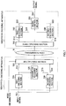
- FIG. 1 is a block diagram showing the main configurations of speech encoding apparatus 100 and speech decoding apparatus 150 according to Embodiment 1 of the present invention.
- speech encoding apparatus 100 hierarchically encodes input signal S11 in accordance with an encoding method according to this embodiment, multiplexes obtained hierarchical encoded information S12 and S14, and transmits multiplexed encoded information (multiplexed information) to speech decoding apparatus 150 via transmission path N.
- speech decoding apparatus 150 demultiplexes the multiplexed information from speech encoding apparatus 100 to encoded information S12 and S14, decodes the encoded information after demultiplexing in accordance with a decoding method according to this embodiment, and outputs output signal S54.
- Speech encoding apparatus 100 is mainly composed of first encoding section 115, parameter decoding section 120, second encoding section 130, and multiplexing section 154, and sections perform the following operations.
- FIG.2 shows a flow of each parameter in speech encoding apparatus 100 according to Embodiment 1.
- First encoding section 115 performs a CELP scheme speech encoding (first encoding) processing on speech signal S11 inputted to speech encoding apparatus 100, and outputs encoded information (first encoded information) S12 representing each parameter obtained based on a generation model of the speech signal to multiplexing section 154. Also, first encoding section 115 also outputs first encoded information S12 to parameter decoding section 120 to perform hierarchical encoding.
- the parameters obtained by the first encoding processing are hereinafter referred to as a first parameter group.
- the first parameter group includes a first quantized LSP (Line Spectral Pairs), a first adaptive excitation lag, a first fixed excitation vector, a first quantized adaptive excitation gain, and a first quantized fixed excitation gain.
- LSP Line Spectral Pairs
- Parameter decoding section 120 performs parameter decoding on first encoded information S12 outputted from first encoding section 115, and generates parameters representing a feature of the generation mode of the speech signal.
- encoded information is not completely decoded, but partially decoded, thereby obtaining the above-described first parameter group. That is, while it is an object of the conventional decoding processing to obtain the original signal before encoding by decoding encoded information, it is an object of the parameter decoding processing to obtain the first parameter group.
- the parameter decoding section 120 demultiplexes first encoded information S12, and obtains a first quantized LSP code (L1), a first adaptive excitation lag code (A1), a first quantized adaptive excitation gain code (G1), and a first fixed excitation vector gain (F1), and obtains a first parameter group S13 from each of the obtained codes.
- This first parameter group S13 is outputted to second encoding section 130.
- Second encoding section 130 obtains a second parameter group by performing second encoding processing which will be described later, using the input signal S11 of speech encoding apparatus 100 and the first parameter group S13 outputted from parameter decoding section 120, and outputs encoded information (second encoded information) S14 representing this second parameter group to multiplexing section 154.
- the second parameter group includes a second quantized LSP, a second adaptive excitation lag, a second fixed excitation vector, a second quantized adaptive excitation gain, and a second quantized fixed excitation gain each corresponding to those of the first parameter group.
- the first encoded information S12 is inputted to multiplexing section 154 from first encoding section 115, and also the second encoded information S14 is inputted from second encoding section 130.
- Multiplexing section 154 selects necessary encoded information in accordance with mode information of the speech signal inputted to speech encoding apparatus 100, multiplexes the selected encoded information and the mode information, and generates the multiplexed encoded information (multiplexed information).
- the mode information is information that indicates encoded information to be multiplexed and transmitted.
- multiplexing section 154 multiplexes the first encoded information S12 and the mode information
- multiplexing section 154 multiplexes the first encoded information S12, the second encoded information S14, and the mode information.
- multiplexing section 154 outputs the multiplexed information after multiplexing to speech decoding apparatus 150 via the transmission path N.
- this embodiment is characterized by the operations of parameter decoding section 120 and second encoding section 130.
- processing of sections will be described in detail in the order of first encoding section 115, parameter decoding section 120, and then second encoding section 130.
- FIG.3 is a block diagram showing an internal configuration of first encoding section 115.
- Preprocessing section 101 performs, on the speech signal S11 inputted to speech encoding apparatus 100, high-pass filter processing of removing DC components and waveform shaping processing and pre-emphasis processing which help to improve the performance of subsequent encoding processing, and outputs the processed signal (Xin) to LSP analyzing section 102 and adder 105.
- LSP analyzing section 102 performs linear prediction analysis using the Xin, converts LPC (Linear Prediction Coefficients) resulting from the analysis into LSP, and outputs the conversion result as a first LPC to LSP quantizing section 103.
- LPC Linear Prediction Coefficients
- LSP quantizing section 103 quantizes the first LSP outputted from LSP analyzing section 102 using quantizing processing which will be described later, and outputs a quantized first LSP (first quantized LSP) to synthesis filter 104. Also, LSP quantizing section 103 outputs a first quantized LSP code (L1) representing the first quantized LSP to multiplexing section 114.
- Synthesis filter 104 performs filer synthesis of a driving excitation outputted from adder 111 using a filter coefficient based on the first quantized LSP, and generates a synthesis signal.
- the synthesis signal is outputted to adder 105.
- Adder 105 reverses the polarity of the synthesis signal, adds this signal to Xin, thereby calculating an error signal, and outputs this calculated error signal to auditory weighting section 112.
- Adaptive excitation codebook 106 has a buffer storing driving excitations which have been previously outputted from adder 111. Also, based on an extraction position specified by a signal outputted from parameter determining section 113, adaptive excitation codebook 106 extracts a set of samples for one frame from the buffer at the extraction position, and outputs the sample set as a first adaptive excitation vector to multiplier 109. Further, adaptive excitation codebook 106 updates the above buffer, each time a driving excitation is inputted from adder 111.
- Quantized gain generating section 107 determines, based on an instruction from parameter determining section 113, a first quantized adaptive excitation gain and a first quantized fixed excitation gain, and outputs the first quantized adaptive excitation gain to multiplier 109 and the first quantized fixed excitation gain to multiplier 110.
- Fixed excitation codebook 108 outputs a vector having a form specified by the instruction from parameter determining section 113 as a first fixed excitation vector to multiplier 110.
- Multiplier 109 multiplies the first quantized adaptive excitation gain outputted from quantized gain generating section 107 by the first adaptive excitation vector outputted from adaptive excitation codebook 106, and outputs the result to adder 111.
- Multiplier 110 multiplies the first quantized fixed excitation gain output from quantized gain generating section 107 by the first fixed excitation vector outputted from fixed excitation codebook 108 and outputs the result to adder 111.
- Adder 111 adds the first adaptive excitation vector multiplied by the gain at multiplier 109 and the first fixed excitation vector multiplied by the gain at multiplier 110, and outputs a driving excitation resulting from the addition to synthesis filter 104 and adaptive excitation codebook 106.
- the driving excitation inputted to adaptive excitation codebook 106 is stored into the buffer.
- Auditory weighting section 112 applies an auditory weight to the error signal outputted from adder 105 and outputs a result as an encoding distortion to parameter determining section 113.
- Parameter determining section 113 selects a first adaptive excitation lag that minimizes the encoding distortion outputted from auditory weighting section 112, and outputs a first adaptive excitation lag code (A1) indicating a selected lag to multiplexing section 114. Also, parameter determining section 113 selects a first fixed excitation vector that minimizes the encoding distortion outputted from auditory weighting section 112, and outputs a first fixed excitation vector code (F1) indicating a selected vector to multiplexing section 114.
- parameter determining section 113 selects a first quantized adaptive excitation gain and a first quantized fixed excitation gain that minimize the encoding distortion outputted from auditory weighting section 112, and outputs a first quantized excitation gain code (G1) indicating selected gains to multiplexing section 114.
- Multiplexing section 114 multiplexes the first quantized LSP code (L1) outputted from LSP quantizing section 103 and the first adaptive excitation lag code (A1), the first fixed excitation vector code (F1), and the first quantized excitation gain code (G1) outputted from parameter determining section 113, and outputs the result as the first encoded information S12.
- FIG.4 is a block diagram showing an internal configuration of parameter decoding section 120.
- Demultiplexing section 121 demultiplexes the first encoded information S12 outputted from first encoding section 115 into individual codes (L1, A1, G1, and F1), and output codes to each component .
- the first quantized LSP code (L1) demultiplexed from the first encoded information S12 is outputted to LSP decoding section 122
- the first adaptive excitation lag code (A1) demultiplexed as well is outputted to adaptive excitation codebook 123
- the first quantized excitation gain code (G1) demultiplexed as well is outputted to quantized gain generating section 124
- the first fixed excitation vector code (F1) demultiplexed as well is outputted to fixed excitation codebook 125.
- LSP decoding section 122 decodes the first quantized LSP code (L1) outputted from demultiplexing section 121 to a first quantized LSP, and outputs the decoded first quantized LSP to second encoding section 130.
- Adaptive excitation codebook 123 decodes an extraction position specified by the first adaptive excitation lag code (A1) as a first adaptive excitation lag. Then, adaptive excitation codebook 123 outputs the obtained first adaptive excitation lag to second encoding section 130.
- Quantized gain generating section 124 decodes the first quantized adaptive excitation gain and the first quantized fixed excitation gain specified by the first quantized excitation gain code (G1) outputted from demultiplexing section 121. Then, quantized gain generating section 124 outputs the obtained first quantized adaptive excitation gain to second encoding section 130, and also the first quantized fixed excitation gain to second encoding section 130.
- Fixed excitation codebook 125 generates a first fixed excitation vector specified by the first fixed excitation vector code (F1) outputtedfrom demultiplexing section 121, and outputs the vector to second encoding section 130.
- first quantized LSP first adaptive excitation lag
- first fixed excitation vector first fixed excitation vector
- first quantized adaptive excitation gain first quantized fixed excitation gain
- FIG.5 is a block diagram showing an internal configuration of second encoding section 130.
- Preprocessing section 131 performs, on the speech signal S11 inputted to speech encoding apparatus 100, high-pass filter processing of removing DC components and waveform shaping processing and pre-emphasis processing which help to improve the performance of subsequent encoding processing, and outputs the processed signal (Xin) to LSP analyzing section 132 and adder 135.
- LSP analyzing section 132 performs linear prediction analysis using the Xin, converts LPC (Linear Prediction Coefficients) resulting from the analysis into LSP (Line Spectral Pairs), and outputs the conversion result as a second LSP to LSP quantizing section 133.
- LPC Linear Prediction Coefficients
- LSP quantizing section 133 reverses the polarity of the first quantized LSP outputted from parameter decoding section 120, adds the first quantized LSP after polarity reversion to the second LSP outputted from LSP analyzing section 132 and thereby calculating a residual LSP.
- LSP quantizing section 133 quantizes the calculated residual LSP using quantizing processing which will be described later, adds the quantized residual LSP (quantized residual LSP) and the first quantized LSP outputted from parameter decoding section 120, and thereby calculating a second quantized LSP. This second quantized LSP is outputted to synthesis filter 134, while the second quantized LSP code (L2) representing the quantized residual LSP is outputted to multiplexing section 144.
- Synthesis filter 134 performs filter synthesis of a driving excitation, outputted from adder 141, by a filter coefficient based on the second quantized LSP, and thereby generates a synthesis signal.
- the synthesis signal is outputted to adder 135.
- Adder 135 reverses the polarity of the synthesis signal, adds this signal to Xin, thereby calculating an error signal, and outputs this calculated error signal to auditory weighting section 142.
- Adaptive excitation codebook 136 has a buffer storing driving excitations which have been previously outputted from adder 141. Also, based on an extraction position specified by the first adaptive excitation lag and a signal outputted from parameter determining section 143, adaptive excitation codebook 136 extracts a set of samples for one frame from the buffer at the extraction position, and outputs the sample set as a second adaptive excitation vector to multiplier 139. Further, adaptive excitation codebook 136 updates the above buffer, each time a driving excitation is inputted from adder 141.
- Quantized gain generating section 137 obtains, based on an instruction from parameter determining section 143, a second quantized adaptive excitation gain and a second quantized fixed excitation gain using the first quantized adaptive excitation gain and the first quantized fixed excitation gain outputted from parameter decoding section 120.
- the second quantized adaptive excitation gain is outputted to multiplier 139, and the second quantized fixed excitation gain is outputted to multiplier 140.
- Fixed excitation codebook 138 obtains a second fixed excitation vector by adding a vector having a form specified by the indication from parameter determining section 143 and the first fixed excitation vector outputted from parameter decoding section 120, and outputs the result to multiplier 140.
- Multiplier 139 multiplies the second adaptive excitation vector outputted from adaptive excitation codebook 136 by the second quantized adaptive excitation gain outputted from quantized gain generating section 137, and outputs the result to adder 141.
- Multiplier 140 multiplies the second fixed excitation vector outputted from fixed excitation codebook 138 by the second quantized fixed excitation gain outputted from quantized gain generating section 137, and outputs the result to adder 141.
- Adder 141 adds the second adaptive excitation vector multiplied by the gain at multiplier 139 and the second fixed excitation vector multiplied by the gain at multiplier 140, and outputs a driving excitation resulting from the addition to synthesis filter 134 and adaptive excitation codebook 136.
- the driving excitation inputted to adaptive excitation codebook 136 is stored into the buffer.
- Auditory weighting section 142 applies an auditory weighting to the error signal outputted from adder 135, and outputs a result as encoding distortion to parameter determining section 143.
- Parameter determining section 143 selects a second adaptive excitation lag that minimizes the encoding distortion output from auditory weighting section 142, and outputs a second adaptive excitation lag code (A2) indicating the a selected lag to multiplexing section 144. Also, parameter determining section 143 selects a second fixed excitation vector that minimizes the encoding distortion outputted from auditory weighting section 142 using the first adaptive excitation lag outputted from parameter decoding section 120, and outputs a second fixed excitation vector code (F2) indicating a selected vector to multiplexing section 144.
- parameter determining section 143 selects a second quantized adaptive excitation gain and a second quantized fixed excitation gain that minimizes the encoding distortion outputted from auditory weighting section 142, and outputs a second quantized excitation gain code (G2) indicating a selected gain to multiplexing section 144.
- G2 second quantized excitation gain code
- Multiplexing section 144 multiplexes the second quantized LSP code (L2) outputted from LSP quantizing section 133 and the second adaptive excitation lag code (A2), the second fixed excitation vector code (F2), and the second quantized excitation gain code (G2) outputted from parameter determining section 143, outputs the result as the second encoded information S14.
- LSP quantizing section 133 shown in FIG. 5 determines a second quantized LSP.
- L2 the number of bits assigned to the second quantized LSP code (L2) is "8" and the residual LSP is vector-quantized.
- LSP quantizing section 133 is provided with second LSP codebook in which 256 variants of second LSP code vectors [lsp res (L2') (i)] created in advance are stored.
- L2' is an index attached to the second LDP code vector, and takes any value of 0 to 255.
- lsp res (L2') (i) is an N-dimensional vector, and i takes a value from 0 to N-1.
- a second LSP [ ⁇ 2 (i)] is inputted to LSP quantizing section 133 from LSP analyzing section 132.
- ⁇ 2 (i) is an N-dimensional vector, and i takes a value from 0 to N-1.
- a first quantized LSP [lsp 1 (L1'min) (i)] is also inputted to LSP quantizing section 133 from parameter decoding section 120.
- lsp 1 (L1'min) (i) is an N-dimensional vector, and i takes a value from 0 to N-1.
- LSP quantizing section 133 obtains a residual LSP [res(i)] by the following (Equation 1).
- LSP quantizing section 133 obtains squared error er 2 between the residual LSP [res(i)] and the second LSP code vector [lsp res (L2') (i)] by the following (Equation 2) .
- LSP quantizing section 133 obtains a squared error er 2 for all L2' and determines a value of L2' (L2'min) that minimizes the squared error er 2 .
- the determined L2'min is outputted to multiplexing section 144 as a second quantized LSP code (L2).
- LSP quantizing section 133 obtains a second quantized LSP [lsp 2 (i)] by the following (Equation 3).
- LSP quantizing section 133 outputs this second quantized LSP [lsp 2 (i)] to synthesis filter 134.
- [lsp 2 (i)] obtained by LSP quantizing section 133 is the second quantized LSP
- lsp res (L2'min) (i) that minimizes the squared error er 2 is a quantized residual LSP.
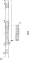
- FIG. 6 outlines processing of determining a second adaptive excitation lag by parameter determining section 143 shown in FIG. 5 .
- a buffer B2 is a buffer provided by adaptive excitation codebook 136
- a position P2 is an extraction position of the second adaptive excitation vector
- a vector V2 is extracted second adaptive excitation vector.
- t represents a first adaptive excitation lag
- values 41 and 296 correspond to a lower limit and an upper limit of the range in which parameter determining section 143 searches for the first adaptive excitation lag.
- t-16 and t+15 correspond to a lower limit and an upper limit of the range in which the extraction position of the second adaptive excitation vector is shifted.
- the range in which the extraction position P2 is shifted can be arbitrarily set.
- Parameter determining section 143 sets the range in which the extraction position P2 is shifted at t-16 to t+15 with reference to the first adaptive excitation lag t inputted from parameter decoding section 120. Next, parameter determining section 143 shifts the extraction position P2 within the above range and sequentially specifies the extraction position P2 to adaptive excitation codebook 136.
- Adaptive excitation codebook 136 extracts the second adaptive excitation vector V2 for the length of the frame from the extraction position P2 specified by parameter determining section 143, and outputs the extracted second adaptive excitation vector V2 to multiplier 139.
- Parameter determining section 143 obtains an encoding distortion outputted from auditory weighting section 142 for all second adaptive excitation vectors V2 extracted from all extraction positions P2, and determines an extraction position P2 that minimizes this encoding distortion.
- the buffer extraction position P2 obtained by the parameter determining section 143 is the second adaptive excitation lag.
- Parameter determining section 143 encodes a difference (in the example of FIG. 6 , -16 to +15) between the first adaptive excitation lag and the second adaptive excitation lag, and outputs the code obtained through encoding to multiplexing section 144 as the second adaptive excitation lag code (A2).
- second decoding section 180 adds the first adaptive excitation lag (t) obtained through the first adaptive excitation lag code and the difference from the second adaptive excitation lag code (-16 to +15), thereby decoding the second adaptive excitation lag (t-16 to t+15).
- parameter determining section 143 receives the first adaptive excitation lag t from parameter decoding section 120, and searches for a range around this t in search for the second adaptive excitation lag, thereby making it possible to quickly find an optimum second adaptive excitation lag.
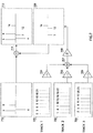
- FIG.7 outlines processing of determining a second fixed excitation vector by the above parameter determining section 143. This figure indicates the process of generating a second fixed excitation vector from algebraic fixed excitation codebook 138.
- Track 1, track 2, and track 3 each generate one unit pulse (701, 702, and 703) with an amplitude value of 1 (solid lines in the figure) .
- Each track has different positions where a unit pulse can be generated.
- the tracks are configured such that track 1 raises a unit pulse at any of eight positions ⁇ 0, 3, 6, 9, 12, 15, 18, 21 ⁇ , track 2 raises a unit pulse at any of eight positions ⁇ 1, 4, 7, 10, 13, 16, 19, 22 ⁇ , and track 3 raises a unit pulse at any of eight positions ⁇ 2, 5, 8, 11, 14, 17, 20, 23 ⁇ .
- Multiplier 704 applies polarity to the unit pulse generated in track 1.
- Multiplier 705 applies polarity to the unit pulse generated in track 2.
- Multiplier 706 applies polarity to the unit pulse generated in track 3.
- Adder 707 adds the generated three unit pulses together.
- Multiplier 708 multiplies the added three unit pulses by a predetermined constant ⁇ .
- the constant ⁇ is a constant for changing the magnitude of the pulse, and it has been experimentally known that an excellent performance can be obtained when the constant ⁇ is set at a value in the order of 0 to 1. Also, the value of the constant ⁇ may be set so as to obtain a performance suitable according to the speech encoding apparatus.
- Adder 711 adds residual fixed excitation vector 709 composed of three pulses and a first fixed excitation vector 710 together, and obtains second fixed excitation vector 712.
- residual fixed excitation vector 709 is multiplied by the constant ⁇ in a range from 0 to 1 and is then added to first fixed excitation vector 710, and as a result, weighting addition with the first fixed excitation vector 710 being weighted is applied.
- unit pulse has eight patterns of positions and two patterns of positions, positive and negative, and three bits for position information and one bit for polarity information are used to represent each unit pulse. Therefore, the fixed excitation codebook has 12 bits in total.
- parameter determining section 143 sequentially indicates the generation position and polarity to fixed excitation codebook 138.
- Fixed excitation codebook 138 configures residual fixed excitation vector 709 using the generation position and polarity indicated by parameter determining section 143, adds the configured residual fixed excitation vector 709 and first fixed excitation vector 710 outputted from parameter decoding section 120 together, and outputs second fixed excitation vector 712 resulting from the addition to multiplier 140.
- Parameter determining section 143 obtains an encoding distortion outputted from auditory weighting section 142 for the second fixed excitation vector with respect to all combinations of the generation position and polarity, and determines a combination of the generation position and polarity that minimizes the encoding distortion. Next, parameter determining section 143 outputs the second fixed excitation vector code (F2) representing the determined combination of the generation position and the polarity to multiplexing section 144.
- F2 the second fixed excitation vector code
- the above parameter determining section 143 carries out an instruction to quantized gain generating section 137, and determines a second quantized adaptive excitation gain and a second quantized fixed excitation gain.
- a case will be described as an example where 8 bits are assigned to the second quantized excitation gain code (G2).
- Quantized gain generating section 137 is provided with a residual excitation gain codebook in which 256 variants of residual excitation gain code vectors [gain 2 (K2') (i)] created in advance are stored.
- K2' is an index attached to the residual excitation gain code vector, and takes any value of 0 to 255.
- gain 2 (K2') (i) is a two-dimensional vector, and i takes a value from 0 to 1.
- Parameter determining section 143 indicates a value of K2' from 0 to 255 to quantized gain generating section 137.
- Quantized gain generating section 137 selects a residual excitation gain code vector [gain 2 (K2') (i)] from the residual excitation gain codebook using K2' indicated by parameter determining section 143, obtains a second quantized adaptive excitation gain [gain q (0)] from the following (Equation 4), and outputs the obtained gain q (0) to multiplier 139.
- gain q 0 gain 1 K 1 ′ min 0 + gain 2 K 2 ′ 0
- quantized gain generating section 137 obtains a second quantized fixed excitation gain [gain q (1)] from the following (Equation 5), and outputs the obtained gain q (1) to multiplier 140.
- gain q 1 gain 1 K 1 ′ min 1 + gain 2 K 2 ′ 1
- gain 1 (k1'min) (0) represents a first quantized adaptive excitation gain
- gain 1 (k1'min) (1) represents a first quantized fixed excitation gain, each being outputted from parameter decoding section 120.
- gain q (0) obtained by quantized gain generating section 137 represents a second quantized adaptive excitation gain
- gain q (1) is a second quantized fixed excitation gain
- Parameter determining section 143 obtains an encoding distortion outputted from auditory weighting section 142 for all K2', and determines a value of K2' (K2'min) that minimizes the encoding distortion. Next, parameter determining section 143 outputs the determined K2'min to multiplexing section 144 as a second quantized excitation gain code (G2).
- CELP scheme speech encoding suitable for encoding a speech signal can be effectively applied, thereby obtaining decoded signal with good quality.
- second encoding section 130 encodes the input signal using the first parameter group and generates a second parameter group
- the decoding apparatus side can generate a second decoded signal using two parameter groups (the first parameter group and the second parameter group).
- parameter decoding section 120 partially decodes the first encoded information S12 inputted from first encoding section 115 and outputs each obtained parameter to second encoding section 130 corresponding to an upper layer of first encoding section 115, and second encoding section 130 performs second encoding using each of these parameters and the input signal of speech encoding apparatus 100.
- second encoding section 130 encodes, by CELP scheme speech encoding, a difference between an LSP obtained by a linear prediction analysis on the speech signal that is the input of speech encoding apparatus 100 and a quantized LSP generated by parameter decoding section 120. That is, second encoding section 130 takes a difference at the stage of the LSP parameter, and performs CELP scheme speech encoding on this difference, thereby achieving CELP scheme speech encoding that does not take a residual signal as an input.
- the second encoded information S14 outputted from (second encoding section 130 of) speech encoding apparatus 100 is a totally new signal not generated from any conventional speech encoding apparatus.
- the following describes processing of determining a first quantized LSP by LSP quantizing section 103 in first encoding section 115.
- LSP quantizing section 103 is provided with a first LSP codebook in which 256 variants of first LSP code vectors [lsp 1 (L1') (i)] created in advance are stored.
- L1' is an index attached to the first LDP code vector, and takes any value of 0 to 255.
- lsp 1 (L1') (i) is an N-dimensional vector, and i takes a value from 0 to N-1.
- a first LSP [ ⁇ 1 (i)] is inputted to LSP quantizing section 103 from LSP analyzing section 102.
- ⁇ 1 (i) is an N-dimensional vector, and i takes a value from 0 to N-1.
- LSP quantizing section 103 obtains a squared error er 1 between the first LSP [ ⁇ 1 (i)] and the first LSP code vector [lsp 1 (L1'min) (i)] from the following (Equation 6).
- LSP quantizing section 103 obtains a squared error er 1 for all L1' to determine a value of L1' (L1'min) that minimizes the squared error er 1 . Then, LSP quantizing section 103 outputs this determined L1'min to multiplexing section 114 as a first quantized LSP code (L1), and also outputs lsp 1 (L1'min) (i) to synthesis filter 104 as a first quantized LSP.
- lsp 1 (L1'min) (i) obtained by LSP quantizing section 103 is the first quantized LSP.
- FIG.8 outlines processing of determining a first adaptive excitation lag by parameter determining section 113 in first encoding section 115.
- a buffer B1 is a buffer provided by adaptive excitation codebook 106
- a position P1 is an extraction position of the first adaptive excitation vector
- a vector V1 is an extracted first adaptive excitation vector.
- values 41 and 296 correspond to lower and upper limits of the range of shifting extraction position P1.
- the range of shifting the extraction position P1 can be arbitrarily set.
- Parameter determining section 113 shifts the extraction position P1 within the set range, and sequentially indicates the extraction position P1 to adaptive excitation codebook 106.
- Adaptive excitation "codebook 106 extracts the first adaptive excitation vector V1 with a length of the frame by the extraction position P1 indicated from parameter determining section 113, and outputs the extracted first adaptive excitation vector to multiplier 109.
- Parameter determining section 113 obtains the encoding distortion outputted from auditory weighting section 112 for all first adaptive excitation vectors V1 extracted from all extraction positions P1, and determines an extraction position P1 that minimizes the encoding distortion. Extraction position P1 from buffer obtained by parameter determining section 113 is the first adaptive excitation lag. Parameter determining section 113 outputs the first adaptive excitation lag code (A1) indicating the first adaptive excitation lag to multiplexing section 114.
- A1 the first adaptive excitation lag code
- FIG.9 outlines processing of determining a first fixed excitation vector by parameter determining section 113 in first encoding section 115. This figure indicates the process of generating a first fixed excitation vector from an algebraic fixed excitation codebook.
- Track 1, track 2, and track 3 each generate one unit pulse (having an amplitude value of 1). Also, multiplier 404, multiplier 405, and multiplier 406 assign polarity to the unit pulse generated by tracks 1 to 3. Adder 407 adds the generated three unit pulses together, and vector 408 is a first fixed excitation vector consisting of three unit pulses.
- Each track has different position where a unit pulse can be generated, and in this figure, the tracks are configured such that track 1 raises a unit pulse at any of eight positions ⁇ 0, 3, 6, 9, 12, 15, 18, 21 ⁇ , track 2 raises a unit pulse at any of eight positions ⁇ 1, 4, 7, 10, 13, 16, 19, 22 ⁇ , and track 3 raises a unit pulse at any of eight positions ⁇ 2, 5, 8, 11, 14, 17, 20, 23 ⁇ .
- Polarity is assigned to the generated unit pulse in each track by multipliers 404 to 406, respectively, the three unit pulses are added at adder 407, and first fixed excitation vector 408 resulting from the addition is formed.
- unit pulse has eight patterns of positions and two patterns of position, positive and negative, and three bits for position information and one bit for polarity information are used to represent each unit pulse. Therefore, the fixed excitation codebook has 12 bits in total.
- Parameter determining section 113 shifts the generation position of the three unit pulses and polarity, and sequentially indicates the generation position and polarity to fixed excitation codebook 108.
- Fixed excitation codebook 108 configures first fixed excitation vector 408 using the generation position and polarity indicated by parameter determining section 113, and outputs the configured first fixed excitation vector 408 to multiplier 110.
- Parameter determining section 113 obtains an encoding distortion outputted from auditory weighting section 112 for all combinations of the generation positions and polarity, and determines a combination of the generation positions and polarity that minimizes the encoding distortion. Next, parameter determining section 113 outputs the first fixed excitation vector code (F1) indicating the combination of the generation positions and polarity that minimizes the encoding distortion to multiplexing section 114.
- F1 first fixed excitation vector code
- parameter determining section 113 in first encoding section 115 indicates quantized gain generating section 107 and determines a first quantized adaptive excitation gain and a first quantized fixed excitation gain.
- description will be made with an example where 8 bits are assigned to the first quantized excitation gain code (G1).
- Quantized gain generating section 107 is provided with a first excitation gain codebook in which 256 variants of first excitation gain code vectors [gain 1 (K1') (i)] created in advance are stored.
- K1' is an index attached to the first excitation gain code vector, and takes any value of 0 to 255.
- gain 1 (K1') (i) is a two-dimensional vector, and i takes a value from 0 to 1.
- Parameter determining section 113 sequentially indicates a value of K1' from 0 to 255 to quantized gain generating section 107.
- Quantized gain generating section 107 selects a first excitation gain code vector [gain 1 (K1') (i)] from the first excitation gain codebook using K1' indicated by parameter determining section 113, outputs gain 1 (K1') (0) to multiplier 109 as a first quantized adaptive excitation gain and gain 1 (K1') (1) to multiplier 110 as a first quantized fixed excitation gain.
- gain 1 (K1') (0) obtained by quantized gain generating section 107 represents the first quantized adaptive excitation gain
- gain 1 (K1') (1) represents the first quantized fixed excitation gain
- Parameter determining section 113 obtains an encoding distortion outputted from auditory weighting section 112 for all K1' and determines a value of K1' (K1'min) that minimizes the encoding distortion. Next, parameter determining section 113 outputs K1'min to multiplexing section 114 as a first quantized excitation gain code (G1).
- speech decoding apparatus 150 will be described where the encoded information S12 and S14 transmitted from the above-configured speech encoding apparatus 100 are decoded.
- first decoding section 160 the main configurations of speech decoding apparatus 150 are provided by first decoding section 160, second decoding section 180, signal control section 195, and demultiplexing section 155. Sections of speech decoding apparatus 150 perform the following operations.
- Demultiplexing section 155 demultiplexes the mode information and the encoded information multiplexed and outputted from speech encoding apparatus 100, and outputs the first encoded information S12 to first decoding section 160 when the mode information is "0" and "1", the second encoded information S14 to second decoding section 180 when the mode information is "1". Also, demultiplexing section 155 outputs the mode information to signal control section 195.
- First decoding section 160 decodes the first encoded information S12 outputted from demultiplexing section 155 by using a CELP scheme speech decoding method (first decoding), and outputs a first decoded signal S52 obtained by decoding to signal control section 195. Also, first decoding section 160 outputs the first parameter group S51 obtained in the decoding to second decoding section 180.
- first decoding decodes the first encoded information S12 outputted from demultiplexing section 155 by using a CELP scheme speech decoding method (first decoding), and outputs a first decoded signal S52 obtained by decoding to signal control section 195. Also, first decoding section 160 outputs the first parameter group S51 obtained in the decoding to second decoding section 180.
- Second decoding section 180 performs a second decoding process using the first parameter group S51 outputted from first decoding section 160, which will be described later, performs decoding on the second encoded information S14 outputted from demultiplexing section 155, generates a second decoded signal S53 and outputs the result to signal control section 195
- Signal control section 195 inputs the first decoded signal S52 outputted from first decoding section 160 and the second decoded signal S53 outputted from second decoding section 180, and outputs a decoded signal in accordance with the mode information outputted from demultiplexing section 155. Specifically, firstdecoded signal S52 is outputted as an output signal when the mode information is "0" and the second decoded signal S53 is outputted as an output signal when the mode information is "1".
- FIG.10 is a block diagram showing an internal configuration of first decoding section 160.
- Demultiplexing section 161 demultiplexes the first encoded information S12 inputted to first decoding section 160 into individual codes (L1, A1, G1, and F1), and outputs codes to each component. Specifically, the first quantized LSP code (L1) demultiplexed from the first encoded information S12 is outputted to LSP decoding section 162, the first adaptive excitation lag code (A1) demultiplexed as well is outputted to adaptive excitation codebook 165, the first quantized excitation gain code (G1) demultiplexed as well is outputted to quantized gain generating section 166, and first fixed excitation vector code (F1) demultiplexed as well is outputted to fixed excitation codebook 167.
- LSP decoding section 162 decodes the first quantized LSP code (L1) outputted from demultiplexing section 161 to a first quantized LSP, and outputs the decoded first quantized LSP to synthesis filter 163 and second encoding section 180.
- Adaptive excitation codebook 165 extracts a set of samples for one frame from the buffer at an extraction position specified by the first adaptive excitation lag code (A1) outputted from demultiplexing section 161, and outputs the extracted vector to multiplier 168 as a first adaptive excitation vector. Also, adaptive excitation codebook 165 outputs the extraction position specified by the first adaptive excitation lag code (A1) to second decoding section 180 as a first adaptive excitation lag.
- Quantized gain generating section 166 decodes the first quantized adaptive excitation gain and the first quantized fixed excitation gain specified by the first quantized excitation gain code (G1) outputted from demultiplexing section 161. Then, quantized gain generating section 166 outputs the obtained first quantized adaptive excitation gain to multiplier 168 and second decoding section 180, and also the first quantized fixed excitation gain to multiplier 169 and second decoding section 180.
- Fixed excitation codebook 167 generates a first fixed excitation vector specified by the first fixed excitation vector code (F1) outputted from demultiplexing section 161, and outputs the vector to multiplier 169 and second decoding section 180.
- Multiplier 168 multiplies the first adaptive excitation vector by the first quantized adaptive excitation gain, and outputs the result to adder 170.
- Multiplier 169 multiplies the first fixed excitation vector by the first quantized fixed excitation gain, and outputs the result to adder 170.
- Adder 170 adds the first adaptive excitation vector and the first fixed excitation vector after gain multiplication outputted from multipliers 168 and 169, generates a driving excitation, and outputs the generated driving excitation to synthesis filter 163 and adaptive excitation codebook 165.
- Synthesis filter 163 performs filer synthesis using the driving excitation outputted from adder 170 and the filter coefficient decoded by LSP decoding section 162, and outputs a synthesis signal to postprocessing section 164.
- Postprocessing section 164 processes the synthesis signal outputted from synthesis filter 163 by performing processing for improving a subjective speech quality, such as formant emphasizing or pitch emphasizing, and by performing processing for improving a subjective stationary noise quality , and outputs the processed result as a first decoded signal S52.
- a subjective speech quality such as formant emphasizing or pitch emphasizing
- the reproduced parameters are outputted to second decoding section 180 as the first parameter group S51.
- FIG.11 is a block diagram showing an internal configuration of second decoding section 180.
- Demultiplexing section 181 demultiplexes the second encoded information S14 inputted to second decoding section 180 into individual codes (L2, A2, G2, and F2), and outputs codes to each component. Specifically, the second quantized LSP code (L2) demultiplexed from the second encoded information S14 is outputted to LSP decoding section 182, the second adaptive excitation lag code (A2) demultiplexed as well is outputted to adaptive excitation codebook 185, the second quantized excitation gain code (G2) demultiplexed as well is outputted to quantized gain generating section 186, and the second fixed excitation vector code (F2) demultiplexed as well is outputted to fixed excitation codebook 187.
- L2 the second quantized LSP code
- A2 adaptive excitation lag code
- G2 quantized excitation gain code
- F2 fixed excitation vector code
- LSP decoding section 182 decodes the second quantized LSP code (L2) outputted from demultiplexing section 181 to a quantized residual LSP, adds the quantized residual LSP and the first quantized LSP outputted from first decoding section 160, and outputs a second quantized LSP resulting from the addition to synthesis filter 183.
- Adaptive excitation codebook 185 extracts a set of samples for one frame from the buffer at an extraction position specified by the first adaptive excitation lag outputted from first decoding section 160 and the second adaptive excitation lag code (A1) outputted from demultiplexing section 181, and outputs the extracted vector to multiplier 188 as a second adaptive excitation vector.
- Quantized gain generating section 186 obtains a second quantized adaptive excitation gain and a second quantized fixed excitation gain using the first quantized adaptive excitation gain and the first quantized fixed excitation gain outputted from first decoding section 160 and the second quantized excitation gain code (G2) outputted from demultiplexing section 181, and outputs the second quantized adaptive excitation gain to multiplier 188 and the second quantized fixed excitation gain to multiplier 189.
- Fixed excitation codebook 187 generates a residual fixed excitation vector specified by the second fixed excitation vector code (F2) outputted from demultiplexing section 181, adds the generated residual fixed excitation vector and the first fixed excitation vector outputted from first decoding section 160, and outputs a second fixed excitation vector resulted from the addition to multiplier 189.
- Multiplier 188 multiplies the second adaptive excitation vector by the second quantized adaptive excitation gain, and outputs the result to adder 190.
- Multiplier 189 multiplies the second fixed excitation vector by the second quantized fixed excitation gain, and outputs the result to adder 190.
- Adder 190 generates a driving excitation by adding the second adaptive excitation vector gain multiplied by multiplier 188 and the second fixed excitation vector gain multiplied by multiplier 189, and outputs the generated driving excitation to synthesis filter 183 and adaptive excitation codebook 185.
- Synthesis filter 183 performs filer synthesis using the driving excitation outputted from adder 190 and a filter coefficient decoded by LSP decoding section 182, and outputs a synthesis signal to postprocessing section 184.
- Postprocessing section 184 processes the synthesis signal outputted from synthesis filter 183 by performing processing for improving a subjective speech quality, such as formant emphasizing or pitch emphasizing, and by performing for improving a subjective stationary noise quality, and outputs the processed signal as a second decoded signal S53.
- a subjective speech quality such as formant emphasizing or pitch emphasizing
- the first decoded signal is generated from the first parameter group obtained by decoding the first encoded information
- the second decoded signal is generated from the second parameter group obtained by decoding the second encoded information and the first parameter group, and thereby these signals can be obtained as output signals.
- this signal can be obtained as an output signal. That is, by adopting a configuration capable of obtaining an output signal using all or part of the encoded information, a function capable of decoding speech/sound even from part of encoded information (hierarchical encoding) can be implemented.
- first decoding section 160 performs decoding on the first encoded information S12 and also outputs the first parameter group S51 obtained in this decoding to second decoding section 180, and second decoding section 180 decode the second encoded information S14 using this first parameter group S51.
- the speech decoding apparatus according to this embodiment can decode a signal hierarchically encoded by the speech encoding apparatus according to the present invention.
- parameter decoding section 120 demultiplexes individual codes (L1, A1, G1, and F1) from the first encoded information S12 outputted from first encoding section 115, but the multiplexing and demultiplexing procedure may be omitted by directly inputting each of the codes from first encoding section 115 to parameter decoding section 120.
- the first fixed excitation vector generated by fixed excitation codebook 108 and the second fixed excitation vector generated by fixed excitation codebook 138 are formed by pulses, but vectors may be formed by spread pulses.
- FIG.12A is a block diagram showing a configuration of speech/sound transmitting apparatus according to Embodiment 2 having incorporated therein speech encoding apparatus 100 described in Embodiment 1.
- Speech/sound signal 1001 is converted by input apparatus 1002 into an electrical signal, and outputted to A/D converting apparatus 1003.
- A/D converting apparatus 1003 converts a (analog) signal outputted from input apparatus 1002 into a digital signal, and outputs the digital signal to speech/sound encoding apparatus 1004.
- Speech/sound encoding apparatus 1004 incorporates speech encoding apparatus 100 shown in FIG.1 , encodes the digital speech/sound signal outputted from A/D converting apparatus 1003 and outputs the encoded information to RF modulating apparatus 1005.
- RF modulating apparatus 1005 converts the encoded information outputted from speech/sound encoding apparatus 1004 to a signal to transmit on a propagation medium, such as a radio wave, and outputs the signal to transmission antenna 1006.
- Transmission antenna 1006 transmits the output signal outputted from RF modulating apparatus 1005 as a radio wave (RF signal).
- RF signal 107 in the figure represents a radio wave (RF signal) sent from transmission antenna 1006.
- FIG.12B is a block diagram showing the configuration of a speech/sound receiving apparatus according to Embodiment 2 having incorporated therein speech decoding apparatus 150 described in Embodiment 1.
- RF signal 1008 is received by reception antenna 1009 and output to RF demodulating apparatus 1010.
- RF signal 1008 represents the radio wave received by reception antenna 1009, and is identical to RF signal 1007, unless the signal is attenuated or noise is superimposed on it in a propagation path.
- RF demodulating apparatus 1010 demodulates the RF signal outputted from reception antenna 1009 into encode information, and outputs the encoded information to speech/sound decoding apparatus 1011.
- Speech/sound decoding apparatus 1011 incorporates speech decoding apparatus 150 shown in FIG.1 , decodes the speech/sound signal from the encoded information outputted from RF demodulating apparatus 1010, and outputs the encoded information to D/A converting apparatus 1012.
- D/A converting apparatus 1012 converts the digital speech/sound signal outputted from speech/sound decoding apparatus 1011 into an analog electrical signal, and outputs the signal to output apparatus 1013.
- Output apparatus 1013 converts the electrical signal into air vibration, and outputs it as acoustic waves that can be heard by human ears.
- reference numeral 1014 indicates outputted acoustic wave.
- the speech encoding apparatus and speech decoding apparatus can be implemented in the speech/sound signal transmitting apparatus and the speech/sound signal receiving apparatus.
- Embodiment 1 a case has been described as an example in which the speech encoding method according to the present invention, that is, processing mainly performed by parameter decoding section 120 and second encoding section 130, is performed at the second layer.
- the speech encoding method according to the present invention can be performed not only at the second layer but also at another enhancement layer.
- the speech encoding method of the present invention may be performed at both the second layer and the third layer. Such embodiment will be described below in detail.
- FIG.13 is a block diagram showing the main configurations of speech encoding apparatus 300 and speech decoding apparatus 350 according to Embodiment 3.
- these speech encoding apparatus 300 and speech decoding apparatus 350 have a basic configuration similar to that of speech encoding apparatus 100 and speech decoding apparatus 150 shown in Embodiment 1.
- the same components are assigned the same reference numerals and the description thereof will be omitted.
- speech encoding apparatus 300 will be described.
- the speech encoding apparatus 300 is further provided with second parameter decoding section 310 and third encoding section 320 in addition to the configuration of speech encoding apparatus 100 shown in Embodiment 1.
- First parameter decoding section 120 outputs the first parameter group S13 obtained by parameter decoding to second encoding section 130 and third encoding section 320.
- Second encoding section 130 obtains a second parameter group by a second encoding process, and outputs second encoded information S14 representing this second parameter group to multiplexing section 154 and second parameter decoding section 310.
- Second parameter decoding section 310 performs parameter decoding, which is similar to that of first parameter decoding section 120, on the second encoded information S14 outputted from second encoding section 130. Specifically, second parameter decoding section 310 demultiplexes the second decoded information S14, and obtains a second quantized LSP code (L2), a second adaptive excitation lag code (A2), a second quantized excitation gain code (G2), and a second fixed excitation vector code (F2), and obtains a second parameter group S21 from each of the obtained codes . The second parameter group S21 is outputted to third encoding section 320.
- L2 second quantized LSP code
- A2 adaptive excitation lag code
- G2 second quantized excitation gain code
- F2 second fixed excitation vector code
- Third encoding section 320 performs a third encoding process using the input signal S11 of speech encoding apparatus 300, the first parameter group S13 outputted from first parameter decoding section 120, and the second parameter group S21 outputted from second parameter decoding section 310, thereby obtaining a third parameter group, and outputs encoded information (third encoded information) S22 representing this third parameter group to multiplexing section 154.
- the third parameter group is composed of, correspondingly to the first and second parameter groups, a third quantized LSP, a third adaptive excitation lag, a third fixed excitation vector, a third quantized adaptive excitation gain, and a third quantized fixed excitation gain.
- the first encoded information is inputted to multiplexing section 154 from first encoding section 115, the second encoded information is inputted from second encoding section 130, and the third encoded information is inputted from third encoding section 320.
- multiplexing section 154 multiplexes each piece of encoded information and mode information, and generates multiplexed encoded information (multiplexed information). For example, when the mode information is "0", multiplexing section 154 multiplexes the first encoded information and the mode information. When the mode information is "1", multiplexing section 154 multiplexes the first encoded information, the second encoded information, and the mode information.
- multiplexing section 154 multiplexes the first encoded information, the second encoded information, the third encoded information, and the mode information. Next, multiplexing section 154 outputs the multiplexed information after multiplexing to speech decoding apparatus 350 via the transmission path N.
- speech decoding apparatus 350 will be described.
- the speech decoding apparatus 350 is further provided with third decoding section 360 in addition to the configuration of speech decoding apparatus 150 shown in Embodiment 1.
- Demultiplexing section 155 demultiplexes the mode information and the encoded information outputted from speech encoding apparatus 300 after multiplexing, and outputs the first encoded information S12 to first decoding section 160 when the mode information is "0", “1", or “2", the second encoded information S14 to second decoding section 180 when the mode information is "1" or "2”, and the third encoded information S22 to third decoding section 360 when the mode information indicates "2".
- First decoding section 160 outputs the first parameter group S51 obtained in the first decoding to second decoding section 180 and third decoding section 360.
- Second decoding section 180 outputs the second parameter group S71 obtained in the second decoding to third decoding section 360.
- Third decoding section 360 performs a third decoding process on the third encoded information S22 outputted from demultiplexing section 155 using the first parameter group S51 outputted from first decoding section 160 and the second parameter group S71 outputted from second decoding section 180. Third decoding section 360 outputs a third decoded signal S72 generated by this third decoding process to signal control section 195.
- signal control section 195 outputs the first decoded signal S52, the second decoded signal S53, or the third decoded signal S72 as a decoded signal. Specifically, when the mode information is "0", the first decoded signal S52 is outputted. When the mode information is "1”, the second decoded signal S53 is outputted. When the mode information is "2”, the third decoded signal S72 is outputted.
- the speech encoding method according to the present invention can be implemented in both of the second layer and the third layer.
- this embodiment shows that, in hierarchical encoding with three layers, the speech encoding method according to the present invention is implemented in both of the second layer and the third layer, but the speech encoding method according to the present invention may be implemented only in the third layer.
- the speech encoding apparatus and the speech decoding apparatus according to the present invention are not limited to the above Embodiments 1 to 3, and can be changed and implemented in various ways.
- the speech encoding apparatus and the speech decoding apparatus according to the present invention can be incorporated in a communication terminal apparatus or a base station apparatus in mobile communication system or the like, thereby providing a communication terminal apparatus or a base station apparatus having operation effects similar to those described above.
- the speech encoding apparatus, the speech decoding apparatus, and the method thereof according to the present invention can be applied to a communication system or the like where a packet loss occurs depending on the state of a network, or a variable-rate communication system where a bit rate is varied according to the communication state, such as line capacity.
Landscapes
- Engineering & Computer Science (AREA)
- Physics & Mathematics (AREA)
- Computational Linguistics (AREA)
- Signal Processing (AREA)
- Health & Medical Sciences (AREA)
- Audiology, Speech & Language Pathology (AREA)
- Human Computer Interaction (AREA)
- Acoustics & Sound (AREA)
- Multimedia (AREA)
- Quality & Reliability (AREA)
- Spectroscopy & Molecular Physics (AREA)
- Compression, Expansion, Code Conversion, And Decoders (AREA)
Description
- The present invention relates to a speech encoding apparatus that hierarchically encodes a speech signal, a speech decoding apparatus that hierarchically decodes encoded information generated by the speech encoding apparatus, and a method thereof.
- In communication systems handling digitized speech/sound signals, such as mobile communication or the Internet communication, speech/sound signal encoding/decoding techniques are essential for effective use of a communication line that is a limited resource, and many encoding/decoding schemes have so far been developed.
- Among these, particularly a CELP encoding and decoding scheme is put in practical use as a mainstream scheme (see, for example, Non-Patent Document 1). The CELP scheme speech encoding apparatus encodes input speech based on a speech generation model. Specifically, a digital speech signal is separated into frames of approximately 20 ms, linear prediction analysis of the speech signals is performed per frame, and the obtained linear prediction coefficients and linear prediction residual vectors are encoded individually.
- Patent document
EP-A-0 890 943 describes a voice coding and decoding system, based on a CELP scheme, wherein an encoder and a decoder comprise a first and a second coding/decoding circuit, respectively. Specifically, hierarchical coding is described, wherein an input signal can be encoded in plural sampling rates. Therefore, the first coding circuit encodes a signal that has been previously downsampled by the downsampling circuit, for instance by converting a sampling frequency from 16 kHz to 8 kHz. The second encoding circuit encodes the input signal on the basis of the coded output of the first encoding circuit. Both coded outputs are multiplexed and forwarded to the decoder in the form of a bit stream. - In communication systems where packets are transmitted, such as Internet communication, packet loss may occur depending on the network state, and a function is desired where speech and sound can be decoded using the remaining encoded information, even if part of encoded information is lost. Similarly, also in variable rate communication systems where a bit rate varies depending on line capacity, when the line capacity decreases, it is desirable to reduce the burden on communication system by transmitting a part of encoded information. As a technique of capable of decoding the original data using all or part of encoded information, a scalable encoding technique has lately attracted attention. Several scalable encoding schemes have been conventionally disclosed (see, for example, Patent Document 1).
- A scalable encoding scheme generally consists of a base layer and a plurality of enhancement layers, and these layers form a hierarchical structure in which the base layer is the lowest layer. Encoding of each layer is performed by taking a residual signal, which is a signal representing a difference between an input signal of the lower layer and a decoded signal, as a target for encoding, and using encoded information at lower layers. This configuration enables the original data decoding using encoded information of all layers or only encoded information at lower layers.
- Patent Document 1: Japanese Patent Application Laid-Open No.
HEI10-97295 - Non-Patent Document 1: Manfred R. Schroeder, Bishnu S. Atal, "CODE-EXCITED LINER PREDICTION (CELP): HIGH-QUALITY SPEECH AT VERY LOW BIT RAYES, " IEEE proc., ICASSP'85 pp.937-940
- However, when scalable encoding on a speech signal is considered, in the conventional method, the target for encoding in an enhancement layer is a residual signal . This residual signal is a differential signal between the input signal of the speech encoding apparatus (or a residual signal obtained at the subsequent lower layer) and the decoded signal at the subsequent lower layer, and therefore is a signal where many speech components are lost and many noise components are included. Therefore, in the enhancement layer in the conventional scalable encoding, when an encoding scheme specific to speech encoding such as a CELP scheme for encoding based on a speech generation model is applied, encoding has to be performed based on the speech generation model on the residual signal where many speech components are lost, and it is impossible to encode this signal efficiently. Moreover, encoding the residual signal using an encoding scheme other than CELP abandons an advantage of the CELP scheme capable of obtaining a high-quality decoded signal with lesser bits, and it is not effective.
- It is therefore an object of the present invention to provide a speech encoding apparatus capable of implementing, when a speech signal is hierarchically encoded, efficient encoding while using CELP scheme speech encoding in an enhancement layer and obtaining a high-quality decoded signal, a speech decoding apparatus that decodes encoded information generated by this speech encoding apparatus, and a method thereof. This is achieved by the features of the independent claims. Further features and advantages of the present invention are the subject matter of dependent claims.
- For example, in an embodiment of the invention, the second encoding section adopts a configuration where a difference between an LSP obtained by linear prediction analysis on the speech signal that is an input of the speech encoding apparatus, and a quantized LSP generated by the generating section is encoded using CELP scheme speech encoding. That is, the second encoding section takes the different at the stage of the LSP parameter, and performs CELP scheme speech encoding on this difference, thereby achieving CELP scheme speech encoding that does not take a residual signal as an input.
- The first encoding section and the second encoding section do not restrictively mean first layer (base layer) encoding section and second layer encoding section, respectively, and may mean, for example, second layer encoding section and third layer encoding section, respectively. Also, these sections do not necessarily mean encoding sections for adjacent layers, and may mean, for example, first encoding means as first layer encoding section and second encoding means as third layer encoding section.
- According to the present invention, when a speech signal is encoded hierarchically, it is possible to implement efficient encoding while using CELP scheme speech encoding in an enhancement layer, and obtain a high-quality decoded signal.
-
FIG. 1 is a block diagram showing the main configurations of a speech encoding apparatus and a speech decoding apparatus according toEmbodiment 1; -
FIG. 2 shows a flow of each parameter in a speech encoding apparatus according toEmbodiment 1; -
FIG. 3 is a block diagram showing an internal configuration of a first encoding section according toEmbodiment 1; -
FIG. 4 is a block diagram showing an internal configuration of a parameter decoding section according toEmbodiment 1; -
FIG. 5 is a block diagram showing an internal configuration of a second encoding section according toEmbodiment 1; -
FIG. 6 outlines processing of determining a second adaptive excitation lag; -
FIG.7 outlines processing of determining a second fixed excitation vector; -
FIG.8 outlines processing of determining a first adaptive excitation lag; -
FIG.9 outlines processing of determining a first fixed excitation vector; -
FIG.10 is a block diagram showing an internal configuration of a first decoding section according toEmbodiment 1; -
FIG.11 is a block diagram showing an internal configuration of a second decoding section according toEmbodiment 1; -
FIG.12A is a block diagram showing a configuration of a speech/sound transmitting apparatus according toEmbodiment 2; -
FIG.12B is a block diagram showing a configuration of a speech/sound receiving apparatus according toEmbodiment 2; and -
FIG.13 is a block diagram showing the main configurations of a speech encoding apparatus and a speech decoding apparatus according toEmbodiment 3. - Embodiments of the present invention will be described in detail below with reference to the accompanying drawings.
-
FIG. 1 is a block diagram showing the main configurations of speech encoding apparatus 100 and speech decoding apparatus 150 according toEmbodiment 1 of the present invention. - In this figure, speech encoding apparatus 100 hierarchically encodes input signal S11 in accordance with an encoding method according to this embodiment, multiplexes obtained hierarchical encoded information S12 and S14, and transmits multiplexed encoded information (multiplexed information) to speech decoding apparatus 150 via transmission path N. On the other hand, speech decoding apparatus 150 demultiplexes the multiplexed information from speech encoding apparatus 100 to encoded information S12 and S14, decodes the encoded information after demultiplexing in accordance with a decoding method according to this embodiment, and outputs output signal S54.
- First, speech encoding apparatus 100 will be described in detail.
- Speech encoding apparatus 100 is mainly composed of
first encoding section 115,parameter decoding section 120,second encoding section 130, andmultiplexing section 154, and sections perform the following operations. Here,FIG.2 shows a flow of each parameter in speech encoding apparatus 100 according toEmbodiment 1. -
First encoding section 115 performs a CELP scheme speech encoding (first encoding) processing on speech signal S11 inputted to speech encoding apparatus 100, and outputs encoded information (first encoded information) S12 representing each parameter obtained based on a generation model of the speech signal tomultiplexing section 154. Also,first encoding section 115 also outputs first encoded information S12 toparameter decoding section 120 to perform hierarchical encoding. The parameters obtained by the first encoding processing are hereinafter referred to as a first parameter group. Specifically, the first parameter group includes a first quantized LSP (Line Spectral Pairs), a first adaptive excitation lag, a first fixed excitation vector, a first quantized adaptive excitation gain, and a first quantized fixed excitation gain. -
Parameter decoding section 120 performs parameter decoding on first encoded information S12 outputted fromfirst encoding section 115, and generates parameters representing a feature of the generation mode of the speech signal. In this parameter decoding, encoded information is not completely decoded, but partially decoded, thereby obtaining the above-described first parameter group. That is, while it is an object of the conventional decoding processing to obtain the original signal before encoding by decoding encoded information, it is an object of the parameter decoding processing to obtain the first parameter group. Specifically, theparameter decoding section 120 demultiplexes first encoded information S12, and obtains a first quantized LSP code (L1), a first adaptive excitation lag code (A1), a first quantized adaptive excitation gain code (G1), and a first fixed excitation vector gain (F1), and obtains a first parameter group S13 from each of the obtained codes. This first parameter group S13 is outputted tosecond encoding section 130. -
Second encoding section 130 obtains a second parameter group by performing second encoding processing which will be described later, using the input signal S11 of speech encoding apparatus 100 and the first parameter group S13 outputted fromparameter decoding section 120, and outputs encoded information (second encoded information) S14 representing this second parameter group tomultiplexing section 154. Here, the second parameter group includes a second quantized LSP, a second adaptive excitation lag, a second fixed excitation vector, a second quantized adaptive excitation gain, and a second quantized fixed excitation gain each corresponding to those of the first parameter group. - The first encoded information S12 is inputted to
multiplexing section 154 fromfirst encoding section 115, and also the second encoded information S14 is inputted fromsecond encoding section 130. Multiplexingsection 154 selects necessary encoded information in accordance with mode information of the speech signal inputted to speech encoding apparatus 100, multiplexes the selected encoded information and the mode information, and generates the multiplexed encoded information (multiplexed information). Here, the mode information is information that indicates encoded information to be multiplexed and transmitted. For example, when the mode information is "0", multiplexingsection 154 multiplexes the first encoded information S12 and the mode information, and when the mode information is "1", multiplexingsection 154 multiplexes the first encoded information S12, the second encoded information S14, and the mode information. As described above, by changing a value of the mode information, a combination of encoded information to be transmitted to speech decoding apparatus 150 can be changed. Next, multiplexingsection 154 outputs the multiplexed information after multiplexing to speech decoding apparatus 150 via the transmission path N. - As described above, this embodiment is characterized by the operations of
parameter decoding section 120 andsecond encoding section 130. For convenience of description, processing of sections will be described in detail in the order offirst encoding section 115,parameter decoding section 120, and then second encodingsection 130. -
FIG.3 is a block diagram showing an internal configuration offirst encoding section 115. -
Preprocessing section 101 performs, on the speech signal S11 inputted to speech encoding apparatus 100, high-pass filter processing of removing DC components and waveform shaping processing and pre-emphasis processing which help to improve the performance of subsequent encoding processing, and outputs the processed signal (Xin) toLSP analyzing section 102 andadder 105. -
LSP analyzing section 102 performs linear prediction analysis using the Xin, converts LPC (Linear Prediction Coefficients) resulting from the analysis into LSP, and outputs the conversion result as a first LPC toLSP quantizing section 103. -
LSP quantizing section 103 quantizes the first LSP outputted fromLSP analyzing section 102 using quantizing processing which will be described later, and outputs a quantized first LSP (first quantized LSP) tosynthesis filter 104. Also,LSP quantizing section 103 outputs a first quantized LSP code (L1) representing the first quantized LSP to multiplexingsection 114. -
Synthesis filter 104 performs filer synthesis of a driving excitation outputted fromadder 111 using a filter coefficient based on the first quantized LSP, and generates a synthesis signal. The synthesis signal is outputted to adder 105. -
Adder 105 reverses the polarity of the synthesis signal, adds this signal to Xin, thereby calculating an error signal, and outputs this calculated error signal toauditory weighting section 112. -
Adaptive excitation codebook 106 has a buffer storing driving excitations which have been previously outputted fromadder 111. Also, based on an extraction position specified by a signal outputted fromparameter determining section 113,adaptive excitation codebook 106 extracts a set of samples for one frame from the buffer at the extraction position, and outputs the sample set as a first adaptive excitation vector tomultiplier 109. Further,adaptive excitation codebook 106 updates the above buffer, each time a driving excitation is inputted fromadder 111. - Quantized
gain generating section 107 determines, based on an instruction fromparameter determining section 113, a first quantized adaptive excitation gain and a first quantized fixed excitation gain, and outputs the first quantized adaptive excitation gain tomultiplier 109 and the first quantized fixed excitation gain tomultiplier 110. -
Fixed excitation codebook 108 outputs a vector having a form specified by the instruction fromparameter determining section 113 as a first fixed excitation vector tomultiplier 110. -
Multiplier 109 multiplies the first quantized adaptive excitation gain outputted from quantizedgain generating section 107 by the first adaptive excitation vector outputted fromadaptive excitation codebook 106, and outputs the result to adder 111.Multiplier 110 multiplies the first quantized fixed excitation gain output from quantizedgain generating section 107 by the first fixed excitation vector outputted from fixedexcitation codebook 108 and outputs the result to adder 111.Adder 111 adds the first adaptive excitation vector multiplied by the gain atmultiplier 109 and the first fixed excitation vector multiplied by the gain atmultiplier 110, and outputs a driving excitation resulting from the addition tosynthesis filter 104 andadaptive excitation codebook 106. The driving excitation inputted toadaptive excitation codebook 106 is stored into the buffer. -
Auditory weighting section 112 applies an auditory weight to the error signal outputted fromadder 105 and outputs a result as an encoding distortion toparameter determining section 113. -
Parameter determining section 113 selects a first adaptive excitation lag that minimizes the encoding distortion outputted fromauditory weighting section 112, and outputs a first adaptive excitation lag code (A1) indicating a selected lag tomultiplexing section 114. Also,parameter determining section 113 selects a first fixed excitation vector that minimizes the encoding distortion outputted fromauditory weighting section 112, and outputs a first fixed excitation vector code (F1) indicating a selected vector tomultiplexing section 114. Further,parameter determining section 113 selects a first quantized adaptive excitation gain and a first quantized fixed excitation gain that minimize the encoding distortion outputted fromauditory weighting section 112, and outputs a first quantized excitation gain code (G1) indicating selected gains tomultiplexing section 114. - Multiplexing
section 114 multiplexes the first quantized LSP code (L1) outputted fromLSP quantizing section 103 and the first adaptive excitation lag code (A1), the first fixed excitation vector code (F1), and the first quantized excitation gain code (G1) outputted fromparameter determining section 113, and outputs the result as the first encoded information S12. -
FIG.4 is a block diagram showing an internal configuration ofparameter decoding section 120. -
Demultiplexing section 121 demultiplexes the first encoded information S12 outputted fromfirst encoding section 115 into individual codes (L1, A1, G1, and F1), and output codes to each component . Specifically, the first quantized LSP code (L1) demultiplexed from the first encoded information S12 is outputted toLSP decoding section 122, the first adaptive excitation lag code (A1) demultiplexed as well is outputted toadaptive excitation codebook 123, the first quantized excitation gain code (G1) demultiplexed as well is outputted to quantizedgain generating section 124, and the first fixed excitation vector code (F1) demultiplexed as well is outputted to fixedexcitation codebook 125. -
LSP decoding section 122 decodes the first quantized LSP code (L1) outputted fromdemultiplexing section 121 to a first quantized LSP, and outputs the decoded first quantized LSP tosecond encoding section 130. -
Adaptive excitation codebook 123 decodes an extraction position specified by the first adaptive excitation lag code (A1) as a first adaptive excitation lag. Then,adaptive excitation codebook 123 outputs the obtained first adaptive excitation lag tosecond encoding section 130. - Quantized
gain generating section 124 decodes the first quantized adaptive excitation gain and the first quantized fixed excitation gain specified by the first quantized excitation gain code (G1) outputted fromdemultiplexing section 121. Then, quantized gain generatingsection 124 outputs the obtained first quantized adaptive excitation gain tosecond encoding section 130, and also the first quantized fixed excitation gain tosecond encoding section 130. -
Fixed excitation codebook 125 generates a first fixed excitation vector specified by the first fixed excitation vector code (F1)outputtedfrom demultiplexing section 121, and outputs the vector tosecond encoding section 130. - The above-described first quantized LSP, first adaptive excitation lag, first fixed excitation vector, first quantized adaptive excitation gain, and first quantized fixed excitation gain are outputted as the first parameter group S13 to
second encoding section 130. -
FIG.5 is a block diagram showing an internal configuration ofsecond encoding section 130. -
Preprocessing section 131 performs, on the speech signal S11 inputted to speech encoding apparatus 100, high-pass filter processing of removing DC components and waveform shaping processing and pre-emphasis processing which help to improve the performance of subsequent encoding processing, and outputs the processed signal (Xin) toLSP analyzing section 132 andadder 135. -
LSP analyzing section 132 performs linear prediction analysis using the Xin, converts LPC (Linear Prediction Coefficients) resulting from the analysis into LSP (Line Spectral Pairs), and outputs the conversion result as a second LSP toLSP quantizing section 133. -
LSP quantizing section 133 reverses the polarity of the first quantized LSP outputted fromparameter decoding section 120, adds the first quantized LSP after polarity reversion to the second LSP outputted fromLSP analyzing section 132 and thereby calculating a residual LSP. Next,LSP quantizing section 133 quantizes the calculated residual LSP using quantizing processing which will be described later, adds the quantized residual LSP (quantized residual LSP) and the first quantized LSP outputted fromparameter decoding section 120, and thereby calculating a second quantized LSP. This second quantized LSP is outputted tosynthesis filter 134, while the second quantized LSP code (L2) representing the quantized residual LSP is outputted to multiplexingsection 144. -
Synthesis filter 134 performs filter synthesis of a driving excitation, outputted fromadder 141, by a filter coefficient based on the second quantized LSP, and thereby generates a synthesis signal. The synthesis signal is outputted to adder 135. -
Adder 135 reverses the polarity of the synthesis signal, adds this signal to Xin, thereby calculating an error signal, and outputs this calculated error signal toauditory weighting section 142. -
Adaptive excitation codebook 136 has a buffer storing driving excitations which have been previously outputted fromadder 141. Also, based on an extraction position specified by the first adaptive excitation lag and a signal outputted fromparameter determining section 143,adaptive excitation codebook 136 extracts a set of samples for one frame from the buffer at the extraction position, and outputs the sample set as a second adaptive excitation vector tomultiplier 139. Further,adaptive excitation codebook 136 updates the above buffer, each time a driving excitation is inputted fromadder 141. - Quantized
gain generating section 137 obtains, based on an instruction fromparameter determining section 143, a second quantized adaptive excitation gain and a second quantized fixed excitation gain using the first quantized adaptive excitation gain and the first quantized fixed excitation gain outputted fromparameter decoding section 120. The second quantized adaptive excitation gain is outputted tomultiplier 139, and the second quantized fixed excitation gain is outputted tomultiplier 140. -
Fixed excitation codebook 138 obtains a second fixed excitation vector by adding a vector having a form specified by the indication fromparameter determining section 143 and the first fixed excitation vector outputted fromparameter decoding section 120, and outputs the result tomultiplier 140. -
Multiplier 139 multiplies the second adaptive excitation vector outputted fromadaptive excitation codebook 136 by the second quantized adaptive excitation gain outputted from quantizedgain generating section 137, and outputs the result to adder 141.Multiplier 140 multiplies the second fixed excitation vector outputted from fixedexcitation codebook 138 by the second quantized fixed excitation gain outputted from quantizedgain generating section 137, and outputs the result to adder 141.Adder 141 adds the second adaptive excitation vector multiplied by the gain atmultiplier 139 and the second fixed excitation vector multiplied by the gain atmultiplier 140, and outputs a driving excitation resulting from the addition tosynthesis filter 134 andadaptive excitation codebook 136. The driving excitation inputted toadaptive excitation codebook 136 is stored into the buffer. -
Auditory weighting section 142 applies an auditory weighting to the error signal outputted fromadder 135, and outputs a result as encoding distortion toparameter determining section 143. -
Parameter determining section 143 selects a second adaptive excitation lag that minimizes the encoding distortion output fromauditory weighting section 142, and outputs a second adaptive excitation lag code (A2) indicating the a selected lag tomultiplexing section 144. Also,parameter determining section 143 selects a second fixed excitation vector that minimizes the encoding distortion outputted fromauditory weighting section 142 using the first adaptive excitation lag outputted fromparameter decoding section 120, and outputs a second fixed excitation vector code (F2) indicating a selected vector tomultiplexing section 144. Further,parameter determining section 143 selects a second quantized adaptive excitation gain and a second quantized fixed excitation gain that minimizes the encoding distortion outputted fromauditory weighting section 142, and outputs a second quantized excitation gain code (G2) indicating a selected gain tomultiplexing section 144. - Multiplexing
section 144 multiplexes the second quantized LSP code (L2) outputted fromLSP quantizing section 133 and the second adaptive excitation lag code (A2), the second fixed excitation vector code (F2), and the second quantized excitation gain code (G2) outputted fromparameter determining section 143, outputs the result as the second encoded information S14. - Next, processing will be described where
LSP quantizing section 133 shown inFIG. 5 determines a second quantized LSP. Here, an example will be described where the number of bits assigned to the second quantized LSP code (L2) is "8" and the residual LSP is vector-quantized. -
LSP quantizing section 133 is provided with second LSP codebook in which 256 variants of second LSP code vectors [lspres (L2')(i)] created in advance are stored. Here, L2' is an index attached to the second LDP code vector, and takes any value of 0 to 255. Also, lspres (L2')(i) is an N-dimensional vector, and i takes a value from 0 to N-1. - A second LSP [α2 (i)] is inputted to
LSP quantizing section 133 fromLSP analyzing section 132. Here, α2 (i) is an N-dimensional vector, and i takes a value from 0 to N-1. A first quantized LSP [lsp1 (L1'min)(i)] is also inputted toLSP quantizing section 133 fromparameter decoding section 120. Here, lsp1 (L1'min) (i) is an N-dimensional vector, and i takes a value from 0 to N-1. -
LSP quantizing section 133 obtains a residual LSP [res(i)] by the following (Equation 1).
[Equation 1]
- Next,
LSP quantizing section 133 obtains squared error er2 between the residual LSP [res(i)] and the second LSP code vector [lspres (L2')(i)] by the following (Equation 2) .
[Equation 2]
- Then,
LSP quantizing section 133 obtains a squared error er2 for all L2' and determines a value of L2' (L2'min) that minimizes the squared error er2. The determined L2'min is outputted to multiplexingsection 144 as a second quantized LSP code (L2). - Next,
LSP quantizing section 133 obtains a second quantized LSP [lsp2(i)] by the following (Equation 3).
[Equation 3]
-
LSP quantizing section 133 outputs this second quantized LSP [lsp2(i)] tosynthesis filter 134. - As described above, [lsp2(i)] obtained by
LSP quantizing section 133 is the second quantized LSP, and lspres (L2'min)(i) that minimizes the squared error er2 is a quantized residual LSP. -
FIG. 6 outlines processing of determining a second adaptive excitation lag byparameter determining section 143 shown inFIG. 5 . - In this figure, a buffer B2 is a buffer provided by
adaptive excitation codebook 136, a position P2 is an extraction position of the second adaptive excitation vector, and a vector V2 is extracted second adaptive excitation vector. Also, t represents a first adaptive excitation lag, and values 41 and 296 correspond to a lower limit and an upper limit of the range in whichparameter determining section 143 searches for the first adaptive excitation lag. Further, t-16 and t+15 correspond to a lower limit and an upper limit of the range in which the extraction position of the second adaptive excitation vector is shifted. - The range in which the extraction position P2 is shifted is set at a range of a length of 32 (=25) (for example, t-16 to t+15), when 5 bits are assigned to the code (A2) representing the second adaptive excitation lag. However, the range in which the extraction position P2 is shifted can be arbitrarily set.
-
Parameter determining section 143 sets the range in which the extraction position P2 is shifted at t-16 to t+15 with reference to the first adaptive excitation lag t inputted fromparameter decoding section 120. Next,parameter determining section 143 shifts the extraction position P2 within the above range and sequentially specifies the extraction position P2 toadaptive excitation codebook 136. -
Adaptive excitation codebook 136 extracts the second adaptive excitation vector V2 for the length of the frame from the extraction position P2 specified byparameter determining section 143, and outputs the extracted second adaptive excitation vector V2 tomultiplier 139. -
Parameter determining section 143 obtains an encoding distortion outputted fromauditory weighting section 142 for all second adaptive excitation vectors V2 extracted from all extraction positions P2, and determines an extraction position P2 that minimizes this encoding distortion. The buffer extraction position P2 obtained by theparameter determining section 143 is the second adaptive excitation lag.Parameter determining section 143 encodes a difference (in the example ofFIG. 6 , -16 to +15) between the first adaptive excitation lag and the second adaptive excitation lag, and outputs the code obtained through encoding tomultiplexing section 144 as the second adaptive excitation lag code (A2). - In this manner, with the difference between the first adaptive excitation lag and the second adaptive excitation lag being encoded in
second encoding section 130,second decoding section 180 adds the first adaptive excitation lag (t) obtained through the first adaptive excitation lag code and the difference from the second adaptive excitation lag code (-16 to +15), thereby decoding the second adaptive excitation lag (t-16 to t+15). - As described above,
parameter determining section 143 receives the first adaptive excitation lag t fromparameter decoding section 120, and searches for a range around this t in search for the second adaptive excitation lag, thereby making it possible to quickly find an optimum second adaptive excitation lag. -
FIG.7 outlines processing of determining a second fixed excitation vector by the aboveparameter determining section 143. This figure indicates the process of generating a second fixed excitation vector from algebraic fixedexcitation codebook 138. -
Track 1,track 2, andtrack 3 each generate one unit pulse (701, 702, and 703) with an amplitude value of 1 (solid lines in the figure) . Each track has different positions where a unit pulse can be generated. In the example of the figure, the tracks are configured such thattrack 1 raises a unit pulse at any of eight positions {0, 3, 6, 9, 12, 15, 18, 21},track 2 raises a unit pulse at any of eight positions {1, 4, 7, 10, 13, 16, 19, 22}, andtrack 3 raises a unit pulse at any of eight positions {2, 5, 8, 11, 14, 17, 20, 23}. -
Multiplier 704 applies polarity to the unit pulse generated intrack 1.Multiplier 705 applies polarity to the unit pulse generated intrack 2.Multiplier 706 applies polarity to the unit pulse generated intrack 3.Adder 707 adds the generated three unit pulses together.Multiplier 708 multiplies the added three unit pulses by a predetermined constant β. The constant β is a constant for changing the magnitude of the pulse, and it has been experimentally known that an excellent performance can be obtained when the constant β is set at a value in the order of 0 to 1. Also, the value of the constant β may be set so as to obtain a performance suitable according to the speech encoding apparatus.Adder 711 adds residual fixedexcitation vector 709 composed of three pulses and a firstfixed excitation vector 710 together, and obtains second fixedexcitation vector 712. Here, residual fixedexcitation vector 709 is multiplied by the constant β in a range from 0 to 1 and is then added to first fixedexcitation vector 710, and as a result, weighting addition with the firstfixed excitation vector 710 being weighted is applied. - In this example, unit pulse has eight patterns of positions and two patterns of positions, positive and negative, and three bits for position information and one bit for polarity information are used to represent each unit pulse. Therefore, the fixed excitation codebook has 12 bits in total.
- In order to shift generation position of three unit pulses and polarities,
parameter determining section 143 sequentially indicates the generation position and polarity to fixedexcitation codebook 138. -
Fixed excitation codebook 138 configures residual fixedexcitation vector 709 using the generation position and polarity indicated byparameter determining section 143, adds the configured residual fixedexcitation vector 709 and firstfixed excitation vector 710 outputted fromparameter decoding section 120 together, and outputs second fixedexcitation vector 712 resulting from the addition tomultiplier 140. -
Parameter determining section 143 obtains an encoding distortion outputted fromauditory weighting section 142 for the second fixed excitation vector with respect to all combinations of the generation position and polarity, and determines a combination of the generation position and polarity that minimizes the encoding distortion. Next,parameter determining section 143 outputs the second fixed excitation vector code (F2) representing the determined combination of the generation position and the polarity tomultiplexing section 144. - Next, processing will be described where the above
parameter determining section 143 carries out an instruction to quantizedgain generating section 137, and determines a second quantized adaptive excitation gain and a second quantized fixed excitation gain. Here, a case will be described as an example where 8 bits are assigned to the second quantized excitation gain code (G2). - Quantized
gain generating section 137 is provided with a residual excitation gain codebook in which 256 variants of residual excitation gain code vectors [gain2 (K2')(i)] created in advance are stored. Here, K2' is an index attached to the residual excitation gain code vector, and takes any value of 0 to 255. Also, gain2 (K2')(i) is a two-dimensional vector, and i takes a value from 0 to 1. -
Parameter determining section 143 indicates a value of K2' from 0 to 255 to quantizedgain generating section 137. Quantizedgain generating section 137 selects a residual excitation gain code vector [gain2 (K2')(i)] from the residual excitation gain codebook using K2' indicated byparameter determining section 143, obtains a second quantized adaptive excitation gain [gainq(0)] from the following (Equation 4), and outputs the obtained gainq(0) tomultiplier 139.
[Equation 4]
- Also, quantized
gain generating section 137 obtains a second quantized fixed excitation gain [gainq(1)] from the following (Equation 5), and outputs the obtained gainq(1) tomultiplier 140.
[Equation 5]
- Here, gain1 (k1'min)(0) represents a first quantized adaptive excitation gain, and gain1 (k1'min)(1) represents a first quantized fixed excitation gain, each being outputted from
parameter decoding section 120. - As described above, gainq(0) obtained by quantized
gain generating section 137 represents a second quantized adaptive excitation gain, and gainq(1) is a second quantized fixed excitation gain. -
Parameter determining section 143 obtains an encoding distortion outputted fromauditory weighting section 142 for all K2', and determines a value of K2' (K2'min) that minimizes the encoding distortion. Next,parameter determining section 143 outputs the determined K2'min to multiplexingsection 144 as a second quantized excitation gain code (G2). - As described above, according to the speech encoding apparatus of this embodiment, by taking the input signal of the speech encoding apparatus as a target for encoding by
second encoding section 130, CELP scheme speech encoding suitable for encoding a speech signal can be effectively applied, thereby obtaining decoded signal with good quality. Also,second encoding section 130 encodes the input signal using the first parameter group and generates a second parameter group, the decoding apparatus side can generate a second decoded signal using two parameter groups (the first parameter group and the second parameter group). - Also, in the above configuration,
parameter decoding section 120 partially decodes the first encoded information S12 inputted fromfirst encoding section 115 and outputs each obtained parameter tosecond encoding section 130 corresponding to an upper layer offirst encoding section 115, andsecond encoding section 130 performs second encoding using each of these parameters and the input signal of speech encoding apparatus 100. By adopting the above configuration, when the speech signal is hierarchically encoded, the speech encoding apparatus according to the present embodiment can achieve efficient encoding while using CELP scheme speech encoding in an enhancement layer, and can obtain decoded signal with good quality. Further, it is not necessary for the first encoded information to be completely decoded, so that it is possible to reduce the amount of process operations in encoding. - Moreover, in the above configuration,
second encoding section 130 encodes, by CELP scheme speech encoding, a difference between an LSP obtained by a linear prediction analysis on the speech signal that is the input of speech encoding apparatus 100 and a quantized LSP generated byparameter decoding section 120. That is,second encoding section 130 takes a difference at the stage of the LSP parameter, and performs CELP scheme speech encoding on this difference, thereby achieving CELP scheme speech encoding that does not take a residual signal as an input. - Furthermore, in the above configuration, the second encoded information S14 outputted from (
second encoding section 130 of) speech encoding apparatus 100 is a totally new signal not generated from any conventional speech encoding apparatus. - Next, supplemental description will be given to the operation of
first encoding section 115 shown inFIG. 3 . - The following describes processing of determining a first quantized LSP by
LSP quantizing section 103 infirst encoding section 115. - Here, description will be made with an example where 8 bits are assigned to the first quantized LSP code (L1), and the first LSP is vector-quantized.
-
LSP quantizing section 103 is provided with a first LSP codebook in which 256 variants of first LSP code vectors [lsp1 (L1')(i)] created in advance are stored. Here, L1' is an index attached to the first LDP code vector, and takes any value of 0 to 255. Also, lsp1 (L1')(i) is an N-dimensional vector, and i takes a value from 0 to N-1. - A first LSP [α1 (i)] is inputted to
LSP quantizing section 103 fromLSP analyzing section 102. Here, α1 (i) is an N-dimensional vector, and i takes a value from 0 to N-1. -
LSP quantizing section 103 obtains a squared error er1 between the first LSP [α1 (i)] and the first LSP code vector [lsp1 (L1'min)(i)] from the following (Equation 6).
[Equation 6]
- Next,
LSP quantizing section 103 obtains a squared error er1 for all L1' to determine a value of L1' (L1'min) that minimizes the squared error er1. Then,LSP quantizing section 103 outputs this determined L1'min to multiplexingsection 114 as a first quantized LSP code (L1), and also outputs lsp1 (L1'min)(i) tosynthesis filter 104 as a first quantized LSP. - As described above, lsp1 (L1'min)(i) obtained by
LSP quantizing section 103 is the first quantized LSP. -
FIG.8 outlines processing of determining a first adaptive excitation lag byparameter determining section 113 infirst encoding section 115. - In this figure, a buffer B1 is a buffer provided by
adaptive excitation codebook 106, a position P1 is an extraction position of the first adaptive excitation vector, and a vector V1 is an extracted first adaptive excitation vector. Also, values 41 and 296 correspond to lower and upper limits of the range of shifting extraction position P1. - Assuming that that 8 bits are assigned to the code (A1) indicating the first adaptive excitation lag, the range of shifting the extraction position P1 is set in a range of length of 256 (=28) (for example, 41 to 296). However, the range of shifting the extraction position P1 can be arbitrarily set.
-
Parameter determining section 113 shifts the extraction position P1 within the set range, and sequentially indicates the extraction position P1 toadaptive excitation codebook 106. - Adaptive excitation "
codebook 106 extracts the first adaptive excitation vector V1 with a length of the frame by the extraction position P1 indicated fromparameter determining section 113, and outputs the extracted first adaptive excitation vector tomultiplier 109. -
Parameter determining section 113 obtains the encoding distortion outputted fromauditory weighting section 112 for all first adaptive excitation vectors V1 extracted from all extraction positions P1, and determines an extraction position P1 that minimizes the encoding distortion. Extraction position P1 from buffer obtained byparameter determining section 113 is the first adaptive excitation lag.Parameter determining section 113 outputs the first adaptive excitation lag code (A1) indicating the first adaptive excitation lag tomultiplexing section 114. -
FIG.9 outlines processing of determining a first fixed excitation vector byparameter determining section 113 infirst encoding section 115. This figure indicates the process of generating a first fixed excitation vector from an algebraic fixed excitation codebook. -
Track 1,track 2, andtrack 3 each generate one unit pulse (having an amplitude value of 1). Also,multiplier 404,multiplier 405, andmultiplier 406 assign polarity to the unit pulse generated bytracks 1 to 3.Adder 407 adds the generated three unit pulses together, andvector 408 is a first fixed excitation vector consisting of three unit pulses. - Each track has different position where a unit pulse can be generated, and in this figure, the tracks are configured such that
track 1 raises a unit pulse at any of eight positions {0, 3, 6, 9, 12, 15, 18, 21},track 2 raises a unit pulse at any of eight positions {1, 4, 7, 10, 13, 16, 19, 22}, andtrack 3 raises a unit pulse at any of eight positions {2, 5, 8, 11, 14, 17, 20, 23}. - Polarity is assigned to the generated unit pulse in each track by
multipliers 404 to 406, respectively, the three unit pulses are added atadder 407, and firstfixed excitation vector 408 resulting from the addition is formed. - In this example, unit pulse has eight patterns of positions and two patterns of position, positive and negative, and three bits for position information and one bit for polarity information are used to represent each unit pulse. Therefore, the fixed excitation codebook has 12 bits in total.
-
Parameter determining section 113 shifts the generation position of the three unit pulses and polarity, and sequentially indicates the generation position and polarity to fixedexcitation codebook 108. -
Fixed excitation codebook 108 configures first fixedexcitation vector 408 using the generation position and polarity indicated byparameter determining section 113, and outputs the configured first fixedexcitation vector 408 tomultiplier 110. -
Parameter determining section 113 obtains an encoding distortion outputted fromauditory weighting section 112 for all combinations of the generation positions and polarity, and determines a combination of the generation positions and polarity that minimizes the encoding distortion. Next,parameter determining section 113 outputs the first fixed excitation vector code (F1) indicating the combination of the generation positions and polarity that minimizes the encoding distortion to multiplexingsection 114. - Next, processing will be described where
parameter determining section 113 infirst encoding section 115 indicates quantizedgain generating section 107 and determines a first quantized adaptive excitation gain and a first quantized fixed excitation gain. Here, description will be made with an example where 8 bits are assigned to the first quantized excitation gain code (G1). - Quantized
gain generating section 107 is provided with a first excitation gain codebook in which 256 variants of first excitation gain code vectors [gain1 (K1')(i)] created in advance are stored. Here, K1' is an index attached to the first excitation gain code vector, and takes any value of 0 to 255. Also, gain1 (K1')(i) is a two-dimensional vector, and i takes a value from 0 to 1. -
Parameter determining section 113 sequentially indicates a value of K1' from 0 to 255 to quantizedgain generating section 107. Quantizedgain generating section 107 selects a first excitation gain code vector [gain1 (K1')(i)] from the first excitation gain codebook using K1' indicated byparameter determining section 113, outputs gain1 (K1')(0) tomultiplier 109 as a first quantized adaptive excitation gain and gain1 (K1')(1) tomultiplier 110 as a first quantized fixed excitation gain. - As described above, gain1 (K1')(0) obtained by quantized
gain generating section 107 represents the first quantized adaptive excitation gain, and gain1 (K1')(1) represents the first quantized fixed excitation gain. -
Parameter determining section 113 obtains an encoding distortion outputted fromauditory weighting section 112 for all K1' and determines a value of K1' (K1'min) that minimizes the encoding distortion. Next,parameter determining section 113 outputs K1'min to multiplexingsection 114 as a first quantized excitation gain code (G1). - In the above, speech encoding apparatus 100 according to this embodiment has been described in detail .
- Next, speech decoding apparatus 150 according to this embodiment will be described where the encoded information S12 and S14 transmitted from the above-configured speech encoding apparatus 100 are decoded.
- As already shown in
FIG. 1 , the main configurations of speech decoding apparatus 150 are provided byfirst decoding section 160,second decoding section 180,signal control section 195, anddemultiplexing section 155. Sections of speech decoding apparatus 150 perform the following operations. -
Demultiplexing section 155 demultiplexes the mode information and the encoded information multiplexed and outputted from speech encoding apparatus 100, and outputs the first encoded information S12 tofirst decoding section 160 when the mode information is "0" and "1", the second encoded information S14 tosecond decoding section 180 when the mode information is "1". Also,demultiplexing section 155 outputs the mode information to signalcontrol section 195. -
First decoding section 160 decodes the first encoded information S12 outputted fromdemultiplexing section 155 by using a CELP scheme speech decoding method (first decoding), and outputs a first decoded signal S52 obtained by decoding to signalcontrol section 195. Also,first decoding section 160 outputs the first parameter group S51 obtained in the decoding tosecond decoding section 180. -
Second decoding section 180 performs a second decoding process using the first parameter group S51 outputted fromfirst decoding section 160, which will be described later, performs decoding on the second encoded information S14 outputted fromdemultiplexing section 155, generates a second decoded signal S53 and outputs the result to signalcontrol section 195 -
Signal control section 195 inputs the first decoded signal S52 outputted fromfirst decoding section 160 and the second decoded signal S53 outputted fromsecond decoding section 180, and outputs a decoded signal in accordance with the mode information outputted fromdemultiplexing section 155. Specifically, firstdecoded signal S52 is outputted as an output signal when the mode information is "0" and the second decoded signal S53 is outputted as an output signal when the mode information is "1". -
FIG.10 is a block diagram showing an internal configuration offirst decoding section 160. -
Demultiplexing section 161 demultiplexes the first encoded information S12 inputted tofirst decoding section 160 into individual codes (L1, A1, G1, and F1), and outputs codes to each component. Specifically, the first quantized LSP code (L1) demultiplexed from the first encoded information S12 is outputted toLSP decoding section 162, the first adaptive excitation lag code (A1) demultiplexed as well is outputted toadaptive excitation codebook 165, the first quantized excitation gain code (G1) demultiplexed as well is outputted to quantizedgain generating section 166, and first fixed excitation vector code (F1) demultiplexed as well is outputted to fixedexcitation codebook 167. -
LSP decoding section 162 decodes the first quantized LSP code (L1) outputted fromdemultiplexing section 161 to a first quantized LSP, and outputs the decoded first quantized LSP tosynthesis filter 163 andsecond encoding section 180. -
Adaptive excitation codebook 165 extracts a set of samples for one frame from the buffer at an extraction position specified by the first adaptive excitation lag code (A1) outputted fromdemultiplexing section 161, and outputs the extracted vector tomultiplier 168 as a first adaptive excitation vector. Also,adaptive excitation codebook 165 outputs the extraction position specified by the first adaptive excitation lag code (A1) tosecond decoding section 180 as a first adaptive excitation lag. - Quantized
gain generating section 166 decodes the first quantized adaptive excitation gain and the first quantized fixed excitation gain specified by the first quantized excitation gain code (G1) outputted fromdemultiplexing section 161. Then, quantized gain generatingsection 166 outputs the obtained first quantized adaptive excitation gain tomultiplier 168 andsecond decoding section 180, and also the first quantized fixed excitation gain tomultiplier 169 andsecond decoding section 180. -
Fixed excitation codebook 167 generates a first fixed excitation vector specified by the first fixed excitation vector code (F1) outputted fromdemultiplexing section 161, and outputs the vector tomultiplier 169 andsecond decoding section 180. -
Multiplier 168 multiplies the first adaptive excitation vector by the first quantized adaptive excitation gain, and outputs the result to adder 170.Multiplier 169 multiplies the first fixed excitation vector by the first quantized fixed excitation gain, and outputs the result to adder 170.Adder 170 adds the first adaptive excitation vector and the first fixed excitation vector after gain multiplication outputted frommultipliers synthesis filter 163 andadaptive excitation codebook 165. -
Synthesis filter 163 performs filer synthesis using the driving excitation outputted fromadder 170 and the filter coefficient decoded byLSP decoding section 162, and outputs a synthesis signal topostprocessing section 164. -
Postprocessing section 164 processes the synthesis signal outputted fromsynthesis filter 163 by performing processing for improving a subjective speech quality, such as formant emphasizing or pitch emphasizing, and by performing processing for improving a subjective stationary noise quality , and outputs the processed result as a first decoded signal S52. - Here, the reproduced parameters are outputted to
second decoding section 180 as the first parameter group S51. -
FIG.11 is a block diagram showing an internal configuration ofsecond decoding section 180. -
Demultiplexing section 181 demultiplexes the second encoded information S14 inputted tosecond decoding section 180 into individual codes (L2, A2, G2, and F2), and outputs codes to each component. Specifically, the second quantized LSP code (L2) demultiplexed from the second encoded information S14 is outputted toLSP decoding section 182, the second adaptive excitation lag code (A2) demultiplexed as well is outputted toadaptive excitation codebook 185, the second quantized excitation gain code (G2) demultiplexed as well is outputted to quantizedgain generating section 186, and the second fixed excitation vector code (F2) demultiplexed as well is outputted to fixedexcitation codebook 187. -
LSP decoding section 182 decodes the second quantized LSP code (L2) outputted fromdemultiplexing section 181 to a quantized residual LSP, adds the quantized residual LSP and the first quantized LSP outputted fromfirst decoding section 160, and outputs a second quantized LSP resulting from the addition tosynthesis filter 183. -
Adaptive excitation codebook 185 extracts a set of samples for one frame from the buffer at an extraction position specified by the first adaptive excitation lag outputted fromfirst decoding section 160 and the second adaptive excitation lag code (A1) outputted fromdemultiplexing section 181, and outputs the extracted vector tomultiplier 188 as a second adaptive excitation vector. - Quantized
gain generating section 186 obtains a second quantized adaptive excitation gain and a second quantized fixed excitation gain using the first quantized adaptive excitation gain and the first quantized fixed excitation gain outputted fromfirst decoding section 160 and the second quantized excitation gain code (G2) outputted fromdemultiplexing section 181, and outputs the second quantized adaptive excitation gain tomultiplier 188 and the second quantized fixed excitation gain tomultiplier 189. -
Fixed excitation codebook 187 generates a residual fixed excitation vector specified by the second fixed excitation vector code (F2) outputted fromdemultiplexing section 181, adds the generated residual fixed excitation vector and the first fixed excitation vector outputted fromfirst decoding section 160, and outputs a second fixed excitation vector resulted from the addition tomultiplier 189. -
Multiplier 188 multiplies the second adaptive excitation vector by the second quantized adaptive excitation gain, and outputs the result to adder 190.Multiplier 189 multiplies the second fixed excitation vector by the second quantized fixed excitation gain, and outputs the result to adder 190.Adder 190 generates a driving excitation by adding the second adaptive excitation vector gain multiplied bymultiplier 188 and the second fixed excitation vector gain multiplied bymultiplier 189, and outputs the generated driving excitation tosynthesis filter 183 andadaptive excitation codebook 185. -
Synthesis filter 183 performs filer synthesis using the driving excitation outputted fromadder 190 and a filter coefficient decoded byLSP decoding section 182, and outputs a synthesis signal topostprocessing section 184. -
Postprocessing section 184 processes the synthesis signal outputted fromsynthesis filter 183 by performing processing for improving a subjective speech quality, such as formant emphasizing or pitch emphasizing, and by performing for improving a subjective stationary noise quality, and outputs the processed signal as a second decoded signal S53. - In the above, speech decoding apparatus 150 has been described in detail.
- As described above, according to the speech decoding apparatus of this embodiment, the first decoded signal is generated from the first parameter group obtained by decoding the first encoded information, the second decoded signal is generated from the second parameter group obtained by decoding the second encoded information and the first parameter group, and thereby these signals can be obtained as output signals. Also, when only the first encoded information is used, by generating the first decoded signal from the first parameter group obtained by decoding the first encoded information, this signal can be obtained as an output signal. That is, by adopting a configuration capable of obtaining an output signal using all or part of the encoded information, a function capable of decoding speech/sound even from part of encoded information (hierarchical encoding) can be implemented.
- Also, in the above configuration,
first decoding section 160 performs decoding on the first encoded information S12 and also outputs the first parameter group S51 obtained in this decoding tosecond decoding section 180, andsecond decoding section 180 decode the second encoded information S14 using this first parameter group S51. By adopting this configuration, the speech decoding apparatus according to this embodiment can decode a signal hierarchically encoded by the speech encoding apparatus according to the present invention. - Here, in this embodiment, a case has been described as an example where
parameter decoding section 120 demultiplexes individual codes (L1, A1, G1, and F1) from the first encoded information S12 outputted fromfirst encoding section 115, but the multiplexing and demultiplexing procedure may be omitted by directly inputting each of the codes fromfirst encoding section 115 toparameter decoding section 120. - Also, in this embodiment, a case has been described as an example where, in speech encoding apparatus 100, the first fixed excitation vector generated by fixed
excitation codebook 108 and the second fixed excitation vector generated by fixedexcitation codebook 138 are formed by pulses, but vectors may be formed by spread pulses. - Further, in this embodiment, a case has been described with an example of hierarchical encoding of two layers, but the number of layers is not restricted to this, and the number of layers may be three or more.
-
FIG.12A is a block diagram showing a configuration of speech/sound transmitting apparatus according toEmbodiment 2 having incorporated therein speech encoding apparatus 100 described inEmbodiment 1. - Speech/
sound signal 1001 is converted byinput apparatus 1002 into an electrical signal, and outputted to A/D converting apparatus 1003. A/D converting apparatus 1003 converts a (analog) signal outputted frominput apparatus 1002 into a digital signal, and outputs the digital signal to speech/sound encoding apparatus 1004. Speech/sound encoding apparatus 1004 incorporates speech encoding apparatus 100 shown inFIG.1 , encodes the digital speech/sound signal outputted from A/D converting apparatus 1003 and outputs the encoded information toRF modulating apparatus 1005.RF modulating apparatus 1005 converts the encoded information outputted from speech/sound encoding apparatus 1004 to a signal to transmit on a propagation medium, such as a radio wave, and outputs the signal totransmission antenna 1006.Transmission antenna 1006 transmits the output signal outputted fromRF modulating apparatus 1005 as a radio wave (RF signal).RF signal 107 in the figure represents a radio wave (RF signal) sent fromtransmission antenna 1006. - The above outlines the configuration and operation of the speech/sound signal transmitting apparatus.
-
FIG.12B is a block diagram showing the configuration of a speech/sound receiving apparatus according toEmbodiment 2 having incorporated therein speech decoding apparatus 150 described inEmbodiment 1. -
RF signal 1008 is received byreception antenna 1009 and output toRF demodulating apparatus 1010. In the figure,RF signal 1008 represents the radio wave received byreception antenna 1009, and is identical toRF signal 1007, unless the signal is attenuated or noise is superimposed on it in a propagation path. -
RF demodulating apparatus 1010 demodulates the RF signal outputted fromreception antenna 1009 into encode information, and outputs the encoded information to speech/sound decoding apparatus 1011. Speech/sound decoding apparatus 1011 incorporates speech decoding apparatus 150 shown inFIG.1 , decodes the speech/sound signal from the encoded information outputted fromRF demodulating apparatus 1010, and outputs the encoded information to D/A converting apparatus 1012. D/A convertingapparatus 1012 converts the digital speech/sound signal outputted from speech/sound decoding apparatus 1011 into an analog electrical signal, and outputs the signal tooutput apparatus 1013.Output apparatus 1013 converts the electrical signal into air vibration, and outputs it as acoustic waves that can be heard by human ears. In the figure,reference numeral 1014 indicates outputted acoustic wave. - The above outlines the configuration and operation of the speech/sound signal receiving apparatus.
- By providing the above speech/sound signal transmitting apparatus and speech/sound signal receiving apparatus in a base station apparatus and a communication terminal apparatus in a wireless communication system, high quality output signal can be obtained.
- As described above, according to this embodiment, the speech encoding apparatus and speech decoding apparatus according to the present invention can be implemented in the speech/sound signal transmitting apparatus and the speech/sound signal receiving apparatus.
- In
Embodiment 1, a case has been described as an example in which the speech encoding method according to the present invention, that is, processing mainly performed byparameter decoding section 120 andsecond encoding section 130, is performed at the second layer. However, the speech encoding method according to the present invention can be performed not only at the second layer but also at another enhancement layer. For example, in the case of hierarchical encoding of three layers, the speech encoding method of the present invention may be performed at both the second layer and the third layer. Such embodiment will be described below in detail. -
FIG.13 is a block diagram showing the main configurations of speech encoding apparatus 300 and speech decoding apparatus 350 according toEmbodiment 3. Here, these speech encoding apparatus 300 and speech decoding apparatus 350 have a basic configuration similar to that of speech encoding apparatus 100 and speech decoding apparatus 150 shown inEmbodiment 1. The same components are assigned the same reference numerals and the description thereof will be omitted. - First, speech encoding apparatus 300 will be described. The speech encoding apparatus 300 is further provided with second
parameter decoding section 310 andthird encoding section 320 in addition to the configuration of speech encoding apparatus 100 shown inEmbodiment 1. - First
parameter decoding section 120 outputs the first parameter group S13 obtained by parameter decoding tosecond encoding section 130 andthird encoding section 320. -
Second encoding section 130 obtains a second parameter group by a second encoding process, and outputs second encoded information S14 representing this second parameter group to multiplexingsection 154 and secondparameter decoding section 310. - Second
parameter decoding section 310 performs parameter decoding, which is similar to that of firstparameter decoding section 120, on the second encoded information S14 outputted fromsecond encoding section 130. Specifically, secondparameter decoding section 310 demultiplexes the second decoded information S14, and obtains a second quantized LSP code (L2), a second adaptive excitation lag code (A2), a second quantized excitation gain code (G2), and a second fixed excitation vector code (F2), and obtains a second parameter group S21 from each of the obtained codes . The second parameter group S21 is outputted tothird encoding section 320. -
Third encoding section 320 performs a third encoding process using the input signal S11 of speech encoding apparatus 300, the first parameter group S13 outputted from firstparameter decoding section 120, and the second parameter group S21 outputted from secondparameter decoding section 310, thereby obtaining a third parameter group, and outputs encoded information (third encoded information) S22 representing this third parameter group to multiplexingsection 154. The third parameter group is composed of, correspondingly to the first and second parameter groups, a third quantized LSP, a third adaptive excitation lag, a third fixed excitation vector, a third quantized adaptive excitation gain, and a third quantized fixed excitation gain. - The first encoded information is inputted to multiplexing
section 154 fromfirst encoding section 115, the second encoded information is inputted fromsecond encoding section 130, and the third encoded information is inputted fromthird encoding section 320. According to the mode information inputted to speech encoding apparatus 300, multiplexingsection 154 multiplexes each piece of encoded information and mode information, and generates multiplexed encoded information (multiplexed information). For example, when the mode information is "0", multiplexingsection 154 multiplexes the first encoded information and the mode information. When the mode information is "1", multiplexingsection 154 multiplexes the first encoded information, the second encoded information, and the mode information. When the mode information is "2", multiplexingsection 154 multiplexes the first encoded information, the second encoded information, the third encoded information, and the mode information. Next, multiplexingsection 154 outputs the multiplexed information after multiplexing to speech decoding apparatus 350 via the transmission path N. - Next, speech decoding apparatus 350 will be described. The speech decoding apparatus 350 is further provided with
third decoding section 360 in addition to the configuration of speech decoding apparatus 150 shown inEmbodiment 1. -
Demultiplexing section 155 demultiplexes the mode information and the encoded information outputted from speech encoding apparatus 300 after multiplexing, and outputs the first encoded information S12 tofirst decoding section 160 when the mode information is "0", "1", or "2", the second encoded information S14 tosecond decoding section 180 when the mode information is "1" or "2", and the third encoded information S22 tothird decoding section 360 when the mode information indicates "2". -
First decoding section 160 outputs the first parameter group S51 obtained in the first decoding tosecond decoding section 180 andthird decoding section 360. -
Second decoding section 180 outputs the second parameter group S71 obtained in the second decoding tothird decoding section 360. -
Third decoding section 360 performs a third decoding process on the third encoded information S22 outputted fromdemultiplexing section 155 using the first parameter group S51 outputted fromfirst decoding section 160 and the second parameter group S71 outputted fromsecond decoding section 180.Third decoding section 360 outputs a third decoded signal S72 generated by this third decoding process to signalcontrol section 195. - According to the mode information outputted from
demultiplexing section 155,signal control section 195 outputs the first decoded signal S52, the second decoded signal S53, or the third decoded signal S72 as a decoded signal. Specifically, when the mode information is "0", the first decoded signal S52 is outputted. When the mode information is "1", the second decoded signal S53 is outputted. When the mode information is "2", the third decoded signal S72 is outputted. - As described above, according to this embodiment, in hierarchical encoding with three layers, the speech encoding method according to the present invention can be implemented in both of the second layer and the third layer.
- Here, this embodiment shows that, in hierarchical encoding with three layers, the speech encoding method according to the present invention is implemented in both of the second layer and the third layer, but the speech encoding method according to the present invention may be implemented only in the third layer.
- The speech encoding apparatus and the speech decoding apparatus according to the present invention are not limited to the
above Embodiments 1 to 3, and can be changed and implemented in various ways. - The speech encoding apparatus and the speech decoding apparatus according to the present invention can be incorporated in a communication terminal apparatus or a base station apparatus in mobile communication system or the like, thereby providing a communication terminal apparatus or a base station apparatus having operation effects similar to those described above.
- Here, a case has been described as an example where the present invention is implemented with hardware. However, the present invention can also be realized by software.
- The present application is based on Japanese Patent Application No.
2004-188755 filed on June 25, 2004 - The speech encoding apparatus, the speech decoding apparatus, and the method thereof according to the present invention can be applied to a communication system or the like where a packet loss occurs depending on the state of a network, or a variable-rate communication system where a bit rate is varied according to the communication state, such as line capacity.
Claims (11)
- A speech encoding apparatus comprising:a first encoding section (115) for generating, from a speech signal (S11), first encoded information (S12) by CELP scheme speech encoding;a generating section (120) for generating, as a parameter (S13) representing a feature of a generation model of the speech signal (S11), a quantized LSP, Line Spectral Pairs, from the first encoded information (S12); anda second encoding section (130) for taking the speech signal as an input and encoding the inputted speech signal (S11) by CELP scheme speech encoding using the parameter (S13), and generating second encoded information (S14),wherein the second encoding section (130) is further adapted to encode a difference between an LSP obtained by a linear prediction analysis on the speech signal (S11) and a quantized LSP generated by the generating section (120).
- A speech encoding apparatus according to claim 1, wherein said generating section (120) is further adapted to generate, as a further parameter (S13) representing a feature of the generation model of the speech signal (S11), any of an adaptive excitation lag, a fixed excitation vector, a quantized adaptive excitation gain, and a quantized fixed excitation gain from the first encoded information (S12).
- The speech encoding apparatus according to claim 2, wherein the second encoding section (130) is further adapted to set a search range of an adaptive excitation codebook (136) based on an adaptive excitation lag generated by the generating section (120).
- The speech encoding apparatus according to claim 3, wherein the second encoding section (130) is further adapted to encode a difference between an adaptive excitation lag obtained by a search of the adaptive excitation codebook (136) and the adaptive excitation lag generated by the generating section (120).
- The speech encoding apparatus according to claim 2, wherein the second encoding section (130) is further adapted to add a fixed excitation vector generated by the generating section (120) to a fixed excitation vector generated from a fixed excitation codebook (138) and encode a fixed excitation vector obtained by the addition.
- The speech encoding apparatus according to claim 5, wherein the second encoding section (130) is further adapted to perform the addition by weighting the fixed excitation vector generated by the generating section (120) more than the fixed excitation vector generated from the fixed excitation codebook (138).
- The speech encoding apparatus according to any of claims 1 to 6, further comprising a multiplexing section (154) for multiplexing, according to mode information of the speech signal (S11), one or both of the first and the second encoded information (S12, S14) with the mode information, and outputs the multiplexed information.
- A speech decoding apparatus for decoding first encoded information (S12) and second encoded information (S14) generated by a speech encoding apparatus (100), the speech decoding apparatus comprising:a first decoding section (160) for generating a first decoded signal (S52) by speech decoding said first encoded information (S12) with a CELP method, and generating a decoded first quantized LSP, Line Spectral Pairs, by decoding a first quantized LSP code (L1) included in said first encoded information (S12), anda second decoding section (180) for generating a decoded difference by decoding a second quantized LSP code (L2) included in the second encoded information (S14), generating a decoded second quantized LSP by adding said decoded difference and said decoded first quantized LSP, and generating a second decoded signal (S53) by speech decoding said second encoded information (S14) with the CELP method using said decoded second quantized LSP.
- The speech decoding apparatus according to claim 8, with one or both of the first and second encoded information (S12, S14) further being multiplexed with mode information of a speech signal (S11), the speech decoding apparatus further comprising:
an output section (195) for outputting a signal (S54) decoded by either one of the first and second decoding sections (160, 180) according to the mode information. - A speech encoding method comprising:a first encoding step of generating, from a speech signal (S11), first encoded information (S12) by CELP scheme speech encoding;a generating step of generating, as a parameter (S13) representing a feature of a generation model of the speech signal (S11), a quantized LSP, Line Spectral Pairs, from the first encoded information (S12); anda second encoding step of encoding the speech signal (S11) by CELP scheme speech encoding using the parameter (S13), and generating second encoded information (S14),wherein the second encoding step further comprises encoding a difference between an LSP obtained by a linear prediction analysis on the speech signal (S11) and a quantized LSP generated in the generating step.
- A speech decoding method for decoding first encoded information (S12) and second encoded information (S14) generated by a speech encoding method, the speech decoding method comprising:a first decoding step of generating a first decoded signal (S52) by speech decoding said first encoded information (S12) with a CELP method and generating a decoded first quantized LSP, Line Spectral Pairs, by decoding a first quantized LSP code (L1) included in said first encoded information (S12), anda second decoding step of generating a decoded difference by decoding a second quantized LSP code (L2) included in the second encoded information (S14), generating a decoded second quantized LSP by adding said decoded difference and said decoded first quantized LSP, and generating a second decoded signal (S53) by speech decoding said second encoded information (S14) with the CELP method using said decoded second quantized LSP.
Applications Claiming Priority (2)
| Application Number | Priority Date | Filing Date | Title |
|---|---|---|---|
| JP2004188755A JP4789430B2 (en) | 2004-06-25 | 2004-06-25 | Speech coding apparatus, speech decoding apparatus, and methods thereof |
| PCT/JP2005/011061 WO2006001218A1 (en) | 2004-06-25 | 2005-06-16 | Audio encoding device, audio decoding device, and method thereof |
Publications (3)
| Publication Number | Publication Date |
|---|---|
| EP1768105A1 EP1768105A1 (en) | 2007-03-28 |
| EP1768105A4 EP1768105A4 (en) | 2009-03-25 |
| EP1768105B1 true EP1768105B1 (en) | 2020-02-19 |
Family
ID=35778425
Family Applications (1)
| Application Number | Title | Priority Date | Filing Date |
|---|---|---|---|
| EP05751431.7A Ceased EP1768105B1 (en) | 2004-06-25 | 2005-06-16 | Speech coding |
Country Status (7)
| Country | Link |
|---|---|
| US (1) | US7840402B2 (en) |
| EP (1) | EP1768105B1 (en) |
| JP (1) | JP4789430B2 (en) |
| KR (1) | KR20070029754A (en) |
| CN (1) | CN1977311B (en) |
| CA (1) | CA2572052A1 (en) |
| WO (1) | WO2006001218A1 (en) |
Families Citing this family (17)
| Publication number | Priority date | Publication date | Assignee | Title |
|---|---|---|---|---|
| EP2555187B1 (en) | 2005-10-12 | 2016-12-07 | Samsung Electronics Co., Ltd. | Method and apparatus for encoding/decoding audio data and extension data |
| EP2101322B1 (en) * | 2006-12-15 | 2018-02-21 | III Holdings 12, LLC | Encoding device, decoding device, and method thereof |
| JP4984178B2 (en) * | 2006-12-25 | 2012-07-25 | 国立大学法人九州工業大学 | High frequency signal interpolation apparatus and high frequency signal interpolation method |
| DE102008014099B4 (en) | 2007-03-27 | 2012-08-23 | Mando Corp. | Valve for an anti-lock brake system |
| KR101350599B1 (en) * | 2007-04-24 | 2014-01-13 | 삼성전자주식회사 | Method and apparatus for Transmitting and Receiving Voice Packet |
| US8369799B2 (en) | 2007-10-25 | 2013-02-05 | Echostar Technologies L.L.C. | Apparatus, systems and methods to communicate received commands from a receiving device to a mobile device |
| US8867571B2 (en) | 2008-03-31 | 2014-10-21 | Echostar Technologies L.L.C. | Systems, methods and apparatus for transmitting data over a voice channel of a wireless telephone network |
| WO2009123880A1 (en) * | 2008-03-31 | 2009-10-08 | Echostar Technologies Llc | Systems, methods and apparatus for transmitting data over a voice channel of a wireless telephone network |
| US9667365B2 (en) | 2008-10-24 | 2017-05-30 | The Nielsen Company (Us), Llc | Methods and apparatus to perform audio watermarking and watermark detection and extraction |
| US8121830B2 (en) * | 2008-10-24 | 2012-02-21 | The Nielsen Company (Us), Llc | Methods and apparatus to extract data encoded in media content |
| US8359205B2 (en) | 2008-10-24 | 2013-01-22 | The Nielsen Company (Us), Llc | Methods and apparatus to perform audio watermarking and watermark detection and extraction |
| AU2010242814B2 (en) | 2009-05-01 | 2014-07-31 | The Nielsen Company (Us), Llc | Methods, apparatus and articles of manufacture to provide secondary content in association with primary broadcast media content |
| US20120047535A1 (en) * | 2009-12-31 | 2012-02-23 | Broadcom Corporation | Streaming transcoder with adaptive upstream & downstream transcode coordination |
| CN102800317B (en) * | 2011-05-25 | 2014-09-17 | 华为技术有限公司 | Signal classification method and equipment, and encoding and decoding methods and equipment |
| JPWO2014068817A1 (en) * | 2012-10-31 | 2016-09-08 | 株式会社ソシオネクスト | Audio signal encoding apparatus and audio signal decoding apparatus |
| US9270417B2 (en) * | 2013-11-21 | 2016-02-23 | Qualcomm Incorporated | Devices and methods for facilitating data inversion to limit both instantaneous current and signal transitions |
| CN113724716B (en) * | 2021-09-30 | 2024-02-23 | 北京达佳互联信息技术有限公司 | Speech processing method and speech processing device |
Family Cites Families (14)
| Publication number | Priority date | Publication date | Assignee | Title |
|---|---|---|---|---|
| EP0422232B1 (en) * | 1989-04-25 | 1996-11-13 | Kabushiki Kaisha Toshiba | Voice encoder |
| JPH08179795A (en) * | 1994-12-27 | 1996-07-12 | Nec Corp | Voice pitch lag coding method and device |
| JPH1097295A (en) | 1996-09-24 | 1998-04-14 | Nippon Telegr & Teleph Corp <Ntt> | Coding method and decoding method of acoustic signal |
| JP3063668B2 (en) * | 1997-04-04 | 2000-07-12 | 日本電気株式会社 | Voice encoding device and decoding device |
| JP3134817B2 (en) * | 1997-07-11 | 2001-02-13 | 日本電気株式会社 | Audio encoding / decoding device |
| JPH11130997A (en) | 1997-10-28 | 1999-05-18 | Mitsubishi Chemical Corp | Recording liquid |
| JP3343082B2 (en) * | 1998-10-27 | 2002-11-11 | 松下電器産業株式会社 | CELP speech encoder |
| EP1221694B1 (en) * | 1999-09-14 | 2006-07-19 | Fujitsu Limited | Voice encoder/decoder |
| US6604070B1 (en) * | 1999-09-22 | 2003-08-05 | Conexant Systems, Inc. | System of encoding and decoding speech signals |
| JP2002073097A (en) * | 2000-08-31 | 2002-03-12 | Matsushita Electric Ind Co Ltd | Celp type voice coding device and celp type voice decoding device as well as voice encoding method and voice decoding method |
| US6829579B2 (en) * | 2002-01-08 | 2004-12-07 | Dilithium Networks, Inc. | Transcoding method and system between CELP-based speech codes |
| JP4330346B2 (en) * | 2002-02-04 | 2009-09-16 | 富士通株式会社 | Data embedding / extraction method and apparatus and system for speech code |
| US7310596B2 (en) * | 2002-02-04 | 2007-12-18 | Fujitsu Limited | Method and system for embedding and extracting data from encoded voice code |
| JP4292767B2 (en) * | 2002-09-03 | 2009-07-08 | ソニー株式会社 | Data rate conversion method and data rate conversion apparatus |
-
2004
- 2004-06-25 JP JP2004188755A patent/JP4789430B2/en not_active Expired - Fee Related
-
2005
- 2005-06-16 EP EP05751431.7A patent/EP1768105B1/en not_active Ceased
- 2005-06-16 KR KR1020067027191A patent/KR20070029754A/en not_active Application Discontinuation
- 2005-06-16 US US11/630,380 patent/US7840402B2/en active Active
- 2005-06-16 CN CN2005800212432A patent/CN1977311B/en not_active Expired - Fee Related
- 2005-06-16 CA CA002572052A patent/CA2572052A1/en not_active Abandoned
- 2005-06-16 WO PCT/JP2005/011061 patent/WO2006001218A1/en not_active Application Discontinuation
Non-Patent Citations (1)
| Title |
|---|
| None * |
Also Published As
| Publication number | Publication date |
|---|---|
| JP4789430B2 (en) | 2011-10-12 |
| JP2006011091A (en) | 2006-01-12 |
| KR20070029754A (en) | 2007-03-14 |
| EP1768105A4 (en) | 2009-03-25 |
| EP1768105A1 (en) | 2007-03-28 |
| WO2006001218B1 (en) | 2006-03-02 |
| CN1977311A (en) | 2007-06-06 |
| CA2572052A1 (en) | 2006-01-05 |
| CN1977311B (en) | 2011-07-13 |
| WO2006001218A1 (en) | 2006-01-05 |
| US7840402B2 (en) | 2010-11-23 |
| US20070250310A1 (en) | 2007-10-25 |
Similar Documents
| Publication | Publication Date | Title |
|---|---|---|
| EP1768105B1 (en) | Speech coding | |
| EP1750254B1 (en) | Audio/music decoding device and audio/music decoding method | |
| EP1619664B1 (en) | Speech coding apparatus, speech decoding apparatus and methods thereof | |
| US7016831B2 (en) | Voice code conversion apparatus | |
| EP1881488B1 (en) | Encoder, decoder, and their methods | |
| EP1496500B1 (en) | Bitrate scalable speech coding and decoding apparatus and method | |
| US20020111800A1 (en) | Voice encoding and voice decoding apparatus | |
| EP1793373A1 (en) | Audio encoding apparatus, audio decoding apparatus, communication apparatus and audio encoding method | |
| JP2003223189A (en) | Voice code converting method and apparatus | |
| JP4287637B2 (en) | Speech coding apparatus, speech coding method, and program | |
| JP3888097B2 (en) | Pitch cycle search range setting device, pitch cycle search device, decoding adaptive excitation vector generation device, speech coding device, speech decoding device, speech signal transmission device, speech signal reception device, mobile station device, and base station device | |
| JP4578145B2 (en) | Speech coding apparatus, speech decoding apparatus, and methods thereof | |
| JP3576485B2 (en) | Fixed excitation vector generation apparatus and speech encoding / decoding apparatus | |
| JP2005215502A (en) | Encoding device, decoding device, and method thereof | |
| JP2003015699A (en) | Fixed sound source code book, audio encoding device and audio decoding device using the same | |
| JPH09269798A (en) | Voice coding method and voice decoding method |
Legal Events
| Date | Code | Title | Description |
|---|---|---|---|
| PUAI | Public reference made under article 153(3) epc to a published international application that has entered the european phase |
Free format text: ORIGINAL CODE: 0009012 |
|
| 17P | Request for examination filed |
Effective date: 20061222 |
|
| AK | Designated contracting states |
Kind code of ref document: A1 Designated state(s): DE FR GB IT |
|
| DAX | Request for extension of the european patent (deleted) | ||
| RBV | Designated contracting states (corrected) |
Designated state(s): DE FR GB IT |
|
| RAP1 | Party data changed (applicant data changed or rights of an application transferred) |
Owner name: PANASONIC CORPORATION |
|
| A4 | Supplementary search report drawn up and despatched |
Effective date: 20090219 |
|
| 17Q | First examination report despatched |
Effective date: 20090420 |
|
| RAP1 | Party data changed (applicant data changed or rights of an application transferred) |
Owner name: PANASONIC INTELLECTUAL PROPERTY CORPORATION OF AME |
|
| RAP1 | Party data changed (applicant data changed or rights of an application transferred) |
Owner name: III HOLDINGS 12, LLC |
|
| STAA | Information on the status of an ep patent application or granted ep patent |
Free format text: STATUS: EXAMINATION IS IN PROGRESS |
|
| REG | Reference to a national code |
Ref country code: DE Ref legal event code: R079 Ref document number: 602005056631 Country of ref document: DE Free format text: PREVIOUS MAIN CLASS: G10L0019020000 Ipc: G10L0019120000 |
|
| GRAP | Despatch of communication of intention to grant a patent |
Free format text: ORIGINAL CODE: EPIDOSNIGR1 |
|
| RIC1 | Information provided on ipc code assigned before grant |
Ipc: G10L 19/24 20130101ALI20190820BHEP Ipc: G10L 19/12 20130101AFI20190820BHEP |
|
| STAA | Information on the status of an ep patent application or granted ep patent |
Free format text: STATUS: GRANT OF PATENT IS INTENDED |
|
| INTG | Intention to grant announced |
Effective date: 20190926 |
|
| GRAS | Grant fee paid |
Free format text: ORIGINAL CODE: EPIDOSNIGR3 |
|
| GRAA | (expected) grant |
Free format text: ORIGINAL CODE: 0009210 |
|
| STAA | Information on the status of an ep patent application or granted ep patent |
Free format text: STATUS: THE PATENT HAS BEEN GRANTED |
|
| REG | Reference to a national code |
Ref country code: DE Ref legal event code: R081 Ref document number: 602005056631 Country of ref document: DE Owner name: III HOLDINGS 12, LLC, WILMINGTON, US Free format text: FORMER OWNER: MATSUSHITA ELECTRIC INDUSTRIAL CO., LTD., KADOMA-SHI, OSAKA, JP |
|
| AK | Designated contracting states |
Kind code of ref document: B1 Designated state(s): DE FR GB IT |
|
| REG | Reference to a national code |
Ref country code: GB Ref legal event code: FG4D |
|
| REG | Reference to a national code |
Ref country code: DE Ref legal event code: R096 Ref document number: 602005056631 Country of ref document: DE |
|
| REG | Reference to a national code |
Ref country code: DE Ref legal event code: R097 Ref document number: 602005056631 Country of ref document: DE |
|
| PLBE | No opposition filed within time limit |
Free format text: ORIGINAL CODE: 0009261 |
|
| STAA | Information on the status of an ep patent application or granted ep patent |
Free format text: STATUS: NO OPPOSITION FILED WITHIN TIME LIMIT |
|
| 26N | No opposition filed |
Effective date: 20201120 |
|
| PG25 | Lapsed in a contracting state [announced via postgrant information from national office to epo] |
Ref country code: IT Free format text: LAPSE BECAUSE OF FAILURE TO SUBMIT A TRANSLATION OF THE DESCRIPTION OR TO PAY THE FEE WITHIN THE PRESCRIBED TIME-LIMIT Effective date: 20200219 |
|
| PGFP | Annual fee paid to national office [announced via postgrant information from national office to epo] |
Ref country code: GB Payment date: 20220621 Year of fee payment: 18 |
|
| PGFP | Annual fee paid to national office [announced via postgrant information from national office to epo] |
Ref country code: FR Payment date: 20220623 Year of fee payment: 18 |
|
| PGFP | Annual fee paid to national office [announced via postgrant information from national office to epo] |
Ref country code: DE Payment date: 20220628 Year of fee payment: 18 |
|
| REG | Reference to a national code |
Ref country code: DE Ref legal event code: R119 Ref document number: 602005056631 Country of ref document: DE |
|
| GBPC | Gb: european patent ceased through non-payment of renewal fee |
Effective date: 20230616 |
|
| PG25 | Lapsed in a contracting state [announced via postgrant information from national office to epo] |
Ref country code: DE Free format text: LAPSE BECAUSE OF NON-PAYMENT OF DUE FEES Effective date: 20240103 Ref country code: GB Free format text: LAPSE BECAUSE OF NON-PAYMENT OF DUE FEES Effective date: 20230616 |
|
| PG25 | Lapsed in a contracting state [announced via postgrant information from national office to epo] |
Ref country code: FR Free format text: LAPSE BECAUSE OF NON-PAYMENT OF DUE FEES Effective date: 20230630 |