EP1204094A2 - Frequency dependent long term prediction analysis for speech coding - Google Patents
Frequency dependent long term prediction analysis for speech coding Download PDFInfo
- Publication number
- EP1204094A2 EP1204094A2 EP01106359A EP01106359A EP1204094A2 EP 1204094 A2 EP1204094 A2 EP 1204094A2 EP 01106359 A EP01106359 A EP 01106359A EP 01106359 A EP01106359 A EP 01106359A EP 1204094 A2 EP1204094 A2 EP 1204094A2
- Authority
- EP
- European Patent Office
- Prior art keywords
- speech
- excitation signal
- signal
- excitation
- filter
- Prior art date
- Legal status (The legal status is an assumption and is not a legal conclusion. Google has not performed a legal analysis and makes no representation as to the accuracy of the status listed.)
- Granted
Links
- 230000001419 dependent effect Effects 0.000 title 1
- 230000007774 longterm Effects 0.000 title 1
- 230000005284 excitation Effects 0.000 claims abstract description 218
- 230000003044 adaptive effect Effects 0.000 claims abstract description 96
- 238000000034 method Methods 0.000 claims abstract description 40
- 238000012545 processing Methods 0.000 claims abstract description 28
- 239000013598 vector Substances 0.000 claims description 108
- 239000003607 modifier Substances 0.000 claims 1
- 230000015572 biosynthetic process Effects 0.000 description 25
- 238000003786 synthesis reaction Methods 0.000 description 25
- 238000012986 modification Methods 0.000 description 19
- 230000004048 modification Effects 0.000 description 19
- 238000010586 diagram Methods 0.000 description 7
- 230000000694 effects Effects 0.000 description 6
- 230000006870 function Effects 0.000 description 6
- 238000001914 filtration Methods 0.000 description 5
- 238000007796 conventional method Methods 0.000 description 3
- 230000001934 delay Effects 0.000 description 3
- 238000005070 sampling Methods 0.000 description 3
- 230000003247 decreasing effect Effects 0.000 description 2
- 230000001747 exhibiting effect Effects 0.000 description 2
- 238000002474 experimental method Methods 0.000 description 2
- 239000000284 extract Substances 0.000 description 2
- 238000012546 transfer Methods 0.000 description 2
- 206010021403 Illusion Diseases 0.000 description 1
- 238000012937 correction Methods 0.000 description 1
- 230000005236 sound signal Effects 0.000 description 1
- 230000002194 synthesizing effect Effects 0.000 description 1
Images


Classifications
-
- G—PHYSICS
- G10—MUSICAL INSTRUMENTS; ACOUSTICS
- G10L—SPEECH ANALYSIS TECHNIQUES OR SPEECH SYNTHESIS; SPEECH RECOGNITION; SPEECH OR VOICE PROCESSING TECHNIQUES; SPEECH OR AUDIO CODING OR DECODING
- G10L19/00—Speech or audio signals analysis-synthesis techniques for redundancy reduction, e.g. in vocoders; Coding or decoding of speech or audio signals, using source filter models or psychoacoustic analysis
- G10L19/04—Speech or audio signals analysis-synthesis techniques for redundancy reduction, e.g. in vocoders; Coding or decoding of speech or audio signals, using source filter models or psychoacoustic analysis using predictive techniques
- G10L19/08—Determination or coding of the excitation function; Determination or coding of the long-term prediction parameters
-
- G—PHYSICS
- G10—MUSICAL INSTRUMENTS; ACOUSTICS
- G10L—SPEECH ANALYSIS TECHNIQUES OR SPEECH SYNTHESIS; SPEECH RECOGNITION; SPEECH OR VOICE PROCESSING TECHNIQUES; SPEECH OR AUDIO CODING OR DECODING
- G10L19/00—Speech or audio signals analysis-synthesis techniques for redundancy reduction, e.g. in vocoders; Coding or decoding of speech or audio signals, using source filter models or psychoacoustic analysis
- G10L2019/0001—Codebooks
- G10L2019/0011—Long term prediction filters, i.e. pitch estimation
Definitions
- the present invention relates to a speech encoding method and speech decoding method which are used to compression-encode and decode speech signals, audio signals, and the like.
- CELP Code-Excited Linear Prediction
- modeling of a speech signal is performed separately for a synthesis filter and an excitation signal for driving the synthesis filter, and distortion is evaluated in accordance with the level of a perceptually weighted speech signal in encoding the excitation signal, thereby making it difficult to perceive encoding distortion.
- a synthesized speech signal after encoding is generated by passing the excitation signal through the synthesis filter.
- the excitation signal is generated by combining two code vectors, i.e., an adaptive code vector generated from an adaptive codebook storing past excitation signals and a stochastic vector generated from a stochastic codebook.
- An adaptive code vector mainly represents repetition of a waveform based on a pitch period as a feature of an excitation signal in a voiced speech interval.
- a stochastic code vector contains a component for compensating for a component contained in an excitation signal which cannot be expressed by an adaptive code vector, and is used to make a synthesized speech signal more natural.
- An adaptive codebook is a codebook using the fact that a repeating waveform based on a pitch period of an excitation signal is similar to the repeating waveform of an immediately preceding excitation signal. More specifically, past excitation signals are stored in the adaptive codebook without any changes, and a past excitation signal is extracted from the adaptive codebook by an amount corresponding to a pitch period. The vector obtained by repeating the extracted signal with a pitch interval at a pitch period up to a signal interval is used as an adaptive code vector. As described above, according to the conventional adaptive codebook, the current adaptive code vector is obtained by directly repeating an excitation signal used in the past.
- the present inventor has given special consideration to the fact that in pitch period components contained in a voiced speech signal, low frequency components exhibit repetition with a stronger correlation than high frequency components in terms of frequency. That is, pitch repetition components in a low frequency band tend to change slowly, whereas pitch repetition components in a high frequency band tend to change quickly.
- the degree of contribution to a better expression of an excitation signal by an obtained adaptive code vector is generally higher on the low-frequency side than on the high-frequency side. That is, excitation signals in a low frequency band can be stored in an adaptive codebook and reused more effectively than excitation signals in a high frequency band. Therefore, the conventional method is not necessarily effective, in which excitation signals in all frequency bands are stored in an adaptive codebook in the same manner.
- the present invention has been made in consideration of the general tendency that the contributions of adaptive code vectors in different frequency bands vary, and the contributions of adaptive code vectors decrease with an increase in frequency.
- Synthesized speech with high quality can be obtained and excellent synthesized speech can be obtained even at a low bit rate by changing characteristics depending on such frequency bands, i.e., updating an adaptive codebook by using an excitation signal after modification by excitation filter processing (adjusting an output in accordance with a frequency band).
- a speech encoding method of generating a synthesized speech signal by using an excitation signal generated by using an adaptive codebook storing a past excitation signal comprising modifying an excitation signal used to generate a synthesized speech signal by filtering, and storing the modified excitation signal in the adaptive codebook.
- a speech encoding/decoding method which can synthesize speech with high quality by storing an excitation signal modified by predetermined filter processing in an adaptive codebook instead of storing an excitation signal in the adaptive codebook without any modification as in the conventional method.
- An excitation signal can be generated by using a first code vector obtained from an adaptive codebook (first codebook) reflecting periodicity and a second code vector (e.g., a stochastic code vector) obtained from another kind of codebook (a second codebook, e.g., a stochastic codebook).
- first codebook an adaptive codebook
- second code vector e.g., a stochastic code vector
- the present invention is not limited to the stochastic codebook, and the number of codebooks used is not limited to two; an excitation signal can be obtained from a plurality of codebooks including an adaptive codebook.
- the present invention can be implemented by a speech encoding method of generating a synthesized speech signal by using an excitation signal generated by using a first code vector obtained from an adaptive codebook storing a past excitation signal and a second code vector obtained from a predetermined codebook (e.g., a stochastic codebook).
- a predetermined codebook e.g., a stochastic codebook
- This speech encoding method comprises selecting code information representing a first code vector by using the adaptive codebook so as to reduce perceptually weighted distortion between a target vector obtained from an input speech signal and a synthesized vector obtained by synthesizing candidate vectors of the first code vector; selecting code information representing a second code vector from the codebook so as to reduce perceptually weighted distortion of the synthesized speech signal; generating an excitation signal by using the selected first and second code vectors; modifying the generated excitation signal by filter processing; and storing the modified excitation signal in the adaptive codebook.
- an excitation signal before modification is given by, for example, an excitation vector u expressed by the following equation, and is input to a synthesis filter to obtain synthesized speech.
- the excitation signal is not limited to this.
- Filters with various conditions can be used for filter processing to be performed for this excitation signal before modification.
- this excitation filter is not limited to a single-order recursive filter, and a multi-order filter or non-recursive filter may be used.
- characteristics of an excitation filter may change depending on encoding information (synthesis filter information, pitch period, gain information, and the like or input speech signal).
- the excitation signal may remain the same before and after modification depending on conditions.
- the present invention can be applied to an electronic apparatus designed to perform digital speech processing, e.g., a handyphone, portable terminal, or personal computer with speech processing.
- an electronic apparatus comprising a speech encoder which executes the above speech encoding method, and a speech input device (a direct speech input device such as a microphone or an input device which inputs a speech signal that is externally supplied) for supplying a speech signal to the speech encoder.
- a speech input device a direct speech input device such as a microphone or an input device which inputs a speech signal that is externally supplied
- an electronic apparatus comprising a speech decoder which executes the above speech decoding method for the speech signal encoded by the above speech encoding method, and a speech output device (a direct sound device such as a loudspeaker or a speech supply device which supplies a speech signal to an external apparatus) for outputting a speech signal from the speech decoder.
- a speech decoder which executes the above speech decoding method for the speech signal encoded by the above speech encoding method
- a speech output device a direct sound device such as a loudspeaker or a speech supply device which supplies a speech signal to an external apparatus
- an electronic apparatus includes both an encoder and a decoder, the apparatus can encode and decode speech signals. If, however, decoding is not required, the apparatus may include only an encoder together with another means necessary therefor. If only decoding is required, the apparatus may include only a decoder together with another means necessary therefor.
- a handyphone requires both an encoding function and a decoding function because it transmits/receives signals to/from a remote apparatus.
- analog and digital lines must be connected to each other in some cases.
- encoded speech signals are supplied from the digital line side, and analog speech signals before encoding are supplied from the analog line side, encoding and decoding must be performed for the respective operations. Therefore, both an encoding function and a decoding function are required.
- the present invention can also be applied to an electronic apparatus designed to receive a speech signal from an external apparatus and return the signal to the external apparatus or transfer it to another apparatus upon encoding it.
- FIG. 1 is a schematic block diagram showing a speech encoding method in this embodiment of the present invention.
- An input speech signal input from a speech input device (not shown) such as a microphone is A/D-converted and processed in units of frames each corresponding to a predetermined period of time.
- An LPC analyzer 101 analyzes the framed input speech signal to extract linear predictive coefficients (LPC coefficients).
- LPC coefficients linear predictive coefficients
- a synthesis filter information encoder 102 encodes the extracted LPC coefficients and outputs synthesis filter information A to a multiplexer 103.
- the linear predictive coefficients are used as synthesis filter coefficients ( ⁇ (i): the order of a filter is set to, for example, 10, as needed) of a synthesis filter section 104. Subsequently, for example, each frame is divided into subframes corresponding to predetermined time intervals to obtain pitch period information L, stochastic code C, and gain information G.
- An adaptive codebook 105 stores past excitation signals (past excitation signals modified by filter processing in the present invention). Upon reception of a pitch period as a candidate, the adaptive codebook 105 retraces by a length corresponding to the pitch period and extracts an excitation signal. The adaptive codebook 105 generates an adaptive code vector by repeating this signal.
- a perceptually weighted distortion computation section 109 calculates the waveform distortion caused when the synthesis filter section 104 synthesizes an adaptive code vector corresponding to a pitch period candidate, and a code selector 106 searches for a pitch period in which the distortion of the perceptually weighted synthesized waveform is reduced more.
- the value obtained by open loop pitch analysis on a frame basis can be used as the initial value of a candidate pitch, the present invention is not limited to this.
- the pitch period determined by the adaptive codebook search is converted into the pitch period information L and output to the multiplexer 103.
- a stochastic codebook 107 outputs a stochastic vector corresponding to the supplied stochastic code as a stochastic code vector candidate.
- a stochastic codebook is structured so as not to directly store stochastic code vectors.
- a scheme using an Algebraic codebook is available. This Algebraic codebook is designed to express a code vector by a combination of pulse position information and polarity information with the amplitudes of a predetermined number of pulses being limited to +1 and -1.
- a codebook can be expressed by a small memory capacity because any code vectors themselves need not be stored, and stochastic components contained in excitation information can be expressed with relatively high quality in spite of a small calculation amount required for code vector selection.
- a scheme using an Algebraic codebook to encode excitation signals is called an ACELP scheme or ACELP-based scheme and known as a scheme of obtaining a synthesized speech with little distortion.
- the perceptually weighted distortion computation section 109 computes the perceptually weighted distortion contained in the waveform formed when a stochastic code vector corresponding to a stochastic code candidate is synthesized by the synthesis filter section 104, and the code selector 106 searches for a stochastic code with which the distortion of this perceptually weighted synthesized waveform is reduced more.
- the found stochastic code C is output to the multiplexer 103.
- stochastic codebook is used.
- a stochastic code vector expressed by this codebook need not always be stochastic.
- this code vector may be a pulse excitation code vector as in an Algebraic codebook.
- a gain codebook 108 stores candidates for a gain G0 used for an adaptive code vector and a gain G1 used for a stochastic code vector. For example, in searching for a gain code, the perceptually weighted distortion computation section 109 computes the perceptually weighted distortion contained in the waveform formed when the excitation code vector obtained by adding the adaptive code vector and stochastic code vector multiplied by gain candidates, respectively, is synthesized by the synthesis filter. The code selector 106 searches for a gain code with which the distortion of the perceptually weighted synthesized waveform is reduced more.
- the found gain code G is output to the multiplexer 103.
- Various methods can be used to determine the above pitch period information L, stochastic code C, and gain information G. For example, the following method can be used.
- the pitch period information L is obtained by an adaptive codebook search (adaptive code vector).
- the stochastic code C is then obtained by making a stochastic codebook search so as to reduce the difference between the target vector and the vector obtained by multiplying the obtained adaptive code vector by a temporary gain (e.g., optimal gain).
- the gain information G is obtained by making a gain codebook search using the obtained adaptive code vector and stochastic code vector.
- the outputs of the multipliers 111 and 112 are added by an adder 113.
- This synthesized speech and input speech are subtracted from each other in an adder 114, and the above various selection/determination steps are then performed to reduce the difference, i.e., the distortion of the perceptually weighted synthesized waveform calculated by the perceptually weighted distortion computation section 109.
- the obtained excitation vector u is modified (or corrected) by the excitation filter 110 and stored in the adaptive codebook 105.
- Various methods can be used for this modification (or correction).
- the vector can be modified by directly filtering it using an excitation filter having predetermined characteristics.
- FIG. 2 schematically shows processing by this excitation filter.
- the input excitation signal u(n) is input to an excitation filter 210 including a delay device 211, multiplier 212, and adder 213.
- the multiplier 212 multiplies a signal v(n-1), obtained by delaying the output signal v(n) from the excitation filter using the delay device 211, by the filter coefficient k1, and the adder 213 then adds the excitation signal u(n) to the product, thereby outputting the resultant signal as the modified excitation signal v(n).
- the excitation signal v(n) modified in this manner is stored as latest information in the adaptive codebook.
- the adaptive codebook is updated by being shifted by N samples as a whole so as to discard the oldest excitation signal data and store the latest excitation signal data. The latest data is added in this manner.
- FIG. 3 is a schematic view showing this state.
- the adaptive codebook before update operation is made up of v(-K)v(-K+1), ..., v(-K+N-1)v(-K+N)v(-K+N+1), ..., v(-2)v(-1), where N is the number of excitation vectors and K is the number of excitation signal data stored in the adaptive codebook.
- the oldest excitation signal is v(-K)v(-K+1), ..., v(-K+N-1), which is discarded.
- the synthesis filter information A, pitch period information L, stochastic code C, and gain information G obtained by the above encoding method are multiplexed, and the multiplexed encoded output is sent out.
- a demultiplexer 401 demultiplexes the encoded input to obtain the synthesis filter information A, linear predictive pitch period information L, stochastic code C, and gain information G. These pieces of information are respectively sent out to a synthesis filter information decoder 402, adaptive codebook 403, stochastic codebook 404, and gain codebook 405.
- the synthesis filter information decoder 402 obtains a linear predictive coefficient (LPC) on the basis of the obtained synthesis filter information A, reconstructs the same LPC coefficient as that on the encoding side, and sends out the LPC coefficient to a synthesis filter section 406.
- the adaptive codebook 403 stores past excitation signals like the codebook on the encoding side.
- the adaptive codebook 403 retraces from the latest signal by a length corresponding to the pitch period L and extracts an excitation signal.
- the adaptive codebook 403 generate an adaptive code vector by repeating this signal.
- the stochastic codebook 404 outputs a stochastic code vector corresponding to the stochastic code C on the basis of the code C.
- the gain codebook 405 outputs the gain G0 for an adaptive code vector and the gain G1 for a stochastic code vector on the basis of the gain code G.
- the adaptive code vector obtained in the above manner is multiplied by the gain G0 in a multiplier 408, and the stochastic code vector is multiplied by the gain G1 in a multiplier 409. These vectors are then added by an adder 410, and the resultant signal is input as the excitation signal u to a synthesis filter section 406.
- This operation is equivalent to equation 1 in encoding operation.
- the synthesis filter section 406 performs synthesis filter processing represented by 1/A(z) for the input of the excitation signal vector (vector obtained by multiplying the respective vectors by gains) based on the adaptive code vector and stochastic code vector in the same manner as on the encoding side, thereby generating a synthesized speech.
- an excitation signal v modified by an excitation filter 407 on the basis of the generated excitation signal u is stored as latest data in the adaptive codebook as in encoding operation. That is, the adaptive codebook having identical information to that on the encoding side is also held on the decoding side.
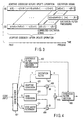
- reference symbol (a) denotes the time waveform of an excitation signal before modification; (b), the time waveform of an excitation signal after modification using an excitation filter; and (c) and (d), amplitude characteristics of the excitation signal (a) and modified excitation signal (b) on the frequency axis.
- the frequency amplitude of the excitation signal u before modification using an excitation filter is almost flat without any tilt on average.
- the frequency amplitude of the excitation signal v modified by the excitation filter 110 is not flat on average but has a tilt, exhibiting a higher amplitude in a low-frequency region.
- this filter has low-pass characteristics.
- an adaptive code vector contributes more to better expression of an excitation source in a low-frequency region, and hence an excitation filter having such characteristics is preferably used to realize high quality.
- the power of an excitation signal having passed through the filter preferably remains the same.
- FIG. 6 schematically shows processing by this excitation filter.
- An excitation filter 610 includes a delay section 611, first multiplier 612, adder 613, and second multiplier 614.
- the delay section 611 delays the output signal v(n) from the excitation filter by one sampling cycle to obtain a signal v(n-1).
- the first multiplier 612 then multiplies the signal v(n-1) by the filter coefficient b1.
- the adder 613 adds the resultant signal to the signal obtained by multiplying the excitation signal u(n) by the filter coefficient b0 using the second multiplier 614, and outputs the resultant signal as the modified excitation signal v(n).
- a value satisfying 0 ⁇ b1 ⁇ 0.25 or the like is preferably set to realize low-pass characteristics.
- FIG. 7 schematically shows processing by this excitation filter.
- An excitation filter 710 includes a delay section 711, multiplier 712, and adder 713.
- the delay section 711 delays the excitation signal v(n) by one sampling cycle to obtain a signal u(n-1).
- the first multiplier 712 then multiplies the signal u(n-1) by a filter coefficient k2.
- the adder 713 adds the excitation signal u(n) to the resultant signal, and outputs the resultant signal as the modified excitation signal v(n).
- a value satisfying 0 ⁇ k2 ⁇ 0.25 or the like is preferably set.
- the gain of the excitation filter can be adjusted.
- a value satisfying 0 ⁇ (c1/c0) ⁇ 0.25 or the like is preferably set.
- FIG. 8 schematically shows processing by this excitation filter.
- An excitation filter 810 includes a delay section 811, first multiplier 812, adder 813, and second multiplier 814.
- the delay section 811 delays the excitation signal v(n) by one sampling cycle to obtain the signal u(n - 1).
- the first multiplier 812 multiplies the signal u(n - 1) by a filter coefficient c1.
- the adder 813 then adds the resultant signal to the signal obtained by multiplying the excitation signal u(n) by a filter coefficient c0 using the second multiplier 814, and outputs the resultant signal as the modified excitation signal v(n).
- the excitation filter need not have fixed characteristics.
- a plurality of excitation filters having different characteristics may be selectively used, or an excitation filter having variable characteristics, e.g., an excitation filter capable of varying the value of the filter coefficient(s) may be used. Note that information transfer must be performed to allow the use of excitation filters having the same characteristics on the encoding and decoding sides.
- a method of changing the filter characteristics of an excitation filter by using the encoded information of a speech signal is available.
- a mechanism of making the filter characteristics of the excitation filter shown in FIG. 1 adaptive on the basis of present or past encoded information can be used.
- a filter characteristic R(f(y), z): f(y) of the excitation filter is a function of a variable y , and y can be expressed as present or past encoded information.
- excitation filters can be switched by selecting one set of excitation filter coefficients from a plurality of sets of excitation filter coefficients.
- an excitation filter By switching the characteristics of an excitation filter on the basis of the encoded information of speech, an excitation filter can be adaptively used in accordance with the features of a speech signal. In addition, there is no need to send additional information required to switch excitation filters.
- An excitation signal used to generate a synthesized speech may be preferably stored in the adaptive codebook without any modification depending on conditions. For this reason, switching of excitation filters or changing of filter characteristics is preferably selected in consideration of the above case as well, in which no excitation filtering is performed.
- the present invention is not limited to those described above, and various excitation filters can be used.
- Synthesized speech can be obtained, which has high quality as compared with a case where an adaptive codebook storing excitation signals without any changes is used.
- a speech encoding/decoding method capable of obtaining a synthesized speech with high quality can be obtained.
Landscapes
- Engineering & Computer Science (AREA)
- Computational Linguistics (AREA)
- Signal Processing (AREA)
- Health & Medical Sciences (AREA)
- Audiology, Speech & Language Pathology (AREA)
- Human Computer Interaction (AREA)
- Physics & Mathematics (AREA)
- Acoustics & Sound (AREA)
- Multimedia (AREA)
- Compression, Expansion, Code Conversion, And Decoders (AREA)
Abstract
Description
- The present invention relates to a speech encoding method and speech decoding method which are used to compression-encode and decode speech signals, audio signals, and the like.
- As a method of compression-encoding speech signals, a CELP (Code-Excited Linear Prediction) scheme is known ("Code-Excited Linear Prediction (CELP): High-quality Speech at Very Low Rates "Rroc. ICASSP '85, 25, 1.1. pp. 937 - 940, 1985).
- According to characteristic features of the CELP scheme, modeling of a speech signal is performed separately for a synthesis filter and an excitation signal for driving the synthesis filter, and distortion is evaluated in accordance with the level of a perceptually weighted speech signal in encoding the excitation signal, thereby making it difficult to perceive encoding distortion. A synthesized speech signal after encoding is generated by passing the excitation signal through the synthesis filter. The excitation signal is generated by combining two code vectors, i.e., an adaptive code vector generated from an adaptive codebook storing past excitation signals and a stochastic vector generated from a stochastic codebook.
- An adaptive code vector mainly represents repetition of a waveform based on a pitch period as a feature of an excitation signal in a voiced speech interval. A stochastic code vector contains a component for compensating for a component contained in an excitation signal which cannot be expressed by an adaptive code vector, and is used to make a synthesized speech signal more natural.
- An adaptive codebook is a codebook using the fact that a repeating waveform based on a pitch period of an excitation signal is similar to the repeating waveform of an immediately preceding excitation signal. More specifically, past excitation signals are stored in the adaptive codebook without any changes, and a past excitation signal is extracted from the adaptive codebook by an amount corresponding to a pitch period. The vector obtained by repeating the extracted signal with a pitch interval at a pitch period up to a signal interval is used as an adaptive code vector. As described above, according to the conventional adaptive codebook, the current adaptive code vector is obtained by directly repeating an excitation signal used in the past. In this conventional method, if the encoding bit rate is decreased to about 4 kbits/s, since an insufficient number of bits are assigned to express an excitation signal, distortion due to encoding is clearly perceived. As a consequence, the speech becomes unclear or noisy. That is, the sound quality considerably deteriorates. Demands have therefore arisen for a high-efficiency encoding scheme that can generate synthesized speech with high quality even if the bit rate is decreased.
- As described above, in the conventional speech encoding method, it is difficult to obtain synthesized speech with high quality at a low bit rate.
- It is an object of the present invention to provide a speech encoding method/speech decoding method which can generate synthesized speech with high quality even at a low bit rate.
- The present inventor has given special consideration to the fact that in pitch period components contained in a voiced speech signal, low frequency components exhibit repetition with a stronger correlation than high frequency components in terms of frequency. That is, pitch repetition components in a low frequency band tend to change slowly, whereas pitch repetition components in a high frequency band tend to change quickly.
- In consideration of the characteristics of the pitch period components contained in the speech signal, therefore, the degree of contribution to a better expression of an excitation signal by an obtained adaptive code vector is generally higher on the low-frequency side than on the high-frequency side. That is, excitation signals in a low frequency band can be stored in an adaptive codebook and reused more effectively than excitation signals in a high frequency band. Therefore, the conventional method is not necessarily effective, in which excitation signals in all frequency bands are stored in an adaptive codebook in the same manner.
- The present invention has been made in consideration of the general tendency that the contributions of adaptive code vectors in different frequency bands vary, and the contributions of adaptive code vectors decrease with an increase in frequency.
- Synthesized speech with high quality can be obtained and excellent synthesized speech can be obtained even at a low bit rate by changing characteristics depending on such frequency bands, i.e., updating an adaptive codebook by using an excitation signal after modification by excitation filter processing (adjusting an output in accordance with a frequency band).
- According to the present invention, there is provided a speech encoding method of generating a synthesized speech signal by using an excitation signal generated by using an adaptive codebook storing a past excitation signal, comprising modifying an excitation signal used to generate a synthesized speech signal by filtering, and storing the modified excitation signal in the adaptive codebook.
- A speech encoding/decoding method is provided, which can synthesize speech with high quality by storing an excitation signal modified by predetermined filter processing in an adaptive codebook instead of storing an excitation signal in the adaptive codebook without any modification as in the conventional method.
- As described above, since an adaptive code vector in a lower frequency band contributes more to an excitation signal, low-pass characteristics are preferably provided. An excitation signal can be generated by using a first code vector obtained from an adaptive codebook (first codebook) reflecting periodicity and a second code vector (e.g., a stochastic code vector) obtained from another kind of codebook (a second codebook, e.g., a stochastic codebook). However, the present invention is not limited to the stochastic codebook, and the number of codebooks used is not limited to two; an excitation signal can be obtained from a plurality of codebooks including an adaptive codebook.
- For example, the present invention can be implemented by a speech encoding method of generating a synthesized speech signal by using an excitation signal generated by using a first code vector obtained from an adaptive codebook storing a past excitation signal and a second code vector obtained from a predetermined codebook (e.g., a stochastic codebook). This speech encoding method comprises selecting code information representing a first code vector by using the adaptive codebook so as to reduce perceptually weighted distortion between a target vector obtained from an input speech signal and a synthesized vector obtained by synthesizing candidate vectors of the first code vector; selecting code information representing a second code vector from the codebook so as to reduce perceptually weighted distortion of the synthesized speech signal; generating an excitation signal by using the selected first and second code vectors; modifying the generated excitation signal by filter processing; and storing the modified excitation signal in the adaptive codebook.
- When an excitation signal is to be generated from an adaptive code vector obtained from an adaptive codebook and a stochastic code vector obtained from a stochastic codebook, an excitation signal before modification is given by, for example, an excitation vector u expressed by the following equation, and is input to a synthesis filter to obtain synthesized speech. Note that the excitation signal is not limited to this.
- Filters with various conditions can be used for filter processing to be performed for this excitation signal before modification. For example, excitation filter processing is performed for the excitation signal before modification by using a recursive filter expressed by R(z) = 1/(1 - klz-1) (k1: filter coefficient) in a z-transform domain, and the result is stored as latest data in the adaptive codebook.
- The excitation vector modified by using such filter processing is given by
- Note that this excitation filter is not limited to a single-order recursive filter, and a multi-order filter or non-recursive filter may be used.
- In addition, characteristics of an excitation filter may change depending on encoding information (synthesis filter information, pitch period, gain information, and the like or input speech signal). In this case, the excitation signal may remain the same before and after modification depending on conditions.
- The present invention can be applied to an electronic apparatus designed to perform digital speech processing, e.g., a handyphone, portable terminal, or personal computer with speech processing.
- According to the present invention, there is provided an electronic apparatus comprising a speech encoder which executes the above speech encoding method, and a speech input device (a direct speech input device such as a microphone or an input device which inputs a speech signal that is externally supplied) for supplying a speech signal to the speech encoder.
- In addition, according to the present invention, there is provided an electronic apparatus comprising a speech decoder which executes the above speech decoding method for the speech signal encoded by the above speech encoding method, and a speech output device (a direct sound device such as a loudspeaker or a speech supply device which supplies a speech signal to an external apparatus) for outputting a speech signal from the speech decoder.
- If an electronic apparatus includes both an encoder and a decoder, the apparatus can encode and decode speech signals. If, however, decoding is not required, the apparatus may include only an encoder together with another means necessary therefor. If only decoding is required, the apparatus may include only a decoder together with another means necessary therefor.
- A handyphone requires both an encoding function and a decoding function because it transmits/receives signals to/from a remote apparatus.
- In base stations and relay stations constituting a telephone network, analog and digital lines must be connected to each other in some cases. In such cases as well, since encoded speech signals are supplied from the digital line side, and analog speech signals before encoding are supplied from the analog line side, encoding and decoding must be performed for the respective operations. Therefore, both an encoding function and a decoding function are required. The present invention can also be applied to an electronic apparatus designed to receive a speech signal from an external apparatus and return the signal to the external apparatus or transfer it to another apparatus upon encoding it.
- This summary of the invention does not necessarily describe all necessary features so that the invention may also be a sub-combination of these described features.
- The invention can be more fully understood from the following detailed description when taken in conjunction with the accompanying drawings, in which:
- FIG. 1 is a block diagram showing speech encoding according to an embodiment of the present invention;
- FIG. 2 is a block diagram showing an excitation filter according to the embodiment of the present invention;
- FIG. 3 is a view for explaining an adaptive codebook according to the embodiment of the present invention;
- FIG. 4 is a block diagram showing speech decoding according to the embodiment of the present invention;
- FIG. 5 is a view for explaining the function of the excitation filter according to the embodiment of the present invention;
- FIG. 6 is a block diagram showing an excitation filter according to the embodiment of the present invention;
- FIG. 7 is a block diagram showing an excitation filter according to the embodiment of the present invention; and
- FIG. 8 is a block diagram showing an excitation filter according to the embodiment of the present invention.
-
- An embodiment of the present invention will be described with reference to the views of the accompanying drawing. FIG. 1 is a schematic block diagram showing a speech encoding method in this embodiment of the present invention. An input speech signal input from a speech input device (not shown) such as a microphone is A/D-converted and processed in units of frames each corresponding to a predetermined period of time. An
LPC analyzer 101 analyzes the framed input speech signal to extract linear predictive coefficients (LPC coefficients). A synthesisfilter information encoder 102 encodes the extracted LPC coefficients and outputs synthesis filter information A to amultiplexer 103. The linear predictive coefficients are used as synthesis filter coefficients (α(i): the order of a filter is set to, for example, 10, as needed) of asynthesis filter section 104. Subsequently, for example, each frame is divided into subframes corresponding to predetermined time intervals to obtain pitch period information L, stochastic code C, and gain information G. Anadaptive codebook 105 stores past excitation signals (past excitation signals modified by filter processing in the present invention). Upon reception of a pitch period as a candidate, theadaptive codebook 105 retraces by a length corresponding to the pitch period and extracts an excitation signal. Theadaptive codebook 105 generates an adaptive code vector by repeating this signal. - In searching for a pitch period, a perceptually weighted distortion computation section 109 calculates the waveform distortion caused when the
synthesis filter section 104 synthesizes an adaptive code vector corresponding to a pitch period candidate, and acode selector 106 searches for a pitch period in which the distortion of the perceptually weighted synthesized waveform is reduced more. Although the value obtained by open loop pitch analysis on a frame basis can be used as the initial value of a candidate pitch, the present invention is not limited to this. - The pitch period determined by the adaptive codebook search is converted into the pitch period information L and output to the
multiplexer 103. - A
stochastic codebook 107 outputs a stochastic vector corresponding to the supplied stochastic code as a stochastic code vector candidate. In some scheme, a stochastic codebook is structured so as not to directly store stochastic code vectors. For example, a scheme using an Algebraic codebook is available. This Algebraic codebook is designed to express a code vector by a combination of pulse position information and polarity information with the amplitudes of a predetermined number of pulses being limited to +1 and -1. According to characteristic features of the Algebraic codebook, a codebook can be expressed by a small memory capacity because any code vectors themselves need not be stored, and stochastic components contained in excitation information can be expressed with relatively high quality in spite of a small calculation amount required for code vector selection. - A scheme using an Algebraic codebook to encode excitation signals is called an ACELP scheme or ACELP-based scheme and known as a scheme of obtaining a synthesized speech with little distortion.
- In searching for the stochastic code C, the perceptually weighted distortion computation section 109 computes the perceptually weighted distortion contained in the waveform formed when a stochastic code vector corresponding to a stochastic code candidate is synthesized by the
synthesis filter section 104, and thecode selector 106 searches for a stochastic code with which the distortion of this perceptually weighted synthesized waveform is reduced more. The found stochastic code C is output to themultiplexer 103. - In this embodiment, the expression "stochastic codebook" is used. Obviously, however, a stochastic code vector expressed by this codebook need not always be stochastic. For example, this code vector may be a pulse excitation code vector as in an Algebraic codebook.
- A
gain codebook 108 stores candidates for a gain G0 used for an adaptive code vector and a gain G1 used for a stochastic code vector. For example, in searching for a gain code, the perceptually weighted distortion computation section 109 computes the perceptually weighted distortion contained in the waveform formed when the excitation code vector obtained by adding the adaptive code vector and stochastic code vector multiplied by gain candidates, respectively, is synthesized by the synthesis filter. Thecode selector 106 searches for a gain code with which the distortion of the perceptually weighted synthesized waveform is reduced more. - The found gain code G is output to the
multiplexer 103. Various methods can be used to determine the above pitch period information L, stochastic code C, and gain information G. For example, the following method can be used. - The pitch period information L is obtained by an adaptive codebook search (adaptive code vector). The stochastic code C (stochastic code vector) is then obtained by making a stochastic codebook search so as to reduce the difference between the target vector and the vector obtained by multiplying the obtained adaptive code vector by a temporary gain (e.g., optimal gain). The gain information G (gain code vector) is obtained by making a gain codebook search using the obtained adaptive code vector and stochastic code vector.
- Apparently, the present invention is not limited to the above method. By using the pitch period information L, stochastic code C, and gain information G found in this manner, an excitation signal (excitation vector) u is generated according to equation (1):
adaptive codebook 105 in correspondence with the pitch period information L, x1 is the stochastic code vector obtained from thestochastic codebook 107 in correspondence with the stochastic code C, G0 is a gain which is obtained from thegain codebook 108 in correspondence with the gain information G and multiplied with the adaptive code vector in amultiplier 111, and G1 is a gain which is obtained from thegain codebook 108 in correspondence with the gain information G and multiplied with the stochastic code vector in amultiplier 112. The outputs of themultipliers adder 113. - The
synthesis filter section 104 generates a synthesized speech by performing synthesis filtering expressed as 1/A(z):A(z) = 1 + Σ α (i)z-' where α(i) is a synthesis filter coefficient (synthesis filter information A) in a z-transform domain with respect to the input of the excitation signal u obtained in this manner. This synthesized speech and input speech are subtracted from each other in anadder 114, and the above various selection/determination steps are then performed to reduce the difference, i.e., the distortion of the perceptually weighted synthesized waveform calculated by the perceptually weighted distortion computation section 109. - The obtained excitation vector u is modified (or corrected) by the
excitation filter 110 and stored in theadaptive codebook 105. Various methods can be used for this modification (or correction). For example, the vector can be modified by directly filtering it using an excitation filter having predetermined characteristics. As this excitation filter, for example, a single-order recursive filter expressed by equation (2) given below can be used: - When an excitation filter having such output characteristics is used, an excitation signal v(n) after modification can be given by
- FIG. 2 schematically shows processing by this excitation filter. The input excitation signal u(n) is input to an
excitation filter 210 including adelay device 211,multiplier 212, andadder 213. In theexcitation filter 210, themultiplier 212 multiplies a signal v(n-1), obtained by delaying the output signal v(n) from the excitation filter using thedelay device 211, by the filter coefficient k1, and theadder 213 then adds the excitation signal u(n) to the product, thereby outputting the resultant signal as the modified excitation signal v(n). - As described above, since a better effect can be obtained by increasing the degree of contribution in a low frequency band, a better effect can be obtained by providing low-pass characteristics. According to experiments, a value satisfying 0 < k1 < 0.25 or the like is preferably used. The excitation signal v(n) modified in this manner is stored as latest information in the adaptive codebook. The adaptive codebook is updated by being shifted by N samples as a whole so as to discard the oldest excitation signal data and store the latest excitation signal data. The latest data is added in this manner. FIG. 3 is a schematic view showing this state. The adaptive codebook before update operation is made up of v(-K)v(-K+1), ..., v(-K+N-1)v(-K+N)v(-K+N+1), ..., v(-2)v(-1), where N is the number of excitation vectors and K is the number of excitation signal data stored in the adaptive codebook. The oldest excitation signal is v(-K)v(-K+1), ..., v(-K+N-1), which is discarded. The data "v(0)v(1), ..., v(N-1)" obtained from the latest excitation signal "u(0)u(1), ..., u(N-1)" before modification by excitation filtering [v(n) = u(n) + k1v(n-1): (n = 0, ..., N-1)] is stored in the adaptive codebook as the latest data.
- The synthesis filter information A, pitch period information L, stochastic code C, and gain information G obtained by the above encoding method are multiplexed, and the multiplexed encoded output is sent out.
- Decoding to be performed upon reception of this encoded information will be described below with reference to FIG. 4. A
demultiplexer 401 demultiplexes the encoded input to obtain the synthesis filter information A, linear predictive pitch period information L, stochastic code C, and gain information G. These pieces of information are respectively sent out to a synthesisfilter information decoder 402,adaptive codebook 403,stochastic codebook 404, and gaincodebook 405. - The synthesis
filter information decoder 402 obtains a linear predictive coefficient (LPC) on the basis of the obtained synthesis filter information A, reconstructs the same LPC coefficient as that on the encoding side, and sends out the LPC coefficient to asynthesis filter section 406. Theadaptive codebook 403 stores past excitation signals like the codebook on the encoding side. Theadaptive codebook 403 retraces from the latest signal by a length corresponding to the pitch period L and extracts an excitation signal. Theadaptive codebook 403 generate an adaptive code vector by repeating this signal. - The
stochastic codebook 404 outputs a stochastic code vector corresponding to the stochastic code C on the basis of the code C. Thegain codebook 405 outputs the gain G0 for an adaptive code vector and the gain G1 for a stochastic code vector on the basis of the gain code G. - The adaptive code vector obtained in the above manner is multiplied by the gain G0 in a
multiplier 408, and the stochastic code vector is multiplied by the gain G1 in amultiplier 409. These vectors are then added by anadder 410, and the resultant signal is input as the excitation signal u to asynthesis filter section 406. This operation is equivalent toequation 1 in encoding operation. Thesynthesis filter section 406 performs synthesis filter processing represented by 1/A(z) for the input of the excitation signal vector (vector obtained by multiplying the respective vectors by gains) based on the adaptive code vector and stochastic code vector in the same manner as on the encoding side, thereby generating a synthesized speech. - Note that an excitation signal v modified by an
excitation filter 407 on the basis of the generated excitation signal u is stored as latest data in the adaptive codebook as in encoding operation. That is, the adaptive codebook having identical information to that on the encoding side is also held on the decoding side. By storing the excitation signal modified by the excitation filter in the adaptive codebook on the decoding side as well, a speech signal with little perceptual distortion, obtained on the encoding side, can be faithfully reproduced. - The functional role of the excitation filter in encoding/decoding operation of the present invention will be described with reference to FIG. 5. Referring to FIG. 5, reference symbol (a) denotes the time waveform of an excitation signal before modification; (b), the time waveform of an excitation signal after modification using an excitation filter; and (c) and (d), amplitude characteristics of the excitation signal (a) and modified excitation signal (b) on the frequency axis.
- As indicated by the dashed line, the frequency amplitude of the excitation signal u before modification using an excitation filter is almost flat without any tilt on average. In contrast to this, the frequency amplitude of the excitation signal v modified by the
excitation filter 110 is not flat on average but has a tilt, exhibiting a higher amplitude in a low-frequency region. This indicates that the frequency characteristics of the excitation filter are equivalent to those represented by the dashed line indicated by "(d)" in FIG. 5. In general, this filter has low-pass characteristics. - As described above, an adaptive code vector contributes more to better expression of an excitation source in a low-frequency region, and hence an excitation filter having such characteristics is preferably used to realize high quality. In addition, the power of an excitation signal having passed through the filter preferably remains the same. In this case, an excitation filter may be formed as follows:
- By using an excitation filter having such output characteristics, the excitation signal v(n) after modification can be expressed by
- FIG. 6 schematically shows processing by this excitation filter. An
excitation filter 610 includes adelay section 611,first multiplier 612,adder 613, andsecond multiplier 614. Thedelay section 611 delays the output signal v(n) from the excitation filter by one sampling cycle to obtain a signal v(n-1). Thefirst multiplier 612 then multiplies the signal v(n-1) by the filter coefficient b1. Theadder 613 adds the resultant signal to the signal obtained by multiplying the excitation signal u(n) by the filter coefficient b0 using thesecond multiplier 614, and outputs the resultant signal as the modified excitation signal v(n). In this case as well, a value satisfying 0 < b1 < 0.25 or the like is preferably set to realize low-pass characteristics. - The excitation filter to be used is not limited to the above recursive filter, and the present invention can use a non-recursive filter like the one expressed by
- In this case, an excitation signal v(n) after modification which is obtained by inputting the excitation signal u to the excitation filter is given by
- FIG. 7 schematically shows processing by this excitation filter.
- An
excitation filter 710 includes adelay section 711,multiplier 712, andadder 713. Thedelay section 711 delays the excitation signal v(n) by one sampling cycle to obtain a signal u(n-1). Thefirst multiplier 712 then multiplies the signal u(n-1) by a filter coefficient k2. Theadder 713 adds the excitation signal u(n) to the resultant signal, and outputs the resultant signal as the modified excitation signal v(n). - As described above, since a better effect can be obtained by increasing the degree of contribution in a low frequency band, a better effect can be obtained by providing low-pass characteristics. According to experiments, a value satisfying 0 < k2 < 0.25 or the like is preferably set. In this case as well, the gain of the excitation filter can be adjusted. In this case, the following excitation filter may be used:
- In this case, the excitation signal v(n) after modification which is obtained by inputting the excitation signal u to the excitation filter is given by
- The gain of the excitation filter can be set to 1 by setting c0 + c1 = 1. In this case as well, as described above, since a better effect can be obtained by increasing the degree of contribution in a low frequency band, a better effect can be obtained by providing low-pass characteristics for the excitation filter. A value satisfying 0 < (c1/c0) < 0.25 or the like is preferably set.
- FIG. 8 schematically shows processing by this excitation filter. An
excitation filter 810 includes adelay section 811,first multiplier 812,adder 813, andsecond multiplier 814. Thedelay section 811 delays the excitation signal v(n) by one sampling cycle to obtain the signal u(n - 1). Thefirst multiplier 812 multiplies the signal u(n - 1) by a filter coefficient c1. Theadder 813 then adds the resultant signal to the signal obtained by multiplying the excitation signal u(n) by a filter coefficient c0 using thesecond multiplier 814, and outputs the resultant signal as the modified excitation signal v(n). - The excitation filter need not have fixed characteristics. A plurality of excitation filters having different characteristics may be selectively used, or an excitation filter having variable characteristics, e.g., an excitation filter capable of varying the value of the filter coefficient(s) may be used. Note that information transfer must be performed to allow the use of excitation filters having the same characteristics on the encoding and decoding sides.
- For example, a method of changing the filter characteristics of an excitation filter by using the encoded information of a speech signal is available. A mechanism of making the filter characteristics of the excitation filter shown in FIG. 1 adaptive on the basis of present or past encoded information (A, L, G, and the like) can be used. In this case, a filter characteristic R(f(y), z): f(y) of the excitation filter is a function of a variable y, and y can be expressed as present or past encoded information. Alternatively, excitation filters can be switched by selecting one set of excitation filter coefficients from a plurality of sets of excitation filter coefficients.
- By switching the characteristics of an excitation filter on the basis of the encoded information of speech, an excitation filter can be adaptively used in accordance with the features of a speech signal. In addition, there is no need to send additional information required to switch excitation filters.
- An excitation signal used to generate a synthesized speech may be preferably stored in the adaptive codebook without any modification depending on conditions. For this reason, switching of excitation filters or changing of filter characteristics is preferably selected in consideration of the above case as well, in which no excitation filtering is performed. The present invention is not limited to those described above, and various excitation filters can be used. By updating the adaptive codebook with excitation signals having undergone modification by the excitation filter, an adaptive codebook that places emphasis on a portion exhibiting great contribution to an excitation signal can be obtained.
- Synthesized speech can be obtained, which has high quality as compared with a case where an adaptive codebook storing excitation signals without any changes is used.
- As has been described above, according to the present invention, a speech encoding/decoding method capable of obtaining a synthesized speech with high quality can be obtained.
Claims (23)
- A speech encoding method characterized by comprising:generating an excitation signal using an adaptive codebook storing a past excitation signal;generating a synthesized speech signal using the excitation signal;modifying the excitation signal used to generate the synthesized speech signal by filter processing; andstoring the modified excitation signal in the adaptive codebook.
- A method according to claim 1, characterized in that the filter processing is executed by an excitation filter having low-pass characteristics.
- A method according to claim 1, characterized in that the modifying step is performed by a recursive filter expressed by R(z) = 1/(1 - klz-1) (k1: filter coefficient) in a z-transform domain.
- A method according to claim 1, characterized in that the excitation signal generating step generates the excitation signal by using a first code vector generated from the adaptive codebook and a second code vector generated from a codebook different from the adaptive codebook.
- A speech encoding method characterized by comprising:generating an excitation signal by using a first code vector obtained from an adaptive codebook storing a past excitation signal and a second code vector obtained from another codebook;selecting code information representing a first code vector by using the adaptive codebook so as to reduce perceptually weighted distortion between a target vector obtained from an input speech signal and a synthesized vector obtained from a candidate vector of the first code vector;selecting code information representing a second code vector from the codebook so as to reduce perceptually weighted distortion of the synthesized speech signal;generating an excitation signal by using the selected first and second code vectors;modifying the generated excitation signal by filter processing; andstoring the modified excitation signal in the adaptive codebook.
- A method according to claim 5, characterized in that the modifying step is performed by a recursive filter expressed by R(z) = 1/(1 - klz-1) (k1: filter coefficient) in a z-transform domain.
- A method according to claim 5, characterized in that the filter processing is executed by an excitation filter having low-pass characteristics.
- A speech decoding method characterized by comprising:generating an excitation signal using an adaptive codebook storing a past excitation signal;generating a synthesized speech signal using the excitation signal;modifying the excitation signal used to generate the synthesized speech signal by filter processing; andstoring the modified excitation signal in the adaptive codebook.
- A method according to claim 8, characterized in that the filter processing is executed by an excitation filter having low-pass characteristics.
- A method according to claim 8, characterized in that the modifying step is performed by a recursive filter expressed by R(z) = 1/(1 - klz-1) (k1: filter coefficient) in a z-transform domain.
- A method according to claim 8, characterized in that the excitation signal generating step generates the excitation signal by using a first code vector generated from the adaptive codebook and a second code vector generated from a codebook different from the adaptive codebook.
- An electronic apparatus characterized by comprising:a speech encoder (FIG. 1) configured to execute the speech encoding method according to claim 1; anda speech input device configured to supply a speech signal to said speech encoder.
- An electronic apparatus characterized by comprising:a speech decoder (FIG. 4) configured to execute the speech decoding method according to claim 8; anda speech output device configured to output a speech signal from said speech decoder.
- An electronic device characterized by comprising:a speech encoder (FIG. 1) configured to execute the speech encoding method according to claim 1;a speech decoder (FIG. 4) configured to execute a speech decoding method comprising:generating an excitation signal using an adaptive codebook storing a past excitation signal;generating a synthesized speech signal using the excitation signal;modifying the excitation signal used to generate the synthesized speech signal by filter processing; andstoring the modified excitation signal in the adaptive codebook.;a speech input device configured to supply a speech signal to said speech encoder; anda speech output device configured to output a speech signal from said speech decoder.
- A speech encoding method characterized by comprising:generating an excitation signal by using a first code vector obtained from an adaptive codebook storing a past excitation signal and a second code vector obtained from another codebook;modifying the excitation signal by filter processing; andstoring the modified excitation signal in the adaptive codebook.
- A method according to claim 15, characterized in that the filter processing is executed by an excitation filter having low-pass characteristics.
- A method according to claim 15, characterized in that the modifying step is performed by a recursive filter expressed by R(z) = 1/(1 - klz-1) (k1: filter coefficient) in a z-transform domain.
- A speech encoding apparatus characterized by comprising:an adaptive codebook (105) configured to store a past excitation signal;a synthesized speech signal generator (104) configured to generate a synthesized speech signal using an excitation signal generated by using said adaptive codebook; andan excitation filter (110) configured to modify the excitation signal by filter processing and store a modified excitation signal in said adaptive codebook.
- A speech encoding apparatus characterized by comprising:a first codebook (105) configured to store a past excitation signal and generate a first code vector;a second codebook (107) configured to generate a second code vector;a first code vector selector (106) configured to select code information representing the first code vector by using said first codebook so as to reduce perceptually weighted distortion between a target vector obtained from an input speech signal and a synthesized vector obtained from a candidate vector of the first code vector;a second code vector selector (106) configured to select code information representing the second code vector from said second codebook so as to reduce perceptually weighted distortion of the synthesized speech signal;an excitation signal generator (113) configured to generate an excitation signal by using the selected first and second code vectors;an excitation signal modifier (110) configured to modify the generated excitation signal by filter processing, and store a modified excitation signal in said first codebook.
- A speech decoding apparatus characterized by comprising:an adaptive codebook (403) configured to store a past excitation signal;a synthesized speech signal generator (406) configured to generate a synthesized speech signal using an excitation signal generated by using said adaptive codebook; andan excitation filter (407) configured to modify the excitation signal by filter processing and store a modified excitation signal in said adaptive codebook.
- An electronic apparatus characterized by comprising:a speech encoder (FIG. 1) according to claim 18; anda speech input device configured to supply a speech signal to said speech encoder.
- An electronic apparatus characterized by comprising:a speech decoder (FIG. 4) according to claim 20; anda speech output device configured to output a speech signal from said speech decoder.
- An electronic device characterized by comprising:a speech encoder (FIG. 1) according to claim 18;a speech decoder (FIG. 4) comprising:an adaptive codebook (403) configured to store a past excitation signal;a synthesized speech signal generator (406) configured to generate a synthesized speech signal using an excitation signal generated by using said adaptive codebook; andan excitation filter (407) configured to modify the excitation signal by filter processing and store a modified excitation signal in said adaptive codebook;a speech input device configured to supply a speech signal to said speech encoder; anda speech output device configured to output a speech signal from said speech decoder.
Applications Claiming Priority (2)
| Application Number | Priority Date | Filing Date | Title |
|---|---|---|---|
| JP2000320679 | 2000-10-20 | ||
| JP2000320679A JP3462464B2 (en) | 2000-10-20 | 2000-10-20 | Audio encoding method, audio decoding method, and electronic device |
Publications (3)
| Publication Number | Publication Date |
|---|---|
| EP1204094A2 true EP1204094A2 (en) | 2002-05-08 |
| EP1204094A3 EP1204094A3 (en) | 2004-01-14 |
| EP1204094B1 EP1204094B1 (en) | 2006-12-27 |
Family
ID=18798927
Family Applications (1)
| Application Number | Title | Priority Date | Filing Date |
|---|---|---|---|
| EP01106359A Expired - Lifetime EP1204094B1 (en) | 2000-10-20 | 2001-03-16 | Excitation signal low pass filtering for speech coding |
Country Status (4)
| Country | Link |
|---|---|
| US (1) | US6842732B2 (en) |
| EP (1) | EP1204094B1 (en) |
| JP (1) | JP3462464B2 (en) |
| DE (1) | DE60125491T2 (en) |
Families Citing this family (6)
| Publication number | Priority date | Publication date | Assignee | Title |
|---|---|---|---|---|
| EP1959434B1 (en) * | 1999-08-23 | 2013-03-06 | Panasonic Corporation | Speech encoder |
| JP2004061646A (en) * | 2002-07-25 | 2004-02-26 | Fujitsu Ltd | Speech encoding device and method having tfo (tandem free operation)function |
| JP4433668B2 (en) * | 2002-10-31 | 2010-03-17 | 日本電気株式会社 | Bandwidth expansion apparatus and method |
| JP5127170B2 (en) * | 2006-07-07 | 2013-01-23 | 株式会社東芝 | Decoding device and spectrum shaping method |
| LT2774145T (en) * | 2011-11-03 | 2020-09-25 | Voiceage Evs Llc | Improving non-speech content for low rate celp decoder |
| US20210366461A1 (en) * | 2020-05-20 | 2021-11-25 | Resemble.ai | Generating speech signals using both neural network-based vocoding and generative adversarial training |
Family Cites Families (9)
| Publication number | Priority date | Publication date | Assignee | Title |
|---|---|---|---|---|
| JPH04352199A (en) | 1991-05-30 | 1992-12-07 | Fujitsu Ltd | Speech encoding and decoding system |
| US5621852A (en) * | 1993-12-14 | 1997-04-15 | Interdigital Technology Corporation | Efficient codebook structure for code excited linear prediction coding |
| JPH08179796A (en) * | 1994-12-21 | 1996-07-12 | Sony Corp | Voice coding method |
| JPH10149200A (en) | 1996-11-20 | 1998-06-02 | Olympus Optical Co Ltd | Linear predictive encoder |
| US6202046B1 (en) * | 1997-01-23 | 2001-03-13 | Kabushiki Kaisha Toshiba | Background noise/speech classification method |
| US6041297A (en) * | 1997-03-10 | 2000-03-21 | At&T Corp | Vocoder for coding speech by using a correlation between spectral magnitudes and candidate excitations |
| US6233550B1 (en) * | 1997-08-29 | 2001-05-15 | The Regents Of The University Of California | Method and apparatus for hybrid coding of speech at 4kbps |
| JP2000122698A (en) | 1998-10-19 | 2000-04-28 | Mitsubishi Electric Corp | Voice encoder |
| US6311154B1 (en) * | 1998-12-30 | 2001-10-30 | Nokia Mobile Phones Limited | Adaptive windows for analysis-by-synthesis CELP-type speech coding |
-
2000
- 2000-10-20 JP JP2000320679A patent/JP3462464B2/en not_active Expired - Fee Related
-
2001
- 2001-03-13 US US09/803,998 patent/US6842732B2/en not_active Expired - Lifetime
- 2001-03-16 DE DE60125491T patent/DE60125491T2/en not_active Expired - Lifetime
- 2001-03-16 EP EP01106359A patent/EP1204094B1/en not_active Expired - Lifetime
Non-Patent Citations (3)
| Title |
|---|
| KROON P ET AL: "Strategies for improving the performance of CELP coders at low bit rates (speech analysis)" PROC OF ICASSP 1988, 11 April 1988 (1988-04-11), pages 151-154, XP010073075 * |
| TOMOHIKO TANIGUCHI ET AL: "PITCH SHARPENING FOR PERCEPTUALLY IMPROVED CELP, AND THE SPARSE- DELTA CODEBOOK FOR REDUCED COMPUTATION" SPEECH PROCESSING 1. TORONTO, MAY 14 - 17, 1991, INTERNATIONAL CONFERENCE ON ACOUSTICS, SPEECH & SIGNAL PROCESSING. ICASSP, NEW YORK, IEEE, US, vol. 1 CONF. 16, 14 May 1991 (1991-05-14), pages 241-244, XP000245212 ISBN: 0-7803-0003-3 * |
| WANG S ET AL: "IMPROVED EXCITATION FOR PHONETICALLY-SEGMENTED VXC SPEECH CODING BELOW 4 KB/S" COMMUNICATIONS: CONNECTING THE FUTURE. SAN DIEGO, DEC. 2 - 5, 1990, PROCEEDINGS OF THE GLOBAL TELECOMMUNICATIONS CONFERENCE AND EXHIBITION(GLOBECOM), NEW YORK, IEEE, US, vol. 2, 2 December 1990 (1990-12-02), pages 946-950, XP000220915 ISBN: 0-87942-632-2 * |
Also Published As
| Publication number | Publication date |
|---|---|
| EP1204094A3 (en) | 2004-01-14 |
| EP1204094B1 (en) | 2006-12-27 |
| JP3462464B2 (en) | 2003-11-05 |
| DE60125491T2 (en) | 2007-10-04 |
| US20020052745A1 (en) | 2002-05-02 |
| US6842732B2 (en) | 2005-01-11 |
| JP2002132300A (en) | 2002-05-09 |
| DE60125491D1 (en) | 2007-02-08 |
Similar Documents
| Publication | Publication Date | Title |
|---|---|---|
| US6427135B1 (en) | Method for encoding speech wherein pitch periods are changed based upon input speech signal | |
| AU714752B2 (en) | Speech coder | |
| EP0409239B1 (en) | Speech coding/decoding method | |
| KR0169020B1 (en) | Speech encoding apparatus, speech decoding apparatus, speech coding and decoding method and a phase amplitude characteristic extracting apparatus for carrying out the method | |
| US7006966B2 (en) | Speech encoding apparatus, speech encoding method, speech decoding apparatus, and speech decoding method | |
| US5864798A (en) | Method and apparatus for adjusting a spectrum shape of a speech signal | |
| EP0763818B1 (en) | Formant emphasis method and formant emphasis filter device | |
| KR100304682B1 (en) | Fast Excitation Coding for Speech Coders | |
| JP2002202799A (en) | Voice code conversion apparatus | |
| EP1096476B1 (en) | Speech signal decoding | |
| JP3343082B2 (en) | CELP speech encoder | |
| JP3746067B2 (en) | Speech decoding method and speech decoding apparatus | |
| US6842732B2 (en) | Speech encoding and decoding method and electronic apparatus for synthesizing speech signals using excitation signals | |
| JPH0944195A (en) | Voice encoding device | |
| JPH1097294A (en) | Voice coding device | |
| JP3888097B2 (en) | Pitch cycle search range setting device, pitch cycle search device, decoding adaptive excitation vector generation device, speech coding device, speech decoding device, speech signal transmission device, speech signal reception device, mobile station device, and base station device | |
| US5719993A (en) | Long term predictor | |
| CA2542137C (en) | Harmonic noise weighting in digital speech coders | |
| JP3490325B2 (en) | Audio signal encoding method and decoding method, and encoder and decoder thereof | |
| KR100341398B1 (en) | Codebook searching method for CELP type vocoder | |
| JPH0258100A (en) | Voice encoding and decoding method, voice encoder, and voice decoder | |
| JPH113098A (en) | Method and device of encoding speech | |
| JP3249144B2 (en) | Audio coding device | |
| JPH06202698A (en) | Adaptive post filter | |
| JPH07168596A (en) | Voice recognizing device |
Legal Events
| Date | Code | Title | Description |
|---|---|---|---|
| PUAI | Public reference made under article 153(3) epc to a published international application that has entered the european phase |
Free format text: ORIGINAL CODE: 0009012 |
|
| 17P | Request for examination filed |
Effective date: 20010316 |
|
| AK | Designated contracting states |
Kind code of ref document: A2 Designated state(s): AT BE CH CY DE DK ES FI FR GB GR IE IT LI LU MC NL PT SE TR |
|
| AX | Request for extension of the european patent |
Free format text: AL;LT;LV;MK;RO;SI |
|
| PUAL | Search report despatched |
Free format text: ORIGINAL CODE: 0009013 |
|
| AK | Designated contracting states |
Kind code of ref document: A3 Designated state(s): AT BE CH CY DE DK ES FI FR GB GR IE IT LI LU MC NL PT SE TR |
|
| AX | Request for extension of the european patent |
Extension state: AL LT LV MK RO SI |
|
| 17Q | First examination report despatched |
Effective date: 20040420 |
|
| AKX | Designation fees paid |
Designated state(s): DE FR GB |
|
| GRAP | Despatch of communication of intention to grant a patent |
Free format text: ORIGINAL CODE: EPIDOSNIGR1 |
|
| RTI1 | Title (correction) |
Free format text: EXCITATION SIGNAL LOW PASS FILTERING FOR SPEECH CODING |
|
| GRAS | Grant fee paid |
Free format text: ORIGINAL CODE: EPIDOSNIGR3 |
|
| GRAA | (expected) grant |
Free format text: ORIGINAL CODE: 0009210 |
|
| AK | Designated contracting states |
Kind code of ref document: B1 Designated state(s): DE FR GB |
|
| REG | Reference to a national code |
Ref country code: GB Ref legal event code: FG4D |
|
| REF | Corresponds to: |
Ref document number: 60125491 Country of ref document: DE Date of ref document: 20070208 Kind code of ref document: P |
|
| ET | Fr: translation filed | ||
| PLBE | No opposition filed within time limit |
Free format text: ORIGINAL CODE: 0009261 |
|
| STAA | Information on the status of an ep patent application or granted ep patent |
Free format text: STATUS: NO OPPOSITION FILED WITHIN TIME LIMIT |
|
| 26N | No opposition filed |
Effective date: 20070928 |
|
| REG | Reference to a national code |
Ref country code: FR Ref legal event code: PLFP Year of fee payment: 16 |
|
| PGFP | Annual fee paid to national office [announced via postgrant information from national office to epo] |
Ref country code: DE Payment date: 20160308 Year of fee payment: 16 |
|
| PGFP | Annual fee paid to national office [announced via postgrant information from national office to epo] |
Ref country code: FR Payment date: 20160208 Year of fee payment: 16 Ref country code: GB Payment date: 20160316 Year of fee payment: 16 |
|
| REG | Reference to a national code |
Ref country code: DE Ref legal event code: R119 Ref document number: 60125491 Country of ref document: DE |
|
| GBPC | Gb: european patent ceased through non-payment of renewal fee |
Effective date: 20170316 |
|
| REG | Reference to a national code |
Ref country code: FR Ref legal event code: ST Effective date: 20171130 |
|
| PG25 | Lapsed in a contracting state [announced via postgrant information from national office to epo] |
Ref country code: FR Free format text: LAPSE BECAUSE OF NON-PAYMENT OF DUE FEES Effective date: 20170331 Ref country code: DE Free format text: LAPSE BECAUSE OF NON-PAYMENT OF DUE FEES Effective date: 20171003 |
|
| PG25 | Lapsed in a contracting state [announced via postgrant information from national office to epo] |
Ref country code: GB Free format text: LAPSE BECAUSE OF NON-PAYMENT OF DUE FEES Effective date: 20170316 |