JP4331577B2 - Drawing apparatus and drawing method - Google Patents
Drawing apparatus and drawing method Download PDFInfo
- Publication number
- JP4331577B2 JP4331577B2 JP2003407005A JP2003407005A JP4331577B2 JP 4331577 B2 JP4331577 B2 JP 4331577B2 JP 2003407005 A JP2003407005 A JP 2003407005A JP 2003407005 A JP2003407005 A JP 2003407005A JP 4331577 B2 JP4331577 B2 JP 4331577B2
- Authority
- JP
- Japan
- Prior art keywords
- roller
- recording drum
- outer peripheral
- peripheral surface
- recording
- Prior art date
- Legal status (The legal status is an assumption and is not a legal conclusion. Google has not performed a legal analysis and makes no representation as to the accuracy of the status listed.)
- Expired - Fee Related
Links
Images


Classifications
-
- G—PHYSICS
- G03—PHOTOGRAPHY; CINEMATOGRAPHY; ANALOGOUS TECHNIQUES USING WAVES OTHER THAN OPTICAL WAVES; ELECTROGRAPHY; HOLOGRAPHY
- G03B—APPARATUS OR ARRANGEMENTS FOR TAKING PHOTOGRAPHS OR FOR PROJECTING OR VIEWING THEM; APPARATUS OR ARRANGEMENTS EMPLOYING ANALOGOUS TECHNIQUES USING WAVES OTHER THAN OPTICAL WAVES; ACCESSORIES THEREFOR
- G03B27/00—Photographic printing apparatus
Description
この発明は、シート状の記録材料をドラムの外周面に固定し、当該記録材料に描画を行う描画装置に関する。 The present invention relates to a drawing apparatus that fixes a sheet-like recording material to an outer peripheral surface of a drum and performs drawing on the recording material.
種々の記録材料にレーザ光を照射して描画を行うために描画装置が用いられている。ドラム型の描画装置では、主走査方向に回転可能な記録ドラム上に記録材料が装着され、レーザダイオード等を備えた記録ヘッドが記録ドラムの回転軸と平行な副走査方向に移動して感光材料に対して描画を行う。 A drawing apparatus is used to perform drawing by irradiating various recording materials with laser light. In a drum-type drawing apparatus, a recording material is mounted on a recording drum that can be rotated in the main scanning direction, and a recording head including a laser diode or the like moves in a sub-scanning direction parallel to the rotation axis of the recording drum. Draw for.
ドラム形の描画装置では、記録材料の先端および後端をクランプで押圧固定することによりドラム回りに記録材料を固定するようにしている。 In the drum-type drawing apparatus, the recording material is fixed around the drum by pressing and fixing the front end and the rear end of the recording material with a clamp.
また、このような装置でスクイジーローラで押圧しながら、記録材料をドラム回りに巻き付けたり、ドラムから取り外したりすることも行われている(例えば、特許文献1参照)。 In addition, the recording material is wound around the drum or removed from the drum while being pressed with a squeegee roller in such an apparatus (see, for example, Patent Document 1).
従来の装置においては、記録材料の先端をクランプで固定した記録ドラムを回転させながら当該記録材料を順次記録ドラムに巻き付けていく。その際、記録材料の先端を固定するクランプがスクイジーローラと干渉するという問題が生じていた。この問題を避けるため、記録材料の装着中に記録ドラムの回転を一旦停止させ、スクイジーローラをクランプに干渉しない位置まで退避させ、その後、記録ドラムの回転を再開するという動作を行っている。しかし、これらの動作により記録材料の装着に要する時間が長くなるという別の問題が発生する。なお、記録材料を記録ドラムから取りはずす際にも同様の問題が生じる。 In the conventional apparatus, the recording material is sequentially wound around the recording drum while rotating the recording drum in which the tip of the recording material is fixed by a clamp. At that time, there has been a problem that the clamp for fixing the leading end of the recording material interferes with the squeegee roller. In order to avoid this problem, the operation of temporarily stopping the rotation of the recording drum while the recording material is being loaded, retracting the squeegee roller to a position where it does not interfere with the clamp, and then restarting the rotation of the recording drum is performed. However, these operations cause another problem that the time required for mounting the recording material becomes longer. The same problem occurs when the recording material is removed from the recording drum.
したがって、本発明は、ドラム型の描画装置において、記録ドラムに対する記録材料の着脱作業の効率を向上させ、以て描画装置の稼働効率を改善することをその目的とする。 Accordingly, an object of the present invention is to improve the efficiency of the operation of attaching and detaching the recording material to and from the recording drum in the drum-type drawing apparatus, thereby improving the operating efficiency of the drawing apparatus.
請求項1記載の発明は、シート状の記録材料を装着しつつ軸まわりの所定方向に回転する記録ドラムと、前記記録ドラムの外周面に沿って当該外周面に対して相対的に移動して前記記録材料を前記外周面に向けて押圧するローラと、当該ローラを前記記録ドラムに対して接近する方向および離隔する方向に移動させる駆動手段と、前記記録ドラムに装着された記録材料に対してレーザ光を照射して所望の画像を形成する記録ヘッドと、を有する描画装置であって、前記ローラが前記記録ドラムの外周面に設置された構造物を回避できるように、前記ローラをその上に乗り上げさせて当該ローラの移動経路を変更するガイド部材を前記構造物の近傍位置に設置し、前記ローラは前記駆動手段上で前記外周面に対する接離方向に関してスライド可能に保持されており、前記駆動手段は前記ローラを前記外周面に向けて付勢する付勢手段をさらに有し、前記ガイド部材は、前記ローラを前記記録ドラムの外周面から離隔する方向に乗り上げさせる第1傾斜面と、前記ローラをして前記構造物の上方を通過させる通過面と、前記ローラを前記記録ドラムの外周面に接近する方向に移動させる第2傾斜面とを有することを特徴とする。 According to the first aspect of the present invention, there is provided a recording drum that rotates in a predetermined direction around an axis while mounting a sheet-like recording material, and moves relative to the outer peripheral surface along the outer peripheral surface of the recording drum. A roller that presses the recording material toward the outer peripheral surface, a driving unit that moves the roller in a direction toward and away from the recording drum, and a recording material that is mounted on the recording drum And a recording head that forms a desired image by irradiating a laser beam, wherein the roller is disposed above the roller so that a structure installed on the outer peripheral surface of the recording drum can be avoided. let ride on by installing a guide member for changing the movement path of the roller in the vicinity of said structure, said roller slide-friendly terms contact and separation direction relative to the outer peripheral surface on said driving means The driving means further includes biasing means for biasing the roller toward the outer peripheral surface, and the guide member rides on the roller in a direction separating from the outer peripheral surface of the recording drum. And a second inclined surface for moving the roller in a direction approaching the outer peripheral surface of the recording drum. And
請求項2記載の発明は、請求項1に記載の発明において、前記構造物は前記記録材料の一端を前記外周面上に固定するクランプ部材であることを特徴とする。 According to a second aspect of the present invention, in the first aspect of the present invention, the structure is a clamp member that fixes one end of the recording material on the outer peripheral surface.
請求項3に記載の発明は、請求項2に記載の発明において、前記ガイド部材は、前記クランプ部材に対して前記記録ドラムの回転軸方向外側の位置に一対に設けられ、前記ローラの前記回転軸方向の長さは、前記一対のガイド部材の間隔以上の長さであることを特徴とする。 According to a third aspect of the present invention, in the second aspect of the present invention, the guide member is provided in a pair at a position on the outer side in the rotational axis direction of the recording drum with respect to the clamp member, and the rotation of the roller The length in the axial direction is longer than the distance between the pair of guide members.
請求項4に記載の発明は、請求項3に記載の発明において、前記通過面の前記記録ドラムの外周面からの高さは、前記クランプ部材の高さよりも高いことを特徴とする。 According to a fourth aspect of the present invention, in the third aspect of the present invention, the height of the passage surface from the outer peripheral surface of the recording drum is higher than the height of the clamp member.
請求項5に記載の発明は、請求項4に記載の発明において、前記ローラは、前記記録ドラムの回転により従動回転することを特徴とする。 According to a fifth aspect of the present invention, in the fourth aspect of the present invention, the roller is driven to rotate by the rotation of the recording drum.
請求項6に記載の発明は、請求項5に記載の発明において、前記記録ドラムは、前記所定方向の逆方向にも回転可能であり、前記記録ドラムが前記逆方向に回転するときには、前記第2傾斜面は、前記ローラを前記記録ドラムの外周面から離隔する方向に乗り上げさせる傾斜面として、前記第1傾斜面は、前記ローラを前記記録ドラムの外周面に接近する方向に移動させる傾斜面として、それぞれ機能することを特徴とする。 According to a sixth aspect of the invention, in the fifth aspect of the invention, the recording drum can be rotated in the reverse direction of the predetermined direction, and when the recording drum rotates in the reverse direction, Two inclined surfaces are inclined surfaces that run the roller in a direction away from the outer peripheral surface of the recording drum, and the first inclined surface is an inclined surface that moves the roller in a direction approaching the outer peripheral surface of the recording drum. As described above, each of them functions.
請求項7に記載の発明は、記録材料に対する露光処理を行う描画装置であって、前記記録材料が装着される円筒状の外周面を有しており、当該円筒の軸を中心に回転する記録ドラムと、前記記録材料を前記記録ドラムに送り出す搬送機構と、閉鎖方向に付勢されたクランプ本体を有する先端クランプと、前記先端クランプを押圧して前記クランプ本体を開放させる解除機構と、前記記録ドラムの回転方向に関して前記解除機構よりも下流側に配設され、前記外周面に沿いながら当該外周面に対して相対的に移動するローラと、前記ローラが前記先端クランプを回避できるように、前記ローラをその上に乗り上げさせて当該ローラの移動経路を変更する、前記先端クランプの近傍位置に設置されたガイド部材と、を有し、前記外周面に記録材料を装着する際には、前記先端クランプが前記搬送機構に対向する位置まで前記記録ドラムを回転させ、前記解除機構によって先端クランプのクランプ本体を開放させ、前記搬送機構から前記記録材料を前記記録ドラムに向けて送り出し、前記クランプ本体によって前記記録材料の先端を固定した後、当該記録材料のほぼ全長が前記外周面に到達するまで、前記ローラによって前記記録材料の押圧を行いながら前記記録ドラムを停止させずに回転させ、前記ローラは所定の駆動手段上で前記外周面に対する接離方向に関してスライド可能に保持されており、前記駆動手段は前記ローラを前記外周面に向けて付勢する付勢手段をさらに有し、前記ガイド部材は、前記ローラを前記記録ドラムの外周面から離隔する方向に乗り上げさせる第1傾斜面と、前記ローラをして前記先端クランプの上方を通過させる通過面と、前記ローラを前記記録ドラムの外周面に接近する方向に移動させる第2傾斜面とを有することを特徴とする。 According to a seventh aspect of the present invention, there is provided a drawing apparatus for performing an exposure process on a recording material, wherein the recording material has a cylindrical outer peripheral surface on which the recording material is mounted, and the recording rotates around an axis of the cylinder. A drum, a transport mechanism for feeding the recording material to the recording drum, a tip clamp having a clamp body biased in a closing direction, a release mechanism for pressing the tip clamp to open the clamp body, and the recording A roller disposed downstream of the release mechanism with respect to the rotation direction of the drum and moving relative to the outer peripheral surface along the outer peripheral surface; and the roller can avoid the tip clamp. A guide member installed in the vicinity of the front end clamp for changing the moving path of the roller by riding on the roller, and the recording material on the outer peripheral surface When mounting, the recording drum is rotated to a position where the tip clamp faces the transport mechanism, the clamp body of the tip clamp is opened by the release mechanism, and the recording material is transferred from the transport mechanism to the recording drum. The recording drum is stopped while pressing the recording material by the roller until the entire length of the recording material reaches the outer peripheral surface after the leading end of the recording material is fixed by the clamp body. The roller is held so as to be slidable on a predetermined driving means with respect to the contact and separation directions with respect to the outer peripheral surface, and the driving means includes an urging means for urging the roller toward the outer peripheral surface. Further, the guide member has a first inclined surface that causes the roller to run in a direction away from the outer peripheral surface of the recording drum. , And having a passing surface for passing over the tip clamp to said roller, and a second inclined surface which moves in a direction approaching the roller to the outer peripheral surface of said recording drum.
請求項8に記載の発明は、記録材料に対する露光処理を行う描画装置であって、前記記録材料が装着される円筒状の外周面を有しており、当該円筒の軸を中心に所定の回転方向に回転する記録ドラムと、前記記録材料を前記記録ドラムから搬出する搬送路と、前記記録材料の前記回転方向上流側の一端を前記記録ドラムの外周面に固定する先端クランプと、前記記録材料の他端を前記記録ドラムの外周面に固定する後端クランプと、前記記録ドラムに対する前記後端クランプの着脱を行う着脱手段と、前記着脱手段よりも前記回転方向上流側に配設され、前記外周面に沿いながら当該外周面に対して相対的に移動するローラと、前記ローラが前記先端クランプを回避できるように、前記ローラをその上に乗り上げさせて当該ローラの移動経路を変更する、前記先端クランプの近傍位置に設置されたガイド部材と、を有し、前記外周面から記録材料を取り外す際には、前記後端クランプが前記着脱手段に対向する位置まで前記記録ドラムを回転させ、前記着脱手段によって前記記録ドラムから前記後端クランプを取り外し、前記ローラによって前記記録材料の押圧を行いながら前記記録ドラムを回転させて、前記記録材料を前記搬送路へ収納させ、前記ローラは所定の駆動手段上で前記外周面に対する接離方向に関してスライド可能に保持されており、前記駆動手段は前記ローラを前記外周面に向けて付勢する付勢手段をさらに有し、前記ガイド部材は、前記ローラを前記記録ドラムの外周面から離隔する方向に乗り上げさせる第1傾斜面と、前記ローラをして前記先端クランプの上方を通過させる通過面と、前記ローラを前記記録ドラムの外周面に接近する方向に移動させる第2傾斜面とを有することを特徴とする。 According to an eighth aspect of the present invention, there is provided a drawing apparatus for performing an exposure process on a recording material, having a cylindrical outer peripheral surface on which the recording material is mounted, and having a predetermined rotation about an axis of the cylinder A recording drum that rotates in the direction, a conveyance path for carrying the recording material out of the recording drum, a tip clamp that fixes one end of the recording material upstream in the rotation direction to the outer peripheral surface of the recording drum, and the recording material A rear end clamp for fixing the other end of the recording drum to the outer peripheral surface of the recording drum, an attachment / detachment means for attaching / detaching the rear end clamp to / from the recording drum, and an upstream side in the rotational direction from the attachment / detachment means, A roller that moves relative to the outer peripheral surface along the outer peripheral surface, and a moving path of the roller on the roller so that the roller can avoid the tip clamp. A guide member installed at a position near the front end clamp, and when removing the recording material from the outer peripheral surface, the recording drum is moved to a position where the rear end clamp faces the attaching / detaching means. rotate, remove the rear clamp from said recording drum by the detachable means, said recording drum is rotated while pressing the recording material by the rollers, by housing the recording material to said transport path, said roller Is slidably held on a predetermined driving means with respect to the contact / separation direction with respect to the outer peripheral surface, and the driving means further includes an urging means for urging the roller toward the outer peripheral surface, and the guide member Includes a first inclined surface for causing the roller to run away from the outer peripheral surface of the recording drum, and an upper surface of the tip clamp with the roller. A passing surface for passing, and wherein said roller having a second inclined surface which moves in the direction approaching the outer peripheral surface of said recording drum.
請求項9に記載の発明は、ローラにより、シート状の記録材料の一部分を回転する記録ドラムの外周面に押圧しつつ、前記記録材料を前記記録ドラムに巻き付ける装着工程と、前記記録材料へレーザ光を照射する画像記録工程と、前記ローラにより、前記記録材料の一部分を回転する前記記録ドラムの外周面に押圧しつつ、前記記録材料を前記記録ドラムから取り外す取り外し工程と、を備え、前記装着工程および前記取り外し工程において、前記ローラを前記記録ドラムの外周面に設置された構造物の近傍位置に設置したガイド部材に乗り上げさせることにより、前記構造物を回避させるガイド工程を、それぞれ含み、前記ローラは前記記録ドラムの外周面に向けて付勢されており、前記ガイド工程は、前記ローラを前記記録ドラムの外周面から離隔する方向に乗り上げさせる第1工程と、前記ローラをして前記構造物の上方を通過させる第2工程と、前記ローラを前記記録ドラムの外周面に接近する方向に移動させる第3工程とを含むことを特徴とする。 According to a ninth aspect of the present invention, there is provided a mounting step of winding the recording material around the recording drum while pressing a part of the sheet-shaped recording material on the rotating outer surface of the recording drum by a roller, and a laser applied to the recording material. An image recording step of irradiating light, and a detaching step of removing the recording material from the recording drum while pressing a part of the recording material rotating on the outer peripheral surface of the recording drum by the roller. in step and the removal step, by letting ride the roller guide member which is disposed in the vicinity of said recording drum installed the structure on the outer peripheral surface of the guide step of avoiding the structure, respectively seen including, The roller is urged toward the outer peripheral surface of the recording drum, and the guide step moves the roller to the outer periphery of the recording drum. A first step of riding in a direction away from the second step, a second step of passing the roller over the structure, and a third step of moving the roller in a direction approaching the outer peripheral surface of the recording drum. It is characterized by including .
請求項10に記載の発明は、請求項9に記載の発明において、前記構造物は前記記録材料の一端を前記外周面上に固定するクランプ部材であることを特徴とする。 According to a tenth aspect of the present invention, in the ninth aspect , the structure is a clamp member that fixes one end of the recording material on the outer peripheral surface.
請求項11に記載の発明は、請求項10に記載の発明において、前記装着工程および前記取り外し工程において、前記ローラは前記記録ドラムの回転により従動回転することを特徴とする。 According to an eleventh aspect of the present invention, in the invention according to the tenth aspect , in the mounting step and the removing step, the roller is driven to rotate by rotation of the recording drum.
請求項12に記載の発明は、請求項11に記載の発明において、前記取り外し工程における前記記録ドラムの回転は、前記装着工程における前記記録ドラムの回転と逆方向の回転であることを特徴とする。 According to a twelfth aspect of the present invention, in the invention according to the eleventh aspect , the rotation of the recording drum in the removing step is a rotation in a direction opposite to the rotation of the recording drum in the mounting step. .
請求項13に記載の発明は、請求項12に記載の発明において、前記装着工程は、前記記録材料を前記記録ドラムに送る第4工程と、前記記録材料の一端を前記記録ドラムの外周面に固定する第5工程と、前記記録材料のほぼ全長が前記記録ドラムの外周面に到達するまで前記ローラによる押圧を行いながら前記記録ドラムの回転を継続させる第6工程と
をさらに含むことを特徴とする。
According to a thirteenth aspect of the present invention, in the invention according to the twelfth aspect , the mounting step includes a fourth step of sending the recording material to the recording drum, and one end of the recording material on the outer peripheral surface of the recording drum. A fifth step of fixing, and a sixth step of continuing the rotation of the recording drum while being pressed by the roller until substantially the entire length of the recording material reaches the outer peripheral surface of the recording drum. To do.
請求項14に記載の発明は、請求項13に記載の発明において、前記取り外し工程は、前記記録材料の他端の前記記録ドラムの外周面への固定を解除する第7工程と、前記ローラによる前記記録材料の押圧を行いながら前記記録ドラムを回転させることにより前記記録材料を排出する第8工程と、をさらに含むことを特徴とする。 According to a fourteenth aspect of the present invention, in the invention according to the thirteenth aspect , the removing step includes a seventh step of releasing fixation of the other end of the recording material to the outer peripheral surface of the recording drum, and the roller. And an eighth step of discharging the recording material by rotating the recording drum while pressing the recording material.
請求項1記載の描画装置によると、記録ドラムの外周面にガイド部材を配置することで、記録ドラム外周面に装着される記録材料を押圧するローラの移動経路が変更できるようにした。そのため、記録ドラムの外周面に構造物が配置されていたとしても、これと関わりなくローラを外周面に沿って中断なく移動させることができる。また、ローラの移動途中で、構造物を回避するために、駆動手段によりローラを記録ドラムから離隔する方向に移動させる必要がない。また、ローラは記録ドラム外周面に対してスライド可能に保持され、かつ、外周面に向けて付勢されているので、ガイド部材によるローラの移動経路の変更が円滑に行える。ガイド手段は、第1傾斜面と、通過面と、第2傾斜面とを有しているため、ローラの移動を滑らかに行うことができる。 According to the drawing apparatus of the first aspect, by arranging the guide member on the outer peripheral surface of the recording drum, the moving path of the roller for pressing the recording material mounted on the outer peripheral surface of the recording drum can be changed. Therefore, even if a structure is disposed on the outer peripheral surface of the recording drum, the roller can be moved along the outer peripheral surface without interruption regardless of this. Further, it is not necessary to move the roller away from the recording drum by the driving means in order to avoid the structure during the movement of the roller. Further, since the roller is slidably held with respect to the outer peripheral surface of the recording drum and is urged toward the outer peripheral surface, the moving path of the roller can be changed smoothly by the guide member. Since the guide means has the first inclined surface, the passage surface, and the second inclined surface, the roller can move smoothly.
請求項2記載の描画装置によると、クランプ部材によって記録材料を固定するようにした場合でも、ローラの移動途中で、当該クランプ部材を回避するために、駆動手段によってローラを記録ドラムから離隔する方向に移動させる必要がない。
According to the drawing apparatus of
請求項3記載の描画装置によると、ローラが一対のガイド部材に同時に乗り上げることができ、ローラの移動をさらに滑らかに行うことができる。 According to the drawing apparatus of the third aspect , the roller can run on the pair of guide members at the same time, and the roller can be moved more smoothly.
請求項4記載の描画装置によると、ローラは、クランプ部材に引っ掛かることなく、さらに滑らかに移動することができる。 According to the drawing apparatus of the fourth aspect , the roller can move more smoothly without being caught by the clamp member.
請求項5記載の描画装置によると、ローラは記録ドラムの回転により従動回転するので、通常、ローラ表面と記録ドラム表面との間に摩擦が生じることはない。したがって、ローラ、記録ドラム、記録材料の各表面の損傷を防止することができる。また、記録ドラムの回転数や回転方向が変化した場合にも、ローラの回転はその変化に追従し、摩擦を生じることなく回転することができる。さらに、ガイド部材の第1傾斜面および第2傾斜面を所定の形状に形成すれば、ローラがクランプ部材を回避する際にも、摩擦の発生を防止することができる。 According to the drawing apparatus of the fifth aspect , since the roller is driven and rotated by the rotation of the recording drum, there is usually no friction between the roller surface and the recording drum surface. Therefore, it is possible to prevent damage to the surfaces of the roller, recording drum, and recording material. In addition, even when the rotation speed or rotation direction of the recording drum changes, the rotation of the roller follows the change and can rotate without causing friction. Furthermore, if the first inclined surface and the second inclined surface of the guide member are formed in a predetermined shape, the occurrence of friction can be prevented even when the roller avoids the clamp member.
請求項6記載の描画装置によると、記録ドラムを逆方向に回転させた場合にも、ローラを記録ドラムの外周面に沿って中断なく移動させることができる。 According to the drawing apparatus of the sixth aspect, even when the recording drum is rotated in the reverse direction, the roller can be moved along the outer peripheral surface of the recording drum without interruption.
請求項7記載の描画装置では、ローラによって押圧しながら刷版を記録ドラムに順次装着していく作業の途中で、当該ローラに先端クランプを回避させるために、ローラを記録ドラムから離隔する方向に移動させたり、記録ドラムの回転を中断させたりする必要がない。
The drawing apparatus according to
請求項8記載の描画装置では、ローラによって押圧しながら記録材料を記録ドラムから順次取り外していく作業の途中で、当該ローラに先端クランプを回避させるために、ローラを記録ドラムから離隔する方向に移動させたり、記録ドラムの回転を中断させたりする必要がない。 9. The drawing apparatus according to claim 8 , wherein the roller is moved in a direction away from the recording drum in order to avoid the leading end clamp during the operation of sequentially removing the recording material from the recording drum while being pressed by the roller. And there is no need to interrupt the rotation of the recording drum.
請求項9記載の描画方法によると、記録ドラム外周面に装着される記録材料を押圧するローラを、記録ドラムの外周面に設置したガイド部材に乗り上げさせることで、当該ローラの移動経路を変更できるようにした。そのため、記録ドラムの外周面に構造物が配置されていたとしても、これと関わりなくローラを外周面に沿って中断なく移動させることができる。また、ローラの移動途中で、構造物を回避するためにローラを記録ドラムから離隔する方向に移動させる必要がない。したがって、装着工程および取り外し工程に要する時間を短縮することができ、処理効率を向上させることができる。また、ローラは記録ドラムの外周面に向けて付勢されているので、ガイド工程におけるローラの移動経路の変更が円滑に行える。また、ローラの移動を滑らかに行うことができる。
According to the drawing method of
請求項10記載の描画方法によると、クランプ部材によって記録材料を固定するようにした場合でも、ローラの移動途中で、当該クランプ部材を回避するために、ローラを記録ドラムから離隔する方向に移動させる必要がない。
According to the drawing method of
請求項11記載の描画方法によると、ローラは記録ドラムの回転により従動回転するので、通常、ローラ表面と記録ドラム表面との間に摩擦が生じることはない。したがって、ローラ、記録ドラム、記録材料の各表面の損傷を防止することができる。また、記録ドラムの回転数や回転方向が変化した場合にも、ローラの回転はその変化に追従し、摩擦を生じることなく回転することができる。さらに、第1傾斜面および第2傾斜面を所定の形状に形成すれば、ローラがガイド部材を回避する際にも、摩擦の発生を防止することができる。 According to the drawing method of the eleventh aspect , since the roller is driven and rotated by the rotation of the recording drum, there is usually no friction between the roller surface and the recording drum surface. Therefore, it is possible to prevent damage to the surfaces of the roller, recording drum, and recording material. In addition, even when the rotation speed or rotation direction of the recording drum changes, the rotation of the roller follows the change and can rotate without causing friction. Furthermore, if the first inclined surface and the second inclined surface are formed in a predetermined shape, the occurrence of friction can be prevented even when the roller avoids the guide member.
請求項12記載の描画方法によると、記録ドラムに対する記録材料の供給と排出とを同位置で行うことができるため、記録材料の供給路と排出路とをともに重なった状態で記録ドラムの上方に位置させることができる。
According to the drawing method of
請求項13記載の描画方法では、ローラによって押圧しながら刷版を記録ドラムに順次装着していく作業の途中で、当該ローラに先端クランプを回避させるために、ローラを記録ドラムから離隔する方向に移動させたり、記録ドラムの回転を中断させたりする必要がない。
In the drawing method according to
請求項14記載の描画方法では、ローラによって押圧しながら記録材料を記録ドラムから順次取り外していく作業の途中で、当該ローラに先端クランプを回避させるために、ローラを記録ドラムから離隔する方向に移動させたり、記録ドラムの回転を中断させたりする必要がない。 15. The drawing method according to claim 14 , wherein the roller is moved in a direction away from the recording drum so as to avoid the leading end clamp during the operation of sequentially removing the recording material from the recording drum while being pressed by the roller. And there is no need to interrupt the rotation of the recording drum.
図1は本発明を適用した描画装置の概略平面図であり、図2は図1の描画装置の概略側面図である。 FIG. 1 is a schematic plan view of a drawing apparatus to which the present invention is applied, and FIG. 2 is a schematic side view of the drawing apparatus of FIG.
図1および図2において、描画装置は、円筒状の記録ドラム1を備える。記録ドラム1は、回転駆動装置4により回転軸1aの周りで矢印Aの方向(主走査方向あるいは正方向Aと記載する。)に回転駆動される。記録ドラム1の外周面には、感光材料としてアルミニウム製の刷版100が装着される。刷版100の一端は複数の先端クランプ2により記録ドラム1の外周面に固定され、刷版100の他端は複数の後端クランプ3により記録ドラム1の外周面に固定されている。なお、先端クランプ2および後端クランプ3による刷版100の固定を補助するために、記録ドラム1表面に多数の吸引孔および吸引溝を形成して刷版100を記録ドラム1表面に吸引密着させるようにしてもよい。
1 and 2, the drawing apparatus includes a
なお、回転駆動装置4は、記録ドラム1を前記主走査方向の逆方向(逆方向−Aと記載する。)に回転させることもできる。回転駆動装置4はさらに、図示しないブレーキ機構を備えており、後述する刷版装着作業などにおいて記録ドラム1の回転を禁止させることができる。
The rotation driving device 4 can also rotate the
記録ドラム1の前方側には、複数のレーザダイオード81を備えた記録ヘッド8が配設されている。記録ヘッド8は、ガイド82に移動可能に取り付けられ、記録ドラム1の回転に同期して矢印Bの方向(副走査方向と記載する。)へ移動する。
A recording head 8 having a plurality of
記録ヘッド8の複数のレーザダイオード81は、レーザダイオード駆動回路部110により駆動される。レーザダイオード駆動回路部110は、記録ヘッド8の複数のレーザダイオード81に対応して複数のレーザダイオード駆動回路111を含む。
The plurality of
画像信号発生回路130は、シリアルな画像信号を発生する。シリアル/パラレル変換器120は、画像信号発生回路130により発生されたシリアルな画像信号をパラレルな画像信号に変換し、それらの画像信号をレーザダイオード駆動回路部110の複数のレーザダイオード駆動回路111にそれぞれ与える。これにより、記録ヘッド8の各レーザダイオード81が対応するレーザダイオード駆動回路111により駆動され、レーザ光を刷版100に照射する。
The image
図2に示すように、記録ドラム1の後方側には、クランプ駆動装置5が設けられている。クランプ駆動装置5は、記録ドラム1に対する後端クランプ3の着脱作業、記録ドラム1上の先端クランプ2の開放動作、およびスクイジーローラ55の記録ドラム1に対する接離動作を行うために用いられる。
As shown in FIG. 2, a clamp driving device 5 is provided on the rear side of the
クランプ駆動装置5は、矢印Cの方向に揺動可能な1対のクランプアーム6を備える。1対のクランプアーム6間には、駆動バー60が取り付けられ、駆動バー60に複数の駆動装置7が取り付けられている。図1に示すように、各駆動装置7には、駆動ピン75、2つの保持ピン76および解除ピン78が設けられている。駆動ピン75は後端クランプ3の係合部を操作して後端クランプ3の記録ドラム1外周面への着脱を行う。保持ピン76は記録ドラム1から取り外された後端クランプ3を保持するピンである。解除ピン78は、先端クランプ2の他方の側部(後述)を押圧することにより先端クランプ2の開放を行うピンである。
The clamp driving device 5 includes a pair of
また、図2に示すように、記録ドラム1の上方には、搬送ユニット9が矢印Rの方向に揺動可能に配設されている。搬送ユニット9は、刷版搬入用の第1の搬送路91および刷版搬出用の第2の搬送路92を有する。刷版100の装着時には、搬送ユニット9の第1の搬送路91を通して刷版100を記録ドラム1上に供給する。また、刷版100の搬出時には、記録ドラム1から取り外された刷版100を搬送ユニット9の第2の搬送路92を通して外部に搬出する。なお、本実施の形態では下側の第1の搬送路91が刷版搬入用の経路であり、上側の搬送路92が刷版搬出用の経路であるが、下側の搬送路が刷版搬出用で上側の搬送路が刷版搬入用であっても構わない。
As shown in FIG. 2, a
搬送ユニット9の先端側には、刷版100に位置決め孔を開けるためのパンチ装置10が配設されている。刷版100は、記録ドラム1上への供給前に、搬送ユニット9の第1の搬送路91を通してパンチ装置10に供給され、刷版100の周縁部に位置決め孔が形成される。刷版100の位置決め孔は、記録ドラム1の外周面に設けられた位置決めピン(図示せず)に係合する。
A punching
図3はクランプ駆動装置5の構成を示す側面図である。クランプアーム駆動モータ50にギア51が取り付けられ、ギア51はギア52に噛み合っており、ギア52に設けられた係合部52aがクランプアーム6の長孔6aに係合している。クランプアーム駆動モータ50が回転することにより、クランプアーム6が回転軸61を中心として矢印Cの方向に揺動する。なお、この回転軸61は本描画装置の図示しない側板に回転自在に連結されている。
FIG. 3 is a side view showing the configuration of the clamp driving device 5. A
また、クランプアーム6にはさらに、スクイジー装置53が取り付けられている。スクイジー装置53は、前記駆動装置7よりも、刷版装着時の記録ドラム1の回転方向に関して下流側に位置している。スクイジー装置53は、粘着ローラ54と、スクイジーローラ55と、これらのローラを回転自在に保持した一対の揺動部材56と、当該一対の揺動部材56をクランプアーム6上で揺動させるスクイジー駆動モータ57とを有している。
A
図4は、スクイジー装置53を記録ドラム1の一部と共に示す側面図であり、図5はスクイジー装置53の一部分を図4の矢印Yから見た上面図である。
4 is a side view showing the
各揺動部材56の外側側面には回動軸59がネジ58によって固設されている。回動軸59はクランプアーム6に対して回動自在に保持されている。
A
各揺動部材56の外側側面にはさらにスクイジー駆動モータ57のギヤ61と歯合するギヤ62が複数本のネジ63によって固設されている。また、各揺動部材56には、後述するベアリング65が係合する長孔64が形成されている。
A
スクイジーローラ55は、刷版100を記録ドラム1表面に向けて押圧して当該刷版100の記録ドラム外周面への密着性を向上させる部材である。スクイジーローラ55の回転軸55aの両端はベアリング65により支承され、当該ベアリング65は長孔64内でスライド可能な状態で揺動部材56に保持される。ベアリング65には、その両端が揺動部材56に固定されたばね66が巻き掛けられている。このばね66は、スクイジーローラ55を図4における下方向で長孔64に沿う方向に付勢している。
The
粘着ローラ54は、表面がたとえばシリコン材料で形成されたローラであって、スクイジーローラ55表面に対して密着するように一対の揺動部材56間に支承されている。粘着ローラ54は、スクイジーローラ55表面のゴミを自身に転写することでスクイジーローラ55表面をクリーニングする部材である。
The
スクイジー装置53は以上のような構成であるので、スクイジー駆動モータ57を駆動すると、揺動部材56が回動軸59を中心にして、図4の矢印Dで示す方向に回動する。これによって、スクイジーローラ55が記録ドラム1表面に押しつけられたり、記録ドラム1から離隔する方向に移動したりする。
Since the
図6は、記録ドラム1をスクイジー装置53の要部とともに示す斜視図である。図6に示すように、記録ドラム1の外周面には、円周方向に延びる複数のクランプ溝11が形成されている。記録ドラム1の外周面上には、複数の先端クランプ2および複数の後端クランプ3が設けられている。
FIG. 6 is a perspective view showing the
複数の先端クランプ2は、記録ドラム1の軸方向に沿って配列され、記録ドラム1の外周面に固定されている。複数の後端クランプ3は、記録ドラム1の軸方向に沿って配列され、それぞれクランプ溝11に対して着脱可能に取り付けられている。
The plurality of front end clamps 2 are arranged along the axial direction of the
記録ドラム1の外周面には、先端クランプ2の記録ドラム1の回転軸方向外側の位置に2個のガイド部材13が固設されている。各ガイド部材13は、傾斜面13aと通過面13b、傾斜面13cとを有する板状の部材である。ガイド部材13は、記録ドラム1の外周面に沿って移動するスクイジーローラ55を記録ドラム1の外周面から一時的に離隔させる部材である。なお、スクイジーローラ55の記録ドラム1の回転軸方向の長さは、スクイジーローラ55が前記2個のガイド部材13に同時に乗り上げることができるように、2個のガイド部材13の当該方向の間隔とほぼ等しい長さまたは当該間隔よりも長い長さとされている。
On the outer peripheral surface of the
スクイジーローラ55は記録ドラム1の回転によって従動回転しながら記録ドラム1の外周面に沿って相対的に移動する。スクイジーローラ55は上記移動の途中で、前記傾斜面13aによってガイド部材13の上に乗り上げ、通過面13bに沿って移動して先端クランプ2上方を通過する。なお、スクイジーローラ55のガイド部材13への乗り上げは、記録ドラム1が正方向Aに回転しているとき(刷版装着時)だけでなく、その逆の逆方向−Aに回転しているとき(刷版取り外し時)にも可能となるように、ガイド部材13の傾斜面13a、13cの傾斜度が設定されている。すなわち、記録ドラム1が逆方向−Aに回転するときには、傾斜面13cは、スクイジーローラ55を記録ドラム1の外周面から離隔する方向に乗り上げさせる傾斜面として、傾斜面13aは、スクイジーローラ55を記録ドラム1の外周面に接近する方向に移動させる傾斜面として、それぞれ機能する。また、通過面13bの記録ドラム1の外周面からの高さは刷版100を押圧する閉鎖状態の先端クランプ2の高さよりも大きい高さに設定されている。さらに、通過面13bの表面は記録ドラム1の外周面の曲率とほぼ等しい曲率で湾曲している。
The
図7は先端クランプ2の分解斜視図、図8は先端クランプ2の側面図である。図7および図8において、先端クランプ2は、クランプ本体20、回転シャフト21、2つの軸受22、4つのボルト23、2つの金属ボール24、2つのスプリング25および複数の押さえゴム26により構成される。
FIG. 7 is an exploded perspective view of the
軸受22は、ボルト23により記録ドラム1の外周面に固定される。クランプ本体20は、回転シャフト21により回動自在に軸受22に取り付けられる。クランプ本体20の一方の側部20aの下面には押さえゴム26が装着されている。図8に示すように、クランプ本体の他方の側部20bの下方における記録ドラム1には凹部12が形成されている。クランプ本体20の他方の側部20bの下面と記録ドラム1の凹部12との間にスプリング25が装着され、スプリング内に金属ボール24が挿入されている。
The
なお、クランプ本体20の一方の側部20aの下面には押さえゴム26を装着する代わりにセラミック塗装を施してもよい。これにより摩擦力を減少させずに耐久性を改善することができるようになる。
Note that ceramic coating may be applied to the lower surface of one
スプリング25の反力により、クランプ本体20の他方の側部20bが矢印P1で示すように回転シャフト21を中心として記録ドラム1から離れる方向に付勢される。それにより、クランプ本体02の一方の側部20aが矢印P2で示すように記録ドラム1に近づく方向の力が働き、記録ドラム1上の刷版100の一端が押さえゴム26により押圧される。
Due to the reaction force of the
回転シャフト21を基準とするクランプ本体20の一方の側部20aの長さL1は、クランプ本体20の他方の側部20bの長さL2よりも短く設定されている。
The length L1 of one
記録ドラムの回転時には、金属ボール24が遠心力により矢印P1方向に移動し、クランプ本体20の他方の側部20bを記録ドラム1から離れる方向に押し上げる。また、クランプ本体20の一方の側部20aおよび他方の側部20bにそれぞれ遠心力が働く。クランプ本体20の一方の側部20aの長さL1がクランプ本体20の他方の側部20bの長さよりも短く設定されているので、回転シャフト21を中心とするクランプ本体20の一方の側部20aによる回転モーメントが他方の側部20bによる回転モーメントよりも小さくなる。それにより、クランプ本体20の他方の側部20bを記録ドラム1の外周面から離す方向の力が作用し、クランプ本体20の一方の側部20aの押さえゴム26により刷版100の一端が記録ドラム1の外周面に強固に押圧される。
When the recording drum rotates, the
先端クランプ2の他方の側部20bは駆動装置7の解除ピン78によって押圧される(図1および図3参照)。クランプ駆動装置5のクランプアーム駆動モータ50を回転させて、クランプアーム6を回転軸61中心に回動させると、解除ピン78が記録ドラム1に近づく方向に移動して先端クランプ2の他方の側部20bを押圧する。これにより先端クランプ2の一方の側部20aが刷版100を受け入れ可能な状態になる。
The other side 20b of the
図6に戻って、後端クランプ3について説明する。後端クランプ3の表面には2つの保持孔31と操作孔32とが形成されている。後端クランプ3は、保持孔31に駆動装置7の保持ピン76を係止することにより駆動装置7に保持される。後端クランプ3は、その裏面から下方に突出する係合部材(図示せず)を有しており、当該係合部材をクランプ溝11に係合させることにより記録ドラム1に取り付けられる。後端クランプ3を記録ドラム1から取り外す際には、前記係合部材のクランプ溝11に対する係合を解除する。係合部材のクランプ溝11に対する係合および係合解除は、操作孔32に駆動装置7の駆動ピン75を挿入して後端クランプ3の内部機構(図示せず)を作動させ前記係合部材を操作することにより行う。
Returning to FIG. 6, the
上記構成により記録ドラム1の複数の円周方向位置に後端クランプ3を取り付けることができるようになる。
With the above configuration, the
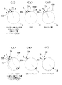
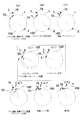
図9は、記録ドラム1への刷版100の装着作業を説明する説明図である。この図では、各段階における記録ドラム1の角度位置と関連部品の位置とが概略的に示されている。図10は、記録ドラム1からの刷版100の取り外し作業を説明する説明図であり、図9と同様に、各段階における記録ドラム1の角度位置と関連部品の位置とが概略的に示されている。
FIG. 9 is an explanatory diagram for explaining the mounting operation of the
図11、図12は、記録ドラムの外周面にガイド部材13が設置されていない場合における刷版着脱作業を本実施の形態と比較するための比較例である。なお、図11および図12は本発明を構成するものではないので詳細な説明は省略する。
11 and 12 are comparative examples for comparing the plate attaching / detaching operation when the
図9を参照して、刷版装着作業では、最初に回転駆動装置4によって、記録ドラム1を正方向Aまたは逆方向−Aに回転させる。これにより駆動装置7の解除ピン78が記録ドラム1上の先端クランプ2に対向する。次に、回転駆動装置4はそのブレーキ機構により記録ドラム1の回転を禁止する。次に、クランプアーム駆動モータ50(図3参照)がクランプアーム6を回動する。これにより、解除ピン78が先端クランプ2の他方側部20bを押圧して先端クランプ2を開放する。これと同時に、スクイジー駆動モータ57(図4参照)がスクイジーローラ55を記録ドラム1に向けて移動させる。図9(a)はこの状態を示している。
Referring to FIG. 9, in the plate mounting operation, first, the
続いて搬送ユニット9の第1の搬送路91(図2参照)が未露光の刷版100を先端クランプ2に向けて送り出す。図9(b)は第1の搬送路91から送り出された刷版100の先端が先端クランプ2に到達した状態を示している。
Subsequently, the first transport path 91 (see FIG. 2) of the
刷版100の先端が記録ドラム1上の位置決めピン(不図示)によって位置決めされると、クランプアーム6が揺動して解除ピン78が後退する。これによって、先端クランプ2はそのスプリング25(図8参照)の反力により刷版100の先端を記録ドラム1の外周面との間に挟み込むように閉鎖する。図9(c)はこの先端クランプ2の閉鎖が完了した状態を示している。
When the front end of the
続いて記録ドラム1が正方向Aに回転し、記録ドラム1の外周面に刷版100が順次に巻き付けられていく。スクイジーローラ55はすでに記録ドラム1の外周面と接しており記録ドラム1の回転に従動して回転しつつ記録ドラム1の外周面に沿って移動する。
Subsequently, the
図9(d)は先端クランプ2がスクイジーローラ55に対向する角度位置まで記録ドラムが回転した状態を示している。本実施の形態の描画装置では、記録ドラム1の外周面にガイド部材13が設けられているのでスクイジーローラ55の移動経路が変更できる。このため、スクイジーローラ55はガイド部材13の傾斜面13aに沿って記録ドラム1から離れる方向に移動して先端クランプ2を乗り越えることができる。
FIG. 9D shows a state where the recording drum is rotated to an angular position where the
ガイド部材13が設置されていない場合を考える。この場合、比較例の図11(c’)(c’’)に示されているように、先端クランプ2がスクイジーローラ55を通過した時点で記録ドラム1の回転を停止して回転駆動機構4のブレーキをかける(c’)。その後、スクイジーローラ55を記録ドラム1に向けて移動させる(c’’)。その後、ブレーキを解除して記録ドラムの回転を再開させる、という一連の作業が別途必要になる。このため、比較例では本実施の形態の描画装置よりも刷版装着時間が長くなる。
Consider a case where the
図13は、刷版装着時におけるスクイジーローラ55のガイド部材13への乗り上げの様子を説明する説明図である。記録ドラム1の正方向Aの回転によってスクイジーローラ55は矢印E方向に回転しながら、位置a、b、c、d、eの順に記録ドラム1の外周面に沿って矢印F方向に移動していく。なお、図13中の一点鎖線55bはスクイジーローラ55の回転中心の軌跡を示している。
FIG. 13 is an explanatory diagram for explaining how the
先述したように、スクイジーローラ55の回転軸55aは、ばね66によって記録ドラム1に向けて付勢された状態で、揺動部材56の長孔64(図4参照)内に保持されている。このためスクイジーローラ55は、位置bから位置cへ、また位置dから位置eへ滑らかに、かつ記録ドラム1に対する押圧力を維持したまま移動することができる。
As described above, the
なお、ガイド部材13の傾斜面13aおよび13cの形状は、スクイジーローラ55が刷版100を傷つけることがないよう、以下の事情を考慮して決定される。
The shapes of the
スクイジーローラ55は記録ドラム1の回転に従動して回転するので、スクイジーローラ55の回転速度は当該ローラ55と記録ドラム1外周面との接点から記録ドラム1の回転中心までの距離の大きさに依存する。そのため、スクイジーローラ55がガイド部材13上に乗り上げた状態(図13のc、dの状態)では、スクイジーローラ55が記録ドラム1の外周面または刷版100に接している状態(同a,b,eの状態)よりも高速度で回転することになる。
Since the
したがって、スクイジーローラ55は位置dから位置eに移動する間に回転速度が徐々に落とされていく。傾斜面13cの傾斜角度が適切であれば、位置eに達した時点でスクイジーローラ55の回転速度は刷版100の移動速度と略同一になるまで低下する。この場合、刷版100がスクイジーローラ55との摩擦によって傷つけられることはない。しかし、傾斜面13cの傾斜角度が大きすぎると、スクイジーローラ55の慣性のために回転速度が速いままで位置eに達することになる。この場合、スクイジーローラ55の回転速度と刷版100の移動速度との差によって摩擦が生じ刷版100が傷つけられてしまう。
Accordingly, the rotational speed of the
しかし、傾斜面13cの傾斜角度が小さすぎると、スクイジーローラ55によって刷版100が押圧される部分が減少し、刷版100が記録ドラム1の外周面に十分に密着しなくなるという別の問題も生じる。
However, if the inclination angle of the
ガイド部材13の形状は上記した相反する事情を考慮して適切に決定される。発明者によると、傾斜面13a、13bを単純な直線と仮定したときにこれらの傾斜面が記録ドラム1の接線に対して約145度となるようにガイド部材13を製作すると良好な結果が得られた。
The shape of the
再び、図9に戻って、記録ドラム1の正方向Aの回転はスクイジーローラ55が先端クランプ2を乗り越えるときも中断することなく、刷版100の全長が搬送ユニット9から送り出されて刷版100の後端が記録ドラム1の外周面に到達する段階まで継続して行われる。このように、本実施の形態では、刷版100の先端が先端クランプ2によって固定されてから、刷版100の全長が記録ドラム1の外周面に到達するまで、記録ドラム1が途中でその回転を停止することがない。このため刷版100の装着を迅速に行うことができる。
Returning again to FIG. 9, the rotation of the
次に、クランプアーム6が揺動して、保持ピン76によって保持されていた後端クランプ3が記録ドラム1の外周面まで移動する。その後、係合部材がクランプ溝11に係合することで後端クランプ3が記録ドラム1の外周面に固定される。図9(e)はこの段階を示している。
Next, the
その後、スクイジーローラ55は記録ドラム1から離れる方向に移動する。図9(f)はこの段階を示している。
Thereafter, the
以上によって刷版100の記録ドラム1への装着が完了し、記録ヘッド8による刷版100への画像記録が開始される。
Thus, the mounting of the
次に、図10を参照しながら刷版100の取り外しを説明する。最初に、後端クランプ3が駆動バー60に対向する位置まで記録ドラム1を回転させ、次に回転駆動装置4のブレーキ機構により制動をかける(図10(a))。次にスクイジーローラ55を記録ドラム1に向けて移動させる(図10(b))。その後、駆動ピン75によって後端クランプ3のクランプ溝11への係合を解除するとともに、保持ピン76によって後端クランプ3を駆動装置7に保持させる。その後、クランプアーム6が記録ドラム1から離れる方向に揺動して後端クランプ3の取り外しが完了する。図10(c)はこの段階を示している。
Next, removal of the
その後、回転駆動装置4のブレーキ機構による制動を解除し、記録ドラム1の逆方向−Aの回転を開始する。記録ドラム1上の刷版100は装着時における後端を先頭にして搬送ユニットの第2の搬送路92に収納されていく。この排出作業はスクイジーローラ55によって刷版100を押圧した状態で行っているので、刷版100のテンションを適切な強度で維持することができる。
Thereafter, braking by the brake mechanism of the rotation driving device 4 is released, and the rotation of the
上記記録ドラム1の回転は先端クランプ2が解除ピン78に対向するまで、途中で中断することなく行われる。この回転中に、スクイジーローラ55のガイド部材13上への乗り上げが行われる。すなわち、スクイジーローラ55は、ガイド部材13の傾斜面13cからガイド部材13に乗り上げ、通過面13bを経由して傾斜面13aから記録ドラム1外周面に向けて移動する。
The
先端クランプ2近傍にガイド部材13が存在しない場合には、図12(c’)の比較例に示すように、まず先端クランプ2がスクイジーローラ55に接近した段階で記録ドラム1の回転を一旦停止し、制動をかける。次に、図12(c’’)に示すようにスクイジーローラ55を記録ドラム1から離脱させる。その上で、記録ドラム1の制動解除および回転再開を実行する。このように、先端クランプ2を乗り越えさせるための部材が存在しない場合には、図12(c’)(c’’)に示す工程が別途必要になる。その分、刷版100の排出に長い時間がかかることになる。
When the
本実施の形態に係る描画装置では、刷版の着脱の途中で記録ドラム1を停止させる回数が少なくて済むので刷版着脱時間を短縮することができる。これによって、前の刷版の画像記録完了から次の刷版の画像記録開始までの間隔も短縮される。この結果、描画装置の稼働率が向上し、描画装置の生産性(たとえば単位時間あたりの刷版の記録枚数)が改善する。
In the drawing apparatus according to the present embodiment, since the number of times of stopping the
再び図10に戻って、先端クランプ2が解除ピン78に対向する位置まで記録ドラム1が回転すると記録ドラム1の回転に制動がかけられ、次に先端クランプ2が解除ピン78によって開放される(図10(e))。続いて、搬送ユニット9の第2の搬送路92に配された図示しないニップローラによって刷版100の残余の部分が搬送ユニット9に向けて搬送される。これによって刷版100の記録ドラム1からの取り外しが完了する。
Returning to FIG. 10 again, when the
搬送ユニット9の第1の搬送路91に次の未露光刷版100が配置されている場合には直ちにその刷版100の装着作業が開始される。
When the next
このような描画装置による刷版の一連の処理は、主として、回転する記録ドラムの表面に刷版を装着する装着工程と、装着した刷版にレーザ光を照射する画像記録工程と、回転する記録ドラムの表面から刷版を取り外す取り外し工程と、を備える。本発明では、これらの工程のうち装着工程と取り外し工程に要する時間を短縮する効果を得ることができる。この実施の形態で説明した描画装置において、標準的な画像記録条件の下で、装着工程と取り外し工程に要する時間を実際にそれぞれ計測したところ、1枚の刷版について装着工程に要する時間を2秒、取り外し工程に要する時間を2秒、それぞれ短縮することができた。すなわち、1枚の刷版に対する一連の処理を、合計4秒短縮することができた。これを刷版処理枚数で評価すると、1台の描画装置につき1時間あたりの刷版処理枚数を約1枚増加させたこととなる。これは、本技術分野において処理効率の向上が大きな課題となっている近年の状況を考慮すれば、格別な時間的、経済的効果であるというべきである。また、本発明は、従来の描画装置に対してガイド部材(カム等の部品)を追加するとともに装置の動作を制御するソフトウエアを変更することにより、比較的低コストで実現することができ、上記の効果を得ることができる。 A series of processing of the printing plate by such a drawing apparatus mainly includes a mounting step of mounting the printing plate on the surface of the rotating recording drum, an image recording step of irradiating the mounted printing plate with laser light, and a rotating recording. Removing the plate from the surface of the drum. In this invention, the effect which shortens the time which an installation process and a removal process among these processes require can be acquired. In the drawing apparatus described in this embodiment, under the standard image recording conditions, the time required for the mounting process and the removal process was actually measured. Second, the time required for the removal process could be shortened by 2 seconds. That is, a series of processes for one printing plate could be shortened by a total of 4 seconds. When this is evaluated in terms of the number of plates processed, the number of plates processed per hour for each drawing apparatus is increased by about one. This should be an exceptional time and economic effect considering the recent situation where improvement of processing efficiency is a major issue in this technical field. Further, the present invention can be realized at a relatively low cost by adding a guide member (part such as a cam) to the conventional drawing apparatus and changing software for controlling the operation of the apparatus. The above effects can be obtained.
(変形例)
上記実施の形態の描画装置では、多サイズの刷版100を固定可能にするために後端クランプ3を記録ドラム1に対して着脱できるようにしている。しかし、多サイズ対応にするのでないならば後端クランプ3は必ずしも着脱可能でなくてもよい。この場合にも本発明を適用することができる。
(Modification)
In the drawing apparatus of the above embodiment, the
また、上記実施の形態の描画装置では、記録ドラム1に対する刷版100の供給路と排出路がともに重なった状態で記録ドラム1の上方に位置していたために供給時と排出時とで記録ドラム1の回転方向を異ならせる必要があった。しかし、刷版の供給路および排出路がこれとは異なる位置に配置される場合には、記録ドラム1は必ずしも正逆両方向に回転可能である必要はない。この場合にも本発明を適用することができる。
Further, in the drawing apparatus of the above embodiment, since the supply path and discharge path of the
上記実施の形態では、スクイジーローラ55の移動経路を変更するためにガイド部材13を配置した。しかし、スクイジーローラ55とは異なる別の部材の移動経路を変更するためにガイド部材を配置することもできる。たとえば、記録ドラム1または刷版100の外周面をクリーニングするクリーニングローラを単体のローラとして準備する描画装置を使用する場合には、このクリーニングローラが先端クランプ2および/または後端クランプ3を乗り越えるためのガイド部材を配置することもできる。この場合にも本発明の適用は可能である。
In the above embodiment, the
また、先端クランプ2や後端クランプ3のようなクランプ部材以外の構造物が記録ドラム1の外周面に設置される場合にも、これを回避するためのガイド部材を記録ドラム1に配置することもできる。この場合にも本発明の適用は可能である。
In addition, when a structure other than the clamp member such as the
さらに、上記実施の形態では、記録ドラム1の端面近傍に1つずつガイド部材13を配置したが、記録ドラム1が軸方向に長くなる場合などには、ガイド部材の数を増やすことも可能である。
Furthermore, in the above embodiment, the
上記実施の形態では記録ドラム1の外周面には刷版100は1枚しか巻装されなかったが、記録ドラム1の円周方向および/または軸方向に複数枚の刷版を巻装する場合であっても本発明の適用は可能である。
In the above embodiment, only one
なお、上記実施の形態では、先端クランプおよび後端クランプは複数に分割されていたが、単一の構造をとっていても同様の機能を果たすことができる。 In the above embodiment, the front end clamp and the rear end clamp are divided into a plurality of parts, but the same function can be achieved even if a single structure is adopted.
1 記録ドラム
2 先端クランプ
3 後端クランプ
4 回転駆動装置
5 クランプ駆動装置
6 クランプアーム
7 駆動装置
8 記録ヘッド
9 搬送ユニット
13 ガイド部材
13a 傾斜面
13b 通過面
13c 傾斜面
20 クランプ本体
20a 一方の側部
20b 他方の側部
53 スクイジー装置
54 粘着ローラ
55 スクイジーローラ
56 揺動部材
57 スクイジー駆動モータ
58 ネジ
59 回動軸
60 駆動バー
64 長孔
65 ベアリング
66 ばね
75 駆動ピン
76 保持ピン
78 解除ピン
100 刷版
DESCRIPTION OF
Claims (14)
前記ローラが前記記録ドラムの外周面に設置された構造物を回避できるように、前記ローラをその上に乗り上げさせて当該ローラの移動経路を変更するガイド部材を前記構造物の近傍位置に設置し、
前記ローラは前記駆動手段上で前記外周面に対する接離方向に関してスライド可能に保持されており、前記駆動手段は前記ローラを前記外周面に向けて付勢する付勢手段をさらに有し、
前記ガイド部材は、前記ローラを前記記録ドラムの外周面から離隔する方向に乗り上げさせる第1傾斜面と、前記ローラをして前記構造物の上方を通過させる通過面と、前記ローラを前記記録ドラムの外周面に接近する方向に移動させる第2傾斜面とを有することを特徴とする描画装置。 A recording drum that rotates in a predetermined direction around an axis while mounting a sheet-shaped recording material, and moves relative to the outer peripheral surface along the outer peripheral surface of the recording drum, thereby moving the recording material to the outer peripheral surface. A roller that presses toward the recording drum, a driving unit that moves the roller in a direction toward and away from the recording drum, and a recording material mounted on the recording drum by irradiating the recording material with a desired laser beam. A drawing device having a recording head for forming an image,
In order to avoid the structure where the roller is installed on the outer peripheral surface of the recording drum, a guide member that changes the moving path of the roller by riding on the roller is installed near the structure. ,
The roller is slidably held on the driving means with respect to the contact / separation direction with respect to the outer peripheral surface, and the driving means further includes biasing means for biasing the roller toward the outer peripheral surface,
The guide member includes a first inclined surface that causes the roller to ride up in a direction away from the outer peripheral surface of the recording drum, a passage surface that allows the roller to pass above the structure, and the roller to the recording drum. And a second inclined surface that is moved in a direction approaching the outer peripheral surface of the drawing device.
前記ローラの前記回転軸方向の長さは、前記一対のガイド部材の間隔以上の長さであることを特徴とする請求項2記載の描画装置。The drawing apparatus according to claim 2, wherein a length of the roller in the rotation axis direction is equal to or longer than a distance between the pair of guide members.
前記クランプ部材の高さよりも高いことを特徴とする請求項3記載の描画装置。The drawing apparatus according to claim 3, wherein the drawing apparatus is higher than a height of the clamp member.
前記記録ドラムが前記逆方向に回転するときには、When the recording drum rotates in the reverse direction,
前記第2傾斜面は、前記ローラを前記記録ドラムの外周面から離隔する方向に乗り上げさせる傾斜面として、前記第1傾斜面は、前記ローラを前記記録ドラムの外周面に接近する方向に移動させる傾斜面として、それぞれ機能することを特徴とする請求項5記載の描画装置。The second inclined surface is an inclined surface that causes the roller to run up in a direction away from the outer peripheral surface of the recording drum, and the first inclined surface moves the roller in a direction closer to the outer peripheral surface of the recording drum. 6. The drawing apparatus according to claim 5, wherein each of the drawing apparatuses functions as an inclined surface.
前記記録材料が装着される円筒状の外周面を有しており、当該円筒の軸を中心に回転する記録ドラムと、A recording drum having a cylindrical outer peripheral surface on which the recording material is mounted, and rotating about the axis of the cylinder;
前記記録材料を前記記録ドラムに送り出す搬送機構と、A transport mechanism for feeding the recording material to the recording drum;
閉鎖方向に付勢されたクランプ本体を有する先端クランプと、A tip clamp having a clamp body biased in the closing direction;
前記先端クランプを押圧して前記クランプ本体を開放させる解除機構と、A release mechanism for pressing the tip clamp to open the clamp body;
前記記録ドラムの回転方向に関して前記解除機構よりも下流側に配設され、前記外周面に沿いながら当該外周面に対して相対的に移動するローラと、A roller disposed downstream of the release mechanism with respect to the rotation direction of the recording drum and moving relative to the outer peripheral surface along the outer peripheral surface;
前記ローラが前記先端クランプを回避できるように、前記ローラをその上に乗り上げさせて当該ローラの移動経路を変更する、前記先端クランプの近傍位置に設置されたガイド部材と、を有し、A guide member installed in the vicinity of the tip clamp, which changes the movement path of the roller by riding on the roller so that the roller can avoid the tip clamp,
前記外周面に記録材料を装着する際には、When mounting the recording material on the outer peripheral surface,
前記先端クランプが前記搬送機構に対向する位置まで前記記録ドラムを回転させ、Rotate the recording drum to a position where the tip clamp faces the transport mechanism,
前記解除機構によって先端クランプのクランプ本体を開放させ、The clamp body of the tip clamp is opened by the release mechanism,
前記搬送機構から前記記録材料を前記記録ドラムに向けて送り出し、Sending the recording material from the transport mechanism toward the recording drum;
前記クランプ本体によって前記記録材料の先端を固定した後、当該記録材料のほぼ全長が前記外周面に到達するまで、前記ローラによって前記記録材料の押圧を行いながら前記記録ドラムを停止させずに回転させ、After fixing the leading end of the recording material by the clamp body, the recording drum is rotated without stopping while pressing the recording material by the roller until almost the entire length of the recording material reaches the outer peripheral surface. ,
前記ローラは所定の駆動手段上で前記外周面に対する接離方向に関してスライド可能に保持されており、前記駆動手段は前記ローラを前記外周面に向けて付勢する付勢手段をさらに有し、The roller is held so as to be slidable in a contact / separation direction with respect to the outer peripheral surface on a predetermined driving unit, and the driving unit further includes a biasing unit that biases the roller toward the outer peripheral surface,
前記ガイド部材は、前記ローラを前記記録ドラムの外周面から離隔する方向に乗り上げさせる第1傾斜面と、前記ローラをして前記先端クランプの上方を通過させる通過面と、前記ローラを前記記録ドラムの外周面に接近する方向に移動させる第2傾斜面とを有することを特徴とする描画装置。The guide member includes a first inclined surface that causes the roller to run up in a direction away from the outer peripheral surface of the recording drum, a passage surface that allows the roller to pass over the tip clamp, and the roller to the recording drum. And a second inclined surface that is moved in a direction approaching the outer peripheral surface of the drawing device.
前記記録材料が装着される円筒状の外周面を有しており、当該円筒の軸を中心に所定の回転方向に回転する記録ドラムと、A recording drum having a cylindrical outer peripheral surface on which the recording material is mounted, and rotating in a predetermined rotation direction about the axis of the cylinder;
前記記録材料を前記記録ドラムから搬出する搬送路と、A conveyance path for carrying out the recording material from the recording drum;
前記記録材料の前記回転方向上流側の一端を前記記録ドラムの外周面に固定する先端クランプと、A tip clamp that fixes one end of the recording material upstream in the rotational direction to the outer peripheral surface of the recording drum;
前記記録材料の他端を前記記録ドラムの外周面に固定する後端クランプと、A rear end clamp for fixing the other end of the recording material to the outer peripheral surface of the recording drum;
前記記録ドラムに対する前記後端クランプの着脱を行う着脱手段と、An attachment / detachment means for attaching / detaching the rear end clamp to / from the recording drum;
前記着脱手段よりも前記回転方向上流側に配設され、前記外周面に沿いながら当該外周面に対して相対的に移動するローラと、A roller that is disposed on the upstream side in the rotational direction from the attaching / detaching means and moves relative to the outer peripheral surface along the outer peripheral surface;
前記ローラが前記先端クランプを回避できるように、前記ローラをその上に乗り上げさせて当該ローラの移動経路を変更する、前記先端クランプの近傍位置に設置されたガイド部材と、を有し、A guide member installed in the vicinity of the tip clamp, which changes the movement path of the roller by riding on the roller so that the roller can avoid the tip clamp,
前記外周面から記録材料を取り外す際には、When removing the recording material from the outer peripheral surface,
前記後端クランプが前記着脱手段に対向する位置まで前記記録ドラムを回転させ、Rotate the recording drum to a position where the rear end clamp faces the attaching / detaching means,
前記着脱手段によって前記記録ドラムから前記後端クランプを取り外し、Removing the rear end clamp from the recording drum by the attaching / detaching means;
前記ローラによって前記記録材料の押圧を行いながら前記記録ドラムを回転させて、前記記録材料を前記搬送路へ収納させ、The recording drum is rotated while pressing the recording material by the roller, and the recording material is stored in the conveyance path,
前記ローラは所定の駆動手段上で前記外周面に対する接離方向に関してスライド可能に保持されており、前記駆動手段は前記ローラを前記外周面に向けて付勢する付勢手段をさらに有し、The roller is held so as to be slidable in a contact / separation direction with respect to the outer peripheral surface on a predetermined driving unit, and the driving unit further includes a biasing unit that biases the roller toward the outer peripheral surface,
前記ガイド部材は、前記ローラを前記記録ドラムの外周面から離隔する方向に乗り上げさせる第1傾斜面と、前記ローラをして前記先端クランプの上方を通過させる通過面と、前記ローラを前記記録ドラムの外周面に接近する方向に移動させる第2傾斜面とを有することを特徴とする描画装置。The guide member includes a first inclined surface that causes the roller to run up in a direction away from the outer peripheral surface of the recording drum, a passage surface that allows the roller to pass over the tip clamp, and the roller to the recording drum. And a second inclined surface that is moved in a direction approaching the outer peripheral surface of the drawing device.
前記記録材料へレーザ光を照射する画像記録工程と、An image recording step of irradiating the recording material with laser light;
前記ローラにより、前記記録材料の一部分を回転する前記記録ドラムの外周面に押圧しつつ、前記記録材料を前記記録ドラムから取り外す取り外し工程と、A step of removing the recording material from the recording drum while pressing the outer peripheral surface of the recording drum rotating a part of the recording material by the roller;
を備え、With
前記装着工程および前記取り外し工程において、前記ローラを前記記録ドラムの外周面に設置された構造物の近傍位置に設置したガイド部材に乗り上げさせることにより、前記構造物を回避させるガイド工程を、それぞれ含み、The mounting step and the removing step each include a guide step for avoiding the structure by riding the roller on a guide member installed in the vicinity of the structure installed on the outer peripheral surface of the recording drum. ,
前記ローラは前記記録ドラムの外周面に向けて付勢されており、The roller is biased toward the outer peripheral surface of the recording drum;
前記ガイド工程は、The guide process includes
前記ローラを前記記録ドラムの外周面から離隔する方向に乗り上げさせる第1工程と、A first step of riding the roller in a direction away from the outer peripheral surface of the recording drum;
前記ローラをして前記構造物の上方を通過させる第2工程と、A second step of allowing the roller to pass over the structure;
前記ローラを前記記録ドラムの外周面に接近する方向に移動させる第3工程とA third step of moving the roller in a direction approaching the outer peripheral surface of the recording drum;
を含むことを特徴とする描画方法。The drawing method characterized by including.
前記記録材料を前記記録ドラムに送る第4工程と、A fourth step of sending the recording material to the recording drum;
前記記録材料の一端を前記記録ドラムの外周面に固定する第5工程と、A fifth step of fixing one end of the recording material to the outer peripheral surface of the recording drum;
前記記録材料のほぼ全長が前記記録ドラムの外周面に到達するまで前記ローラによる押圧を行いながら前記記録ドラムの回転を継続させる第6工程とA sixth step of continuing the rotation of the recording drum while pressing with the roller until the substantially entire length of the recording material reaches the outer peripheral surface of the recording drum;
をさらに含むことを特徴とする請求項12記載の描画方法。The drawing method according to claim 12, further comprising:
前記記録材料の他端の前記記録ドラムの外周面への固定を解除する第7工程と、A seventh step of releasing fixation of the other end of the recording material to the outer peripheral surface of the recording drum;
前記ローラによる前記記録材料の押圧を行いながら前記記録ドラムを回転させることにより前記記録材料を排出する第8工程と、An eighth step of discharging the recording material by rotating the recording drum while pressing the recording material by the roller;
をさらに含むことを特徴とする請求項13記載の描画方法。The drawing method according to claim 13, further comprising:
Priority Applications (2)
| Application Number | Priority Date | Filing Date | Title |
|---|---|---|---|
| JP2003407005A JP4331577B2 (en) | 2003-02-03 | 2003-12-05 | Drawing apparatus and drawing method |
| US10/769,981 US7121202B2 (en) | 2003-02-03 | 2004-02-03 | Imaging apparatus and imaging method to increase efficiency of mounting/demounting of a recording material to/from a recording drum |
Applications Claiming Priority (2)
| Application Number | Priority Date | Filing Date | Title |
|---|---|---|---|
| JP2003025950 | 2003-02-03 | ||
| JP2003407005A JP4331577B2 (en) | 2003-02-03 | 2003-12-05 | Drawing apparatus and drawing method |
Publications (2)
| Publication Number | Publication Date |
|---|---|
| JP2004258619A JP2004258619A (en) | 2004-09-16 |
| JP4331577B2 true JP4331577B2 (en) | 2009-09-16 |
Family
ID=33133615
Family Applications (1)
| Application Number | Title | Priority Date | Filing Date |
|---|---|---|---|
| JP2003407005A Expired - Fee Related JP4331577B2 (en) | 2003-02-03 | 2003-12-05 | Drawing apparatus and drawing method |
Country Status (2)
| Country | Link |
|---|---|
| US (1) | US7121202B2 (en) |
| JP (1) | JP4331577B2 (en) |
Families Citing this family (4)
| Publication number | Priority date | Publication date | Assignee | Title |
|---|---|---|---|---|
| JP2005316116A (en) * | 2004-04-28 | 2005-11-10 | Dainippon Screen Mfg Co Ltd | Apparatus and method for scanning outer surface of cylinder |
| ITMI20112269A1 (en) * | 2011-12-15 | 2013-06-16 | Pirelli | METHOD FOR CHECKING THE DEPOSITION OF A LAYER OF SEALING POLYMERIC MATERIAL ON A FORMING DRUM AND PROCESS FOR PRODUCING SELF-SEALING TIRES FOR VEHICLE WHEELS |
| WO2013157356A1 (en) * | 2012-04-19 | 2013-10-24 | 株式会社ニコン | Mask unit and substrate processing device |
| KR102396761B1 (en) * | 2015-04-24 | 2022-05-11 | 삼성디스플레이 주식회사 | display apparatus |
Family Cites Families (4)
| Publication number | Priority date | Publication date | Assignee | Title |
|---|---|---|---|---|
| JP2694313B2 (en) | 1992-10-19 | 1997-12-24 | セイコーインスツルメンツ株式会社 | Electronic equipment using ultrasonic motor |
| JP3142467B2 (en) * | 1995-10-12 | 2001-03-07 | アルプス電気株式会社 | Thermal transfer printer |
| JP3645131B2 (en) | 1998-08-04 | 2005-05-11 | 大日本スクリーン製造株式会社 | Drawing device |
| JP3708716B2 (en) * | 1998-08-04 | 2005-10-19 | 大日本スクリーン製造株式会社 | Drawing device |
-
2003
- 2003-12-05 JP JP2003407005A patent/JP4331577B2/en not_active Expired - Fee Related
-
2004
- 2004-02-03 US US10/769,981 patent/US7121202B2/en active Active
Also Published As
| Publication number | Publication date |
|---|---|
| JP2004258619A (en) | 2004-09-16 |
| US7121202B2 (en) | 2006-10-17 |
| US20040227912A1 (en) | 2004-11-18 |
Similar Documents
| Publication | Publication Date | Title |
|---|---|---|
| JP4025105B2 (en) | Sheet material fixing device | |
| JPH08108525A (en) | Method and apparatus for automatically replacing printing plate of rotary press | |
| JP4331577B2 (en) | Drawing apparatus and drawing method | |
| JP2005280820A (en) | Label sticking apparatus | |
| US6746010B2 (en) | Apparatus for conveying sheet-like recording material | |
| JP2002236374A (en) | Rotating body | |
| WO2012010076A1 (en) | An image generating apparatus, processing box matched thereto and method for firmly positioning both | |
| JP2004175501A (en) | Image exposing device | |
| JP2001047604A (en) | Automatic press plate fitting and removing device | |
| JP4604266B2 (en) | Plate changing apparatus and plate changing method | |
| JP2003091073A (en) | Sheet material holding apparatus | |
| JP2005280821A (en) | Label sticking apparatus | |
| JP3980275B2 (en) | Apparatus for attaching / detaching sheet body to / from rotating drum, rotating drum type exposure apparatus / method for sheet-like photosensitive material | |
| JP4340049B2 (en) | Drawing device | |
| US6786154B2 (en) | Mechanism for correcting unbalance of a rotor | |
| JP3795638B2 (en) | Plate making and conveying device | |
| JP4436051B2 (en) | Plate vise drive device and drive method for printing press | |
| JP2004102042A (en) | Sheet material fixing device | |
| JP2003280210A (en) | Sheet material holding device | |
| JP2002258491A (en) | Image recording device and its plate fitting method | |
| JP4308443B2 (en) | Sheet-like member positioning apparatus and image recording apparatus | |
| JP2003095476A (en) | Sheet material carrying device | |
| JP2003095491A (en) | Sheet material positioning device | |
| JP2002268233A (en) | Sheet-like member holding method | |
| JP2004315134A (en) | Sheet member holding device |
Legal Events
| Date | Code | Title | Description |
|---|---|---|---|
| A621 | Written request for application examination |
Free format text: JAPANESE INTERMEDIATE CODE: A621 Effective date: 20051110 |
|
| A977 | Report on retrieval |
Free format text: JAPANESE INTERMEDIATE CODE: A971007 Effective date: 20081127 |
|
| A131 | Notification of reasons for refusal |
Free format text: JAPANESE INTERMEDIATE CODE: A131 Effective date: 20081202 |
|
| A521 | Request for written amendment filed |
Free format text: JAPANESE INTERMEDIATE CODE: A523 Effective date: 20090130 |
|
| RD04 | Notification of resignation of power of attorney |
Free format text: JAPANESE INTERMEDIATE CODE: A7424 Effective date: 20090130 |
|
| TRDD | Decision of grant or rejection written | ||
| A01 | Written decision to grant a patent or to grant a registration (utility model) |
Free format text: JAPANESE INTERMEDIATE CODE: A01 Effective date: 20090616 |
|
| A01 | Written decision to grant a patent or to grant a registration (utility model) |
Free format text: JAPANESE INTERMEDIATE CODE: A01 |
|
| A61 | First payment of annual fees (during grant procedure) |
Free format text: JAPANESE INTERMEDIATE CODE: A61 Effective date: 20090618 |
|
| R150 | Certificate of patent or registration of utility model |
Free format text: JAPANESE INTERMEDIATE CODE: R150 Ref document number: 4331577 Country of ref document: JP Free format text: JAPANESE INTERMEDIATE CODE: R150 |
|
| FPAY | Renewal fee payment (event date is renewal date of database) |
Free format text: PAYMENT UNTIL: 20120626 Year of fee payment: 3 |
|
| FPAY | Renewal fee payment (event date is renewal date of database) |
Free format text: PAYMENT UNTIL: 20120626 Year of fee payment: 3 |
|
| FPAY | Renewal fee payment (event date is renewal date of database) |
Free format text: PAYMENT UNTIL: 20120626 Year of fee payment: 3 |
|
| FPAY | Renewal fee payment (event date is renewal date of database) |
Free format text: PAYMENT UNTIL: 20120626 Year of fee payment: 3 |
|
| FPAY | Renewal fee payment (event date is renewal date of database) |
Free format text: PAYMENT UNTIL: 20130626 Year of fee payment: 4 |
|
| R250 | Receipt of annual fees |
Free format text: JAPANESE INTERMEDIATE CODE: R250 |
|
| R250 | Receipt of annual fees |
Free format text: JAPANESE INTERMEDIATE CODE: R250 |
|
| R250 | Receipt of annual fees |
Free format text: JAPANESE INTERMEDIATE CODE: R250 |
|
| S533 | Written request for registration of change of name |
Free format text: JAPANESE INTERMEDIATE CODE: R313533 |
|
| R350 | Written notification of registration of transfer |
Free format text: JAPANESE INTERMEDIATE CODE: R350 |
|
| R250 | Receipt of annual fees |
Free format text: JAPANESE INTERMEDIATE CODE: R250 |
|
| R250 | Receipt of annual fees |
Free format text: JAPANESE INTERMEDIATE CODE: R250 |
|
| R250 | Receipt of annual fees |
Free format text: JAPANESE INTERMEDIATE CODE: R250 |
|
| R250 | Receipt of annual fees |
Free format text: JAPANESE INTERMEDIATE CODE: R250 |
|
| R250 | Receipt of annual fees |
Free format text: JAPANESE INTERMEDIATE CODE: R250 |
|
| R250 | Receipt of annual fees |
Free format text: JAPANESE INTERMEDIATE CODE: R250 |
|
| R250 | Receipt of annual fees |
Free format text: JAPANESE INTERMEDIATE CODE: R250 |
|
| LAPS | Cancellation because of no payment of annual fees |