JP4331441B2 - Plain bearings and rotating machinery - Google Patents
Plain bearings and rotating machinery Download PDFInfo
- Publication number
- JP4331441B2 JP4331441B2 JP2002158161A JP2002158161A JP4331441B2 JP 4331441 B2 JP4331441 B2 JP 4331441B2 JP 2002158161 A JP2002158161 A JP 2002158161A JP 2002158161 A JP2002158161 A JP 2002158161A JP 4331441 B2 JP4331441 B2 JP 4331441B2
- Authority
- JP
- Japan
- Prior art keywords
- fibers
- sic
- fiber
- silicon carbide
- bearing
- Prior art date
- Legal status (The legal status is an assumption and is not a legal conclusion. Google has not performed a legal analysis and makes no representation as to the accuracy of the status listed.)
- Expired - Lifetime
Links
Images


Description
【0001】
【発明の属する技術分野】
本発明は、耐摺動性と耐摩耗性があり且つ摩擦係数を低くすることができる滑り軸受及び回転機械に関するものである。
【0002】
【従来の技術】
従来、遠心式ポンプ等の回転機械では、ポンプケーシング等の静止体に対してポンプ軸等の回転体を保持するために滑り軸受が使用される場合がある。この種の滑り軸受の材質は、簡便さより、通常、ゴム製の水潤滑軸受を使用することが多い。しかしながらゴム製の水潤滑軸受は、運転中に異物が混入した場合に摩耗を生じ易い。また運転開始時に潤滑水を供給しなければならないので、無注水で運転開始した後に揚水する水で潤滑するタイプの滑り軸受としては使用できない。
【0003】
一方無注水起動ができ、また水中での耐食性及び耐摩耗性を上げるためには、セラミック等、高硬度材料を使用すればよいが、この種の材質は靭性が低くて割れ易く、滑り軸受等の構造部品としては取り扱いが困難であった。
【0004】
そこで靭性を高めるために、セラミック繊維を成形することで構成される滑り軸受等の構造部品もあるが、その場合でもセラミック材料は摩擦係数が高いので、摺動時の発熱・冷却の繰り返しで割れが発生する恐れがあった。
【0005】
【発明が解決しようとする課題】
本発明は上述の点に鑑みてなされたものでありその目的は、耐摺動性及び耐摩耗性を上げることができ、靭性が高く、さらに摩擦係数も低くできる滑り軸受及び回転機械を提供することにある。
【0006】
【課題を解決するための手段】
本願発明は、前記セラミック繊維に炭素繊維を混紡することで、セラミックの特性(摩耗しにくいが摩擦係数大)と炭素の特性(摩耗するが摩擦係数小)とをバランス良く取って所定の硬度と摺動性を得るようにするとともに摩擦係数を小さくし、繊維とすることで靭性も向上させるようにした。
【0007】
即ち本願の請求項1にかかる発明は、連続単繊維を寄せ集めた炭化ケイ素(SiC)繊維と連続単繊維を寄せ集めた炭素繊維とをより合わせ且つこれら炭化ケイ素(SiC)繊維と炭素繊維全体に対する炭化ケイ素(SiC)繊維の混合割合を10〜80体積%、炭素繊維の混合割合を20〜90体積%としてなる複合糸を、織物、編物、組紐、或いはフィラメントワインディングに加工し、さらに反応ガス(CH 3 SiCl 3 −H 2 )を用いてその空隙に炭化ケイ素(SiC)を充填して構成した繊維強化セラミック(CFCC)からなる繊維強化構造体を用いて作製したことを特徴とする滑り軸受である。
糸とするためには炭化ケイ素(SiC)繊維と炭素繊維は何れも連続単繊維(Continuous Fiber)を寄せ集めたものであることが望ましい。ここで連続単繊維とは、繊維材料の最小単位であり、引き伸ばしたり、撚りをかけたりすることで形成される基礎の単位であり、単独では使用されず、寄せ集めて十分な強度と柔軟性を持った糸として使用される。
【0008】
繊維を用いた繊維強化構造体は、靭性があり、割れが生じにくい。特に破壊靭性を高くできるので、この繊維強化構造体を滑り軸受に用いることで異物を噛み込んでも欠ける恐れがなくなる。
【0009】
一方空隙にセラミックを充填した場合は、繊維強化セラミック(CFCC:Continuous Fiber Ceramic Composite)になり、空隙に金属を充填(含浸)した場合は金属マトリックス繊維強化材料(MMCs)になる。何れの材料を充填した場合も、耐摩耗性が向上するが、セラミックを充填した場合に最も耐摩耗性が向上する。一方金属は腐食する恐れがあるが、セラミックは腐食しない。
【0010】
織物、編物、組紐には、平面状に織っていく平織り等の二次元のものと、立体状に織っていく三次元のものとがある。二次元のものとしては、例えば図1に示すように糸100を平面状(X−Y軸方向)のみに織っていくものがある。三次元のものとしては、例えば図2(a)に示すように糸100をX−Y−Z軸方向に織っていくものや、円筒状であれば例えば図2(b)に示すように糸100を円周−軸−半径方向に織っていくものがある。また織物は例えば図3(a)に示すようにたて糸101とよこ糸103とをシャトル105等によって織って構成されるものであり、編物は例えば図3(b)に示すように糸107を編み機109等によって編んで構成されるものであり、組紐は例えば図3(c)に示すように糸111を紐状に組み合わせて構成されるものである。またフィラメントワインディングとは、例えば図3(d)に示すように予め表面に樹脂を付着した複合紡績糸115を加圧ローラ117で加圧しながら心棒120に巻きつけていくことで所定の形状を形成するものである。
【0011】
二次元の織物等を用いて円筒状の軸受を構成する場合、平板状の織物等を円筒状に複数回巻き回して軸受を構成することとなるので、内部で生じた熱の伝導が半径方向よりも円周方向に伝達し易くなる。このため熱の外部への伝達が効果的に行えない。一方三次元の織物等を用いて円筒状の軸受を構成する場合は、内部で生じた熱は半径方向にも円周方向と同様に伝導していくので外部への熱の伝達が容易に行え、好適である。
【0012】
複合紡績糸を織物、編物、組紐、或いはフィラメントワインディングに加工したものの空隙に、セラミックを含浸して繊維強化セラミックを得る方法としては、CVI(Chemical Vapor Infiltration)、CVD(Chemical Vapor Deposition)、RS(Reaction Sintering)、溶浸直接金属酸化法(Directed Oxidation(Lanxide) Process)、PIP(Polymer Infiltration and Pyrolysis)、MI(Melt Infiltration)、ゾル・ゲル法(Sol-Gel Techniques)、HIP(Hot Isostatic Processing)法等の、従来ある各種セラミック充填方法がある。セラミックの材質としては、炭化ケイ素(SiC)を用いる。
【0015】
この滑り軸受は、各種回転機械の回転軸の軸受けとして利用でき、耐摺動性、耐摩耗性に優れ且つ低摩擦係数なので、例えば水潤滑軸受に用いて好適である。特にこの滑り軸受を、無注水で運転開始した後に自己が揚水する水で潤滑を開始する構造のポンプ等の回転機械用の滑り軸受に用いたとしても、低摩擦係数のため水潤滑が開始されるまでの摺動による発熱量が小さく割れが生じることはなく、その使用に耐えられる。
【0016】
本願の請求項2にかかる発明は、請求項1記載の滑り軸受を組み込んだことを特徴とする回転機械である。
【0017】
【発明の実施の形態】
以下、本発明の実施の形態を図面を参照して詳細に説明する。
図4乃至図8は本発明を用いて水潤滑軸受を作製する手順の一例を示す図である。図4は複合糸30の製造装置を示す図である。同図に示すように複合糸30を製造するには、まずアクリル繊維(PAN、ポリアクリロニトリル)10をボビン11から引き出し、熱硬化装置13で200〜300℃に加熱して硬化させ、次に炭化装置15で高熱により炭化し、さらに黒鉛化装置17で高熱により黒鉛化し、所望の炭素繊維16を得る。一方SiC原料18を糸状に引き伸ばして加熱装置19で焼成し、次に安定化装置21で安定化処理を行い、さらに焼結装置23で焼結化し、所望のSiC繊維24を得る。そしてこれら炭素繊維16とSiC繊維24とを任意の割合でより合わせたものを表面処理装置25でシラン系溶剤に通してエポキシ樹脂が付着し易い状態とし、次にサイジング処理装置27でエポキシ樹脂を付着させた後、ボビン29に巻き取る。なお付着させたエポキシ樹脂は、以下の織物等を加工する工程中の加熱によって揮発する。
【0018】
図5は以上のようにして製造した複合糸30の要部拡大図である。同図に示すように複合糸30は、炭素繊維16とSiC繊維24とが絡み合って構成されている。この実施形態では複合糸30の直径は約200μmである。
【0019】
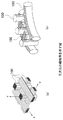
以上のようにして作製された複合糸30をこの実施形態においては、図6に示すように平織りして二次元の織物35とし、これを図7に示すように円筒状に巻き回して滑り軸受の形状の成形品40とする。次に図8に示すようにこの成形品40をCVI装置50の成形品収納室55内に収納する。ここでCVI装置50は、円筒状のヒータ51の外周を黒鉛製の容器53で囲むことでリング状の成形品収納室55を設けており、ヒータ51によって成形品収納室55内を加熱(加熱温度1400℃)しながら容器53の外周に設けた反応ガス入口57から反応ガス(CH3SiCl3−H2)を導入して成形品40を通した後に容器53の内周側に設けた反応ガス出口59から排出する。これによって成形品40の表面にSiCが析出し、成形品40の空隙にSiCが充填され、繊維強化構造体として繊維強化セラミック(CFCC)製の滑り軸受が完成する。
【0020】
以下に示す表1は以上のようにして製造される円筒状の滑り軸受のSiC繊維と炭素繊維の割合を変化させたときの各種機械的性質を測定した測定結果を示す表である。
【表1】

表1において空隙に充填するセラミック(基材:SiC)に対してSiC繊維と炭素繊維を合わせた繊維の比率を40%(基材60%)で一定にした上で、SiC繊維と炭素繊維の割合(体積%)を変化させてそれぞれの場合の各種機械的性質を測定した。その結果、繊維としてSiC繊維だけを用いた場合は摩擦係数が大きく(0.73〜0.55)、このSiC繊維に炭素繊維を少しだけでも(20%)混合すると摩擦係数が急激に低下し(0.23〜0.39)、さらに炭素繊維を増やしても摩擦係数はそれほど変化しない。一方炭素繊維だけを用いた場合は比摩耗量が大きく(7.2×10⁻⁸)、SiC繊維の混合量を増やしていくことで比摩耗量は指数関数的に大きく減少していく。これらのことから少なくとも炭素繊維の混合割合を20%以上にすることで摩擦係数は大きく低下し、また少なくともSiC繊維の混合量を10%以上にすることでSiC繊維を全く混合しない場合に比べて比摩耗量が大きく減少することがわかった。
【0022】
図9は本発明にかかる滑り軸受を用いて構成したポンプ60の一例を示す概略断面図である。同図に示すポンプ60は、ポンプケーシング61内にポンプ軸63を収納するとともにポンプ軸63の下端に羽根車65を取り付け、ポンプ軸63のポンプケーシング61から上部に突出した部分を図示しない駆動手段によって回転駆動して羽根車65を回転し、ポンプケーシング61の吸込口67から吐出口69に向けて水を揚水していくものである。そしてポンプ軸63を支持する滑り軸受71,73として本発明にかかる滑り軸受を用いている。これら滑り軸受71,73は揚水する水によって水潤滑される水潤滑軸受であり、運転開始時には滑り軸受71,73を潤滑する水は供給されていないが、本発明の滑り軸受71,73は摩擦係数が小さいので発熱量が少なく、割れ等の問題が発生しない。
【0023】
以上本発明の実施形態を説明したが、本発明は上記実施形態に限定されるものではなく、特許請求の範囲、及び明細書と図面に記載された技術的思想の範囲内において種々の変形が可能である。なお直接明細書及び図面に記載がない何れの形状や構造や材質であっても、本願発明の作用・効果を奏する以上、本願発明の技術的思想の範囲内である。例えば上記実施形態では滑り軸受を適用する回転機械としてポンプを示したが、タービン、コンプレッサー、ブロワ等の他の各種回転機械にも適用できる。
【0024】
【発明の効果】
以上詳細に説明したように本発明によれば、炭化ケイ素(SiC)繊維と炭素繊維とをより合わせてなる複合糸を用いたので、耐摺動性と耐摩耗性と靭性と耐食性が高く且つ低摩擦係数を有する滑り軸受が得られ、またこの滑り軸受は低摩擦係数なのでこれを回転機械に用いて好適であり、特にポンプに用いた場合は無注水起動が容易に行える。
【図面の簡単な説明】
【図1】二次元の織物等を示す要部拡大図である。
【図2】三次元の織物等を示す要部拡大図である。
【図3】織物と編物と組紐とフィラメントワインディングの例を示す要部拡大図である。
【図4】 複合糸30の製造装置を示す図である。
【図5】 複合糸30の要部拡大図である。
【図6】 複合糸30を平織りして作製した織物35を示す図である。
【図7】織物35を円筒状に巻き回した成形品40を示す図である。
【図8】CVI装置50によって成形品40にCVI処理を行う方法を示す図である。
【図9】本発明の滑り軸受71,73を適用したポンプ60の一例を示す図である。
【符号の説明】
10 アクリル繊維
11 ボビン
13 熱硬化装置
15 炭化装置
16 炭素繊維
17 黒鉛化装置
19 加熱装置
21 安定化装置
23 焼結装置
24 SiC繊維
25 表面処理装置
27 サイジング処理装置
30 複合糸
39 ボビン
35 織物
40 成形品
50 CVI装置
51 ヒータ
53 容器
55 成形品収納室
57 反応ガス入口
59 反応ガス出口
60 ポンプ
61 ポンプケーシング
63 ポンプ軸
65 羽根車
67 吸込口
69 吐出口
71,73 軸受[0001]
BACKGROUND OF THE INVENTION
The present invention relates to the slip bearing and rotary machine that can be lowered and the friction coefficient has sliding resistance and abrasion resistance.
[0002]
[Prior art]
Conventionally, in a rotary machine such as a centrifugal pump, a sliding bearing may be used to hold a rotary body such as a pump shaft with respect to a stationary body such as a pump casing. As a material for this type of plain bearing, a rubber water-lubricated bearing is often used because of its simplicity. However, rubber water-lubricated bearings are subject to wear when foreign matter enters during operation. Also, since lubricating water must be supplied at the start of operation, it cannot be used as a type of plain bearing that is lubricated with water that is pumped after starting operation without water injection.
[0003]
On the other hand, high-hardness materials such as ceramics may be used in order to start water-free injection and increase corrosion resistance and wear resistance in water. However, this type of material has low toughness and is easy to crack, such as sliding bearings. It was difficult to handle as a structural part.
[0004]
In order to increase toughness, there are structural parts such as sliding bearings formed by molding ceramic fibers, but even in that case, the ceramic material has a high coefficient of friction, so it cracks due to repeated heating and cooling during sliding. There was a risk of occurrence.
[0005]
[Problems to be solved by the invention]
The present invention has been made in view of the above points and its object is able to increase the sliding resistance and abrasion resistance, high toughness, yet coefficient of friction to be Ru the slip bearing and rotary machines low It is to provide.
[0006]
[Means for Solving the Problems]
In the present invention, by blending carbon fiber with the ceramic fiber, the ceramic properties (hard to wear but large friction coefficient) and carbon properties (wear but small friction coefficient) are taken in a well-balanced state to obtain a predetermined hardness. In addition to obtaining slidability, the coefficient of friction was reduced and the toughness was improved by using fibers.
[0007]
That is, the invention according to claim 1 of the present application is a combination of silicon carbide (SiC) fibers gathered with continuous single fibers and carbon fibers gathered with continuous single fibers, and these silicon carbide (SiC) fibers and the entire carbon fibers. 10-80% by volume mixing ratio of silicon carbide (SiC) fibers to a composite yarn formed by 20 to 90% by volume mixing ratio of the carbon fiber, and processed woven, knitted, braid, or filament winding, further reaction A slip produced by using a fiber reinforced structure made of a fiber reinforced ceramic (CFCC) configured by filling silicon carbide (SiC) into the voids using a gas (CH 3 SiCl 3 —H 2 ). It is a bearing.
In order to obtain a yarn, it is desirable that both silicon carbide (SiC) fibers and carbon fibers are a collection of continuous single fibers. Here, continuous single fiber is the smallest unit of fiber material, it is a basic unit formed by stretching or twisting, and it is not used alone, but gathers and has enough strength and flexibility Used as a thread with
[0008]
Fiber-reinforced structure using textiles, there is toughness, cracking hardly occurs. Since especially high fracture toughness, a possibility is eliminated that lacks bite foreign matters in Rukoto using fiber-reinforced structure of this the sliding bearing.
[0009]
On the other hand, when the gap is filled with ceramic, it becomes a fiber reinforced ceramic (CFCC: Continuous Fiber Ceramic Composite), and when the gap is filled (impregnated) with metal, it becomes a metal matrix fiber reinforced material (MMCs). When any material is filled, the wear resistance is improved, but when the ceramic is filled, the wear resistance is most improved . Hand metals corrode, but the ceramic does not corrode.
[0010]
Woven fabrics, knitted fabrics, and braids include two-dimensional ones such as plain weaves that are woven in a flat shape, and three-dimensional ones that are woven three-dimensionally. As a two-dimensional one, for example, as shown in FIG. 1, there is one in which the
[0011]
When a cylindrical bearing is configured using a two-dimensional fabric or the like, a flat fabric or the like is wound into a cylindrical shape a plurality of times to configure the bearing, so that heat conduction generated inside is radial. It becomes easier to transmit in the circumferential direction. For this reason, heat cannot be effectively transmitted to the outside. On the other hand, when a cylindrical bearing is constructed using a three-dimensional fabric or the like, the heat generated inside is conducted in the radial direction in the same way as in the circumferential direction, so that heat can be transferred to the outside easily. Is preferable.
[0012]
As a method for obtaining a fiber reinforced ceramic by impregnating a ceramic into a void of a composite spun yarn processed into a woven fabric, a knitted fabric, a braid, or a filament winding, CVI (Chemical Vapor Infiltration), CVD (Chemical Vapor Deposition), RS ( Reaction Sintering), Directed Oxidation (Lanxide) Process, PIP (Polymer Infiltration and Pyrolysis), MI (Melt Infiltration), Sol-Gel Techniques, HIP (Hot Isostatic Processing) There are various conventional ceramic filling methods such as the method. Silicon carbide (SiC 3 ) is used as the ceramic material.
[0015]
Sliding bearing of this may be used as a bearing of various rotating machines of the rotary shaft, sliding resistance, so excellent and low coefficient of friction and wear resistance, it is suitable for use for example in water-lubricated bearings. In particular, even if this sliding bearing is used for a sliding bearing for a rotary machine such as a pump having a structure in which it starts to lubricate with water pumped by itself after starting operation without water injection, water lubrication is started due to a low friction coefficient. The amount of heat generated by sliding until the end is small, and cracking does not occur and it can be used.
[0016]
The invention according to
[0017]
DETAILED DESCRIPTION OF THE INVENTION
Hereinafter, embodiments of the present invention will be described in detail with reference to the drawings.
4 to 8 are views showing an example of a procedure for producing a water-lubricated bearing using the present invention. FIG. 4 is a view showing an apparatus for manufacturing the
[0018]
FIG. 5 is an enlarged view of a main part of the
[0019]
In this embodiment, the
[0020]
Table 1 shown below is a table showing measurement results obtained by measuring various mechanical properties when the ratio of the SiC fiber and the carbon fiber of the cylindrical slide bearing manufactured as described above is changed.
[Table 1]
In Table 1, the ratio of the fiber combining the SiC fiber and the carbon fiber with respect to the ceramic (base material: SiC) filled in the gap is made constant at 40% (
[0022]
FIG. 9 is a schematic cross-sectional view showing an example of a
[0023]
Although the embodiments of the present invention have been described above, the present invention is not limited to the above-described embodiments, and various modifications can be made within the scope of the technical idea described in the claims and the specification and drawings. Is possible. Note that any shape, structure, or material not directly described in the specification and drawings is within the scope of the technical idea of the present invention as long as the effects and advantages of the present invention are exhibited. For example, in the above embodiment, the pump is shown as a rotating machine to which a sliding bearing is applied. However, the present invention can also be applied to various other rotating machines such as a turbine, a compressor, and a blower.
[0024]
【The invention's effect】
As described above in detail, according to the present invention, since a composite yarn composed of silicon carbide (SiC) fibers and carbon fibers is used, the sliding resistance, wear resistance, toughness and corrosion resistance are high and A sliding bearing having a low friction coefficient can be obtained, and since this sliding bearing has a low friction coefficient, it is suitable for use in a rotary machine, and particularly when used in a pump, waterless start-up can be easily performed.
[Brief description of the drawings]
FIG. 1 is an enlarged view of a main part showing a two-dimensional fabric or the like.
FIG. 2 is an enlarged view of a main part showing a three-dimensional fabric or the like.
FIG. 3 is an enlarged view of a main part illustrating an example of a woven fabric, a knitted fabric, a braid, and a filament winding.
FIG. 4 is a view showing an apparatus for producing a
5 is an enlarged view of a main part of the
FIG. 6 is a view showing a
FIG. 7 is a view showing a molded
FIG. 8 is a diagram showing a method of performing CVI processing on a molded
FIG. 9 is a view showing an example of a
[Explanation of symbols]
DESCRIPTION OF
Claims (2)
Priority Applications (1)
| Application Number | Priority Date | Filing Date | Title |
|---|---|---|---|
| JP2002158161A JP4331441B2 (en) | 2002-05-30 | 2002-05-30 | Plain bearings and rotating machinery |
Applications Claiming Priority (1)
| Application Number | Priority Date | Filing Date | Title |
|---|---|---|---|
| JP2002158161A JP4331441B2 (en) | 2002-05-30 | 2002-05-30 | Plain bearings and rotating machinery |
Publications (2)
| Publication Number | Publication Date |
|---|---|
| JP2004003047A JP2004003047A (en) | 2004-01-08 |
| JP4331441B2 true JP4331441B2 (en) | 2009-09-16 |
Family
ID=30428620
Family Applications (1)
| Application Number | Title | Priority Date | Filing Date |
|---|---|---|---|
| JP2002158161A Expired - Lifetime JP4331441B2 (en) | 2002-05-30 | 2002-05-30 | Plain bearings and rotating machinery |
Country Status (1)
| Country | Link |
|---|---|
| JP (1) | JP4331441B2 (en) |
Cited By (1)
| Publication number | Priority date | Publication date | Assignee | Title |
|---|---|---|---|---|
| KR102248400B1 (en) * | 2020-12-29 | 2021-05-06 | 삼성교역(주) | SIC complex spun yarn and method for manufacturing the same |
Families Citing this family (5)
| Publication number | Priority date | Publication date | Assignee | Title |
|---|---|---|---|---|
| DE102006042999B3 (en) * | 2006-09-14 | 2007-10-25 | Federal-Mogul Deva Gmbh | Method for manufacturing a sliding bearing component, comprises winding reinforcing element on multi-edged winding core under addition of plastic resin forming the plastic matrix and forming segments between the edges of the winding body |
| JPWO2008105225A1 (en) * | 2007-02-27 | 2010-06-03 | 日本電気株式会社 | Carbon fiber roving, long fiber pellet and fiber reinforced resin molded body using the same |
| JP4960743B2 (en) * | 2007-03-30 | 2012-06-27 | 株式会社荏原製作所 | Slide bearing device and non-water-filled centrifugal pump |
| DE102013002605A1 (en) * | 2013-02-15 | 2014-08-21 | Man Diesel & Turbo Se | Turbocharger and thrust bearing for a turbocharger |
| CN114232160A (en) * | 2021-12-24 | 2022-03-25 | 江苏恒力化纤股份有限公司 | Preparation method of full-dull cotton-like polyester fiber |
-
2002
- 2002-05-30 JP JP2002158161A patent/JP4331441B2/en not_active Expired - Lifetime
Cited By (1)
| Publication number | Priority date | Publication date | Assignee | Title |
|---|---|---|---|---|
| KR102248400B1 (en) * | 2020-12-29 | 2021-05-06 | 삼성교역(주) | SIC complex spun yarn and method for manufacturing the same |
Also Published As
| Publication number | Publication date |
|---|---|
| JP2004003047A (en) | 2004-01-08 |
Similar Documents
| Publication | Publication Date | Title |
|---|---|---|
| JP5410288B2 (en) | Manufacturing method of thermostructural composite material parts | |
| JP2011528757A (en) | Manufacturing method of fiber nonwoven fabric reinforced composite material, and fiber nonwoven fabric reinforced composite material and use thereof | |
| JP4331441B2 (en) | Plain bearings and rotating machinery | |
| Nannetti et al. | Manufacturing SiC‐fiber‐reinforced SiC matrix composites by improved CVI/slurry infiltration/polymer impregnation and pyrolysis | |
| CA2056789C (en) | A process for the manufacture of a fibrous preform formed of refractory fibers for producing a composite material article | |
| CN110981517B (en) | Preparation method and application of carbon ceramic composite material and needling mechanism for preparation | |
| CN112341235A (en) | Multiphase coupling rapid densification method for ultrahigh-temperature self-healing ceramic matrix composite | |
| CN102164875A (en) | Method for producing parts made of a thermostructural composite material | |
| CN112079646A (en) | Preparation method of silicon carbide fiber reinforced silicon carbide ceramic matrix composite | |
| CN104577632B (en) | Preparation method of carbon/carbon-graphite/copper electric brush for motor | |
| WO2018216816A1 (en) | Production method for sic/sic composite material | |
| JP3604438B2 (en) | Silicon carbide based fiber composite material and method for producing the same | |
| CN113748096B (en) | Method of manufacturing CMC component | |
| JP4823744B2 (en) | Pump sliding member and pump | |
| KR101603835B1 (en) | Mold manufacturing method of carbon composites for using at high temperature and high pressure | |
| JP2783807B2 (en) | Carbon fiber reinforced carbon composite material and method for producing the same | |
| KR101963410B1 (en) | Manufacturing apparatus for truncated cone type carbon composite and manufacturing method thereof | |
| JP3433473B2 (en) | Carbon fiber reinforced carbon composite, method for producing the same and sliding material using the same | |
| JP3203651B2 (en) | Double hollow cylinder made of carbon fiber reinforced carbon composite | |
| JPH11292647A (en) | Carbon fiber-reinforced material and its production | |
| Mohammad et al. | The effect of modification of matrix on densification efficiency of pitch based carbon composites | |
| JPH0647496B2 (en) | Method for producing carbon fiber reinforced carbon composite material | |
| JP4066896B2 (en) | Carbon fiber reinforced carbon composite material and sliding material using the same | |
| Glogar et al. | Influence of Matrix Densification upon Structure and Elastic properties of Carbon-Carbon composite shells | |
| JP2011168415A (en) | Carbon fiber reinforced silicon carbide composite material and method of manufacturing the same |
Legal Events
| Date | Code | Title | Description |
|---|---|---|---|
| A521 | Request for written amendment filed |
Free format text: JAPANESE INTERMEDIATE CODE: A821 Effective date: 20041018 |
|
| A621 | Written request for application examination |
Free format text: JAPANESE INTERMEDIATE CODE: A621 Effective date: 20041018 |
|
| A977 | Report on retrieval |
Free format text: JAPANESE INTERMEDIATE CODE: A971007 Effective date: 20060914 |
|
| A131 | Notification of reasons for refusal |
Free format text: JAPANESE INTERMEDIATE CODE: A131 Effective date: 20061017 |
|
| A521 | Request for written amendment filed |
Free format text: JAPANESE INTERMEDIATE CODE: A523 Effective date: 20061214 Free format text: JAPANESE INTERMEDIATE CODE: A821 Effective date: 20061214 |
|
| A131 | Notification of reasons for refusal |
Free format text: JAPANESE INTERMEDIATE CODE: A131 Effective date: 20070116 |
|
| A521 | Request for written amendment filed |
Free format text: JAPANESE INTERMEDIATE CODE: A523 Effective date: 20070316 Free format text: JAPANESE INTERMEDIATE CODE: A821 Effective date: 20070316 |
|
| A131 | Notification of reasons for refusal |
Free format text: JAPANESE INTERMEDIATE CODE: A131 Effective date: 20080325 |
|
| A521 | Request for written amendment filed |
Free format text: JAPANESE INTERMEDIATE CODE: A523 Effective date: 20080526 Free format text: JAPANESE INTERMEDIATE CODE: A821 Effective date: 20080526 |
|
| A131 | Notification of reasons for refusal |
Free format text: JAPANESE INTERMEDIATE CODE: A131 Effective date: 20090324 |
|
| A521 | Request for written amendment filed |
Free format text: JAPANESE INTERMEDIATE CODE: A523 Effective date: 20090525 Free format text: JAPANESE INTERMEDIATE CODE: A821 Effective date: 20090525 |
|
| TRDD | Decision of grant or rejection written | ||
| A01 | Written decision to grant a patent or to grant a registration (utility model) |
Free format text: JAPANESE INTERMEDIATE CODE: A01 Effective date: 20090616 |
|
| A01 | Written decision to grant a patent or to grant a registration (utility model) |
Free format text: JAPANESE INTERMEDIATE CODE: A01 |
|
| A61 | First payment of annual fees (during grant procedure) |
Free format text: JAPANESE INTERMEDIATE CODE: A61 Effective date: 20090618 |
|
| R150 | Certificate of patent or registration of utility model |
Free format text: JAPANESE INTERMEDIATE CODE: R150 Ref document number: 4331441 Country of ref document: JP Free format text: JAPANESE INTERMEDIATE CODE: R150 |
|
| FPAY | Renewal fee payment (event date is renewal date of database) |
Free format text: PAYMENT UNTIL: 20120626 Year of fee payment: 3 |
|
| FPAY | Renewal fee payment (event date is renewal date of database) |
Free format text: PAYMENT UNTIL: 20120626 Year of fee payment: 3 |
|
| FPAY | Renewal fee payment (event date is renewal date of database) |
Free format text: PAYMENT UNTIL: 20130626 Year of fee payment: 4 |
|
| R250 | Receipt of annual fees |
Free format text: JAPANESE INTERMEDIATE CODE: R250 |
|
| R250 | Receipt of annual fees |
Free format text: JAPANESE INTERMEDIATE CODE: R250 |
|
| R250 | Receipt of annual fees |
Free format text: JAPANESE INTERMEDIATE CODE: R250 |
|
| R250 | Receipt of annual fees |
Free format text: JAPANESE INTERMEDIATE CODE: R250 |
|
| R250 | Receipt of annual fees |
Free format text: JAPANESE INTERMEDIATE CODE: R250 |
|
| R250 | Receipt of annual fees |
Free format text: JAPANESE INTERMEDIATE CODE: R250 |
|
| R250 | Receipt of annual fees |
Free format text: JAPANESE INTERMEDIATE CODE: R250 |
|
| R250 | Receipt of annual fees |
Free format text: JAPANESE INTERMEDIATE CODE: R250 |
|
| R250 | Receipt of annual fees |
Free format text: JAPANESE INTERMEDIATE CODE: R250 |
|
| R250 | Receipt of annual fees |
Free format text: JAPANESE INTERMEDIATE CODE: R250 |
|
| EXPY | Cancellation because of completion of term |