JP4330481B2 - Vacuum forming method and vacuum forming machine for interior parts - Google Patents
Vacuum forming method and vacuum forming machine for interior parts Download PDFInfo
- Publication number
- JP4330481B2 JP4330481B2 JP2004115094A JP2004115094A JP4330481B2 JP 4330481 B2 JP4330481 B2 JP 4330481B2 JP 2004115094 A JP2004115094 A JP 2004115094A JP 2004115094 A JP2004115094 A JP 2004115094A JP 4330481 B2 JP4330481 B2 JP 4330481B2
- Authority
- JP
- Japan
- Prior art keywords
- mold
- skin material
- vacuum suction
- base material
- convex
- Prior art date
- Legal status (The legal status is an assumption and is not a legal conclusion. Google has not performed a legal analysis and makes no representation as to the accuracy of the status listed.)
- Expired - Fee Related
Links
Images


Landscapes
- Moulds For Moulding Plastics Or The Like (AREA)
- Blow-Moulding Or Thermoforming Of Plastics Or The Like (AREA)
Description
本発明は、吸気路を分散形成された基材をその形状に対応した真空吸引型にセットし、表皮に発泡層を接着させた表皮材を基材の表面にセットし、表皮材を基材に真空吸引により吸着させた状態で接着して自動車のドアトリム、インストルメントパネル等の内装品を製作するための内装品の真空成形方法及び真空成形機に関するものである。 The present invention sets a base material in which air intake passages are dispersedly formed in a vacuum suction type corresponding to the shape, sets a skin material in which a foam layer is bonded to the skin, and sets the skin material on the surface of the base material. The present invention relates to a vacuum forming method and a vacuum forming machine for interior parts for producing interior parts such as automobile door trims, instrument panels and the like by adhering them to each other by vacuum suction.
図5を基に、この種の従来の表皮材の真空成形方法により、デフロスタを脱着可能に収納するケース状のデフロスタ収納部2aを備えたインストルメントパネル9を製作する真空接着工程を説明する。このインストルメントパネルは、例えばTPO(サーモプラスチックオレフィン)製の表皮1にPPフォーム(ポリプロピレン発泡体)製の発泡層2を接合した表皮材3をプレート状の基材4に接着して3層で製作されている。一体成形に際して、表皮材3は、真空吸引型により加温軟化状態で真空吸引して賦形して製作される(同図A)。その際、表皮材3には、真空吸引型の型面形状により、デフロスタ収納部2aが形成されると共に、デフロスタの係合溝の形状に対応したアンダカット部2bが形成され、一方基材4は射出成形された例えばPP(ポリプロピレン)製であり、後処理の穿孔により吸気路が分散形成され、真空吸引型5の凸型5aにセットされる(同図B)。基材4には、デフロスタに対応したデフロスタ収納部4aが成形されている。
Based on FIG. 5, a vacuum bonding process for manufacturing an
次いで、基材4に接着剤を噴霧して、同図Cに示すように、表皮材3をセットして真空引きすることにより、表皮材3が基材4に吸着されて接着され、3層のインストルメントパネル9が製作される。その際、表皮材3の真空成型時に、アンダカット部2bに沿って発泡層2が膨張変形することにより、デフロスタ収納部4aには基材4に接着されない空洞部が形成され、剥がれの原因になったり、表皮1が変形したり或いは筋を発生させる場合がある。さらに、デフロスタを装着する際に変形して外れ易くなることもある。
Next, the
文献1には、表皮材を支持具で扁平状に引張支持し、通気自在な基板を真空接着型の凸型面に組み付け、布地材を真空接着型の凸型面と部分的に相似する受け型の型面に組み付け、基板の真空接着型と、布地材が組み付けられた受け型とを加温軟化状態の表皮材に向けて両側から移動し、表皮材を真空接着型で基材の板面に真空引き接着する工程内で、布地材を表皮材の所定部分に押圧接着する部分布貼り車内装部材の製造方法が開示されている。この方法によれば、布地材が表皮材に部分布貼りされるだけでなく、表皮材を予め成形加工しておかなくても、軟化状態で基板表面に吸着状態で接着されることにより、空洞の発生は抑制されるが、逆に表皮材のみでアンダカット部2bを形成するのは不可能になる。特許文献2により、アンダカット部を有する芯材もしくは基材に空洞部を残すことなく表皮材を密着状態で接着するために、接着剤が塗布された芯材を雄型にセットし、雌型側へ相対的に移動させることにより雄型と雌型との間に張られた表皮を芯材に接触させると共に、雌型側から真空吸引し、次にその真空吸引を停止した後、雄型側から真空吸引する真空成形法が提案されている。
しかしながら、特許文献2による真空成形は、雄雌双方の型から吸引することにより、基材の外側面の凹凸に表皮を密着させ、また表皮面も賦形することができるが、例えば凹部内の周壁のアンダカット部等の凹凸に対する密着接着は不可能であり、いずれにしても真空成形機に付加構成を要する。
However, the vacuum forming according to
そこで、本出願人は、特願2003−341672により、扁平状に支持された熱可塑性の表皮材に対して上下方向の両側に、基材用凸状真空吸引型と、表皮の所定の表面形状に対応する型面を有する表皮材用凹状真空吸引型とを対向状態に設け、表皮材を加温処理により軟化させた状態で、基材用凸状真空吸引型及び表皮材用凹状真空吸引型を型締めし、これらの真空吸引型により型締め状態で両側から真空吸引することを提案した。 Therefore, according to Japanese Patent Application No. 2003-341672, the present applicant has a convex vacuum suction mold for a substrate and a predetermined surface shape of the skin on both sides in the vertical direction with respect to the thermoplastic skin material supported in a flat shape. In the state where the concave vacuum suction mold for the skin material having a mold surface corresponding to the above is provided in an opposing state, and the skin material is softened by the heating process, the convex vacuum suction mold for the base material and the concave vacuum suction mold for the skin material The mold was clamped, and it was proposed that these vacuum suction molds be vacuum-sucked from both sides in the clamped state.
これにより、発泡層の裏面は接着剤で基材用凸状真空吸引型にセットされた基材に真空吸引により吸着状態で接着されると共に、表皮材は、表皮材用凹状真空吸引型の型面に真空吸引により吸着されて賦形され、表皮材の真空成形の前工程が不要となり、また表皮が表皮材用凹状真空吸引型の型面に沿って賦形される。さらに、表面品質が向上するだけでなく、基材表面に対して非相似形状に形成することもでき、したがって周壁付き開口部の例えば前述のデフロスタ収納部において、両側からの吸引により空洞が吸収されたアンダカット部2bが形成され、また冷却後の真空吸引型の型開き時にはアンダカット部2bが圧縮して型開きが許容される。
As a result, the back surface of the foam layer is adhered to the base material set in the convex vacuum suction mold for the base material with an adhesive in an adsorbed state by vacuum suction, and the skin material is a concave vacuum suction mold for the skin material. The surface is adsorbed and shaped by vacuum suction, so that the pre-process of the vacuum forming of the skin material becomes unnecessary, and the skin is shaped along the mold surface of the concave vacuum suction mold for the skin material. Furthermore, not only the surface quality is improved, but it can also be formed in a non-similar shape with respect to the surface of the base material, so that the cavity is absorbed by suction from both sides, for example, in the aforementioned defroster housing part of the opening part with the peripheral wall. The
しかしながら、例えば図4に示すインストルメントパネル9の前面であるカウル部9bに、ボデー側の凸状部品に係合させるために、表皮材用凹状真空吸引型の開閉方向に対してアンダカット部になる係合溝7を形成したい場合がある。このような場合、図6Aに示すように、基材4とは干渉しない程度のアンダカットであれば、表皮材用凹状真空吸引型の凸状型部30は、表皮材10の発泡層を圧縮させるか或は基材のアンダカット部4hの背後の型面に逃げ部を形成してカウル部9bを撓ませつつ型開きさせることができるが、その表皮材の表面品質が損なわれる可能性がある。さらに、同図Bに示すように、特にアンダカット部4hが深くなる場合、対応の凸状型部をスライドコア31として構成することも考えられるが、表皮材10を加温軟化させて型締めした状態で、さらにスライドコア31を前進させると、深さによっては表皮材10が部分的に大きく伸展されて、脱形後の収縮度合が部分的に大きくなって表面品質が低下する恐れがある。また、スライドコア31を構成するために凸形プレート状基材に対応した表皮材用の凹状真空吸引型16を側方へ拡大する必要が生じ、さらに表皮材10のクランプ構造も嵩張らせる可能性も生じる。
However, for example, in order to engage the
そこで、本発明は、前述の本出願人の発明をさらに発展させて、表皮材を加温軟化させた状態で、型締めして両側から真空吸引することにより、表皮材を基材へ真空接着させ、表皮材を表皮材用凹状真空吸引型の型面に沿って賦形する際に、曲げ弾性を呈する凸形プレート状の基材の周壁が、表皮材用の凹状真空吸引型の開閉方向に対するアンダカット部を備える場合でも、簡単な構成により表皮材の意匠を損なうことなく型締め或は型開きを可能にする内装品の真空成形方法及真空成形機を提供することを目的とする。 Therefore, the present invention further develops the above-mentioned Applicant's invention, with the skin material heated and softened, and clamped and vacuum sucked from both sides to vacuum-bond the skin material to the substrate. When the skin material is shaped along the surface of the concave vacuum suction mold for the skin material, the peripheral wall of the convex plate-like substrate exhibiting bending elasticity is the opening and closing direction of the concave vacuum suction mold for the skin material. An object of the present invention is to provide a vacuum forming method and a vacuum forming machine for an interior product that can be clamped or opened without impairing the design of the skin material with a simple structure even when an undercut portion is provided.
本発明は、この目的を達成するために、請求項1により、扁平状に支持された熱可塑性の発泡層付き表皮材に対して上下方向の両側の一方に、曲げ弾性を呈する凸形プレート状で、かつ吸気路を分散形成された基材がセットされた基材用凸状真空吸引型が、他方には扁平状に対して賦形すべき表皮全域の表面形状に対応する型面を有する表皮材用凹状真空吸引型が対向状態に設けられ、表皮材を加温処理により軟化させた状態で、基材用凸状真空吸引型及び表皮材用凹状真空吸引型を型締めして両側から真空吸引することにより、発泡層を基材に接着すると共に表皮材を表皮材用凹状真空吸引型の型面に沿って賦形する内装品の真空成形方法において、基材周面部(4m)が表皮材用凹状真空吸引型(16)の開閉方向に対するアンダカット部(4g)を備えると共に、このアンダカット部(4g)に対応した表面形状に表皮材(10)が賦形される内装品を製作するための真空成形方法であって、基材用凸状真空吸引型(5)に、その空洞状ガイド部(29)に前進位置及び逃げ位置間でスライド可能にガイドされるスライドコア(20)を設けると共に、このスライドコアの先端面を、表皮材用凹状真空吸引型(16)のアンダカット部(4g)に対応する凸状型部(16c)と直接もしくは表皮材(10)を介して干渉する基材周面部(4m)を含めてその前記型締め方向の基材周面部末端(4s)に達する範囲の基材アンダカット領域(4f)に前進位置で接面するように形成し、さらにスライドコア(20)に、基材周面部末端(4s)を横断し、次いで発泡層(12)よりも薄い厚みを伴って基材周面部(4m)に沿って曲げられたL字形の係止片(22)を設け、真空吸引時にはスライドコア(20)を前進位置に位置付けし、表皮材用凹状真空吸引型(5)の少なくとも型開き時には、凸状型部(16c)との干渉を回避するように、基材アンダカット領域(4f)を係止片(22)に係止させてスライドコア(20)を逃げ位置に後退させることにより、基材アンダカット領域(4f)を空洞状ガイド部(29)内へ曲げ変形させることを特徴とする。
In order to achieve this object, the present invention provides, according to
逃げ位置の設定としては、請求項2により表皮材用凹状真空吸引型(16)の型締め時に、凸状型部(16c)が基材アンダカット領域(4f)と干渉しない程度に、スライドコア(20)を逃げ位置に後退させることもできる。また、本発明を有利に利用できる内装品としては、請求項3により内装品が自動車のインストルメントパネル(9)であり、基材周面部(4m)が自動車の前後方向の前面部又は後面部である。
The clearance position is set so that the convex mold part (16c) does not interfere with the substrate undercut region (4f) when clamping the concave vacuum suction mold (16) for the skin material according to
このような真空成形法を実施する真空成形機としては、請求項4により、扁平状に支持された熱可塑性の発泡層付き表皮材に対して上下方向の両側の一方に、曲げ弾性を呈する凸形プレート状で、かつ吸気路を分散形成された基材がセットされる基材用凸状真空吸引型が、他方には扁平状に対して賦形すべき表皮全域の表面形状に対応する型面を有する表皮材用凹状真空吸引型が対向状態に設けられ、表皮材を加温処理により軟化させた状態で、基材用凸状真空吸引型及び表皮材用凹状真空吸引型を型締めして両側から真空吸引することにより、発泡層を基材に接着すると共に表皮材を表皮材用凹状真空吸引型の型面に沿って賦形する内装品の真空成形機において、基材周面部(4m)が表皮材用凹状真空吸引型(16)の開閉方向に対するアンダカット部(4g)を備えると共に、このアンダカット部に対応した表面形状に表皮材(10)が賦形される内装品を製作するための真空成形機であって、基材用凸状真空吸引型(5)に、その空洞状ガイド部(29)に前進位置及び逃げ位置間でスライド可能にガイドされるスライドコア(20)を設けると共に、このスライドコアの先端面が、表皮材用凹状真空吸引型(16)のアンダカット部(4g)に対応する凸状型部(16c)と直接もしくは表皮材(10)を介して干渉する基材周面部(4m)を含めてその前記型締め方向の基材周面部末端(4s)に達する範囲の基材アンダカット領域(4f)に前進位置で接面するように形成され、スライドコア(20)に、基材アンダカット領域(4f)を型開き時に離脱可能に係止する係止片(22)を設けると共に、スライドコア(20)を前進位置及び後退する逃げ位置間で進退駆動するアクチュエータを付属させ、係止片(22)は、基材周面部末端(4s)を横断し、次いで発泡層(12)よりも薄い厚みを伴って基材周面部(4m)に沿って曲げられたL字形に形成され、逃げ位置が、基材アンダカット領域(4f)を係止片(22)の係止により空洞状ガイド部(29)内へ曲げ変形させて凸状型部(16c)との干渉を回避させるように設定されていることを特徴とする。
According to
請求項1又は請求項4の発明によれば、表皮材の真空成形の前工程が不要となると共に、表皮が表皮材用凹状真空吸引型の型面に沿って賦形されるために、表面品質が向上するだけでなく、意匠の制約が少なくなり、基材表面に対して非相似形状に形成することもできる。また、曲げ弾性を呈する凸形プレート状の基材に一体化される内装品の周面部がアンダカット部を備える場合でも、基材用の凸状真空吸引型に設けられたスライドコアにより、発泡層の内側でL字形の係止片で基材アンダカット領域を容易に離脱可能に係止して空洞状ガイド部内へ曲げ変形させることにより、嵩張らない構造で表皮材の損傷を抑制して表皮材用凹状真空吸引型を開閉させることができる。請求項2の発明によれば表皮材用キャビティ型の凸状型部が型締め時に基材のアンダカット領域と干渉しなくても型開き時に表皮材が損傷されるのが回避されるだけでなく、凸状型部が型締め時に基材のアンダカット領域と直接干渉するのが回避される。請求項3の発明によれば自動車のインストルメントパネルの前面側周面部であるカウル部又は後面側周面部の正面部に有効に適用される。請求項5の発明によれば、間隔を置く複数個のL字形の係止片により、その配列範囲で確実に基材のアンダカット領域を曲げ変形できる。
According to the invention of
図1乃至図4を基に本発明の実施の形態による内装品の真空成形方法を前述したものと同一もしくは同等部分は同一符号で説明する。真空接着される凸形プレート状内装品は、図4に示すように、デフロスタ収納部8、メータフード9a、ボデー側の凸状部品に係合するようにカウル部9bに形成される周壁付き開口部である係合溝7等を備えた自動車のインストルメントパネル9とする。
The same or equivalent parts as those described above for the vacuum forming method for interior parts according to the embodiment of the present invention will be described with the same reference numerals based on FIGS. As shown in FIG. 4, the convex plate-like interior product to be vacuum-bonded has an opening with a peripheral wall formed in the
一体成形用真空成形機として、図1に示すように、表皮材10を扁平状に引張り支持するように、その周辺部をクランプするクランプ具18の下側に、コア型である凸型5aを備えた基材用凸状真空吸引型5が設けられると共に、上側にはインストルメントパネル9の賦形すべき表皮全域の表面形状に対応する型面を有する電鋳によるキャビティ型である多孔性の凹型16aを備えた表皮材用凹状真空吸引型16が設けられている。これらの真空吸引型は、付属の昇降装置(図示せず)によりクランプ具18に向けて上下動し、双方の連結具17,17aが凹凸連結することにより型締めが行われる。クランプ具18の両側には、表皮材10を両側から加熱するヒータ19が配置され、型締め時には側方の逃げ位置に移動可能になっている。
As shown in FIG. 1, as a vacuum forming machine for integral molding, a
熱可塑性の表皮材10は、TPO製の表皮11にPPフォーム製の発泡層12が溶着され、その裏面に熱溶融性のオレフィン系接着剤13が塗布され(図1A)、ロール状に巻回されて保管されている。発泡層12の裏面には、オレフィン系ホットメルトフィルムを熱ラミネートすることも考えられる。凸形プレート状基材4は例えばPP製であり、インストルメントパネル9の自動車前後方向の前面側周面部であるカウル部9bに形成される係合溝7に対応し、かつ表皮材用凹状真空吸引型16の開閉方向がメータフード9aの開口部に沿った方向に設定されていることにより、その直交方向へ開口するアンダカット部4g、分散した吸気路(図示せず)等を備えるように射出成形される。基材4の前述の吸気路に連通する凸型5aの吸気路(図示せず)及び真空吸引型16の吸引口16dには、それぞれ真空ポンプに接続して、両側から真空吸引を行う吸引手段を構成している。
A
図2及び図3に示すように、凸型5aには空洞状ガイド部29が形成され、アンダカット部4gの型開き方向側の干渉面となる基材周面部4mを含めてその型締め側の基材周面部末端4sに達する範囲の基材アンダカット領域4fに前進位置で先端面20aが接面するスライドコア20をガイドしている。このスライドコアには、先端面20aが基材アンダカット領域4fに接面させる前進位置及び後退する逃げ位置間で進退駆動するアクチュエータ、例えば電磁ソレノイド式のプランジャ27が付属している。スライドコア20にも表皮材接着用の吸気路が形成され、前述の吸引手段により吸引される。
As shown in FIGS. 2 and 3, a
スライドコア20には、基材アンダカット領域4fを離脱可能に係止するために、その基材周面部末端4sを横断し、次いで発泡層12よりも薄い厚みを伴って基材アンダカット領域4fの型開き方向に曲げられたL字形の係止片22が突設されている。この係止片は基材周面部末端4sに沿って間隔を置いて複数個、例えばアンダカット部4gの両側に2個設けられている。一方、表皮材用凹型16aには,アンダカット部4gに対して相似形状に賦形すべき表皮材10の厚みに相当する隙間を置いて侵入して対面する凸状型部16cが形成されている。
In order to detachably lock the base material undercut
これにより、係止片22で基材アンダカット領域4fを係止した状態でスライドコア20を後退させる逃げ位置は、型締め時に凸状型部16cが基材アンダカット領域4fを、その開閉方向に沿ったその干渉面となり得る基材周面部4mに干渉しない程度に空洞状ガイド部29内の二点鎖線で示す位置に曲げ弾性を利用して曲げ変形させるように設定されている。
Thereby, the escape position where the
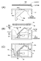
表皮材10の基材4に対する一体成形の真空成形工程を図1を参照して説明する。所要の大きさの表皮材10(図1A)をクランプ具18で扁平状に支持すると共に、基材4をその裏面に沿った型面形状の基材用凸型5aにセットする(図1B)。その際、図2に二点鎖線で示すように、スライドコア20を逃げ位置に後退させて、係止片22で係止した基材アンダカット領域4fを曲げ変形させて空洞状ガイド部29内へ逃がしておく。
The integral forming vacuum forming process for the
次いで、表皮材10をヒータ19で加温処理して軟化状態にする。続いて、このヒータを逃がして真空吸引型5、16をメータフード9aの開口部に沿った方向を型締め方向として昇降させて型締めすると共に、スライドコア20を前進位置に駆動することにより、先端面20aが基材アンダカット領域4fに接面して係止片22で拘束した状態で、基材アンダカット領域4fを基材としての原位置に正確に位置付けする。さらに、吸引口16d基材アンダカット領域4fを含めた基材4の吸気路に連通する凸型5aの吸気路から略同時に真空吸引を行う(図1C)。
Next, the
これにより、基材4には基材アンダカット領域4fを含めて発泡層12がホットメルト型のオレフィン系接着剤13で密着状態に接着されると共に、表皮11は、全域にわたり多孔性の表皮材用凹型16aの型面16bで緊密に吸着され、熱軟化状態の発泡層12を圧縮もしくは膨張させつつ型面16bに沿って賦形され、オールオレフィン3層のインストルメントパネル9が製作される。同時に、型面16bに沿って賦形により、カウル部9bにはアンダカット部4gに相似形状の係合溝7が形成され、係止片22の表面も表面形状を損なわれることなく積層される。
Thereby, the foam layer 12 including the base material undercut
型締め状態での表皮材10が表裏双方からの真空吸引により、デフロスタ収納部8に図5を基に前述したアンダカット部2bを形成する場合でも空洞の発生が回避され、基材4の一般面部のエアバッグドア部分に生じる可能性のある段差或は曲面状のコーナ部でのRだれも解消される。
Even when the undercut
冷却後の真空吸引型16の型開き時には、再度スライドコア20を逃げ位置に後退させて基材アンダカット領域4fを前述の二点鎖線位置に変形させることにより、凸状型部16cで表皮材10を殆ど圧縮させることなく型開きされる。さらに、基材アンダカット領域4fを前進位置へ復帰させた状態で、カウル部9bの基材周面部末端4sを係止片22から離脱させてインストルメントパネル9を凸型5aから取外す。
When opening the vacuum suction die 16 after cooling, the
尚、アンダカット部が浅いために、型締め時に基材アンダカット領域と表皮用キャビティ型の凸状型部とが干渉しない場合、逃げ位置は、凸状型部が型開き時に表皮材を損傷させない程度に設定することができる。カウル部を変形させる範囲は、アンダカット部の車幅方向の幅に応じてスライドコアの幅を拡げることで対応でき、また係止片の個数も相応に増やすこともできる。本発明は、カウル部に限らず、インストルメントパネルの側面又は後面側の周面部、或は凸形プレート状基材に発泡層付き表皮材を一体成形する他の内装品に適用することもできる。 If the base undercut area does not interfere with the convex part of the skin cavity mold during mold clamping because the undercut part is shallow, the relief position will damage the skin material when the convex mold part opens. It can be set to such an extent that it does not occur. The range in which the cowl portion is deformed can be dealt with by increasing the width of the slide core according to the width of the undercut portion in the vehicle width direction, and the number of locking pieces can be increased accordingly. The present invention is not limited to the cowl portion, but can also be applied to a peripheral surface portion on the side surface or rear surface side of the instrument panel, or other interior products in which a skin material with a foam layer is integrally formed on a convex plate-like substrate. .
4 基材
4f 基材アンダカット領域
4g アンダカット部
4m 基材周面部
4s 基材周面部末端
5 基材用凸状真空吸引型
5a 基材用凸型
7 係合溝
9 インストルメントパネル
9b カウル部
10 表皮材
11 表皮
12 発泡層
13 オレフィン系接着剤
16 表皮材用凹状真空吸引型
16a 表皮材用凹型
16c 表皮材用凹型の凸状型部
18 クランプ具
19 ヒータ
20 スライドコア
20a スライドコアの先端面
22 係止片
29 空洞状ガイド部
4
5a Convex mold for
Claims (5)
前記基材用凸状真空吸引型に、その空洞状ガイド部に前進位置及び逃げ位置間でスライド可能にガイドされるスライドコアを設けると共に、このスライドコアの先端面を、前記表皮材用凹状真空吸引型の前記アンダカット部に対応する凸状型部と直接もしくは前記表皮材を介して干渉する前記基材周面部を含めてその前記型締め方向の基材周面部末端に達する範囲の基材アンダカット領域に前進位置で接面するように形成し、さらに前記スライドコアに、前記基材周面部末端を横断し、次いで前記発泡層よりも薄い厚みを伴って前記基材周面部に沿って曲げられたL字形の係止片を設け、
前記真空吸引時には前記スライドコアを前記前進位置に位置付けし、
前記表皮材用凹状真空吸引型の少なくとも型開き時には、前記凸状型部との干渉を回避するように、前記基材アンダカット領域を前記係止片に係止させて前記スライドコアを前記逃げ位置に後退させることにより、前記基材アンダカット領域を前記空洞状ガイド部内へ曲げ変形させることを特徴とする内装品の真空成形方法。 A base plate in which a base plate having a convex plate shape exhibiting flexural elasticity and distributed in the intake passage is set on one of both sides in the vertical direction with respect to a skin material with a thermoplastic foam layer supported in a flat shape A convex vacuum suction mold for a material, and a concave vacuum suction mold for a skin material having a mold surface corresponding to the surface shape of the entire skin to be shaped with respect to the flat shape on the other side, In a state where the material is softened by heating treatment, the foamed layer is formed on the substrate by clamping the convex vacuum suction mold for the base material and the concave vacuum suction mold for the skin material and vacuuming from both sides. In the vacuum forming method of an interior product in which the skin material is shaped along the mold surface of the concave vacuum suction mold for the skin material, and the substrate peripheral surface portion is opened and closed in the concave vacuum suction mold for the skin material With an undercut for the undercut Tsu wherein the surface shape corresponding to the isolation portion cover material is a vacuum forming process for fabricating a decorated article to be shaped,
The convex vacuum suction mold for the base material is provided with a slide core that is slidably guided between the advance position and the escape position in the hollow guide portion, and the front end surface of the slide core is provided with the concave vacuum for the skin material. A base material in a range that reaches the end of the base material peripheral surface in the mold clamping direction, including the base material peripheral surface part that interferes directly or via the skin material with the convex mold part corresponding to the undercut part of the suction mold It is formed so as to contact the undercut region at an advanced position, and further, the slide core crosses the end of the peripheral surface portion of the base material, and then follows the peripheral surface portion of the base material with a thinner thickness than the foamed layer. A bent L-shaped locking piece is provided,
During the vacuum suction, the slide core is positioned at the forward movement position,
At least when the concave vacuum suction mold for the skin material is opened, the base undercut region is locked to the locking piece so as to avoid interference with the convex mold portion, and the slide core is moved away. A vacuum forming method for an interior product, wherein the substrate undercut region is bent and deformed into the hollow guide portion by retreating to a position.
前記基材用凸状真空吸引型に、その空洞状ガイド部に前進位置及び逃げ位置間でスライド可能にガイドされるスライドコアを設けると共に、このスライドコアの先端面が、前記表皮材用凹状真空吸引型の前記アンダカット部に対応する凸状型部と直接もしくは前記表皮材を介して干渉する前記基材周面部を含めてその前記型締め方向の基材周面部末端に達する範囲の基材アンダカット領域に前記前進位置で接面するように形成され、
前記スライドコアに、前記基材アンダカット領域を型開き時に離脱可能に係止する係止片を設けると共に、前記スライドコアを前記前進位置及び後退する前記逃げ位置間で進退駆動するアクチュエータを付属させ、
前記係止片は、前記基材周面部末端を横断し、次いで前記発泡層よりも薄い厚みを伴って前記基材周面部に沿って曲げられたL字形に形成され、
前記逃げ位置が、前記基材アンダカット領域を前記係止片の係止により前記空洞状ガイド部内へ曲げ変形させて前記凸状型部との干渉を回避させるように設定されていることを特徴とする内装品の真空成形機。 A base on which a base plate having a convex plate shape exhibiting flexural elasticity and dispersed in an intake passage is set on one of both sides in the vertical direction with respect to a skin material with a thermoplastic foam layer supported in a flat shape A convex vacuum suction mold for a material, and a concave vacuum suction mold for a skin material having a mold surface corresponding to the surface shape of the entire skin to be shaped with respect to the flat shape on the other side, In a state where the material is softened by heating treatment, the foamed layer is formed on the substrate by clamping the convex vacuum suction mold for the base material and the concave vacuum suction mold for the skin material and vacuuming from both sides. In an interior vacuum forming machine for shaping the skin material along the mold surface of the concave vacuum suction mold for the skin material, the base material peripheral surface portion is open / close direction of the concave vacuum suction mold for the skin material This undercut is provided with an undercut for Wherein a surface shape corresponding to the isolation portion cover material is a vacuum forming machine for fabricating a decorated article to be shaped,
The convex vacuum suction mold for the base material is provided with a slide core that is slidably guided between the advance position and the escape position in the hollow guide portion, and the front end surface of the slide core is a concave vacuum for the skin material. A base material in a range that reaches the end of the base material peripheral surface in the mold clamping direction, including the base material peripheral surface part that interferes directly or via the skin material with the convex mold part corresponding to the undercut part of the suction mold Formed to contact the undercut region at the advance position,
The slide core is provided with a locking piece for releasably locking the base material undercut region when the mold is opened, and an actuator for driving the slide core between the forward position and the backward position is attached. ,
The locking piece is formed in an L shape that traverses the base material peripheral surface end, and then is bent along the base material peripheral surface portion with a thickness smaller than that of the foam layer.
The escape position is set so that the base undercut region is bent and deformed into the hollow guide portion by locking the locking piece to avoid interference with the convex mold portion. Vacuum forming machine for interior products.
Priority Applications (1)
| Application Number | Priority Date | Filing Date | Title |
|---|---|---|---|
| JP2004115094A JP4330481B2 (en) | 2004-04-09 | 2004-04-09 | Vacuum forming method and vacuum forming machine for interior parts |
Applications Claiming Priority (1)
| Application Number | Priority Date | Filing Date | Title |
|---|---|---|---|
| JP2004115094A JP4330481B2 (en) | 2004-04-09 | 2004-04-09 | Vacuum forming method and vacuum forming machine for interior parts |
Publications (3)
| Publication Number | Publication Date |
|---|---|
| JP2005297301A JP2005297301A (en) | 2005-10-27 |
| JP2005297301A5 JP2005297301A5 (en) | 2006-06-29 |
| JP4330481B2 true JP4330481B2 (en) | 2009-09-16 |
Family
ID=35329445
Family Applications (1)
| Application Number | Title | Priority Date | Filing Date |
|---|---|---|---|
| JP2004115094A Expired - Fee Related JP4330481B2 (en) | 2004-04-09 | 2004-04-09 | Vacuum forming method and vacuum forming machine for interior parts |
Country Status (1)
| Country | Link |
|---|---|
| JP (1) | JP4330481B2 (en) |
Families Citing this family (1)
| Publication number | Priority date | Publication date | Assignee | Title |
|---|---|---|---|---|
| JP7058255B2 (en) * | 2019-12-26 | 2022-04-21 | 日本プラスチックス・テクノロジーズ株式会社 | How to make a skin-covered product |
-
2004
- 2004-04-09 JP JP2004115094A patent/JP4330481B2/en not_active Expired - Fee Related
Also Published As
| Publication number | Publication date |
|---|---|
| JP2005297301A (en) | 2005-10-27 |
Similar Documents
| Publication | Publication Date | Title |
|---|---|---|
| JP3313336B2 (en) | Method for manufacturing vehicle interior trim components having a soft touch foam layer | |
| KR100451029B1 (en) | The method for manufacturing and apparatus for catapulting and molding insert cloth | |
| JP4211935B2 (en) | Vacuum forming method and vacuum forming machine for interior parts | |
| JP2005125736A (en) | Interior part with foamed layer | |
| JP4330481B2 (en) | Vacuum forming method and vacuum forming machine for interior parts | |
| JP3822208B2 (en) | Vacuum forming method and vacuum forming machine for interior parts | |
| JP4117796B2 (en) | Vacuum forming method and vacuum forming machine for interior parts | |
| JP6970557B2 (en) | Vehicle interior material molding equipment and vehicle interior material manufacturing method | |
| JPH09131752A (en) | Laminated molding, manufacture thereof and manufacturing mold | |
| JP4819987B2 (en) | LAMINATED RESIN MOLDED ARTICLE AND METHOD FOR PRODUCING THE SAME | |
| KR101124537B1 (en) | The mold for catapulting and operational method insert cloth | |
| JP2951698B2 (en) | Method for producing composite molded article and press mold thereof | |
| JP4117795B2 (en) | Vacuum forming method and vacuum forming machine for interior parts | |
| JP4302072B2 (en) | Vacuum forming machine and vacuum forming method for interior parts | |
| JPS59136255A (en) | Manufacture of composite shape | |
| JP2005280250A (en) | Clad-blow-molded article, and its manufacturing method | |
| KR20070094218A (en) | The method for manufacturing and apparatus for catapulting and molding insert cloth | |
| JP2007223218A (en) | Molding process for laminated molded article and mold | |
| JP4820050B2 (en) | Laminated resin material | |
| JP2006192797A (en) | Vacuum forming method and vacuum forming mold | |
| JP2004009304A (en) | Laminate blow-molding method | |
| JP4440426B2 (en) | Molded product and manufacturing method thereof | |
| JP2010179485A (en) | Method and apparatus for molding laminated molding | |
| JP7374773B2 (en) | Decorative component manufacturing method | |
| JPH1158396A (en) | Manufacture of laminate |
Legal Events
| Date | Code | Title | Description |
|---|---|---|---|
| A521 | Written amendment |
Free format text: JAPANESE INTERMEDIATE CODE: A523 Effective date: 20060517 |
|
| A621 | Written request for application examination |
Free format text: JAPANESE INTERMEDIATE CODE: A621 Effective date: 20060517 |
|
| A977 | Report on retrieval |
Free format text: JAPANESE INTERMEDIATE CODE: A971007 Effective date: 20080407 |
|
| A131 | Notification of reasons for refusal |
Free format text: JAPANESE INTERMEDIATE CODE: A131 Effective date: 20080416 |
|
| A521 | Written amendment |
Free format text: JAPANESE INTERMEDIATE CODE: A523 Effective date: 20080616 |
|
| TRDD | Decision of grant or rejection written | ||
| A01 | Written decision to grant a patent or to grant a registration (utility model) |
Free format text: JAPANESE INTERMEDIATE CODE: A01 Effective date: 20090616 |
|
| A01 | Written decision to grant a patent or to grant a registration (utility model) |
Free format text: JAPANESE INTERMEDIATE CODE: A01 |
|
| A61 | First payment of annual fees (during grant procedure) |
Free format text: JAPANESE INTERMEDIATE CODE: A61 Effective date: 20090616 |
|
| R150 | Certificate of patent or registration of utility model |
Free format text: JAPANESE INTERMEDIATE CODE: R150 |
|
| FPAY | Renewal fee payment (event date is renewal date of database) |
Free format text: PAYMENT UNTIL: 20120626 Year of fee payment: 3 |
|
| LAPS | Cancellation because of no payment of annual fees |