JP4330451B2 - Gripper - Google Patents
Gripper Download PDFInfo
- Publication number
- JP4330451B2 JP4330451B2 JP2003578126A JP2003578126A JP4330451B2 JP 4330451 B2 JP4330451 B2 JP 4330451B2 JP 2003578126 A JP2003578126 A JP 2003578126A JP 2003578126 A JP2003578126 A JP 2003578126A JP 4330451 B2 JP4330451 B2 JP 4330451B2
- Authority
- JP
- Japan
- Prior art keywords
- gripper
- contact lens
- channel
- opening
- arc
- Prior art date
- Legal status (The legal status is an assumption and is not a legal conclusion. Google has not performed a legal analysis and makes no representation as to the accuracy of the status listed.)
- Expired - Fee Related
Links
- 239000007788 liquid Substances 0.000 description 28
- XLYOFNOQVPJJNP-UHFFFAOYSA-N water Substances O XLYOFNOQVPJJNP-UHFFFAOYSA-N 0.000 description 23
- 239000011796 hollow space material Substances 0.000 description 7
- 238000004519 manufacturing process Methods 0.000 description 6
- 238000003780 insertion Methods 0.000 description 5
- 230000037431 insertion Effects 0.000 description 5
- 238000007689 inspection Methods 0.000 description 4
- 239000011888 foil Substances 0.000 description 3
- 239000011521 glass Substances 0.000 description 3
- 238000004806 packaging method and process Methods 0.000 description 3
- 229930040373 Paraformaldehyde Natural products 0.000 description 2
- 238000013461 design Methods 0.000 description 2
- 238000010586 diagram Methods 0.000 description 2
- 238000000605 extraction Methods 0.000 description 2
- 229920006324 polyoxymethylene Polymers 0.000 description 2
- FAPWRFPIFSIZLT-UHFFFAOYSA-M Sodium chloride Chemical compound [Na+].[Cl-] FAPWRFPIFSIZLT-UHFFFAOYSA-M 0.000 description 1
- 238000013270 controlled release Methods 0.000 description 1
- 230000001419 dependent effect Effects 0.000 description 1
- 238000003384 imaging method Methods 0.000 description 1
- 238000007373 indentation Methods 0.000 description 1
- 230000002452 interceptive effect Effects 0.000 description 1
- 238000000034 method Methods 0.000 description 1
- 230000003287 optical effect Effects 0.000 description 1
- -1 polyoxymethylene Polymers 0.000 description 1
- 238000003825 pressing Methods 0.000 description 1
- 238000012545 processing Methods 0.000 description 1
- 150000003839 salts Chemical class 0.000 description 1
- 238000000926 separation method Methods 0.000 description 1
- 239000011780 sodium chloride Substances 0.000 description 1
- 238000003860 storage Methods 0.000 description 1
- 238000012360 testing method Methods 0.000 description 1
Images


Classifications
-
- B—PERFORMING OPERATIONS; TRANSPORTING
- B29—WORKING OF PLASTICS; WORKING OF SUBSTANCES IN A PLASTIC STATE IN GENERAL
- B29D—PRODUCING PARTICULAR ARTICLES FROM PLASTICS OR FROM SUBSTANCES IN A PLASTIC STATE
- B29D11/00—Producing optical elements, e.g. lenses or prisms
- B29D11/00009—Production of simple or compound lenses
- B29D11/00038—Production of contact lenses
- B29D11/00125—Auxiliary operations, e.g. removing oxygen from the mould, conveying moulds from a storage to the production line in an inert atmosphere
- B29D11/0023—Transferring contact lenses
- B29D11/0024—Transferring contact lenses using a vacuum suction gripper
Landscapes
- Engineering & Computer Science (AREA)
- Health & Medical Sciences (AREA)
- Manufacturing & Machinery (AREA)
- Ophthalmology & Optometry (AREA)
- Mechanical Engineering (AREA)
- Eyeglasses (AREA)
- Lens Barrels (AREA)
- Transition And Organic Metals Composition Catalysts For Addition Polymerization (AREA)
- Advancing Webs (AREA)
- Feeding Of Articles By Means Other Than Belts Or Rollers (AREA)
Abstract
Description
本発明は、独立した請求項の前文によるグリッパに関する。 The invention relates to a gripper according to the preamble of the independent claim.
一般的に、オートメーション化されたコンタクトレンズの生産において、例えば使い捨てレンズのように、特にコンタクトレンズの大規模なバッチの生産において、生産工程のあるステーションで、コンタクトレンズを安全に、素早く、効率的に、扱うことができることが必要である。そのようにコンタクトレンズを扱う一例は、前記コンタクトレンズを、コンタクトレンズを(例えば画像処理で)検査するため液体中に、例えば水中に置いた検査室からコンタクトレンズを取り出すときである。 In general, in the production of automated contact lenses, for example disposable lenses, especially in the production of large batches of contact lenses, contact lenses can be safely, quickly and efficiently used at the production process station. It is necessary to be able to handle it. One example of handling such a contact lens is when the contact lens is removed from an examination room placed in a liquid, for example in water, for inspecting the contact lens (eg by image processing).
検査したコンタクトレンズをそのような検査室から取り出すために、グリッパと呼ばれる装置が使用され、そのような生産工程において他のステーションでも用いられる。コンタクトレンズはそのようなグリッパの助けを借りて把持され、上述の例において、検査室から取り出される。そのあと、例えばコンタクトレンズは、コンタクトレンズの最終包装の部分となり得て、かつ、貯蔵溶液(例えば、含塩水)が供給される容器の中に置かれる。そのあと、容器は溶接され、又はカバーフォイルで封印され、そして、オートクレーブで消毒されたのち、最終包装は販売のため解放され得る。 In order to remove the inspected contact lens from such an examination room, a device called a gripper is used, which is also used at other stations in such a production process. The contact lens is gripped with the help of such a gripper and in the above example removed from the laboratory. Thereafter, for example, the contact lens can be part of the final packaging of the contact lens and placed in a container to which a storage solution (eg, saline) is supplied. After that, after the container is welded or sealed with a cover foil and sterilized by autoclaving, the final package can be released for sale.
上述した検査室からコンタクトレンズを取り出し、次いで含塩水が存在する容器にコンタクトレンズを入れる場合に、コンタクトレンズとともに、極めて少量の水しか、好ましくはまったく水が、同伴されないことを確実にするために注意しなければならない。理由は、上述の検査室中のコンタクトレンズを(結果として、水が必然的にレンズとともに吸引される)“水面下”から吸引し、次いで最終包装の部分である容器に運び、最終的にはこの容器の中に入れなければならないからである。コンタクトレンズをグリッパから再度解放しなければならない目的のために、これは解決することが非常に難しい問題である。加えて、コンタクトレンズをグリッパにより(たとえ“水面下”でさえ)確実に把持しなければならず、かつ小さな容器では、その後容器の溶接や封印されている間、カバーフォイルにより損傷を受けないように、コンタクトレンズを確実に容器の中央に入れなければならない。 To ensure that no very small amount of water, preferably no water, is entrained with the contact lens when the contact lens is removed from the laboratory described above and then placed in a container containing salt water. You must be careful. The reason is that the contact lens in the laboratory mentioned above is sucked from “under the water” (as a result, water is inevitably sucked together with the lens) and then transported to the container that is part of the final package, and finally This is because it must be put in this container. This is a very difficult problem to solve for the purpose of having to re-release the contact lens from the gripper. In addition, the contact lens must be securely gripped by the gripper (even “under the water”) and small containers will not be damaged by the cover foil while the container is subsequently welded or sealed. In addition, the contact lens must be securely placed in the center of the container.
本発明の目的は、前述の要求を満たすことができるグリッパを、言い換えれば、一方では、“水面下”でも適切であり、そして同伴される液体(例えば水)の量が非常に少ない(例えばおおよそ40マイクロリッターよりも少ない)ことを確実にする場合において、コンタクトレンズを確実に把持するグリッパを提供することである。他方では、コンタクトレンズを容器の中央に確実に入れることができなければならず、そのために高度に制御されたグリッパからのコンタクトレンズの解放を達成しなければならない。 The object of the present invention is a gripper that can meet the aforementioned requirements, in other words it is also suitable “under the surface” and the amount of entrained liquid (eg water) is very small (eg approximately It is to provide a gripper that reliably grips the contact lens in the case of less than 40 microliters). On the other hand, it must be possible to ensure that the contact lens can be placed in the middle of the container, for which purpose a highly controlled release of the contact lens from the gripper must be achieved.
この目的は、独立請求項の特徴により特徴付けられる発明によるグリッパによって達成される。特に、本発明によるグリッパの有利な実施態様は、従属請求項の特徴から明らかになるだろう。 This object is achieved by a gripper according to the invention which is characterized by the features of the independent claims. In particular, advantageous embodiments of the gripper according to the invention will become apparent from the features of the dependent claims.
特に、本発明のグリッパは、コンタクトレンズの支持面を有するグリッパヘッドを含み、グリッパヘッドには1以上の開口が設けられ、開口を通して、支持面に対してコンタクトレンズを吸引するため負圧を供給し、かつ、支持面からコンタクトレンズを解放するための加圧を供給する。グリッパヘッドには複数の開口を互いに連結するチャンネルが備えられている。グリッパヘッドに備えられたチャンネルの助けを借りて複数の開口を(できる限り全ての開口さえも)連結することにより、一方では、負圧の供給で、コンタクトレンズを複数の場所で同時に支持面に対して吸引するため、グリッパヘッドの支持面に対してコンタクトレンズを確実に吸引することができ、そして、他方では、同様の理由から、加圧の供給で、コンタクトレンズを安全にかつ慎重な方法で容器、例えば最終包装の部分を形成する容器の中央に入れられ得ることを、既にはじめに説明したように確実にすることができる。 In particular, the gripper of the present invention includes a gripper head having a contact lens support surface, and the gripper head is provided with one or more openings, through which the negative pressure is supplied to attract the contact lens to the support surface. And applying pressure to release the contact lens from the support surface. The gripper head is provided with a channel for connecting a plurality of openings to each other. By connecting multiple apertures (even all apertures as much as possible) with the help of the channels provided in the gripper head, on the one hand, with the supply of negative pressure, the contact lens can be simultaneously applied to the support surface in multiple locations. Because of the suction, the contact lens can be reliably sucked against the support surface of the gripper head, and on the other hand, for the same reason, the contact lens can be safely and prudently supplied with pressure. It can be ensured, as already explained, that it can be placed in the middle of a container, for example the container forming part of the final packaging.
例えばこの場合、チャンネルは(比較的狭くかつかなり浅い)溝として設計されても良い。従って、存在する複数の開口又は存在する全ての開口を通して負圧又は加圧を同時に供給することができ、それにより、同時に全ての開口を通して、支持面に対してコンタクトレンズを吸引し、あるいは、支持面からコンタクトレンズを解放することができる。 For example, in this case, the channel may be designed as a groove (relatively narrow and fairly shallow). Thus, negative pressure or pressurization can be supplied simultaneously through a plurality of existing openings or all existing openings, so that the contact lens is sucked or supported against the support surface through all the openings simultaneously. The contact lens can be released from the surface.
上述したように、例えばコンタクトレンズを液体(例えば水)がある検査室の中に置くと、コンタクトレンズを把持操作で“水面下”から吸引し、そして液体がコンタクトレンズの背面とグリッパヘッドの支持面との間にあることがたまたま起こり得る。そのような溜り液体を、グリッパヘッドの支持面を対して置かれているコンタクトレンズとともに、チャンネルを通して吸引することができ、結果として同伴する水の量を非常に少なく保つことができる。 As described above, for example, when a contact lens is placed in an examination room with a liquid (eg, water), the contact lens is sucked from “under the water” by a gripping operation, and the liquid supports the back of the contact lens and the gripper head. It can happen to be between the faces. Such pooled liquid can be sucked through the channel together with the contact lens placed against the gripper head support surface, resulting in a very small amount of entrained water.
グリッパの設計は、複数の開口が円弧上に配置され、一つの開口が円弧の中心にも配置されることが、有利である。このグリッパの設計では、コンタクトレンズをグリッパヘッドの支持面に対して特に確実に吸引することができ、そして同様に確実にかつ慎重なコンタクトレンズの解放を可能にもさせる。この目的のため、別個のチャンネルは円弧の中心の開口から始まり、円弧上に配置された各々の開口に延びるように(いわばスター形で)設けられ、チャンネルは中心の開口を円弧上にある各々の開口に連結することができる。 The gripper design advantageously has a plurality of openings arranged on an arc and one opening is also arranged at the center of the arc. This gripper design allows the contact lens to be attracted particularly reliably against the support surface of the gripper head and also allows a reliable and careful release of the contact lens. For this purpose, a separate channel is provided (starting in a so-called star shape) starting from the central opening of the arc and extending to each opening arranged on the arc, and each channel has a central opening on the arc. Can be connected to the opening.
その上、円弧の中心の開口と円弧上にある各々の開口とを連結する各々のチャンネルが、円弧上にある開口を越えて放射状に外側に延びる場合が、有利であり得る。このことは、負圧の供給で、空気が常に確実に吸引されることが可能であり、結果として、液体が常に運び去られ得ることを保証し、これにより同伴される水の量を非常に少なく保つことができる。 Moreover, it may be advantageous if each channel connecting the opening in the center of the arc and each opening on the arc extends radially outward beyond the opening on the arc. This ensures that with a negative pressure supply, air can always be reliably aspirated and as a result the liquid can always be carried away, thereby greatly reducing the amount of water entrained. Can be kept low.
開口を相互に連結するチャンネルが(吸引された後コンタクトレンズが乗っている)支持面に備えられている場合、コンタクトレンズと支持面との間に捕捉された液体を特に容易に吸引することができるため、特に有利である。 If the support surface (on which the contact lens rests after being aspirated) is provided on the support surface that interconnects the openings, it is particularly easy to aspirate the liquid trapped between the contact lens and the support surface This is particularly advantageous because it can.
可能な限り少ない液体の同伴を保証するために、更に有利な実施態様においては、グリッパの外面は平滑で、かつ特に液体が集まることができるくぼみを有さない。 In order to ensure as little liquid entrainment as possible, in a further advantageous embodiment, the outer surface of the gripper is smooth and in particular has no indentation in which liquid can collect.
さらに有利な実施態様において、本発明によるグリッパはグリッパヘッドの中の開口に導く負圧チャンネルを有し、かつ同様にグリッパヘッドの中の開口に導く加圧チャンネルを有し、加圧チャンネルと負圧チャンネルとは本質的に相互に離間している。本質的に負圧チャンネルと加圧チャンネルとを別個に設けることは、加圧のみ又は負圧のみをかけることができ、又は両方ともかけることができる。コンタクトレンズを置いたとき、例えば実際上未だグリッパヘッドの内側に水が存在することがあり、コンタクトレンズを置く前に水を吸い出すべきである。コンタクトレンズを入れる容器にこの水が同伴しないことを保証するために、グリッパヘッドの内側に位置し、かつ未だ吸い出されていない水を負圧チャンネルに追いやることを加圧が保証する場合、加圧及び負圧のいずれもが短期間で供給されることが可能であり、その結果、この水が吸い出された後、コンタクトレンズを慎重な方法でかつ順調に支持面から解放することができ、この水の同伴を回避する。 In a further advantageous embodiment, the gripper according to the invention has a negative pressure channel leading to the opening in the gripper head and also has a pressure channel leading to the opening in the gripper head, The pressure channels are essentially spaced from one another. Essentially providing a negative pressure channel and a pressure channel separately can apply only pressure, only negative pressure, or both. When a contact lens is placed, for example, water may still be present inside the gripper head in practice and should be siphoned before placing the contact lens. To ensure that this water is not entrained in the container containing the contact lens, if pressurization ensures that water that is located inside the gripper head and has not yet been aspirated is repelled into the negative pressure channel, Both pressure and negative pressure can be supplied in a short period of time, so that after this water has been sucked out, the contact lens can be released from the support surface in a careful manner and smoothly. Avoid this water entrainment.
このために、負圧チャンネルが加圧チャンネルを形成するグリッパの内側を通して延び、かつグリッパヘッドの中の開口から短い距離で終了するチューブにより形成される本発明によるグリッパの実施態様は有利であり得る。この場合、負圧チャンネルを形成するチューブは、グリッパヘッドの開口から、0.1mmから5mmの距離で、好ましくは約1mmの距離で終了することができる。 For this purpose, an embodiment of the gripper according to the invention in which the negative pressure channel extends through the inside of the gripper forming the pressure channel and is formed by a tube that ends at a short distance from the opening in the gripper head can be advantageous. . In this case, the tube forming the negative pressure channel can be terminated at a distance of 0.1 mm to 5 mm, preferably about 1 mm, from the opening of the gripper head.
さらに、本発明は、前述の実施態様の一つで説明したグリッパと、内側の壁に気体状の媒体、例えば空気を供給することが可能であるノズルを有するノズルリングとを備えるコンタクトレンズの把持装置に関する。グリッパとノズルリングとは、グリッパが把持されるコンタクトレンズに向かってノズルリングを通って移動することができ、かつ、コンタクトレンズが把持された後、再びノズルリングを通ってコンタクトレンズとともに戻ることができるように設計されている。グリッパがノズルリングを通って戻ると、コンタクトレンズの外に付着する液体、例えば水を吹き飛ばすことができるように(例えば、ノズルリングが前述した検査室の上に配置されている場合、吹き飛ばされた液体は再度検査室により集められることができる)、コンタクトレンズは気体状の媒体の作用を受けることができ、そしてこのように液体の同伴をさらに減少させることができる。Furthermore, the present invention provides a gripping contact lens comprising the gripper described in one of the previous embodiments and a nozzle ring having a nozzle capable of supplying a gaseous medium, for example air, to the inner wall. Relates to the device. The gripper and nozzle ring can move through the nozzle ring toward the contact lens on which the gripper is gripped, and after the contact lens is gripped, it can return with the contact lens again through the nozzle ring. Designed to be able to. When the gripper returns through the nozzle ring, it can be blown away so that any liquid that adheres to the outside of the contact lens, such as water, can be blown away (for example, if the nozzle ring is placed on the aforementioned test chamber) The liquid can be collected again by the examination room), the contact lens can be subjected to the action of a gaseous medium, and in this way the liquid entrainment can be further reduced.
さらに有利な構成は、説明図及び/又は断面図を示した図面を参照して、本発明の以下の図示した実施態様の説明から明らかになるだろう。 Further advantageous configurations will become apparent from the following description of the illustrated embodiment of the invention, with reference to the drawing figures and / or to the drawing showing a sectional view.
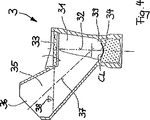
以下に図1から図3を参照して説明する本発明によるグリッパ1の図示された実施態様は、支持面100を備えるグリッパヘッド10を有する。複数の開口101は、図2から分るように、グリッパヘッド10の中に設けられている。ここで示された図示された実施態様では、開口101は円弧上に配置され、一つの開口102が円弧の中心に配置されている。別個のチャンネル103は円弧の中心の開口102から始まり、(いわばスター形で)円弧上にある各開口101に延び、チャンネル103は円の中心の開口102を円弧上にある各々の開口101に連結する。チャンネル103は支持面100の中に溝として設計されており、片面で開口し、かつ円弧上にある各々の開口101を越えて放射状に外方向に延びている。図示しない実施態様であるが、開口101は、例えば円弧の形状でチャンネルを介して相互に接続されることもできる。
The illustrated embodiment of the
グリッパヘッド10を接合するため、グリッパ1はグリッパヘッド10と一体的に形成される円筒形のパーツ11を有し、かつ全体として、例えばPOM(ポリオキシメチレン)のようなプラスチックから作られたパーツ12を形成する。全体として、グリッパ1は、特にパーツ12は、液体が集まりかつ同伴され得るくぼみのない平滑面を有する。
In order to join the
パーツ12の内側120を通して延びるため、負圧チャンネルとして機能することができ、かつ開口101及び中心の開口102から短い距離dで終わるチューブ13がある。この距離dは約0.1mmから約5mmの範囲内であることができ、好ましくは1mmである。内側120それ自身は加圧チャンネルを形成することができ、本発明によるグリッパ1の示された実施態様が機能する方法の記載において、以下により詳細に説明される。加圧チャンネルと負圧チャンネルとはこのように相互に離間しており、近接する開口101、102の近傍でチューブ13の端部だけは離れずに存在し得る。
Because it extends through the
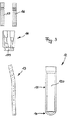
グリッパ1の円筒形のパーツ12を接合するため、パーツ12を接続でき、かつチューブ13と加圧及び負圧の供給(図示せず)に対応するアタッチメント部品15、16に対する受け穴143を有するアダプタ部品14がある。アタッチメント部品15、16、アダプタ部品14、そして円筒形のパーツ11とグリッパヘッド10を有するパーツ12は、図3において個別の部品として示されているのに対して、図1のグリッパ1は組み立てられた状態で示されている。図3からわかるように、個別の部品全ては旋盤にかけられ簡単に製造される部品であり、その結果、個別の部品を製造するために要求される費用が相対的に小さく、そのことは本発明によるグリッパ1のさらに顕著な利点を構成することになるだろう。
Adapter for connecting
ここで、グリッパ1が機能する方法を説明するために、冒頭で触れた例について言及し、すなわちコンタクトレンズCLを検査室3から取り出すこと、及び、このことが図4と図5とを参照して以下に詳細に説明される。ここで検査室3は、図4に示されている検査位置では検査装置(ここでは図示しない)の光学軸と一致する、第1の軸32に沿って延びる中空の空間31を有するように設計されている。中空の空間31は覗きガラス33により上から区切られている。中空の空間31の下部の領域は、図4によるとコンタクトレンズCLは検査位置において受け取られる検査トラフ34として設計されている。検査室3は液体、例えば水で満たされ、検査位置の液体のレベル38は、結像を干渉する液体の境界面がなく、かつ液体と覗きガラス33の間に気泡が存在しないように、覗きガラスより上にある。
Here, in order to explain how the
中空の空間31に通じるため、コンタクトレンズCLを中空の空間31に、例えば本発明によるグリッパ1によって、挿入することが可能である外部開口36を有する挿入チャンネル35がある。挿入チャンネル35は、中空の空間31の第1の軸32と約45°の角度である第2の軸37に沿って実質的に一直線に延びている。ここで、一直線であることは、直線状に動くグリッパ1がコンタクトレンズCLを置くため又は取り出すために中空の空間31に挿入チャンネル35を通すことができることを示すことを意図している。
In order to communicate with the hollow space 31, there is an
図4と図5との比較から分かるように、示された検査室3は検査位置(図4)と取り出し位置(図5)との間で回転可能である。図5に示された検査室3の取り出し位置において、挿入チャンネル35の軸37は垂直になり、その結果コンタクトレンズCLは本発明によるグリッパ1の助けを借りて上から取り出すことが可能である。
As can be seen from the comparison between FIG. 4 and FIG. 5, the
この目的のため、グリッパ1はノズルリング2を通して、検査室3が取り出し位置(図5)にあるとき、取り出しトラフ39中に置かれるコンタクトレンズCLに向けて移動し、その動作は以下にさらに説明される。ひとたびグリッパ1がコンタクトレンズCLに到達すると、負圧が供給され、コンタクトレンズCLがグリッパヘッド10の支持面100に対して吸引される。コンタクトレンズCLを吸引するため、負圧は全ての開口101及び102を通してチューブ37を経由して供給され、コンタクトレンズが均一なかつ確実な方法で吸引されるという結果になる。この吸引している間、当然液体、この場合は水も吸い上げられることも起こり得る。
For this purpose, the
負圧が供給されたまま、支持面100上に吸引されたコンタクトレンズCLと一緒にグリッパ1は挿入チャンネル35から再度上方に移動させられる。そうすることにより、支持面100上に吸引されたコンタクトレンズCLと一緒にグリッパ1は、内壁から内側に面し、かつノズルリング2に備えられた供給チャンネル21を通して気体状の媒体を供給するノズル20を有するノズルリング2を通して移動させられる。ノズルリング2は、送り込む空気(又は他の気体状の媒体)が供給チャンネル21に送り込まれ、かつノズル20を通して送り込まれる送風空気送出手段22を備える。
The
支持面100上に吸引されたコンタクトレンズCLと一緒にグリッパ1がノズルリング2を通り抜けると、コンタクトレンズCLの外側に付着した液体はノズル20から出る送風空気の助けでコンタクトレンズCLから吹き飛ばされる。ノズルリング2を検査室3の直上に配置する図示において、吹き飛ばされた液体は検査室3により集めることが可能である。特にこのノズルリング2の配置は有利であるが、少ない液体(この場合は水)の同伴の場合、コンタクトレンズCLから吹き飛ばされた液体は検査室3により集められることは必須ではないため、強制的ではない。
When the
水がコンタクトレンズCLとグリッパヘッド10の支持面100との間に閉じ込められる(コンタクトレンズが表面上に吸引されるとき非常に容易に起こり得る)と、表面上に吸引されたコンタクトレンズCLとともにこの水は、支持面100上のチャンネル103(溝)を経由して開口101と102を通過し、かつそこから内側120へ通ることが可能である。負圧が供給されている限りは、液体は徐々にチューブ13を通り吸い出される。したがって、開口からチューブ37の端まで距離dは、内側120へと開口101と102を通る液体が効果的にそこから吸い出されるように選択される。
When water is confined between the contact lens CL and the support surface 100 of the gripper head 10 (which can happen very easily when the contact lens is sucked onto the surface), this is brought together with the contact lens CL sucked onto the surface. Water can pass through the
コンタクトレンズCLを検査室3から取り出した後、グリッパヘッド10の支持面100上に吸引されたコンタクトレンズCLとともにグリッパ1をコンタクトレンズCLが入れられる為にある最終包装の容器(図示しない)の上に移動させても良い。容器へのグリッパ1の移動の間、液体は全時間吸い出され、その結果、極めて僅かな液体を、好ましくはまったく液体を有さないが、コンタクトレンズCL又は容器の中のグリッパ1とともに運ぶ。コンタクトレンズCLを入れることができ、かつ最終包装の部品を形成する容器は、EPA−0680895の例に記載され、容器がカバーフォイルの助けを借りて密閉されるときコンタクトレンズは損害を受けることはないようにコンタクトレンズを、コンタクトレンズが比較的正確な位置に置かれる受け入れトラフを有する。
After the contact lens CL is taken out from the
容器の受け入れトラフにコンタクトレンズを置く為に、グリッパ1を容器の受け入れトラフを横断して移動させる。加圧チャンネルを経由して、すなわち内側120を経由して加圧が供給される。そうすることにおいて、同時にチューブ13の中では負圧を維持することが可能であり、同時に加圧と負圧を供給する結果として、開口近傍の内側120にまだ存在するだろう液体を、加圧によってチューブ13の方向に押し出し、支配的な負圧によりそこから吸い出す。所定の一定期間が経過した後、負圧の供給は止められ、その結果、加圧(例えば送風空気)だけが供給される。開口101と102を通して供給される加圧は、グリッパヘッド10の支持面100の上にあるコンタクトレンズCLが制御され一定の方法でグリッパヘッド10の支持面100から解放される(吹き飛ばされる)ことを確実にし、その結果、コンタクトレンズは例えば最終包装の容器の受け入れトラフに制御され正確な方法で置かれる。
To place the contact lens on the receiving trough of the container, the
検査室からコンタクトレンズを取り出し、次いで最終包装の容器の中にコンタクトレンズを置くため、本発明によるグリッパの上述の使用は、グリッパの可能性のある一つの使用の例としてのみ見られるものである。もちろんグリッパは、コンタクトレンズ、例えばメス型側からコンタクトレンズを取り出すコンタクトレンズのオートメーション化された生産工程の他のステーションでも、又は、コンタクトレンズを他の理由のため移し変えられなければならないステーションでも使用することができる。 The above use of the gripper according to the present invention is only seen as an example of one possible use of the gripper for removing the contact lens from the laboratory and then placing the contact lens in the container of the final package. . Of course, the gripper is also used in other stations in the automated production process of contact lenses, for example taking out contact lenses from the female side, or in stations where contact lenses must be transferred for other reasons. can do.
Claims (10)
Applications Claiming Priority (2)
| Application Number | Priority Date | Filing Date | Title |
|---|---|---|---|
| EP02006341 | 2002-03-21 | ||
| PCT/EP2003/002919 WO2003080320A1 (en) | 2002-03-21 | 2003-03-20 | Gripper |
Publications (3)
| Publication Number | Publication Date |
|---|---|
| JP2005520714A JP2005520714A (en) | 2005-07-14 |
| JP2005520714A5 JP2005520714A5 (en) | 2006-05-11 |
| JP4330451B2 true JP4330451B2 (en) | 2009-09-16 |
Family
ID=27838024
Family Applications (1)
| Application Number | Title | Priority Date | Filing Date |
|---|---|---|---|
| JP2003578126A Expired - Fee Related JP4330451B2 (en) | 2002-03-21 | 2003-03-20 | Gripper |
Country Status (7)
| Country | Link |
|---|---|
| US (1) | US6994386B2 (en) |
| EP (1) | EP1490209B1 (en) |
| JP (1) | JP4330451B2 (en) |
| AT (1) | ATE316459T1 (en) |
| AU (1) | AU2003219087A1 (en) |
| DE (1) | DE60303367T2 (en) |
| WO (1) | WO2003080320A1 (en) |
Cited By (2)
| Publication number | Priority date | Publication date | Assignee | Title |
|---|---|---|---|---|
| KR20150025246A (en) * | 2013-08-28 | 2015-03-10 | 삼성전기주식회사 | Lens demolding device and the lens demolding method |
| KR20150035254A (en) | 2013-09-27 | 2015-04-06 | 삼성전기주식회사 | Lens demolding system and the lens demolding method |
Families Citing this family (15)
| Publication number | Priority date | Publication date | Assignee | Title |
|---|---|---|---|---|
| MY140797A (en) * | 2005-05-13 | 2010-01-15 | Novartis Ag | Gripper for moving and positioning contact lenses |
| ES2318932B1 (en) | 2006-01-23 | 2010-02-09 | Fundacion Fatronik | MACHINE FOR SHEET CONFORMING AND CONFORMING PROCEDURE. |
| WO2008012152A1 (en) * | 2006-06-26 | 2008-01-31 | Novartis Ag | Method and device for singulating ophthalmic lenses |
| WO2008000417A1 (en) * | 2006-06-26 | 2008-01-03 | Novartis Ag | Method and apparatus for cleaning of ophthalmic lenses |
| EP1927409A1 (en) * | 2006-11-30 | 2008-06-04 | Bausch & Lomb Incorporated | Method for handling contact lens |
| NZ597819A (en) | 2007-04-26 | 2012-09-28 | Adept Technology Inc | Optical sensor for a robotic arm with a light source, segmented mirror ring and a camera |
| CN102481735B (en) * | 2009-09-04 | 2015-12-16 | 诺华股份有限公司 | For the grabber of contact lenses with for carrying the method for contact lenses |
| US9296160B2 (en) * | 2009-09-11 | 2016-03-29 | Coopervision International Holding Company, Lp | Method for moving wet ophthalmic lenses during their manufacture |
| SG10201406686XA (en) * | 2009-10-16 | 2014-12-30 | Novartis Ag | Method and device for removing a contact lens from a container |
| EP2640568B1 (en) | 2010-11-19 | 2016-08-17 | Novartis AG | Gripper for grasping an ophthalmic lens immersed in a liquid |
| EP2602099B1 (en) * | 2011-12-08 | 2014-02-12 | Harro Höfliger Verpackungsmaschinen GmbH | Vacuum gripper and handling system for contact lenses |
| USD829778S1 (en) * | 2016-06-27 | 2018-10-02 | Ngk Spark Plug Co. Ltd. | Vacuum chuck |
| SG11202102473YA (en) | 2018-10-25 | 2021-05-28 | Alcon Inc | Gripper for an ophthalmic contact lens and process for transporting an ophthalmic contact lens |
| US11852902B2 (en) | 2020-01-16 | 2023-12-26 | Alcon Inc. | Cleaner for cleaning grippers for ophthalmic lenses |
| US20220152958A1 (en) * | 2020-11-17 | 2022-05-19 | Alcon Inc. | Mold unit for molding ophthalmic lenses |
Family Cites Families (10)
| Publication number | Priority date | Publication date | Assignee | Title |
|---|---|---|---|---|
| US3134208A (en) * | 1962-01-08 | 1964-05-26 | Clyde S Mccain | Lens holding device |
| US3879076A (en) * | 1973-12-27 | 1975-04-22 | Robert O Barnett | Method and apparatus for applying and removing a soft contact lens |
| CN1086165C (en) * | 1997-06-19 | 2002-06-12 | 博士伦公司 | Transfer and centering system for contact lenses |
| US6032997A (en) * | 1998-04-16 | 2000-03-07 | Excimer Laser Systems | Vacuum chuck |
| US6254155B1 (en) * | 1999-01-11 | 2001-07-03 | Strasbaugh, Inc. | Apparatus and method for reliably releasing wet, thin wafers |
| US6494021B1 (en) * | 1999-02-18 | 2002-12-17 | Johnson & Johnson Vision Care, Inc. | Contact lens transfer and material removal system |
| US6279976B1 (en) * | 1999-05-13 | 2001-08-28 | Micron Technology, Inc. | Wafer handling device having conforming perimeter seal |
| EP1136241B1 (en) * | 2000-03-16 | 2006-06-21 | Novartis AG | Apparatus for the removal of contact lenses |
| JP4634629B2 (en) * | 2000-03-16 | 2011-02-16 | ノバルティス アーゲー | Contact lens removal device |
| US6398277B1 (en) * | 2001-03-15 | 2002-06-04 | Mcdonald Marguerite B. | Contact lens insertion device |
-
2003
- 2003-03-12 US US10/386,951 patent/US6994386B2/en not_active Expired - Lifetime
- 2003-03-20 AT AT03714861T patent/ATE316459T1/en not_active IP Right Cessation
- 2003-03-20 DE DE60303367T patent/DE60303367T2/en not_active Expired - Lifetime
- 2003-03-20 EP EP03714861A patent/EP1490209B1/en not_active Expired - Lifetime
- 2003-03-20 JP JP2003578126A patent/JP4330451B2/en not_active Expired - Fee Related
- 2003-03-20 WO PCT/EP2003/002919 patent/WO2003080320A1/en active IP Right Grant
- 2003-03-20 AU AU2003219087A patent/AU2003219087A1/en not_active Abandoned
Cited By (3)
| Publication number | Priority date | Publication date | Assignee | Title |
|---|---|---|---|---|
| KR20150025246A (en) * | 2013-08-28 | 2015-03-10 | 삼성전기주식회사 | Lens demolding device and the lens demolding method |
| KR102127820B1 (en) * | 2013-08-28 | 2020-06-29 | 삼성전기주식회사 | Lens demolding device and the lens demolding method |
| KR20150035254A (en) | 2013-09-27 | 2015-04-06 | 삼성전기주식회사 | Lens demolding system and the lens demolding method |
Also Published As
| Publication number | Publication date |
|---|---|
| JP2005520714A (en) | 2005-07-14 |
| WO2003080320A1 (en) | 2003-10-02 |
| US20030178862A1 (en) | 2003-09-25 |
| ATE316459T1 (en) | 2006-02-15 |
| EP1490209B1 (en) | 2006-01-25 |
| DE60303367T2 (en) | 2006-10-26 |
| AU2003219087A1 (en) | 2003-10-08 |
| DE60303367D1 (en) | 2006-04-13 |
| US6994386B2 (en) | 2006-02-07 |
| EP1490209A1 (en) | 2004-12-29 |
Similar Documents
| Publication | Publication Date | Title |
|---|---|---|
| JP4330451B2 (en) | Gripper | |
| US9272424B2 (en) | Gripper for a contact lens and process for transporting a contact lens | |
| US8801067B2 (en) | Gripper for grasping an ophthalmic lens immersed in a liquid | |
| US7973915B2 (en) | Method and apparatus for inverting a flexible molding | |
| US20040074525A1 (en) | Transfer apparatus and method and a transfer apparatus cleaner and method | |
| US10053249B2 (en) | Method for transporting a packaging shell of an ophthalmic lens package | |
| JP5783244B2 (en) | Lens barrel manufacturing method | |
| JP5760520B2 (en) | Leak inspection device | |
| ES2718310T3 (en) | Procedure and device for feeding injection molding parts | |
| US20230271337A1 (en) | Gripper for the transportation of an ophthalmic lens | |
| US8651774B2 (en) | Method and device for removing a contact lens from a container | |
| JP2006102655A (en) | Apparatus and method for forcibly feeding material | |
| KR101808059B1 (en) | Contact lens manufacturing apparatus | |
| CN114073798B (en) | Manufacturing container | |
| WO2024184826A1 (en) | Gripper system for an ophthalmic lens | |
| TW202436084A (en) | Gripper system for an ophthalmic lens | |
| JP2007163264A (en) | Gasket position correcting device of syringe | |
| TW200528379A (en) | A transfer apparatus and method and a transfer apparatus cleaner and method | |
| EP1650128A1 (en) | A transfer apparatus and method and a transfer apparatus cleaner and method | |
| JP2012183456A (en) | Article conveying apparatus | |
| JPH0450532B2 (en) | ||
| JP2016199276A (en) | Liquid discharger and container with the same |
Legal Events
| Date | Code | Title | Description |
|---|---|---|---|
| A521 | Request for written amendment filed |
Free format text: JAPANESE INTERMEDIATE CODE: A523 Effective date: 20060316 |
|
| A621 | Written request for application examination |
Free format text: JAPANESE INTERMEDIATE CODE: A621 Effective date: 20060316 |
|
| A977 | Report on retrieval |
Free format text: JAPANESE INTERMEDIATE CODE: A971007 Effective date: 20090227 |
|
| A131 | Notification of reasons for refusal |
Free format text: JAPANESE INTERMEDIATE CODE: A131 Effective date: 20090303 |
|
| A521 | Request for written amendment filed |
Free format text: JAPANESE INTERMEDIATE CODE: A523 Effective date: 20090520 |
|
| TRDD | Decision of grant or rejection written | ||
| A01 | Written decision to grant a patent or to grant a registration (utility model) |
Free format text: JAPANESE INTERMEDIATE CODE: A01 Effective date: 20090616 |
|
| A01 | Written decision to grant a patent or to grant a registration (utility model) |
Free format text: JAPANESE INTERMEDIATE CODE: A01 |
|
| A61 | First payment of annual fees (during grant procedure) |
Free format text: JAPANESE INTERMEDIATE CODE: A61 Effective date: 20090616 |
|
| R150 | Certificate of patent or registration of utility model |
Free format text: JAPANESE INTERMEDIATE CODE: R150 |
|
| FPAY | Renewal fee payment (event date is renewal date of database) |
Free format text: PAYMENT UNTIL: 20120626 Year of fee payment: 3 |
|
| LAPS | Cancellation because of no payment of annual fees |