EP1490209B1 - Gripper - Google Patents
Gripper Download PDFInfo
- Publication number
- EP1490209B1 EP1490209B1 EP03714861A EP03714861A EP1490209B1 EP 1490209 B1 EP1490209 B1 EP 1490209B1 EP 03714861 A EP03714861 A EP 03714861A EP 03714861 A EP03714861 A EP 03714861A EP 1490209 B1 EP1490209 B1 EP 1490209B1
- Authority
- EP
- European Patent Office
- Prior art keywords
- gripper
- contact lens
- channel
- openings
- circle
- Prior art date
- Legal status (The legal status is an assumption and is not a legal conclusion. Google has not performed a legal analysis and makes no representation as to the accuracy of the status listed.)
- Expired - Lifetime
Links
Images
Classifications
-
- B—PERFORMING OPERATIONS; TRANSPORTING
- B29—WORKING OF PLASTICS; WORKING OF SUBSTANCES IN A PLASTIC STATE IN GENERAL
- B29D—PRODUCING PARTICULAR ARTICLES FROM PLASTICS OR FROM SUBSTANCES IN A PLASTIC STATE
- B29D11/00—Producing optical elements, e.g. lenses or prisms
- B29D11/00009—Production of simple or compound lenses
- B29D11/00038—Production of contact lenses
- B29D11/00125—Auxiliary operations, e.g. removing oxygen from the mould, conveying moulds from a storage to the production line in an inert atmosphere
- B29D11/0023—Transferring contact lenses
- B29D11/0024—Transferring contact lenses using a vacuum suction gripper
Definitions
- the invention relates to a gripper according to the preamble of the independent patent claim.
- contact lenses In the automated production of contact lenses in general, but especially In the production of large batches of contact lenses, as is the case for example with disposable lenses, it is necessary, at certain stations in the production process, to be able to manipulate the contact lenses safely, quickly and efficiently.
- An example of such manipulation of a contact lens is when the contact lens is removed from a test cell in which said contact lens has been placed in a liquid, for example in water, in order to test it (e.g. by image processing).
- grippers To remove the tested contact lens from such a test cell, devices called grippers are used, as are also used at other stations in such a production process.
- the contact lens is gripped with the aid of such a gripper and, in the example described above, is removed from the test cell.
- the contact lens is then deposited for example into a receptacle which can be part of the final package for the contact lens and into which a storage solution (e.g. saline) is dispensed.
- the receptacle is then welded or sealed with a cover foil, and, after subsequent autoclaving, the final package can be released for distribution.
- EP-A- 1 136 241 and WO-A- 9 857 788 describe grippers for gripping contact lenses.
- the contact lens has to be gripped securely by the gripper (even "under water"), and in the case of small receptacles the contact lens has to be reliably deposited centrally in the receptacle so that it is not later damaged by the cover foil during the welding or sealing of the receptacle.
- the object of the present invention is to make available a gripper which is able to satisfy the abovementioned requirements, in other words one which, on the one hand, reliably grips a contact lens, if appropriate even "under water”, and in such a case ensures that the amount of liquid (e.g. water) entrained is very small (e.g. less than approximately 40 microlitres).
- the contact lens must be able to be reliably deposited centrally in a receptacle, for which purpose it must be possible to achieve a highly controlled release of the contact lens from the gripper.
- the gripper comprises a gripper head which has a bearing surface for a contact lens and in which one or more openings are provided through which an underpressure can be applied in order to suck the contact lens against the bearing surface, and through which an overpressure can be applied in order to release the contact lens from the bearing surface.
- Channels are provided in the gripper head which connect a plurality of openings to one another.
- the channels can for example in this case be designed as (relatively narrow and fairly shallow) grooves. It is therefore possible to simultaneously apply underpressure or overpressure either through a plurality of the openings present or even through all the openings present and thereby to suck the contact lens against the bearing surface, or release it from the bearing surface, via all the openings simultaneously.
- the contact lens is for example situated in a test cell in which there is a liquid (e.g. water)
- a liquid e.g. water
- the contact lens is sucked from "under water” in the gripping operation, and it can happen that liquid gets in between the rear face of the contact lens and the bearing surface of the gripper head.
- Such trapped liquid can now be sucked through the channels, with the contact lens lying against the bearing surface of the gripper head, as a result of which the amount of water entrained can be kept very small.
- a design of the gripper is advantageous in which the openings are arranged on an arc of a circle, and an opening is also arranged at the centre of the arc of the circle.
- the contact lens can be sucked particularly reliably against the bearing surface of the gripper head, and a likewise reliable and deliberate release of the contact lens is also made possible.
- a separate channel can be provided starting from the opening at the centre of the arc of the circle and extending to each opening arranged on the arc of the circle (as it were in a star shape), said channel connecting the opening at the centre to the respective opening on the arc of the circle.
- the respective channel which connects the opening at the centre of the arc of the circle to the respective opening on the arc of the circle, extends radially outwards beyond the opening on the arc of the circle. This ensures that, upon application of underpressure, air can always be reliably sucked in and, as a result, liquid can always be carried off, by which means the amount of water entrained can be kept very small.
- the channels connecting the openings to one another are provided in the bearing surface (against which a contact lens rests after being sucked up) because any liquid caught between the contact lens and the bearing surface can then be sucked off particularly easily.
- the outer face of the gripper in a further advantageous embodiment is smooth and in particular has no depressions in which liquid can collect.
- the gripper according to the invention has an underpressure channel leading to the openings in the gripper head and has an overpressure channel likewise leading to the openings in the gripper head, said overpressure channel and said underpressure channel being essentially separate from one another.
- the essentially separate provision of an underpressure channel and of an overpressure channel makes it possible to apply only overpressure or to apply only underpressure, or even both.
- both overpressure and underpressure can be applied for a short period of time, in which case the overpressure ensures that the water situated in the interior of the gripper head and still not sucked away is driven into the underpressure channel, so that, after this water has been sucked off, the contact lens can be released in a deliberate manner and smoothly from the bearing surface, and entrainment of this water is avoided.
- an embodiment of the gripper according to the invention can be advantageous in which the underpressure channel is formed by a tube which extends through the interior of the gripper forming the overpressure channel, and which ends at a short distance from the openings in the gripper head.
- the tube forming the underpressure channel can In this case end at a distance of 0.1 mm to 5 mm, preferably at a distance of approximately 1 mm, from the openings in the gripper head.
- the invention further relates to a grip device for contact lenses, with a gripper which has been described in one of the preceding embodiments, and with a nozzle ring which on its inner wall is provided with nozzles through which a gaseous medium, e.g. air, can be applied.
- the gripper and nozzle ring are designed such that the gripper can be moved through the nozzle ring towards a contact lens which is to be gripped and, after the contact lens has been gripped, can be moved back together with the contact lens through the nozzle ring again.
- the contact lens can be acted upon by the gaseous medium so that liquid (e.g.
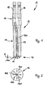
- a gripper 1 has a gripper head 10 with a bearing surface 100.
- a plurality of openings 101 are provided in the gripper head 10, as can best be seen from Fig. 2.
- the openings 101 are arranged on an arc of a circle, and an opening 102 is also arranged at the centre of the arc of the circle.
- a separate channel 103 is provided starting from the opening 102 at the centre of the arc of the circle and extending to each opening 101 on the arc of the circle (as it were in a star shape), which channel 103 connects the opening 102 at the centre to the respective opening 101 on the arc of the circle.
- the channels 103 are designed as grooves in the bearing surface 100, which are open at one side and extend radially outwards beyond the respective opening 101 on the arc of the circle. Openings 101 could for example also be connected to one another via a channel in the shape of an arc of a circle, but in the illustrative embodiment they are not shown.
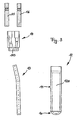
- the gripper 1 Adjoining the gripper head 10, the gripper 1 has a cylindrical part 11 which is formed integrally with the gripper head 10 and as a whole forms a part 12 which can be made for example of a plastic such as POM (polyoxymethylene).
- a tube 13 which can function as an underpressure channel and ends at a short distance d from the openings 101 and from the opening 102 at the centre.
- This distance d can be in the range of approximately 0.1 mm to approximately 5 mm and is preferably approximately 1 mm.
- the interior 120 itself can form an overpressure channel, as will be explained in more detail below in the description of how the illustrative embodiment of the gripper 1 according to the invention functions.
- the overpressure channel and the underpressure channel are thus separate from one another, and only at the end of the tube 13 in immediate proximity to the openings 101, 102 can this be otherwise.
- the attachment pieces 15 and 16, the adapter piece 14 and the part 12 with the cylindrical part 11 and with the gripper head 10 are shown as individual parts in Fig. 3, the gripper 1 in Fig. 1 is shown in its assembled state. From Fig. 3 it can be seen that all of the individual parts are easily produced lathed parts, so that the outlay required to produce the individual parts is relatively small, which fact would appear to constitute a further particular advantage of the gripper 1 according to the invention.
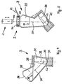
- the test cell 3 is here designed in such a way that it has a hollow space 31 which extends along a first axis 32, which, in the test position shown in Fig. 4, coincides with the optical axis of an inspection system (not shown here).
- the hollow space 31 is delimited from above by a viewing glass 33.
- the lower area of the hollow space 31 is designed as a test trough 34 in which the contact lens CL according to Fig. 4 is received in the test position.
- the test cell 3 is filled with a liquid, e.g. water, the level 38 of the liquid in the test position lying above the viewing glass 33 so that no free interface of the liquid can interfere with the image and so that no air bubbles are present between liquid and viewing glass 33.
- the insertion channel 35 extends in a substantially rectilinear manner along a second axis 37 which is at an angle of approximately 45° to the first axis 32 of the hollow space 31. Rectilinear is here intended to signify that a gripper 1 moving in a linear manner can pass through the insertion channel 35 into the hollow space 31 in order to deposit or remove a contact lens CL.
- the test cell 3 shown can be swivelled between a test position (Fig. 4) and a removal position (Fig. 5).
- the axis 37 of the insertion channel 35 runs vertically, so that the contact lens CL can be removed from above with the aid of the gripper 1 according to the invention.
- the gripper 1 is moved through a nozzle ring 2, whose function will be explained further below, and toward the contact lens CL which is located In a removal trough 39 when the test cell 3 is in the removal position (Fig. 5).
- an underpressure is applied and the contact lens CL is sucked against the bearing surface 100 of the gripper head 10.
- underpressure is applied via the tube 37 through all the openings 101 and 102, resulting in the contact lens CL being sucked up in a uniform and reliable manner.
- liquid in this case water, is also sucked up.
- the underpressure remains applied and the gripper 1, together with the contact lens CL which has been sucked onto the bearing surface 100, is again moved upwards out of the insertion channel 35.
- the gripper 1, together with the contact lens CL sucked onto the bearing surface 100 is moved through the nozzle ring 2 which here has nozzles 20 which face inwards from its inner wall and which are fed with a gaseous medium through a supply channel 21 provided in the nozzle ring 2.
- the nozzle ring 2 is provided with a blowing-air delivery means 22 through which blowing air (or another gaseous medium) is fed to the supply channel 21 and is then blown through the nozzles 20.
- the gripper 1 together with said contact lens CL sucked onto the bearing surface 100 of the gripper head 10, can be moved over the receptacle of a final package (not shown) Into which the contact lens CL is to be deposited. During this movement of the gripper 1 to the receptacle, liquid is sucked off the entire time so that extremely little liquid, preferably none at all, is entrained with the contact lens CL or with the gripper 1 into the receptacle.
- a receptacle in which a contact lens CL can be deposited and which forms part of a final package is described for example in EP-A-0 680 895 and has a receiving trough for the contact lens into which the contact lens is to be deposited with relatively precise positioning, so that the contact lens cannot be damaged when the receptacle is sealed with the aid of a cover foil.
- the gripper 1 is moved across the receiving trough of the receptacle.
- Overpressure is now applied via the overpressure channel, that is to say via the interior 120.
- the underpressure can at the same time be maintained in the tube 13 so that, as a result of simultaneously applied overpressure and underpressure, any liquid possibly still present in the interior 120 near the openings is forced by the overpressure in the direction towards the tube 13 and is sucked off there by the prevailing underpressure.
- the application of the underpressure can be ended so that only overpressure (e.g. blowing air) is applied.
- the overpressure applied through the openings 101 and 102 ensures that the contact lens CL lying on the bearing surface 100 of the gripper head 10 is released (blown off) from the bearing surface 100 of the gripper head 10 in a controlled and uniform manner, so that for example it is deposited in a controlled and precise manner into the receiving trough of the receptacle of the final package.
- the above-described use of the gripper according to the invention for removing a contact lens from a test cell and subsequently depositing the contact lens in the receptacle of a final package is to be seen only as an example of one possible use of the gripper.
- the gripper can of course also be used at other stations of an automated production process for contact lenses, for example for removing contact lenses from the female mould half, or at stations at which the contact lens has to be transferred for other reasons.
Abstract
Description
- The invention relates to a gripper according to the preamble of the independent patent claim.
- In the automated production of contact lenses in general, but especially In the production of large batches of contact lenses, as is the case for example with disposable lenses, it is necessary, at certain stations in the production process, to be able to manipulate the contact lenses safely, quickly and efficiently. An example of such manipulation of a contact lens is when the contact lens is removed from a test cell in which said contact lens has been placed in a liquid, for example in water, in order to test it (e.g. by image processing).
- To remove the tested contact lens from such a test cell, devices called grippers are used, as are also used at other stations in such a production process. The contact lens is gripped with the aid of such a gripper and, in the example described above, is removed from the test cell. The contact lens is then deposited for example into a receptacle which can be part of the final package for the contact lens and into which a storage solution (e.g. saline) is dispensed. The receptacle is then welded or sealed with a cover foil, and, after subsequent autoclaving, the final package can be released for distribution. EP-A- 1 136 241 and WO-A- 9 857 788 describe grippers for gripping contact lenses.
- In the above-described removal of the contact lens from the test cell and the subsequent dispensing of the contact lens into the receptacle in which the saline is present, care must be taken to ensure that only a very small amount of water, preferably none at all, is entrained with the contact lens. This is a problem which is not at all easy to solve, because the contact lens in the abovementioned test cell has to be sucked from "under water" (with the result that water is necessarily also sucked out with the lens), then transported to the receptacle which is part of the final package, and finally deposited in this receptacle, for which purpose the contact lens has to be released again from the gripper. In addition, the contact lens has to be gripped securely by the gripper (even "under water"), and in the case of small receptacles the contact lens has to be reliably deposited centrally in the receptacle so that it is not later damaged by the cover foil during the welding or sealing of the receptacle.
- The object of the present invention is to make available a gripper which is able to satisfy the abovementioned requirements, in other words one which, on the one hand, reliably grips a contact lens, if appropriate even "under water", and in such a case ensures that the amount of liquid (e.g. water) entrained is very small (e.g. less than approximately 40 microlitres). On the other hand, the contact lens must be able to be reliably deposited centrally in a receptacle, for which purpose it must be possible to achieve a highly controlled release of the contact lens from the gripper.
- This object is achieved by a gripper according to the invention, as characterized by the features of the independent patent claim. Particularly advantageous embodiments of the gripper according to the invention will become evident from the features of the dependent patent claims.
- In particular, the gripper according to the invention comprises a gripper head which has a bearing surface for a contact lens and in which one or more openings are provided through which an underpressure can be applied in order to suck the contact lens against the bearing surface, and through which an overpressure can be applied in order to release the contact lens from the bearing surface. Channels are provided in the gripper head which connect a plurality of openings to one another. By connecting a plurality of openings (possibly even all the openings) with the aid of channels provided in the gripper head, it is possible on the one hand, upon application of underpressure, to reliably suck the contact lens against the bearing surface of the gripper head, because the contact lens is sucked against the bearing surface at several positions simultaneously, and, on the other hand, it is possible, for the same reason, to ensure that, upon application of overpressure, the contact lens can be deposited safely and in a deliberate manner into a receptacle, e.g. centrally into a receptacle which forms part of a final package, as has already been described in the introduction.
- The channels can for example in this case be designed as (relatively narrow and fairly shallow) grooves. It is therefore possible to simultaneously apply underpressure or overpressure either through a plurality of the openings present or even through all the openings present and thereby to suck the contact lens against the bearing surface, or release it from the bearing surface, via all the openings simultaneously.
- If, as has been described above, the contact lens is for example situated in a test cell in which there is a liquid (e.g. water), the contact lens is sucked from "under water" in the gripping operation, and it can happen that liquid gets in between the rear face of the contact lens and the bearing surface of the gripper head. Such trapped liquid can now be sucked through the channels, with the contact lens lying against the bearing surface of the gripper head, as a result of which the amount of water entrained can be kept very small.
- A design of the gripper is advantageous in which the openings are arranged on an arc of a circle, and an opening is also arranged at the centre of the arc of the circle. In this design of the gripper, the contact lens can be sucked particularly reliably against the bearing surface of the gripper head, and a likewise reliable and deliberate release of the contact lens is also made possible. For this purpose, a separate channel can be provided starting from the opening at the centre of the arc of the circle and extending to each opening arranged on the arc of the circle (as it were in a star shape), said channel connecting the opening at the centre to the respective opening on the arc of the circle.
- Furthermore, it can be advantageous if the respective channel, which connects the opening at the centre of the arc of the circle to the respective opening on the arc of the circle, extends radially outwards beyond the opening on the arc of the circle. This ensures that, upon application of underpressure, air can always be reliably sucked in and, as a result, liquid can always be carried off, by which means the amount of water entrained can be kept very small.
- It is particularly advantageous if the channels connecting the openings to one another are provided in the bearing surface (against which a contact lens rests after being sucked up) because any liquid caught between the contact lens and the bearing surface can then be sucked off particularly easily.
- To ensure the least possible entrainment of liquid, the outer face of the gripper in a further advantageous embodiment is smooth and in particular has no depressions in which liquid can collect.
- In a further advantageous embodiment, the gripper according to the invention has an underpressure channel leading to the openings in the gripper head and has an overpressure channel likewise leading to the openings in the gripper head, said overpressure channel and said underpressure channel being essentially separate from one another. The essentially separate provision of an underpressure channel and of an overpressure channel makes it possible to apply only overpressure or to apply only underpressure, or even both. When depositing the contact lens, there may in fact, for example, still be water present in the interior of the gripper head, which water should be sucked off before the contact lens is deposited. To ensure that this water is not entrained into the receptacle in which the contact lens is deposited, both overpressure and underpressure can be applied for a short period of time, in which case the overpressure ensures that the water situated in the interior of the gripper head and still not sucked away is driven into the underpressure channel, so that, after this water has been sucked off, the contact lens can be released in a deliberate manner and smoothly from the bearing surface, and entrainment of this water is avoided.
- To this end, an embodiment of the gripper according to the invention can be advantageous in which the underpressure channel is formed by a tube which extends through the interior of the gripper forming the overpressure channel, and which ends at a short distance from the openings in the gripper head. The tube forming the underpressure channel can In this case end at a distance of 0.1 mm to 5 mm, preferably at a distance of approximately 1 mm, from the openings in the gripper head.
- The invention further relates to a grip device for contact lenses, with a gripper which has been described in one of the preceding embodiments, and with a nozzle ring which on its inner wall is provided with nozzles through which a gaseous medium, e.g. air, can be applied. The gripper and nozzle ring are designed such that the gripper can be moved through the nozzle ring towards a contact lens which is to be gripped and, after the contact lens has been gripped, can be moved back together with the contact lens through the nozzle ring again. As the gripper is moved back through the nozzle ring, the contact lens can be acted upon by the gaseous medium so that liquid (e.g. water) which Is attached to the outside of the contact lens can be blown off (if, for example, the nozzle ring is arranged over the above-described test cell, the blown-off liquid can even be caught again by the test cell) and the entrainment of liquid can thus be further reduced.
- Further advantageous configurations will become evident from the following description of an illustrative embodiment of the invention with reference to the drawing which shows diagrammatic representations and/or cross sections.
- Fig. 1 shows a view of an illustrative embodiment of a gripper according to the invention,
- Fig. 2shows a view of the bearing surface of the gripper from Fig. 1,
- Fig. 3shows a view of the individual parts of the gripper from Fig. 1,
- Fig. 4shows a test cell in a first position, In which a contact lens present in the test cell is tested,
and - Fig. 5 shows the test cell from Fig. 4 in a second position, in which the contact lens can be removed from the test cell with the aid of the gripper according to the invention, said gripper being guided through a nozzle ring which, together with the gripper, forms a grip device.
- The illustrative embodiment of a
gripper 1 according to the invention, explained below with reference to Figures 1-3, has agripper head 10 with abearing surface 100. A plurality ofopenings 101 are provided in thegripper head 10, as can best be seen from Fig. 2. In the illustrative embodiment shown here, theopenings 101 are arranged on an arc of a circle, and anopening 102 is also arranged at the centre of the arc of the circle. Aseparate channel 103 is provided starting from theopening 102 at the centre of the arc of the circle and extending to eachopening 101 on the arc of the circle (as it were in a star shape), whichchannel 103 connects theopening 102 at the centre to therespective opening 101 on the arc of the circle. Thechannels 103 are designed as grooves in thebearing surface 100, which are open at one side and extend radially outwards beyond therespective opening 101 on the arc of the circle.Openings 101 could for example also be connected to one another via a channel in the shape of an arc of a circle, but in the illustrative embodiment they are not shown. - Adjoining the
gripper head 10, thegripper 1 has acylindrical part 11 which is formed integrally with thegripper head 10 and as a whole forms apart 12 which can be made for example of a plastic such as POM (polyoxymethylene). Thegripper 1 as a whole, but in particular thepart 12, has a smooth surface without depressions in which liquid could gather and could then be entrained. - Extending through the
interior 120 of thepart 12 there is atube 13 which can function as an underpressure channel and ends at a short distance d from theopenings 101 and from theopening 102 at the centre. This distance d can be in the range of approximately 0.1 mm to approximately 5 mm and is preferably approximately 1 mm. Theinterior 120 itself can form an overpressure channel, as will be explained in more detail below in the description of how the illustrative embodiment of thegripper 1 according to the invention functions. The overpressure channel and the underpressure channel are thus separate from one another, and only at the end of thetube 13 in immediate proximity to theopenings - Adjoining the
cylindrical part 12 of thegripper 1 there is anadapter piece 14 which can be connected to thepart 12 and which has receivingbores 143 for thetube 13 and forcorresponding attachment pieces attachment pieces adapter piece 14 and thepart 12 with thecylindrical part 11 and with thegripper head 10 are shown as individual parts in Fig. 3, thegripper 1 in Fig. 1 is shown in its assembled state. From Fig. 3 it can be seen that all of the individual parts are easily produced lathed parts, so that the outlay required to produce the individual parts is relatively small, which fact would appear to constitute a further particular advantage of thegripper 1 according to the invention. - In order now to explain the manner in which the
gripper 1 functions, reference is made to the example mentioned at the outset, namely that of removing a contact lens CL from atest cell 3, and this will be explained in detail below with reference to Fig. 4 and Fig. 5. Thetest cell 3 is here designed in such a way that it has ahollow space 31 which extends along afirst axis 32, which, in the test position shown in Fig. 4, coincides with the optical axis of an inspection system (not shown here). Thehollow space 31 is delimited from above by a viewing glass 33. The lower area of thehollow space 31 is designed as atest trough 34 in which the contact lens CL according to Fig. 4 is received in the test position. Thetest cell 3 is filled with a liquid, e.g. water, thelevel 38 of the liquid in the test position lying above the viewing glass 33 so that no free interface of the liquid can interfere with the image and so that no air bubbles are present between liquid and viewing glass 33. - Opening into the
hollow space 31 there is aninsertion channel 35 which has anouter opening 36 through which the contact lens CL can be inserted into thehollow space 31, for example by means of thegripper 1 according to the invention. Theinsertion channel 35 extends in a substantially rectilinear manner along asecond axis 37 which is at an angle of approximately 45° to thefirst axis 32 of thehollow space 31. Rectilinear is here intended to signify that agripper 1 moving in a linear manner can pass through theinsertion channel 35 into thehollow space 31 in order to deposit or remove a contact lens CL. - As can be seen from a comparison of Fig. 4 and Fig. 5, the
test cell 3 shown can be swivelled between a test position (Fig. 4) and a removal position (Fig. 5). In the removal position of thetest cell 3 shown in Fig. 5, theaxis 37 of theinsertion channel 35 runs vertically, so that the contact lens CL can be removed from above with the aid of thegripper 1 according to the invention. - For this purpose, the
gripper 1 is moved through anozzle ring 2, whose function will be explained further below, and toward the contact lens CL which is located In aremoval trough 39 when thetest cell 3 is in the removal position (Fig. 5). Once thegripper 1 has reached the contact lens CL, an underpressure is applied and the contact lens CL is sucked against the bearingsurface 100 of thegripper head 10. To suck the contact lens CL, underpressure is applied via thetube 37 through all theopenings - The underpressure remains applied and the
gripper 1, together with the contact lens CL which has been sucked onto the bearingsurface 100, is again moved upwards out of theinsertion channel 35. In doing so, thegripper 1, together with the contact lens CL sucked onto the bearingsurface 100, is moved through thenozzle ring 2 which here hasnozzles 20 which face inwards from its inner wall and which are fed with a gaseous medium through asupply channel 21 provided in thenozzle ring 2. Thenozzle ring 2 is provided with a blowing-air delivery means 22 through which blowing air (or another gaseous medium) is fed to thesupply channel 21 and is then blown through thenozzles 20. - When the
gripper 1, together with the contact lens CL sucked onto the bearingsurface 100, passes through thenozzle ring 2, liquid attached to the outside of the contact lens CL is blown off from the contact lens CL with the aid of the blowing air emerging from thenozzles 20. In the illustrated arrangement of thenozzle ring 2 directly above thetest cell 3, the blown-off liquid can be caught by thetest cell 3. This particular arrangement of thenozzle ring 2 is advantageous, but it is not obligatory, because, in the case of a minor entrainment of liquid (in this case water), it is not imperative that the liquid blown off from the contact lens CL is caught by thetest cell 3. - If water is trapped between the contact lens CL and the
bearing surface 100 of the gripper head 10 (as can quite easily happen when the contact lens is sucked onto the surface), this water, with the contact lens CL sucked onto the surface, can pass through the channels 103 (grooves) in thebearing surface 100 to theopenings tube 13. The distance d of the end of thetube 37 from the openings is therefore chosen so that the liquid which passes through theopenings - After the contact lens CL has been removed from the
test cell 3, thegripper 1, together with said contact lens CL sucked onto the bearingsurface 100 of thegripper head 10, can be moved over the receptacle of a final package (not shown) Into which the contact lens CL is to be deposited. During this movement of thegripper 1 to the receptacle, liquid is sucked off the entire time so that extremely little liquid, preferably none at all, is entrained with the contact lens CL or with thegripper 1 into the receptacle. A receptacle in which a contact lens CL can be deposited and which forms part of a final package is described for example in EP-A-0 680 895 and has a receiving trough for the contact lens into which the contact lens is to be deposited with relatively precise positioning, so that the contact lens cannot be damaged when the receptacle is sealed with the aid of a cover foil. - To deposit the contact lens in the receiving trough of the receptacle, the
gripper 1 is moved across the receiving trough of the receptacle. Overpressure is now applied via the overpressure channel, that is to say via theinterior 120. In doing so, the underpressure can at the same time be maintained in thetube 13 so that, as a result of simultaneously applied overpressure and underpressure, any liquid possibly still present in the interior 120 near the openings is forced by the overpressure in the direction towards thetube 13 and is sucked off there by the prevailing underpressure. After a certain period of time has elapsed, the application of the underpressure can be ended so that only overpressure (e.g. blowing air) is applied. The overpressure applied through theopenings bearing surface 100 of thegripper head 10 is released (blown off) from the bearingsurface 100 of thegripper head 10 in a controlled and uniform manner, so that for example it is deposited in a controlled and precise manner into the receiving trough of the receptacle of the final package. - The above-described use of the gripper according to the invention for removing a contact lens from a test cell and subsequently depositing the contact lens in the receptacle of a final package is to be seen only as an example of one possible use of the gripper. The gripper can of course also be used at other stations of an automated production process for contact lenses, for example for removing contact lenses from the female mould half, or at stations at which the contact lens has to be transferred for other reasons.
Claims (11)
- Gripper (1) for contact lenses, with a gripper head (10) which has a bearing surface (100) for a contact lens (CL) and in which one or more openings (101,102) are provided through which an underpressure can be applied in order to suck the contact lens (CL) against the bearing surface (100), and through which an overpressure can be applied in order to release the contact lens (CL) from the bearing surface (100), characterized in that channels (103) are provided in the gripper head (10) and connect a plurality of openings (101, 102) to one another.
- Gripper according to Claim 1, characterized in that the channels (103) are designed as grooves.
- Gripper according to either of Claims 1 and 2, characterized in that the openings (101) are arranged on an arc of a circle, and an opening (102) is also arranged at the centre of the arc of the circle.
- Gripper according to Claim 3, characterized in that a separate channel (103) is provided starting from the opening (102) at the centre of the arc of the circle and extending to each opening (101) arranged on the arc of the circle, said channel (103) connecting the opening (102) at the centre to the respective opening (101) on the arc of the circle.
- Gripper according to Claim 4, characterized in that the respective channel (103), which connects the opening (102) at the centre of the arc of the circle to the respective opening (101) on the arc of the circle, extends radially outwards beyond the opening (101) on the arc of the circle.
- Gripper according to one of Claims 1 to 5, characterized in that the channels (103) are provided in the bearing surface (100).
- Gripper according to one of the preceding claims, characterized in that the outer surface of the gripper (1) is smooth and in particular has no depressions in which liquid can collect.
- Gripper according to one of the preceding claims, characterized in that it has an underpressure channel (13) leading to the openings (101, 102) in the gripper head (10) and has an overpressure channel (120) likewise leading to the openings (1010, 102) in the gripper head (10), said overpressure channel (120) and said underpressure channel (13) being essentially separate from one another.
- Gripper according to Claim 8, characterized in that the underpressure channel (13) is formed by a tube which extends through the interior of the gripper (1) forming the overpressure channel (120), and which ends at a short distance (d) from the openings (101, 102) in the gripper head (10).
- Gripper according to Claim 9, characterized in that the tube forming the underpressure channel (13) ends at a distance (d) of 0.1 mm to 5 mm, preferably at a distance of approximately 1 mm, from the openings (101, 102) in the gripper head (10).
- Grip device for contact lenses, with a gripper (1) according to one of the preceding claims, and with a nozzle ring (2) which on its inner wall is provided with nozzles (20) through which a gaseous medium, e.g. air, can be applied, said gripper (1) and nozzle ring (2) being designed such that the gripper (1) can be moved through the nozzle ring (2) towards a contact lens (CL) which is to be gripped and, after the contact lens (CL) has been gripped, can be moved back together with the contact lens (CL) through the nozzle ring (2) again so that, as the gripper (1) is moved back through the nozzle ring (2), the contact lens (CL) can be acted upon by the gaseous medium.
Priority Applications (1)
| Application Number | Priority Date | Filing Date | Title |
|---|---|---|---|
| EP03714861A EP1490209B1 (en) | 2002-03-21 | 2003-03-20 | Gripper |
Applications Claiming Priority (4)
| Application Number | Priority Date | Filing Date | Title |
|---|---|---|---|
| EP02006341 | 2002-03-21 | ||
| EP02006341 | 2002-03-21 | ||
| PCT/EP2003/002919 WO2003080320A1 (en) | 2002-03-21 | 2003-03-20 | Gripper |
| EP03714861A EP1490209B1 (en) | 2002-03-21 | 2003-03-20 | Gripper |
Publications (2)
| Publication Number | Publication Date |
|---|---|
| EP1490209A1 EP1490209A1 (en) | 2004-12-29 |
| EP1490209B1 true EP1490209B1 (en) | 2006-01-25 |
Family
ID=27838024
Family Applications (1)
| Application Number | Title | Priority Date | Filing Date |
|---|---|---|---|
| EP03714861A Expired - Lifetime EP1490209B1 (en) | 2002-03-21 | 2003-03-20 | Gripper |
Country Status (7)
| Country | Link |
|---|---|
| US (1) | US6994386B2 (en) |
| EP (1) | EP1490209B1 (en) |
| JP (1) | JP4330451B2 (en) |
| AT (1) | ATE316459T1 (en) |
| AU (1) | AU2003219087A1 (en) |
| DE (1) | DE60303367T2 (en) |
| WO (1) | WO2003080320A1 (en) |
Cited By (1)
| Publication number | Priority date | Publication date | Assignee | Title |
|---|---|---|---|---|
| WO2008012152A1 (en) * | 2006-06-26 | 2008-01-31 | Novartis Ag | Method and device for singulating ophthalmic lenses |
Families Citing this family (16)
| Publication number | Priority date | Publication date | Assignee | Title |
|---|---|---|---|---|
| MY140797A (en) * | 2005-05-13 | 2010-01-15 | Novartis Ag | Gripper for moving and positioning contact lenses |
| ES2318932B1 (en) | 2006-01-23 | 2010-02-09 | Fundacion Fatronik | MACHINE FOR SHEET CONFORMING AND CONFORMING PROCEDURE. |
| WO2008000417A1 (en) * | 2006-06-26 | 2008-01-03 | Novartis Ag | Method and apparatus for cleaning of ophthalmic lenses |
| EP1927409A1 (en) * | 2006-11-30 | 2008-06-04 | Bausch & Lomb Incorporated | Method for handling contact lens |
| US8290624B2 (en) | 2007-04-26 | 2012-10-16 | Adept Technology, Inc. | Uniform lighting and gripper positioning system for robotic picking operations |
| HUE038990T2 (en) * | 2009-09-04 | 2018-12-28 | Novartis Ag | Gripper for a contact lens and process for transporting a contact lens |
| US9296160B2 (en) * | 2009-09-11 | 2016-03-29 | Coopervision International Holding Company, Lp | Method for moving wet ophthalmic lenses during their manufacture |
| MY172882A (en) * | 2009-10-16 | 2019-12-13 | Alcon Inc | Method and device for removing a contact lens from a container |
| MY159407A (en) | 2010-11-19 | 2016-12-30 | Novartis Ag | Gripper for grasping an ophthalmic lens immersed in a liquid |
| EP2602099B1 (en) * | 2011-12-08 | 2014-02-12 | Harro Höfliger Verpackungsmaschinen GmbH | Vacuum gripper and handling system for contact lenses |
| KR102127820B1 (en) * | 2013-08-28 | 2020-06-29 | 삼성전기주식회사 | Lens demolding device and the lens demolding method |
| KR102139754B1 (en) | 2013-09-27 | 2020-07-31 | 삼성전기주식회사 | Lens demolding system and the lens demolding method |
| USD829778S1 (en) * | 2016-06-27 | 2018-10-02 | Ngk Spark Plug Co. Ltd. | Vacuum chuck |
| SG11202102473YA (en) | 2018-10-25 | 2021-05-28 | Alcon Inc | Gripper for an ophthalmic contact lens and process for transporting an ophthalmic contact lens |
| WO2021144738A1 (en) | 2020-01-16 | 2021-07-22 | Alcon Inc. | Cleaner for cleaning grippers for ophthalmic lenses |
| WO2022107004A1 (en) * | 2020-11-17 | 2022-05-27 | Alcon Inc. | Mold unit for molding ophthalmic lenses |
Family Cites Families (10)
| Publication number | Priority date | Publication date | Assignee | Title |
|---|---|---|---|---|
| US3134208A (en) * | 1962-01-08 | 1964-05-26 | Clyde S Mccain | Lens holding device |
| US3879076A (en) * | 1973-12-27 | 1975-04-22 | Robert O Barnett | Method and apparatus for applying and removing a soft contact lens |
| ES2183383T3 (en) | 1997-06-19 | 2003-03-16 | Bausch & Lomb | TRANSFER AND CENTER SYSTEM FOR CONTACT LENSES. |
| US6032997A (en) * | 1998-04-16 | 2000-03-07 | Excimer Laser Systems | Vacuum chuck |
| US6254155B1 (en) * | 1999-01-11 | 2001-07-03 | Strasbaugh, Inc. | Apparatus and method for reliably releasing wet, thin wafers |
| US6494021B1 (en) * | 1999-02-18 | 2002-12-17 | Johnson & Johnson Vision Care, Inc. | Contact lens transfer and material removal system |
| US6279976B1 (en) * | 1999-05-13 | 2001-08-28 | Micron Technology, Inc. | Wafer handling device having conforming perimeter seal |
| EP1136241B1 (en) * | 2000-03-16 | 2006-06-21 | Novartis AG | Apparatus for the removal of contact lenses |
| JP4634629B2 (en) | 2000-03-16 | 2011-02-16 | ノバルティス アーゲー | Contact lens removal device |
| US6398277B1 (en) * | 2001-03-15 | 2002-06-04 | Mcdonald Marguerite B. | Contact lens insertion device |
-
2003
- 2003-03-12 US US10/386,951 patent/US6994386B2/en not_active Expired - Lifetime
- 2003-03-20 WO PCT/EP2003/002919 patent/WO2003080320A1/en active IP Right Grant
- 2003-03-20 DE DE60303367T patent/DE60303367T2/en not_active Expired - Lifetime
- 2003-03-20 AT AT03714861T patent/ATE316459T1/en not_active IP Right Cessation
- 2003-03-20 JP JP2003578126A patent/JP4330451B2/en not_active Expired - Fee Related
- 2003-03-20 EP EP03714861A patent/EP1490209B1/en not_active Expired - Lifetime
- 2003-03-20 AU AU2003219087A patent/AU2003219087A1/en not_active Abandoned
Cited By (2)
| Publication number | Priority date | Publication date | Assignee | Title |
|---|---|---|---|---|
| WO2008012152A1 (en) * | 2006-06-26 | 2008-01-31 | Novartis Ag | Method and device for singulating ophthalmic lenses |
| CN101479173B (en) * | 2006-06-26 | 2012-09-19 | 诺瓦提斯公司 | Method and device for singulating ophthalmic lenses |
Also Published As
| Publication number | Publication date |
|---|---|
| AU2003219087A1 (en) | 2003-10-08 |
| WO2003080320A1 (en) | 2003-10-02 |
| DE60303367T2 (en) | 2006-10-26 |
| US20030178862A1 (en) | 2003-09-25 |
| US6994386B2 (en) | 2006-02-07 |
| JP2005520714A (en) | 2005-07-14 |
| EP1490209A1 (en) | 2004-12-29 |
| DE60303367D1 (en) | 2006-04-13 |
| JP4330451B2 (en) | 2009-09-16 |
| ATE316459T1 (en) | 2006-02-15 |
Similar Documents
| Publication | Publication Date | Title |
|---|---|---|
| EP1490209B1 (en) | Gripper | |
| KR100709906B1 (en) | Contact lens transfer and material removal system | |
| EP2473338B1 (en) | Gripper for a contact lens and process for transporting a contact lens | |
| US9272424B2 (en) | Gripper for a contact lens and process for transporting a contact lens | |
| EP2640568B1 (en) | Gripper for grasping an ophthalmic lens immersed in a liquid | |
| HUH3772A (en) | Holder for hydrating contact lenses and holder for placing contact lenses in package | |
| US7789266B2 (en) | Method and device for singulating ophthalmic lenses | |
| US20040074525A1 (en) | Transfer apparatus and method and a transfer apparatus cleaner and method | |
| US9796145B2 (en) | Apparatus for removing an ophthalmic lens from a mold half | |
| EP1910798B1 (en) | Method and apparatus for centering an ophthalmic lens | |
| CN117140848B (en) | Continuous forming production line and forming process of degerming filter membrane component in liquid dropper | |
| JPH09295357A (en) | Apparatus for feeding contact lens and method therefor |
Legal Events
| Date | Code | Title | Description |
|---|---|---|---|
| PUAI | Public reference made under article 153(3) epc to a published international application that has entered the european phase |
Free format text: ORIGINAL CODE: 0009012 |
|
| 17P | Request for examination filed |
Effective date: 20041021 |
|
| AK | Designated contracting states |
Kind code of ref document: A1 Designated state(s): AT BE BG CH CY CZ DE DK EE ES FI FR GB GR HU IE IT LI LU MC NL PT RO SE SI SK TR |
|
| AX | Request for extension of the european patent |
Extension state: AL LT LV MK |
|
| GRAP | Despatch of communication of intention to grant a patent |
Free format text: ORIGINAL CODE: EPIDOSNIGR1 |
|
| GRAS | Grant fee paid |
Free format text: ORIGINAL CODE: EPIDOSNIGR3 |
|
| GRAA | (expected) grant |
Free format text: ORIGINAL CODE: 0009210 |
|
| AK | Designated contracting states |
Kind code of ref document: B1 Designated state(s): AT BE BG CH CY CZ DE DK EE ES FI FR GB GR HU IE IT LI LU MC NL PT RO SE SI SK TR |
|
| PG25 | Lapsed in a contracting state [announced via postgrant information from national office to epo] |
Ref country code: NL Free format text: LAPSE BECAUSE OF FAILURE TO SUBMIT A TRANSLATION OF THE DESCRIPTION OR TO PAY THE FEE WITHIN THE PRESCRIBED TIME-LIMIT Effective date: 20060125 Ref country code: SI Free format text: LAPSE BECAUSE OF FAILURE TO SUBMIT A TRANSLATION OF THE DESCRIPTION OR TO PAY THE FEE WITHIN THE PRESCRIBED TIME-LIMIT Effective date: 20060125 Ref country code: LI Free format text: LAPSE BECAUSE OF FAILURE TO SUBMIT A TRANSLATION OF THE DESCRIPTION OR TO PAY THE FEE WITHIN THE PRESCRIBED TIME-LIMIT Effective date: 20060125 Ref country code: IT Free format text: LAPSE BECAUSE OF FAILURE TO SUBMIT A TRANSLATION OF THE DESCRIPTION OR TO PAY THE FEE WITHIN THE PRESCRIBED TIME-LIMIT;WARNING: LAPSES OF ITALIAN PATENTS WITH EFFECTIVE DATE BEFORE 2007 MAY HAVE OCCURRED AT ANY TIME BEFORE 2007. THE CORRECT EFFECTIVE DATE MAY BE DIFFERENT FROM THE ONE RECORDED. Effective date: 20060125 Ref country code: AT Free format text: LAPSE BECAUSE OF FAILURE TO SUBMIT A TRANSLATION OF THE DESCRIPTION OR TO PAY THE FEE WITHIN THE PRESCRIBED TIME-LIMIT Effective date: 20060125 Ref country code: CH Free format text: LAPSE BECAUSE OF FAILURE TO SUBMIT A TRANSLATION OF THE DESCRIPTION OR TO PAY THE FEE WITHIN THE PRESCRIBED TIME-LIMIT Effective date: 20060125 Ref country code: SK Free format text: LAPSE BECAUSE OF FAILURE TO SUBMIT A TRANSLATION OF THE DESCRIPTION OR TO PAY THE FEE WITHIN THE PRESCRIBED TIME-LIMIT Effective date: 20060125 Ref country code: BE Free format text: LAPSE BECAUSE OF FAILURE TO SUBMIT A TRANSLATION OF THE DESCRIPTION OR TO PAY THE FEE WITHIN THE PRESCRIBED TIME-LIMIT Effective date: 20060125 Ref country code: RO Free format text: LAPSE BECAUSE OF FAILURE TO SUBMIT A TRANSLATION OF THE DESCRIPTION OR TO PAY THE FEE WITHIN THE PRESCRIBED TIME-LIMIT Effective date: 20060125 Ref country code: FI Free format text: LAPSE BECAUSE OF FAILURE TO SUBMIT A TRANSLATION OF THE DESCRIPTION OR TO PAY THE FEE WITHIN THE PRESCRIBED TIME-LIMIT Effective date: 20060125 |
|
| REG | Reference to a national code |
Ref country code: GB Ref legal event code: FG4D |
|
| REG | Reference to a national code |
Ref country code: CH Ref legal event code: EP |
|
| REG | Reference to a national code |
Ref country code: IE Ref legal event code: FG4D |
|
| PG25 | Lapsed in a contracting state [announced via postgrant information from national office to epo] |
Ref country code: MC Free format text: LAPSE BECAUSE OF NON-PAYMENT OF DUE FEES Effective date: 20060331 Ref country code: LU Free format text: LAPSE BECAUSE OF NON-PAYMENT OF DUE FEES Effective date: 20060331 |
|
| REF | Corresponds to: |
Ref document number: 60303367 Country of ref document: DE Date of ref document: 20060413 Kind code of ref document: P |
|
| PG25 | Lapsed in a contracting state [announced via postgrant information from national office to epo] |
Ref country code: DK Free format text: LAPSE BECAUSE OF FAILURE TO SUBMIT A TRANSLATION OF THE DESCRIPTION OR TO PAY THE FEE WITHIN THE PRESCRIBED TIME-LIMIT Effective date: 20060425 Ref country code: BG Free format text: LAPSE BECAUSE OF FAILURE TO SUBMIT A TRANSLATION OF THE DESCRIPTION OR TO PAY THE FEE WITHIN THE PRESCRIBED TIME-LIMIT Effective date: 20060425 Ref country code: SE Free format text: LAPSE BECAUSE OF FAILURE TO SUBMIT A TRANSLATION OF THE DESCRIPTION OR TO PAY THE FEE WITHIN THE PRESCRIBED TIME-LIMIT Effective date: 20060425 |
|
| PG25 | Lapsed in a contracting state [announced via postgrant information from national office to epo] |
Ref country code: ES Free format text: LAPSE BECAUSE OF FAILURE TO SUBMIT A TRANSLATION OF THE DESCRIPTION OR TO PAY THE FEE WITHIN THE PRESCRIBED TIME-LIMIT Effective date: 20060506 |
|
| PG25 | Lapsed in a contracting state [announced via postgrant information from national office to epo] |
Ref country code: PT Free format text: LAPSE BECAUSE OF FAILURE TO SUBMIT A TRANSLATION OF THE DESCRIPTION OR TO PAY THE FEE WITHIN THE PRESCRIBED TIME-LIMIT Effective date: 20060626 |
|
| NLV1 | Nl: lapsed or annulled due to failure to fulfill the requirements of art. 29p and 29m of the patents act | ||
| REG | Reference to a national code |
Ref country code: CH Ref legal event code: PL |
|
| ET | Fr: translation filed | ||
| PLBE | No opposition filed within time limit |
Free format text: ORIGINAL CODE: 0009261 |
|
| STAA | Information on the status of an ep patent application or granted ep patent |
Free format text: STATUS: NO OPPOSITION FILED WITHIN TIME LIMIT |
|
| 26N | No opposition filed |
Effective date: 20061026 |
|
| PG25 | Lapsed in a contracting state [announced via postgrant information from national office to epo] |
Ref country code: GR Free format text: LAPSE BECAUSE OF FAILURE TO SUBMIT A TRANSLATION OF THE DESCRIPTION OR TO PAY THE FEE WITHIN THE PRESCRIBED TIME-LIMIT Effective date: 20060426 Ref country code: CZ Free format text: LAPSE BECAUSE OF FAILURE TO SUBMIT A TRANSLATION OF THE DESCRIPTION OR TO PAY THE FEE WITHIN THE PRESCRIBED TIME-LIMIT Effective date: 20060125 |
|
| PG25 | Lapsed in a contracting state [announced via postgrant information from national office to epo] |
Ref country code: EE Free format text: LAPSE BECAUSE OF FAILURE TO SUBMIT A TRANSLATION OF THE DESCRIPTION OR TO PAY THE FEE WITHIN THE PRESCRIBED TIME-LIMIT Effective date: 20060125 |
|
| PG25 | Lapsed in a contracting state [announced via postgrant information from national office to epo] |
Ref country code: TR Free format text: LAPSE BECAUSE OF FAILURE TO SUBMIT A TRANSLATION OF THE DESCRIPTION OR TO PAY THE FEE WITHIN THE PRESCRIBED TIME-LIMIT Effective date: 20060125 Ref country code: HU Free format text: LAPSE BECAUSE OF FAILURE TO SUBMIT A TRANSLATION OF THE DESCRIPTION OR TO PAY THE FEE WITHIN THE PRESCRIBED TIME-LIMIT Effective date: 20060726 |
|
| PG25 | Lapsed in a contracting state [announced via postgrant information from national office to epo] |
Ref country code: CY Free format text: LAPSE BECAUSE OF FAILURE TO SUBMIT A TRANSLATION OF THE DESCRIPTION OR TO PAY THE FEE WITHIN THE PRESCRIBED TIME-LIMIT Effective date: 20060125 |
|
| PGFP | Annual fee paid to national office [announced via postgrant information from national office to epo] |
Ref country code: FR Payment date: 20100324 Year of fee payment: 8 |
|
| REG | Reference to a national code |
Ref country code: FR Ref legal event code: ST Effective date: 20111130 |
|
| PG25 | Lapsed in a contracting state [announced via postgrant information from national office to epo] |
Ref country code: FR Free format text: LAPSE BECAUSE OF NON-PAYMENT OF DUE FEES Effective date: 20110331 |
|
| REG | Reference to a national code |
Ref country code: DE Ref legal event code: R082 Ref document number: 60303367 Country of ref document: DE Representative=s name: PFENNING, MEINIG & PARTNER MBB PATENTANWAELTE, DE Ref country code: DE Ref legal event code: R081 Ref document number: 60303367 Country of ref document: DE Owner name: ALCON INC., CH Free format text: FORMER OWNER: NOVARTIS AG, 4056 BASEL, CH |
|
| REG | Reference to a national code |
Ref country code: GB Ref legal event code: 732E Free format text: REGISTERED BETWEEN 20200123 AND 20200129 |
|
| PGFP | Annual fee paid to national office [announced via postgrant information from national office to epo] |
Ref country code: IE Payment date: 20220223 Year of fee payment: 20 Ref country code: GB Payment date: 20220217 Year of fee payment: 20 Ref country code: DE Payment date: 20220223 Year of fee payment: 20 |
|
| REG | Reference to a national code |
Ref country code: DE Ref legal event code: R071 Ref document number: 60303367 Country of ref document: DE |
|
| REG | Reference to a national code |
Ref country code: GB Ref legal event code: PE20 Expiry date: 20230319 |
|
| REG | Reference to a national code |
Ref country code: IE Ref legal event code: MK9A |
|
| PG25 | Lapsed in a contracting state [announced via postgrant information from national office to epo] |
Ref country code: GB Free format text: LAPSE BECAUSE OF EXPIRATION OF PROTECTION Effective date: 20230319 |
|
| P01 | Opt-out of the competence of the unified patent court (upc) registered |
Effective date: 20230504 |
|
| PG25 | Lapsed in a contracting state [announced via postgrant information from national office to epo] |
Ref country code: IE Free format text: LAPSE BECAUSE OF EXPIRATION OF PROTECTION Effective date: 20230320 |