JP4329135B2 - Printer device - Google Patents
Printer device Download PDFInfo
- Publication number
- JP4329135B2 JP4329135B2 JP22339498A JP22339498A JP4329135B2 JP 4329135 B2 JP4329135 B2 JP 4329135B2 JP 22339498 A JP22339498 A JP 22339498A JP 22339498 A JP22339498 A JP 22339498A JP 4329135 B2 JP4329135 B2 JP 4329135B2
- Authority
- JP
- Japan
- Prior art keywords
- image data
- image
- unit
- data
- Prior art date
- Legal status (The legal status is an assumption and is not a legal conclusion. Google has not performed a legal analysis and makes no representation as to the accuracy of the status listed.)
- Expired - Fee Related
Links
- 238000012545 processing Methods 0.000 claims description 425
- 238000000034 method Methods 0.000 claims description 329
- 230000008569 process Effects 0.000 claims description 240
- 238000012937 correction Methods 0.000 claims description 231
- 238000006243 chemical reaction Methods 0.000 claims description 80
- 238000003702 image correction Methods 0.000 claims description 38
- 230000015654 memory Effects 0.000 description 58
- 230000006870 function Effects 0.000 description 31
- 238000010586 diagram Methods 0.000 description 18
- 230000002829 reductive effect Effects 0.000 description 18
- 230000008859 change Effects 0.000 description 16
- 230000007246 mechanism Effects 0.000 description 15
- 230000004913 activation Effects 0.000 description 11
- 235000019646 color tone Nutrition 0.000 description 10
- 230000002441 reversible effect Effects 0.000 description 10
- 238000004364 calculation method Methods 0.000 description 8
- 239000004973 liquid crystal related substance Substances 0.000 description 8
- 238000007906 compression Methods 0.000 description 7
- 230000006835 compression Effects 0.000 description 7
- 230000002457 bidirectional effect Effects 0.000 description 6
- 239000000203 mixture Substances 0.000 description 6
- 230000002093 peripheral effect Effects 0.000 description 6
- 230000004044 response Effects 0.000 description 6
- 238000009826 distribution Methods 0.000 description 5
- 230000007613 environmental effect Effects 0.000 description 5
- 238000000605 extraction Methods 0.000 description 5
- 238000012546 transfer Methods 0.000 description 5
- 230000002159 abnormal effect Effects 0.000 description 4
- 239000003086 colorant Substances 0.000 description 4
- 238000004042 decolorization Methods 0.000 description 4
- 230000006866 deterioration Effects 0.000 description 4
- 230000009467 reduction Effects 0.000 description 4
- 230000015572 biosynthetic process Effects 0.000 description 3
- 244000145845 chattering Species 0.000 description 3
- 230000003247 decreasing effect Effects 0.000 description 3
- 230000000873 masking effect Effects 0.000 description 3
- 230000003287 optical effect Effects 0.000 description 3
- 238000003786 synthesis reaction Methods 0.000 description 3
- 230000005540 biological transmission Effects 0.000 description 2
- 230000006837 decompression Effects 0.000 description 2
- 230000000694 effects Effects 0.000 description 2
- 238000009434 installation Methods 0.000 description 2
- 239000000463 material Substances 0.000 description 2
- 238000003672 processing method Methods 0.000 description 2
- 229910052709 silver Inorganic materials 0.000 description 2
- 239000004332 silver Substances 0.000 description 2
- -1 silver halide Chemical class 0.000 description 2
- GGCZERPQGJTIQP-UHFFFAOYSA-N sodium;9,10-dioxoanthracene-2-sulfonic acid Chemical compound [Na+].C1=CC=C2C(=O)C3=CC(S(=O)(=O)O)=CC=C3C(=O)C2=C1 GGCZERPQGJTIQP-UHFFFAOYSA-N 0.000 description 2
- 230000003595 spectral effect Effects 0.000 description 2
- 238000003860 storage Methods 0.000 description 2
- 238000000859 sublimation Methods 0.000 description 2
- 230000008022 sublimation Effects 0.000 description 2
- 238000010521 absorption reaction Methods 0.000 description 1
- 230000002411 adverse Effects 0.000 description 1
- 230000003139 buffering effect Effects 0.000 description 1
- 238000004891 communication Methods 0.000 description 1
- 230000000295 complement effect Effects 0.000 description 1
- 239000012141 concentrate Substances 0.000 description 1
- 238000012790 confirmation Methods 0.000 description 1
- 238000007796 conventional method Methods 0.000 description 1
- 230000008878 coupling Effects 0.000 description 1
- 238000010168 coupling process Methods 0.000 description 1
- 238000005859 coupling reaction Methods 0.000 description 1
- 238000013144 data compression Methods 0.000 description 1
- 238000001514 detection method Methods 0.000 description 1
- 238000011161 development Methods 0.000 description 1
- 238000009792 diffusion process Methods 0.000 description 1
- 239000000284 extract Substances 0.000 description 1
- 238000009499 grossing Methods 0.000 description 1
- 238000005286 illumination Methods 0.000 description 1
- 230000002427 irreversible effect Effects 0.000 description 1
- 238000012423 maintenance Methods 0.000 description 1
- 230000008531 maintenance mechanism Effects 0.000 description 1
- 230000007257 malfunction Effects 0.000 description 1
- 238000002156 mixing Methods 0.000 description 1
- 238000002360 preparation method Methods 0.000 description 1
- 238000003825 pressing Methods 0.000 description 1
- 230000000717 retained effect Effects 0.000 description 1
- 230000035945 sensitivity Effects 0.000 description 1
- 230000001360 synchronised effect Effects 0.000 description 1
- 230000002194 synthesizing effect Effects 0.000 description 1
- 230000000007 visual effect Effects 0.000 description 1
- 230000003936 working memory Effects 0.000 description 1
Images


Classifications
-
- H—ELECTRICITY
- H04—ELECTRIC COMMUNICATION TECHNIQUE
- H04N—PICTORIAL COMMUNICATION, e.g. TELEVISION
- H04N1/00—Scanning, transmission or reproduction of documents or the like, e.g. facsimile transmission; Details thereof
- H04N1/00002—Diagnosis, testing or measuring; Detecting, analysing or monitoring not otherwise provided for
- H04N1/00005—Diagnosis, testing or measuring; Detecting, analysing or monitoring not otherwise provided for relating to image data
-
- H—ELECTRICITY
- H04—ELECTRIC COMMUNICATION TECHNIQUE
- H04N—PICTORIAL COMMUNICATION, e.g. TELEVISION
- H04N1/00—Scanning, transmission or reproduction of documents or the like, e.g. facsimile transmission; Details thereof
- H04N1/00002—Diagnosis, testing or measuring; Detecting, analysing or monitoring not otherwise provided for
- H04N1/00026—Methods therefor
- H04N1/00037—Detecting, i.e. determining the occurrence of a predetermined state
-
- H—ELECTRICITY
- H04—ELECTRIC COMMUNICATION TECHNIQUE
- H04N—PICTORIAL COMMUNICATION, e.g. TELEVISION
- H04N1/00—Scanning, transmission or reproduction of documents or the like, e.g. facsimile transmission; Details thereof
- H04N1/00002—Diagnosis, testing or measuring; Detecting, analysing or monitoring not otherwise provided for
- H04N1/00071—Diagnosis, testing or measuring; Detecting, analysing or monitoring not otherwise provided for characterised by the action taken
- H04N1/00082—Adjusting or controlling
-
- H—ELECTRICITY
- H04—ELECTRIC COMMUNICATION TECHNIQUE
- H04N—PICTORIAL COMMUNICATION, e.g. TELEVISION
- H04N1/00—Scanning, transmission or reproduction of documents or the like, e.g. facsimile transmission; Details thereof
- H04N1/00127—Connection or combination of a still picture apparatus with another apparatus, e.g. for storage, processing or transmission of still picture signals or of information associated with a still picture
- H04N1/00132—Connection or combination of a still picture apparatus with another apparatus, e.g. for storage, processing or transmission of still picture signals or of information associated with a still picture in a digital photofinishing system, i.e. a system where digital photographic images undergo typical photofinishing processing, e.g. printing ordering
- H04N1/00135—Scanning of a photographic original
-
- H—ELECTRICITY
- H04—ELECTRIC COMMUNICATION TECHNIQUE
- H04N—PICTORIAL COMMUNICATION, e.g. TELEVISION
- H04N1/00—Scanning, transmission or reproduction of documents or the like, e.g. facsimile transmission; Details thereof
- H04N1/00127—Connection or combination of a still picture apparatus with another apparatus, e.g. for storage, processing or transmission of still picture signals or of information associated with a still picture
- H04N1/00132—Connection or combination of a still picture apparatus with another apparatus, e.g. for storage, processing or transmission of still picture signals or of information associated with a still picture in a digital photofinishing system, i.e. a system where digital photographic images undergo typical photofinishing processing, e.g. printing ordering
- H04N1/00167—Processing or editing
-
- H—ELECTRICITY
- H04—ELECTRIC COMMUNICATION TECHNIQUE
- H04N—PICTORIAL COMMUNICATION, e.g. TELEVISION
- H04N1/00—Scanning, transmission or reproduction of documents or the like, e.g. facsimile transmission; Details thereof
- H04N1/00127—Connection or combination of a still picture apparatus with another apparatus, e.g. for storage, processing or transmission of still picture signals or of information associated with a still picture
- H04N1/00132—Connection or combination of a still picture apparatus with another apparatus, e.g. for storage, processing or transmission of still picture signals or of information associated with a still picture in a digital photofinishing system, i.e. a system where digital photographic images undergo typical photofinishing processing, e.g. printing ordering
- H04N1/00169—Digital image input
- H04N1/00172—Digital image input directly from a still digital camera or from a storage medium mounted in a still digital camera
-
- H—ELECTRICITY
- H04—ELECTRIC COMMUNICATION TECHNIQUE
- H04N—PICTORIAL COMMUNICATION, e.g. TELEVISION
- H04N1/00—Scanning, transmission or reproduction of documents or the like, e.g. facsimile transmission; Details thereof
- H04N1/00127—Connection or combination of a still picture apparatus with another apparatus, e.g. for storage, processing or transmission of still picture signals or of information associated with a still picture
- H04N1/00132—Connection or combination of a still picture apparatus with another apparatus, e.g. for storage, processing or transmission of still picture signals or of information associated with a still picture in a digital photofinishing system, i.e. a system where digital photographic images undergo typical photofinishing processing, e.g. printing ordering
- H04N1/00169—Digital image input
- H04N1/00175—Digital image input from a still image storage medium
-
- H—ELECTRICITY
- H04—ELECTRIC COMMUNICATION TECHNIQUE
- H04N—PICTORIAL COMMUNICATION, e.g. TELEVISION
- H04N1/00—Scanning, transmission or reproduction of documents or the like, e.g. facsimile transmission; Details thereof
- H04N1/00127—Connection or combination of a still picture apparatus with another apparatus, e.g. for storage, processing or transmission of still picture signals or of information associated with a still picture
- H04N1/00132—Connection or combination of a still picture apparatus with another apparatus, e.g. for storage, processing or transmission of still picture signals or of information associated with a still picture in a digital photofinishing system, i.e. a system where digital photographic images undergo typical photofinishing processing, e.g. printing ordering
- H04N1/00185—Image output
- H04N1/00188—Printing, e.g. prints or reprints
-
- H—ELECTRICITY
- H04—ELECTRIC COMMUNICATION TECHNIQUE
- H04N—PICTORIAL COMMUNICATION, e.g. TELEVISION
- H04N1/00—Scanning, transmission or reproduction of documents or the like, e.g. facsimile transmission; Details thereof
- H04N1/00127—Connection or combination of a still picture apparatus with another apparatus, e.g. for storage, processing or transmission of still picture signals or of information associated with a still picture
- H04N1/00132—Connection or combination of a still picture apparatus with another apparatus, e.g. for storage, processing or transmission of still picture signals or of information associated with a still picture in a digital photofinishing system, i.e. a system where digital photographic images undergo typical photofinishing processing, e.g. printing ordering
Landscapes
- Engineering & Computer Science (AREA)
- Multimedia (AREA)
- Signal Processing (AREA)
- Health & Medical Sciences (AREA)
- Biomedical Technology (AREA)
- General Health & Medical Sciences (AREA)
- Record Information Processing For Printing (AREA)
- Facsimile Image Signal Circuits (AREA)
- Television Signal Processing For Recording (AREA)
Description
【0001】
【発明の属する技術分野】
本発明は、プリンタ装置に関する。詳しくは、所定の特性を満たす画像のみを印画し、不要な印画が極力抑えられたプリンタ装置に係わるものである。
【0002】
【従来の技術】
従来より自然画像に代表される画像データを印画する方法として、以下に示すような方法が多用されている。
【0003】
先ず、第1の方法としては、プリンタ装置が接続されている汎用コンピュータに、画像データを入力する入力デバイスを接続し、各入力デバイスからコンピュータに読み込まれた画像データにコンピュータ上で所定の処理を行って印画データとし、これをプリンタ装置に入力して印画する方法が挙げられる。上記各入力デバイスとしては、リムーバブルメディアの記録再生装置であるリムーバブルメディアドライブや、NTSC(National Television System Committee)映像信号入力基板、銀塩写真用フィルムスキャナー、デジタル静止画カメラ等が挙げられる。
【0004】
また、第2の方法としては、デジタル静止画カメラや原稿読み取りスキャナーといった各入力デバイスとプリンタ装置を汎用コンピュータを介することなく直接接続し、各入力デバイスから印画データをプリンタ装置に入力して印画する方法が挙げられる。
【0005】
上記第1の方法について具体的に述べる。この場合、図22に示すように、ホストコンピュータ(以下、コンピュータと称する。)1001とプリンタ装置1002、入力デバイス1003により主に構成されることとなる。
【0006】
上記入力デバイス1003としては、前述のリムーバブルメディア(読み出し専用の光ディスク、例えばいわゆるCD−ROMや、書き換え可能な光磁気ディスク、例えばいわゆるMD−DATA等)ドライブや、映像信号(NTSC、PAL(Phase Alternation by Line)、RGB、S端子信号等)入力装置、デジタル静止画カメラ、銀塩写真用フィルム(35mmフィルム、画像に関連した磁気情報も有する例えばいわゆるAPSフィルム等)スキャナー、原稿読み取りスキャナー等が挙げられる。
【0007】
また、上記プリンタ装置1002としては、実際に印画を行うプリントヘッド1004とこれを駆動するためのヘッド駆動回路1005を備えたものが挙げられる。
【0008】
そして、上記コンピュータ1001は、上記入力デバイス1003からの画像データを入力するためのインターフェース1006と上記画像データを印画データとして処理するためのデータ処理部1007、上記印画データ1007をプリンタ装置1002に出力するための双方向プリンタインターフェース1008により主に構成される。上記データ処理部1007には、各種の入力デバイス1003を制御するこれら入力デバイスに適合したデバイスドライバとプリンタ装置1002を制御するプリンタ装置1002に適合したプリンタドライバ、さらに画像データの入力、加工、プリント出力を制御するアプリケーションソフトウエアを備えており、これらのソフトウエアは当該データ処理部1007を利用してデータ処理を実行するようになされている。
【0009】
また、上記コンピュータ1001には、マンマシンインターフェースとして表示デバイス1009、マウスやキーボードといった外部からの指示を入力する入力手段である指示デバイス1010も備えられている。さらには、上記コンピュータ1001には、入力デバイス1003から入力された画像データを保存しておくためのハードディスク等からなる画像メモリ1011も備えられている。
【0010】
そして、上記入力デバイス1003をコンピュータ1001内のインターフェース1006に接続し、コンピュータ1001内の双方向プリンタインターフェース1008をプリンタ装置1002に接続することにより、これらが接続されることとなる。
【0011】
実際に印画を行う場合には、以下に示すような動作が行われる。すなわち、コンピュータ1001のアプリケーションソフトウエアと画像データの入力デバイス1003に対応したデバイスドライバを動作させることで、画像データを入力するためのインターフェース1006を経由して各入力デバイス1003を駆動し、コンピュータ1001の制御のもと、各入力デバイス1003に画像データを読み取らせる。そして、この画像データをインターフェース1006を介してコンピュータ1001に入力する。
【0012】
次に、指示デバイス1010により外部から入力された指示に基づいて、データ処理部1007のアプリケーションソフトウエアはコンピュータ1001に入力された画像データに対して、使用者が所望する画像編集加工処理を実行する。画像データ処理が伴う場合には、コンピュータ1001内のデータ処理部1007により演算処理を行うことで、要求されるデータ処理が行われる。
【0013】
このように使用者の所望する画像編集加工処理が行われ、印画する画像が決定されると、印画動作が開始される。すなわち、アプリケーションソフトウエアはプリンタドライバを制御し、印画するための各データ処理をデータ処理部1007において実行し、プリンタ装置1002に出力可能な印画データに変換する。なお、このとき、コンピュータ1001は双方向プリンタインターフェース1008を介してプリンタ装置1002の状態を把握している。
【0014】
そして、上記のようにして変換生成された印画データは、プリンタ制御命令として構成され、双方向プリンタインターフェース1008を介してプリンタ装置1002に送出される。次に、プリンタ装置1002側では受け取ったプリンタ制御命令に含まれる印画データに基づいて、ヘッド駆動回路1005によりプリントヘッド1004を駆動し、記録媒体上に印画画像を形成して印画を行う。
【0015】
上述の動作におけるデータ処理の具体例としては、図23に示すような処理方法が挙げられる。なお、図23中データの流れを示す線に付随する斜線は8bit/色のデータであることを示す。コンピュータ1001の画像データ入力部1012に入力されたRGBの画像データは、画像データ処理部1013に送られ、必要に応じて処理がなされる。このとき、必要に応じて画像メモリ1011内に画像ファイル1011aとして保持される。そして、RGBの画像データは画像データ処理部1013からプリンタ装置1002を制御するプリンタドライバ1014へと送られる。
【0016】
上記プリンタドライバ1014は、RGBの画像データをCMY印画データに変換するRGB−CMY変換部1015、必要に応じて色の補正を行う色補正部1016、CMYの他に黒を抽出する黒抽出下色除去部1017、プリンタ装置に特有な特性を補正する出力ガンマ補正及び階調修正部1018、エッジ処理等を行うシャープネス修正部1019により主に構成される。
【0017】
すなわち、画像データ処理部1013からプリンタドライバ1014に送られたRGBの画像データは、先ずCMY印画データに変換され、色補正された後、黒も含む印画データに変換され(図23中においては、黒の印画データをKとして示す。)、プリンタ装置に特有な特性を補正し、エッジ処理等なされた状態で、プリンタ装置1002へと送出される。なお、このとき、プリンタ装置1002として印画ドットの有無で画像を再現するインクジェットプリンタ装置等の二値プリンタ装置を使用する場合には、プリンタドライバ1014のシャープネス修正部1019の後に二値化部を挿入する必要があり、プリンタ装置1002として印画ドット内で階調を表現する昇華型プリンタ装置等のプリンタ装置を使用する場合には、不要である。
【0018】
上記プリンタ装置1002内には、プリンタ装置の状態に合わせて出力特性の補正を行うと共に、プリンタ装置に起因するばらつきを抑える出力特性変換部1020と、前述のヘッド駆動回路1005、プリントヘッド1004が備えられている。
【0019】
従って、プリンタドライバ1014からプリンタ装置1002に送られたCMYKの印画データは、出力特性変換部1020を介して、前述のヘッド駆動回路1005、プリントヘッド1004へと順次送られ、印画がなされる。
【0020】
一方の第2の方法についても述べる。上記第2の方法においては、図24に示すように、入力デバイスであるデジタル静止画カメラ1021とプリンタ装置1022により主に構成されることとなる。
【0021】
上記デジタル静止画カメラ1021は、被写体を撮影する画像撮影部1023と外部からの指示を入力するシャッター等の指示デバイス1024と撮影した画像を一時保存する画像メモリ1025と必要とされるデータ処理を行う画像データ処理部1026と撮影した画像を表示する表示デバイス1027等により主に構成される。
【0022】
一方のプリンタ装置1022は、プリンタ装置の状態に合わせて出力特性の補正を行う出力特性変換回路1028、プリントヘッド1030を駆動するためのヘッド駆動回路1029、実際に印画を行うプリントヘッド1030等により主に構成される。
【0023】
そして、これらデジタル静止画カメラ1021からプリンタ装置1022へのデータの転送方法としては、これらをワイヤー接続し、デジタル静止画カメラ1021により生成された画像データ、或いは画像データを印画データに変換した後、デジタル信号のまま或いは画像データをアナログ映像信号に変換してワイヤーにより転送する方法、IrーDA等を利用してワイヤレスで転送する方法等が挙げられる。
【0024】
実際に印画を行う場合には、以下に示すような動作が行われる。上記デジタル静止画カメラ1021においては、撮影の準備状態、すなわち使用者がシャッターを押して撮影を開始する以前から画像撮影部1023より被写体の画像信号が入力されており、この画像信号に対して画像データ処理部1026が画像撮影部1023の特性や撮影条件に対する補正処理を行っている。そして、このように補正された画像が表示デバイス1027に表示され、使用者は被写体の被写範囲と構図等の確認をすることができる。表示デバイス1027の代わりに、或いはこれと共に光学式ファインダーを有する場合には、このファインダーを使用しても使用者は上記確認を行うことが可能である。
【0025】
続いて、使用者がシャッター等の指示デバイス1024を操作すると、撮影動作が開始される。シャッター等により撮影開始の指示を出すことにより、画像撮影部1023から入力され、画像データ処理部1026により画像撮影部1023の特性や撮影条件に対する補正処理がなされた画像データが画像メモリ1025に保存される。保存の際、必要に応じてデータ圧縮を行うが、これは画像データ処理部1026により行えば良い。
【0026】
次に、画像メモリ1025により保存されている画像の印画を行おうとする場合には、使用者はキー等の指示デバイス1024を操作してプリント動作を起動する。プリント動作が起動されると、画像データ処理部1026は画像メモリ1025中の所定の画像データを読み出し、必要に応じて画像データを伸長し、プリンタ装置1022に出力するための変換を行う。
【0027】
そして、デジタル静止画カメラ1021とプリンタ装置1022とのインターフェース方式に応じて、デジタル画像データまたはアナログ映像信号として、ワイヤー或いはワイヤレス接続によりデータをプリンタ装置1022に転送する。
【0028】
プリンタ装置1022側においては、プリント時のプリント出力条件に応じた各補正及び変換が出力特性変換回路1028で行われ、このデータを元にヘッド駆動回路1029により駆動されたプリントヘッド1030により記録媒体上に印画が行われる。
【0029】
使用者が画像データに対して、編集加工合成処理を行う場合には、デジタル静止画カメラ1021内の画像データ処理部1026で表示デバイス1027に表示される画像を確認しながら指示デバイス1024により指示を入力して所望の処理を実行すれば良く、画像データの処理はデジタル静止画カメラ1021内において行われることとなる。
【0030】
上述の動作におけるデータ処理の具体例としては、図25に示すような処理方法が挙げられる。なお、図25中データの流れを示す線に付随する斜線は8bit/色のデータであることを示す。デジタル静止画カメラ1021の画像撮影部1023で得られたRGBの画像データは、画像データ処理部1026に送られ、必要に応じて処理がなされる。このとき、必要に応じて画像メモリ1025内に保持される。そして、RGBの画像データは画像データ処理部1026から画像データ出力部1031を介してプリンタ装置1022へと送られる。
【0031】
上記プリンタ装置1022は、前述の出力特性変換回路1028、ヘッド駆動回路1029、プリントヘッド1030の他に、先に図23中に示したプリンタドライバ1014と同様の機構を有する。
【0032】
すなわち、上記プリンタ装置1022は、デジタル静止画カメラ1021からの画像データが入力される画像データ入力部1032を有し、これに接続してRGBの画像データをCMY印画データに変換するRGB−CMY変換部1033、必要に応じて色の補正を行う色補正部1034、CMYの他に黒を抽出する黒抽出下色除去部1035、プリンタ装置に特有な特性を補正する出力ガンマ補正及び階調修正部1036、エッジ処理等を行うシャープネス修正部1037も有する。
【0033】
すなわち、画像データ入力部1032に入力されたRGBの画像データは、先ずCMY印画データに変換され、色補正された後、黒も含む印画データに変換され(図25中においては、黒の印画データをKとして示す。)、プリンタ装置に特有な特性を補正し、エッジ処理等なされた状態で、出力特性変換回路1028へと送出される。なお、このとき、プリンタ装置1022として印画ドットの有無で画像を再現するインクジェットプリンタ装置等の二値プリンタ装置を使用する場合には、シャープネス修正部1037の後に二値化部を挿入する必要があり、プリンタ装置1022として印画ドット内で階調を表現する昇華型プリンタ装置等のプリンタ装置を使用する場合には、不要である。
【0034】
従って、CMYKの印画データは、出力特性変換回路1028を介して、前述のヘッド駆動回路1029、プリントヘッド1030へと順次送られ、印画がなされる。
【0035】
【発明が解決しようとする課題】
ところで、上述のような方式で印画を行うと、以下に示すような不都合が生じる。
【0036】
先ず、第1の方法においては、各周辺機器を揃え、これらをコンピュータに接続した後、各周辺機器に適合するデバイスドライバをコンピュータに組み込む必要があり、非常に煩雑である。また、使用者が所望する画像入力・編集・加工・合成・補正・印画といった処理を行うのに適したアプリケーションソフトウエアをコンピュータにインストールする必要もあり、さらには上記アプリケーションソフトウエアにより周辺機器を制御可能なようにアプリケーションソフトウエア及びデバイスドライバの設定を行う必要があり、非常に煩雑である。さらにまた、アプリケーションソフトウエアが制御できない周辺機器に対しては、これら周辺機器を制御するアプリケーションソフトウエアが別途必要となり、使用者は複数のアプリケーションソフトウエアを取り扱い、さらにその両者間で画像データを転送させなければならず、作業が非常に煩雑である。
【0037】
また、コンピュータとして、いわゆるデスクトップ型やタワー型のコンピュータを使用すると、周辺機器との接続を行うためには、広い設置面積が必要となり、取り扱いも煩雑である。
【0038】
さらに、上記アプリケーションソフトウエアは、前述のように、使用者が希望する画像に対し、使用者が望む編集・加工・合成・補正・印画といった処理を使用者からの具体的な指示に基づいて実行するものであり、対象とする画像に対し、順次指示を行う必要があった。
【0039】
すなわち、使用者は各処理の可変要素(以下、可変パラメータと称する。)の値を具体的に指示する必要があり、各処理における可変パラメータの意味及びその変化幅に対応する処理結果としての画像画質の変化幅の度合いを十分に認識しておく必要があった。
【0040】
また、上記アプリケーションソフトウエアにおいては、一般的な画像の入力装置並びにプリンタ装置に対応するため、汎用的な入出力機能を有し、実行する処理機能に関しても扱う画像データを特定せずに一般的な画像全般を取り扱うための汎用的な機能を備えているため、その使用方法及び機能の内容や操作方法が困難を極め、一般的な使用者には使いこなすことが困難であった。
【0041】
一方、上記第2の方法においては、画像入力・編集・加工・合成・補正・印画といった処理は、入力デバイスの機能に依存しており、処理能力が限られている。また、入力デバイスにプリンタ装置に対して直結する機能が必要とされること、入力デバイスによって可能な処理が大きく異なり、操作手順等も変更されてしまうため、使用者にとっては非常に使いづらいという不都合が生じている。また、現状では入力デバイスとして銀塩写真用フィルムスキャナーを使用することはできず、銀塩写真用フィルムの画像の印画が望まれている。さらに、現状では入力デバイスとプリンタ装置は1対1の関係で接続されており、複数の入力デバイスからの画像データを処理して印画することは不可能である。
【0042】
また、上記の方法においても、前述のように、使用者が希望する画像に対し、使用者が望む編集・加工・合成・補正・印画といった処理を使用者からの具体的な指示に基づいて実行するものであり、対象とする画像に対し、順次指示を行う必要があった。
【0043】
すなわち、この方法においても、使用者は各処理の可変要素(以下、可変パラメータと称する。)の値を具体的に指示する必要があり、各処理における可変パラメータの意味及びその変化幅に対応する処理結果としての画像画質の変化幅の度合いを十分に認識しておく必要があった。
【0044】
すなわち、これらの方法の何れにおいても、使用者は各画像を一々確認し、これらに対して、各処理に対応する指示を一々出す必要があり、画質的に所定の品質を満足できず、補正によっても所定の品質を満たすことができない画像についても、先ず所定の品質を満たさないことを確認し、補正しても所定の品質を満たすことができないことを確認し、その後、廃棄等の手段を講じるようにしている。
【0045】
具体的には、複数の画像データ中に焦点が合っておらず、補正しても焦点のぼけを解消することができないような画像データが含まれている場合、従来の方法においては、1つ1つの処理に対して指示を行い、焦点が合っておらず、所定の品質を満たしていないこと、補正しても焦点のぼけを解消することができないことを処理の結果から確認していた。
【0046】
このような作業は非常に煩雑であり、また、所定の品質を満足できない印画を行ってしまう可能性が高く、不要な印画を行ってしまう可能性も高かった。
【0047】
そこで、本発明は、上述の実情に鑑みて提案されるものであって、所望の画像の印画を容易に実行することが可能とされ、所定の特性を満たす画像のみを印画し、不要な印画を極力抑えることを可能とするプリンタ装置を提供することを目的とする。
【0048】
【課題を解決するための手段】
上述の課題を解決するため、本発明に係るプリンタ装置は、外部より入力されたデジタル画像データ及び/又はアナログ画像信号をアナログ・デジタル変換により第1のデジタル画像データに変換する画像データ入力部と、上記第1のデジタル画像データに対して必要に応じて補正を行い、第2のデジタル画像データとする画像補正部と、上記第1のデジタル画像データ及び/又は第2のデジタル画像データを画像印画部において印画するための印画データに変換する印画出力処理を行う印画出力処理部と、上記印画データに基づいて記録媒体上に印画出力する画像印画部と、上記第1のデジタル画像データ及び/又は第2のデジタル画像データを表示出力する画像表示出力部と、外部からの指示を入力する入力手段と、上記画像データ入力部、上記画像補正部、上記印画出力処理部、上記画像印画部、上記画像表示出力部を制御する制御部とを有する。
上記画像データ入力部から画像補正部に少なくとも1種以上の第1のデジタル画像データの入力が行われ、上記画像補正部において、入力された所定の第1のデジタル画像データの輝度ヒストグラムが所定の範囲内にあるかどうかの判定として、上記輝度ヒストグラムが、上記所定の範囲内の特定の範囲内に集中し、且つ所定の範囲内の特定の値の近傍に集中しているかが判定され、上記輝度ヒストグラムが上記所定の範囲内にある場合であっても、当該第1のデジタル画像データの大きさが上記画像印画部の印画可能領域に占める割合が所定の割合よりも小さい場合及び上記画像印画部の印画可能領域よりも大きい場合には、上記所定の範囲内に無いと判定され、上記制御部が画像表示出力部に上記所定の第1のデジタル画像データの輝度ヒストグラムが所定の範囲内に無いことを表示させ、この表示の後、上記制御部により上記画像表示出力部に外部からの指示を促す表示として、上記所定の第1のデジタル画像データの補正、印画データへの変換、印画出力という処理を中止させる指示を促す。
上記所定の範囲内にある場合には、上記所定の第1のデジタル画像データに必要に応じて補正が行われて第2のデジタル画像データとされ、上記所定の第1のデジタル画像データ及び/又は第2のデジタル画像データが上記印画出力処理部において印画データに変換され、上記印画データに基づいて上記画像印画部において印画出力が行われて印画画像が形成される。
上記所定の第1のデジタル画像データの補正、印画データへの変換、印画出力という処理が中止された場合において、上記画像補正部に異なる種類の第1のデジタル画像データが入力される場合には、上記第1のデジタル画像データの上記輝度ヒストグラムが所定の範囲内にあるかどうかの判定、必要に応じた補正、印画データへの変換、印画出力という処理が、続けて行われる。
【0049】
すなわち、本発明に係わるプリンタ装置においては、少なくとも1種以上の第1のデジタル画像データのうち、所定の特性が所定の範囲内にあると判定されたもののみが、必要に応じて補正されて第2のデジタル画像データとされ、印画されることとなる。例えば、焦点特性が所定の範囲内でずれており、補正すれば十分な品質を確保できる第1のデジタル画像データがあった場合には、このような第1のデジタル画像データは画像補正部において自動的に焦点特性が所定の範囲内であると判定され、補正されて第2のデジタル画像データとされ、印画データに変換されて、印画出力が行われて印画画像が形成される。
【0050】
従来においては、上記のような過程の処理を全て使用者が1つ1つ確認して指示を出して行っており、非常に煩雑であった。しかし、上記本発明のプリンタ装置においては、これらの処理が自動的に行われ、所望の画像の印画が容易に行われる。
【0051】
また、上記本発明のプリンタ装置においては、上記画像データ入力部から複数種の第1のデジタル画像データが所定の順序で画像補正部に入力され、画像補正部内で所定の第1のデジタル画像データの所定の特性が所定の範囲内にあるかどうかの判定、必要に応じた補正、印画出力処理部において印画データへの変換、画像印画部において印画出力という処理が、複数種の第1のデジタル画像データに対し入力された順序で順次行われることを特徴とする。
【0052】
このようにすれば、複数種の第1のデジタル画像データのうち、所定の特性が所定の範囲内にあると判定されたもののみが、順次、必要に応じて補正されて第2のデジタル画像データとされ、印画されることとなる。すなわち、従来のように複数種の画像データを1つ1つ確認して処理を行って印画する必要がなく、所定の特性を満たす画像のみを選択的に印画することが可能である。
【0053】
また、上記複数種の第1のデジタル画像データの画像補正部への入力順としては、予め選択しておいた順番或いはその逆の順番、例えばCD−ROM中に複数種の画像があり、それらの画像の順番が決まっている場合においては、予め指定しておいた順番或いはその逆の順番、画像データに付属している例えばヘッダー情報のような情報によって決定される順番或いはその逆の順番等が挙げられる。画像データに付属している情報としては、シリアル番号や入力番号、撮影日時等が挙げられる。更には、35mmフィルム用スキャナーのように物理的に入力順が決まっている場合においては、その順番が挙げられる。また、ランダムな入力が可能であれば、それでも良いことは言うまでもない。
【0054】
すなわち、本発明のプリンタ装置においては、画像データの入力順を印画しようとする画像データの種類に応じて設定することにより、印画目的に適した印画順で印画を行うことが可能である。
【0055】
さらに、上記複数種の第1のデジタル画像データを印画する際、各第1のデジタル画像データに対して印画枚数を予め設定しておくことも可能である。例えば、電源立ち上げ時に全ての第1のデジタル画像データを1枚ずつ印画する設定がなされるようにして各第1のデジタル画像データを1枚ずつ印画する、或いは予め枚数を設定しておき、全ての第1のデジタル画像データを所定の枚数ずつ印画する、予め各第1のデジタル画像データに対して印画枚数を設定しておき、これに従って印画する、各第1のデジタル画像データに付随する情報中に印画枚数を入れておき、これに従って印画するようにすれば良い。
【0056】
すなわち、本発明のプリンタ装置においては、各第1のデジタル画像データの印画枚数をそれぞれ設定する、或いは一括して設定することが可能であり、印画目的に応じて必要な枚数を印画することが可能である。さらに、この場合、同一の第1のデジタル画像データを連続して必要な枚数印画することとなるため、画質が印画時の環境変化に左右されてしまう場合には、各印画画像間での画質の差は小さくなる。
【0058】
また、本発明のプリンタ装置においては、上記所定の第1のデジタル画像データの所定の特性が、所定の範囲内であるものの、当該第1のデジタル画像データ全体に亘って略均一であり、且つ所定の範囲内の特定の範囲内に集中している場合には、所定の範囲内に無いと判定されるようにすることが好ましい。
【0059】
さらに、本発明のプリンタ装置においては、上記所定の第1のデジタル画像データ全体の所定の特性である輝度ヒストグラムが、所定の範囲内であるものの、所定の範囲内の特定の範囲内に集中し、且つ所定の範囲内の特定の値の近傍に集中している場合には、所定の範囲内に無いと判定されるようにすることが好ましい。
【0060】
このようにすれば、所定の第1のデジタル画像データの所定の特性が所定の範囲に入っていたとしても、例えば極端に輝度が高輝度側(ハイレベル側)に偏っているといった極端に偏った特性を有する場合には、印画を行わないようにすることが可能であり、十分な品質が得られない画像の印画が抑えられ、不要な印画が極力抑えられる。
【0061】
さらにまた、本発明のプリンタ装置においては、上記第1のデジタル画像データ及び/又は第2のデジタル画像データを表示出力する画像表示出力部を有し、上記所定の第1のデジタル画像データの所定の特性が所定の範囲内であっても、上記所定の第1のデジタル画像データの大きさが上記画像印画部の印画可能領域に占める割合が所定の割合よりも小さい場合には、所定の範囲内に無いと判定される。
【0062】
また、上記本発明のプリンタ装置においては、上記第1のデジタル画像データ及び/又は第2のデジタル画像データを表示出力する画像表示出力部を有し、上記所定の第1のデジタル画像データの所定の特性が所定の範囲内であっても、上記所定の第1のデジタル画像データの大きさが上記画像印画部の印画可能領域よりも大きい場合には、所定の範囲内に無いと判定される。
【0063】
このようにすれば、所定の第1のデジタル画像データの所定の特性が所定の範囲に入っていたとしても、例えば極端に第1のデジタル画像データの大きさが小さいといった場合には、印画を行わないようにすることが可能であり、十分な品質が得られない画像の印画が抑えられ、不要な印画が極力抑えられる。
【0064】
さらにまた、上記本発明のプリンタ装置においては、外部からの指示を入力する入力手段と、画像データ入力部、画像補正部、印画出力処理部、画像印画部、画像表示出力部を制御する制御部を有し、上記所定の第1のデジタル画像データの所定の特性が所定の範囲内に無いと判定された場合に、上記制御部が画像表示出力部に上記所定の第1のデジタル画像データの所定の特性が所定の範囲内に無いことを表示させることが好ましい。
【0065】
そして、上記制御部が画像表示出力部に上記所定の第1のデジタル画像データの所定の特性が所定の範囲内に無いことを表示させた後、上記制御部が画像補正部に当該第1のデジタル画像データについての補正を中止させ、上記画像補正部に異なる種類の第1のデジタル画像データが入力される場合には、この第1のデジタル画像データの所定の特性が所定の範囲内にあるかどうかの判定、必要に応じた補正、印画データへの変換、印画出力という処理が、続けて行われるようにしても良い。
【0066】
また、上記制御部が画像表示出力部に上記所定の第1のデジタル画像データの所定の特性が所定の範囲内に無いことを表示させた後、上記制御部により上記画像表示出力部に外部からの指示を促す表示をさせるようにしても良い。
【0067】
このようにすることで、所定の第1のデジタル画像データの所定の特性が所定の範囲内に無いと判定された場合においても、使用者がそれを確認し、後述のようにできる範囲での補正を行う指示を行ったり、次の第1のデジタル画像データの処理へ進む指示を行うことが可能となる。
【0068】
従って、この場合、上記画像表示出力部に外部からの指示を促す表示として、上記所定の第1のデジタル画像データの補正、印画データへの変換、印画出力という処理を中止させる指示を促す表示をさせるようにしても良く、上記所定の第1のデジタル画像データの補正、印画データへの変換、印画出力という処理が中止された場合において、上記画像補正部に異なる種類の第1のデジタル画像データが入力される場合には、この第1のデジタル画像データの所定の特性が所定の範囲内にあるかどうかの判定、必要に応じた補正、印画データへの変換、印画出力という処理が、続けて行われるようにしても良い。
【0075】
さらに、上記本発明のプリンタ装置においては、上記少なくとも1種以上の第1のデジタル画像データ或いは上記少なくとも1種以上の第1のデジタル画像データを補正した第2のデジタル画像データのうち、印画済の画像データについては、画像データの情報内容を更新し、印画済であることを示すフラグ及び/又は情報を追加することが好ましい。
【0076】
また、上記少なくとも1種以上の第1のデジタル画像データを再度印画する場合には、これら第1のデジタル画像データ或いはこれら第1のデジタル画像データを補正した第2のデジタル画像データの情報内容及び、印画済であることを示すフラグ及び/又は情報を確認するようにすれば、一度印画した画像データの識別が可能となり、不要な印画が極力抑えられる。
【0077】
本発明に係るプリンタ装置は、外部より入力されたデジタル画像データ及び/又はアナログ画像信号をアナログ・デジタル変換により第1のデジタル画像データに変換する画像データ入力部と、上記第1のデジタル画像データに対して必要に応じて補正を行い、第2のデジタル画像データとする画像補正部と、上記第1のデジタル画像データ及び/又は第2のデジタル画像データを画像印画部において印画するための印画データに変換する印画出力処理を行う印画出力処理部と、上記印画データに基づいて記録媒体上に印画出力する画像印画部とを有するものである。
【0078】
そして、上記画像データ入力部から画像補正部に少なくとも1種以上の第1のデジタル画像データの入力が行われ、上記画像補正部において、入力された所定の第1のデジタル画像データの所定の特性が所定の範囲内にあるかどうかが判定され、所定の特性が所定の範囲内にある場合には、この所定の第1のデジタル画像データに必要に応じて補正が行われて第2のデジタル画像データとされ、この所定の第1のデジタル画像データ及び/又は第2のデジタル画像データが印画出力処理部において印画データに変換され、上記印画データに基づいて画像印画部において印画出力が行われて印画画像が形成される。
【0079】
すなわち、少なくとも1種以上の第1のデジタル画像データのうち、所定の特性が所定の範囲内にあると判断されたもののみが、必要に応じて補正されて第2のデジタル画像データとされ、印画されることとなり、所望の画像の印画が容易に行われる。
【0080】
また、上記本発明のプリンタ装置においては、上記画像データ入力部から複数種の第1のデジタル画像データが所定の順序で画像補正部に入力され、画像補正部内で所定の第1のデジタル画像データの所定の特性が所定の範囲内にあるかどうかの判定、必要に応じた補正、印画出力処理部において印画データへの変換、画像印画部において印画出力という処理が、複数種の第1のデジタル画像データに対し入力された順序で順次行われる。
【0081】
すなわち、上記本発明のプリンタ装置においては、複数種の第1のデジタル画像データのうち、所定の特性が所定の範囲内にあると判断されたもののみが、順次、必要に応じて補正されて第2のデジタル画像データとされ、印画されることとなり、所望の画像の印画が容易に行われる。
【0082】
そして、上記本発明のプリンタ装置においては、上記所定の第1のデジタル画像データの所定の特性が上記画像補正部の所定の特性の補正可能範囲を越えている場合には、補正、印画データへの変換、印画出力という処理が行われないことから、無駄な印画が抑えられ、不要な印画が極力抑えられる。
【0083】
【発明の実施の形態】
以下、本発明の実施の形態を図面を参照しながら説明する。
【0084】
本発明に係るプリンタ装置は、図1に示すように、外部より入力されたデジタル画像データ及び/又はアナログ画像信号をアナログ・デジタル変換により第1のデジタル画像データに変換する画像データ入力部1と、上記第1のデジタル画像データに対して必要に応じて補正を行い、第2のデジタル画像データとする画像補正部であるデータ加工部5と、上記第1のデジタル画像データ及び/又は第2のデジタル画像データを画像印画部において印画するための印画データに変換する印画出力処理を行う印画出力処理部24と、上記印画データに基づいて記録媒体上に印画出力する画像印画部3とを主に有するものである。
【0085】
そして、本発明に係わるプリンタ装置においては、上記画像データ入力部1から画像補正部であるデータ加工部5に少なくとも1種以上の第1のデジタル画像データの入力が行われ、上記データ加工部5において、入力された所定の第1のデジタル画像データの所定の特性が所定の範囲内にあるかどうかが判定され、所定の特性が所定の範囲内にある場合には、この所定の第1のデジタル画像データに必要に応じて補正が行われて第2のデジタル画像データとされ、この所定の第1のデジタル画像データ及び/又は第2のデジタル画像データが印画出力処理部24において印画データに変換され、上記印画データに基づいて画像印画部3において印画出力が行われて印画画像が形成される。
【0086】
すなわち、本発明に係わるプリンタ装置においては、少なくとも1種以上の第1のデジタル画像データのうち、所定の特性が所定の範囲内にあると判定されたものが、必要に応じて補正されて第2のデジタル画像データとされ、印画されることとなる。例えば、焦点特性が所定の範囲内でずれており、補正すれば十分な品質を確保できる第1のデジタル画像データがあった場合には、このような第1のデジタル画像データは画像補正部において自動的に焦点が所定の範囲内であると判定され、補正されて第2のデジタル画像データとされ、印画データに変換されて、印画出力が行われて印画画像が形成される。
【0087】
従来においては、上記のような過程の処理を全て使用者が1つ1つ確認して指示を出して行っており、非常に煩雑であった。しかし、上記本発明のプリンタ装置においては、これらの処理が自動的に行われ、所望の画像の印画が容易に行われる。
【0088】
また、上記本発明のプリンタ装置においては、上記画像データ入力部1から複数種の第1のデジタル画像データが所定の順序でデータ加工部5に入力され、データ加工部5内で所定の第1のデジタル画像データの所定の特性が所定の範囲内にあるかどうかの判定、必要に応じた補正が行われ、印画出力処理部24において印画データへの変換、画像印画部3において印画出力という処理が、複数種の第1のデジタル画像データに対し入力された順序で順次行われる。
【0089】
このようにすれば、複数種の第1のデジタル画像データのうち、所定の特性が所定の範囲内にあると判定されたもののみが、順次、必要に応じて補正されて第2のデジタル画像データとされ、印画されることとなる。すなわち、従来のように複数種の画像データを1つ1つ確認して処理を行って印画する必要がなく、所定の特性を満たす画像のみを選択的に印画することが可能である。
【0090】
そして、上記本発明のプリンタ装置においては、上記所定の第1のデジタル画像データの所定の特性が所定の範囲外である場合には、補正、印画データへの変換、印画出力という処理が行われないようにしており、このようにすることで、補正しても十分な品質の画像が得られない第1のデジタル画像データの印画が行われず、無駄な印画が抑えられ、不要な印画が極力抑えられる。
【0091】
本発明に係るプリンタ装置には、図1に示すように、前述の画像データ入力部1、データ加工部5、印画出力処理部24、画像印画部3の他、第1のデジタル画像データ及び/又は第2のデジタル画像を表示出力する画像表示出力部2、上記画像表示出力部2における表示画質を規定する表示出力特性設定を補正する及び/又は上記画像印画部3における印画画質を規定する印画特性設定を補正する特性補正部4も有する。なお、上記データ加工部5と特性補正部4は画像処理部6内に配されている。
【0092】
さらに、このプリンタ装置は、上記画像データ入力部1内に、アナログ画像信号を入力するアナログ画像信号入力手段及び/又はデジタル画像データを入力するデジタル画像データ入力手段である画像入力手段7を有する。
【0093】
さらにまた、このプリンタ装置は、外部から指示を入力する入力手段として指示デバイス8を有している。
【0094】
すなわち、上記プリンタ装置においては、画像データ入力部1内の画像入力手段7によりデジタル画像データ及び/又はアナログ画像信号を入力し、これを画像入力手段7内でアナログ・デジタル変換により第1のデジタル画像データに変換して、画像処理部6に出力する。
【0095】
そして、この画像処理部6内のデータ加工部5において上記第1のデジタル画像データの所定の特性が所定の範囲内にあるかどうかの判定、必要に応じた補正が行われて第2のデジタル画像データとされる。
【0096】
そして、上記第2のデジタル画像データを特性補正部4を介して画像表示出力部2及び画像印画部3に出力して、画像を表示及び印画する。
【0097】
上述の例においては、第2のデジタル画像データを表示及び印画する例について述べたが、第1のデジタル画像データをそのまま表示及び印画することが可能であることは言うまでもない。すなわち、この場合、画像データ入力部1内の画像入力手段7によりデジタル画像データ及び/又はアナログ画像信号を入力し、これを画像入力手段7内でアナログ・デジタル変換により第1のデジタル画像データに変換して、画像処理部6に出力する。そして、そのまま、特性補正部4を介して画像表示出力部2及び画像印画部3に出力して、画像を表示及び印画する。
【0098】
なお、上記プリンタ装置においては、上記画像印画部3における印画画質を規定する印画特性設定に対応して、上記画像表示出力部2における表示画質を規定する表示出力特性設定を補正する、或いは上記画像表示出力部2における表示画質を規定する表示出力特性設定に対応して、上記画像印画部3における印画画質を規定する印画特性設定を補正するようにしている。この結果、画像表示出力部2における表示画像と、画像印画部3による印画画像が視覚的に同等な画質として表現されることとなる。
【0099】
次に、個々の構成部材について詳細に説明する。
【0100】
このプリンタ装置においては、上記画像入力手段7として、アナログ画像信号入力ポート或いはデジタル画像データ入力ポートとして機能する画像データインターフェース部9、ディスクドライブ或いはメモリドライブであるリムーバブルメディアドライブ部10、光電変換素子を備えるスキャナーであるフィルム読み取り部11、デジタル画像データ入力ポートとして機能するコンピュータインターフェース部12を備えている。
【0101】
上記画像データインターフェース部9は、図1中外部接続機器13として示されるデジタル静止画カメラ14やデジタルビデオカメラ、原稿読み取りスキャナー等の被写体や原稿等を画像データとして処理する装置やデバイスと画像データ入出力部27を接続するインターフェース部分である。
【0102】
なお、上記画像データインターフェース部9は、物理的接続部として機能する他、外部接続機器13を制御し、デジタル化された画像データの取り込み部(デジタル画像データ入力ポート)としても機能する。上記外部接続機器13との接続方法としては、ワイヤー接続の他、赤外線及び電磁波等によるワイヤレス接続が挙げられる。
【0103】
また、上記画像データインターフェース部9においては、NTSC映像信号、PAL映像信号、RGB映像信号、S端子映像信号のようなアナログ映像信号を入力し(アナログ画像信号入力ポートとして機能し)、それをデジタル化して画像データとして生成できるようにしても良い。
【0104】
デジタルビデオカメラやアナログ映像信号のように連続した画像、すなわち動画像を入力するときには、動画像をそのまま画像表示出力部2として示す表示デバイス15又は出力ポート16に接続される外部モニタへ映像信号として出力しておき、指示デバイス8により使用者が所望の画像を選択する指示を出せば、後述のヒューマンインターフェース部28の制御により、上記画像データインターフェース部9に選択された動画像をデジタル化した静止画像である画像データとして取り込ませることも可能である。
【0105】
このようにして取り込まれた画像データは画像データ入出力部27を経由してデータ加工部5に送られるが、上記画像データは、取り込まれた順に順次送付されても、一定のデータ量からなるブロック単位で順次送付されても、或いは1枚の完全な画像データ単位で送付されても良い。
【0106】
上記リムーバブルメディアドライブ部10は、図1中外部接続機器13として示されるリムーバブルメディア17等を駆動することで画像データの読み書きを行う部分である。
【0107】
上記リムーバブルメディア17としては、磁気カード、磁気ディスクや光ディスク、光磁気ディスク、フラッシュメモリやROMやRAMから構成されるICメモリカード等が挙げられる。
【0108】
上記リムーバブルメディアドライブ部10は物理的な機構部の駆動を必要とするメディアについては、その機構の駆動制御も行うようになされている。
【0109】
このようにして取り込まれた画像データは、画像データ入出力部27を経由してデータ加工部5に送られるが、上記画像データは、取り込まれた順に順次送付されても、一定のデータ量からなるブロック単位で順次送付されても、或いは1枚の完全な画像データ単位で送付されても良い。
【0110】
また、メディア内に複数の画像データがある場合には、順次或いは各画像データを縮小した状態で画像表示出力部2として示す表示デバイス15又は出力ポート16に接続されるモニターへ映像信号として出力しておき、指示デバイス8により使用者が所望の画像を選択する指示を出すと、後述のヒューマンインターフェース部28の制御により、上記リムーバブルメディアドライブ部10が選択された画像データを画像データ入出力部27に送って、データ加工部5により所定の処理を行わせることも可能である。反対に、データ加工部5により所定の処理を行った画像データをヒューマンインターフェース部28の制御により、画像データ入出力部27を経由して上記リムーバブルメディアドライブ部10に送り、このリムーバブルメディアドライブ部10がリムーバブルメディア17に書き込んで保存することも可能である。
【0111】
上記フィルム読み取り部11は、いわゆる通常の35mmフィルムや画像に関連した磁気情報を有する例えばいわゆるAPS(Advanced PhotoSystem)フィルム、大型ロールタイプフィルム、シートタイプフィルムといった図1中外部接続機器13として示される写真用フィルム18を読み取って画像データに変換する部分である。
【0112】
すなわち、上記フィルム読み取り部11は、フィルム中の画像を読み取るCCDラインセンサー、フォトダイオード、フォトトランジスター、CCDイメージセンサー、C−MOSイメージセンサーといった光電変換素子と、この光電変換素子を駆動制御する光電変換素子駆動部、目的とする画像が光電変換素子に対応するようにフィルムを駆動制御する駆動制御部により主に構成され、光電変換素子によりフィルム中の画像は読み取られてデジタル画像データに変換される。
【0113】
このようにして取り込まれた画像データは、画像データ入出力部27を経由してデータ加工部5に送られるが、上記画像データは、取り込まれた順に順次送付されても、一定のデータ量からなるブロック単位で順次送付されても、或いは1枚の完全な画像データ単位で送付されても良い。
【0114】
また、フィルム内に複数の画像が記録されている場合には、各々読み取られた画像をそのまま或いは各画像を縮小した状態、或いは読み取り時のピッチを疎状態にした読み取り密度の低い疎読み取りを行った画像として画像表示出力部2として示す表示デバイス15又は出力ポート16に接続されるモニターへ映像信号として出力しておき、指示デバイス8により使用者が所望の画像を選択する指示を出すと、後述のヒューマンインターフェース部28の制御により、上記フィルム読み取り部11が選択された画像データを画像データ入出力部27に送って、データ加工部5により所定の処理を行わせることも可能である。なお、上述のように疎読み取りとした場合には、再度通常のピッチでの読み取りが行われる。
【0115】
このフィルム読み取り部11内において、フィルムが光電変換素子の読み取り範囲に対して傾く、或いはフィルム中の画像の構図が好適でない場合には、ヒューマンインターフェース部28の制御により、使用者の指示やソフトウエアの処理により自動的にフィルムのセッティング位置や光電変換素子の読み取り位置を修正して再度読み取らせることも可能である。
【0116】
なお、上記フィルム読み取り部11に光電変換素子の特性を補正する機能及び光電変換する際の照明の特性を補正する機能を持たせても良い。ただし、これらの補正のための処理がデジタル処理として行える場合には、フィルム読み取り部11で行わず、データ加工部5にて行うようにしても良い。
【0117】
写真用フィルム18の中でも、特にAPSフィルムを光電変換素子により読み取る場合には、フィルム読み取り部11内に磁気ヘッドも併設し、読み取り動作と同時にAPSフィルム上に記録されている撮影に関する磁気データを読み取る。この磁気データは画像データに関連した撮影データとしてヒューマンインターフェース部28の制御により、画像表示出力部2により表示したり、データ加工部5のデータ加工時に使用され、画像データとともに保存される。
【0118】
上記のような写真用フィルム18を印画する場合、従来においては、汎用コンピュータを中心としたシステムを用いていたが、本例のプリンタ装置を使用すれば、汎用コンピュータを使用することなく、容易に印画を実施することが可能である。
【0119】
上記コンピュータインターフェース部12は、図1中外部接続機器13として示されるホストコンピュータ19と画像データ入出力部27を接続するインターフェース部分であり、Bi−Centronics、IEEE−1394、USB、SCSI等の高速インターフェースが使用される。このコンピュータインターフェース部12では、各インターフェースの制御、及び各インターフェースを使用して画像データを双方向に送受信するためのコマンド及びレスポンスを含んだ各種プロトコル制御を行う。送受信される画像データは、ライン単位又はブロック単位又は面単位で取り扱われる。
【0120】
これまで、コンピュータの画像をプリンターによりプリントアウトする場合には、コンピュータ上のプリンタドライバにおいて、プリントアウトするための各種処理を行う必要があった。これに対し、上記プリンタ装置においては、データ加工部5及び特性補正部4によりこれらの処理が行われるため、ホストコンピュータ19のプリンタドライバによる処理が大幅に削減される。すなわち、ホストコンピュータ19の処理にかかる時間が短時間となり、ホストコンピュータ19はプリント以外の動作をすぐに実行することが可能となり、ホストコンピュータ19のCPU専有時間を短時間にすることも可能となる。
【0121】
また、このプリンタ装置においては、これまで述べた各種の画像入力手段7から入力された画像データにデータ加工部5により各種処理を行った結果をホストコンピュータ19に送り、ホストコンピュータ19の他のソフトウエアで各種処理を行って当該ホストコンピュータ19内に保存することも可能である。
【0122】
ここでは、画像入力手段7として4種類の手段を述べたが、これに限定されるものではなく、本発明の主旨を逸脱しない範囲で必要に応じた画像入力手段7を備えていれば良い。
【0123】
次に、上記画像データ入出力部27であるが、画像入力手段7と画像処理部6内のデータ加工部5との間の画像データの転送を制御する部分である。すなわち、画像入力手段7において外部より入力されたデジタル画像データ及び/又はアナログ画像信号をアナログ・デジタル変換して得られた第1のデジタル画像データをデータ加工部5に転送する部分である。
【0124】
また、この画像データ入出力部27には、画像データの転送タイミング及び転送元と転送先との調整を図り、画像データ同士の衝突等を防止する機能も有する。更には、各種の画像入力手段から入力された画像データを同様に取り扱えるように調整する機能を有していても良い。
【0125】
上記画像データ入出力部27においては、画像入力手段7のうち、画像データインターフェース部9とフィルム読み取り部11からは画像データの受信を行い、リムーバブルメディアドライブ部10とコンピュータインターフェース部12に対しては画像データの送受信を行っている。すなわち、上記画像データ入力部1は、データ入出力部として機能している。この画像データ入力部1における画像データの送受信のタイミング、画像データの選択等の制御は、使用者の指示に従う場合には、後述のヒューマンインターフェース部28からの指示に基づいて実行され、自動的に行う場合にはデータ加工部5からの制御に基づいて実行される。
【0126】
なお、上記画像入力手段7が外部より入力された複数のデジタル画像データ及び/又はアナログ画像信号をアナログ・デジタル変換して得られた複数の第1のデジタル画像データを出力する場合としては、以下に示すようなものが挙げられる。
【0127】
すなわち、画像データインターフェース部9において、外部接続機器13であるデジタル静止画カメラ14が接続され、デジタル静止画カメラ14内のメモリ或いは記録媒体に撮影済の画像データを複数有する場合が例示される。
【0128】
また、画像データインターフェース部9に、動画映像信号が入力され、その動画信号を一定時間間隔毎または動画内容が大きく変化する毎に取り込み、デジタル化して複数の第1のデジタル画像データとする場合が例示される。
【0129】
さらには、リムーバブルメディアドライブ10内に接続または挿入するリムーバブルメディア17内に複数の画像データがある場合が例示される。
【0130】
さらにまた、フィルム読み取り部11に読み取るために設置される写真用フィルム18がロールタイプ或いはシートタイプ状でその中に複数の画像情報が記録されている場合が例示される。
【0131】
また、コンピュータインターフェース部12に接続されるホストコンピュータ19内のハードディスクまたはCD−ROMドライブ等の記憶部に複数の画像データが記憶されており、コンピュータインターフェース部12とホストコンピュータ19との双方向のインターフェースを通じて複数のデジタル画像データをホストコンピュータ19からコンピュータインターフェース部12へと順次送出可能とするホストコンピュータ19上のソフトウエアが実行されている場合が例示される。
【0132】
このように、上記画像入力手段7が外部より入力された複数のデジタル画像データ及び/又はアナログ画像信号をアナログ・デジタル変換して得られた複数の第1のデジタル画像データを出力する場合には、これら複数の第1のデジタル画像データを画像データ入出力部27を経てデータ加工部5へ入力する入力順序を各第1のデジタル画像データに優先順位を付けて、その優先順位に従う或いは優先順位とは逆順とする、或いは全くランダムとするといった方法が挙げられる。
【0133】
この場合に、各第1のデジタル画像データに優先順位を付ける方法を例示すると、以下に示すようなものが挙げられる。
【0134】
すなわち、各画像入力手段7から複数の画像データを順次取り込み、取り込んだ画像データを第1のデジタル画像データとして画像表示出力部2である表示デバイス15或いはモニターに出力表示させる。そして、使用者が指示デバイス8を通じて、後述のヒューマンインターフェース部28の制御により印画出力を希望する画像を希望する順番で優先順位を選択指示する方法が挙げられ、入力順序をこのように予め選択しておいた順番或いはその逆の順番とすれば良い。
【0135】
このように、画像データを順次取り込んで表示する場合、外部接続機器13内の保持される画像データの中に縮小された画像データが既に存在する場合には、画像入力手段7によりその縮小画像データを取り込み、縮小された画像データが無い場合には本来の画像データを取り込んで縮小処理を行ってから表示するようにする。また、写真用フィルム18等を光電変換して画像データにする場合には、光電変換する場合の読み取り密度を疎状態として結果として縮小された画像データを取り込むようにする。このようにすれば、画像表示出力部2の表示画面一面内に複数の画像データの縮小画像の表示が可能であり、好ましい。
【0136】
さらには、例えばCD−ROM中に複数の画像があり、それらの画像の順番が決まっている場合においては、使用者が指示デバイス8を通じて、後述のヒューマンインターフェース部28の制御により使用者が印画出力を希望する画像を選択し、その選択された印画出力を希望する画像の中で予め指定しておいた順番を優先順位とする方法が挙げられ、入力順を上記の予め指定しておいた順番或いはその逆の順番とすれば良い。
【0137】
さらにまた、画像データに付属している例えばヘッダー情報のような情報によって優先順位を付け、入力順をこれにより決定される順番或いはその逆の順番とすれば良い。画像データのデータ型式によっては、画像データに、例えば上記ヘッダー情報のような付随する情報が付加されている。画像データに付加されている情報としては、画像データのシリアル番号や入力番号、撮影日時等が挙げられる。すなわち、これらの情報に基づき各画像データに優先順位を付ければ良く、入力順をこれにより決定される順番或いはその逆の順番とすれば良い。
【0138】
この場合、上記方法で順次入力した後、第1のデジタル画像データとして画像表示出力部2である表示デバイス15或いはモニターに出力表示させ、使用者が指示デバイス8を通じて、後述のヒューマンインターフェース部28の制御により印画出力を希望する画像を希望する順番で優先順位を再度選択指示しても良く、実際の印画は、このように予め選択しておいた順番或いはその逆の順番としても良い。
【0139】
また、写真用フィルム18上の画像を光電変換して取り込むような場合には、物理的にフィルム上に並んでいる順に取り込むようにすると、読み込み速度が向上して好ましい。
【0140】
また、ランダムな入力が可能であれば、それでも良いことは言うまでもない。
【0141】
すなわち、本発明のプリンタ装置においては、画像データの入力順を印画しようとする画像データの種類に応じて設定することにより、印画目的に適した印画順で印画を行うことが可能である。
【0142】
さらに、上記本発明のプリンタ装置においては、上記少なくとも1種以上の第1のデジタル画像データ或いは上記少なくとも1種以上の第1のデジタル画像データを補正した第2のデジタル画像データのうち、印画済の画像データについては、画像データの情報内容を更新し、この画像データに付随する情報に印画済であることを示すフラグ及び/又は情報を追加することが好ましい。
【0143】
また、上記少なくとも1種以上の第1のデジタル画像データを再度印画する場合には、これら第1のデジタル画像データ或いはこれら第1のデジタル画像データを補正した第2のデジタル画像データの情報内容及び、印画済であることを示すフラグ及び/又は情報を確認するようにすれば、一度印画した画像データの識別が可能となり、印画が不要であれば処理を省くことも容易となるため、不要な印画が極力抑えられる。
【0144】
以上、画像データの優先順位の決定方法を例示したが、どのような方法で決定するかは、予め画像入力手段7の種類に最適な方式を確認しておき、これに基づいて決定する。また、このようにして決められた方式に対し、後からヒューマンインターフェース部28の制御により使用者が各画像入力手段7での優先順位の決め方を選択可能としても良い。
【0145】
また、本例のプリンタ装置においては、上記画像表示出力部2として、表示デバイス15とアナログ画像信号出力ポート及び/又はデジタル画像データ出力ポートである出力ポート16を有する。上記出力ポート16は外部接続となる外部モニタに接続されている。
【0146】
上記表示デバイス15は、画像データ及び後述のヒューマンインターフェース部28に関した表示をするフルカラー表示器とその駆動部により主に構成される。このような表示デバイスとしては、液晶パネルに代表されるフラットパネルディスプレイが好ましい。また、動作状態を表すLED等からなる1個以上の状態表示器も備えていても良い。
【0147】
また、上記外部からの指示を入力する入力手段である指示デバイス8としては、マウス、トラックボール、キーボード、上記表示デバイス15上に設けられたタッチパネル、ペン先で入力するペンタッチ入力パネル等が例示される。そして、後述のヒューマンインターフェース部28の制御に応じて使用者からの指示が入力される部分である。表示デバイス15上に設けられたタッチパネルやペンタッチ入力パネルでは、表示デバイス上への操作用キー画像の表示とタッチパネルやペンタッチ入力パネルの表示されたキー画像に対しての入力操作範囲が同一若しくは関連した位置となる。
【0148】
キーなどチャタリングが発生する可能性がある場合には、電気回路や制御ソフトウエアでチャタリングによる誤動作を防止する処理が行われる。また、指示デバイス8の使用方法として、出力ポート16より出力される映像信号出力により表示する外部モニタ表示画面上に指示デバイス8の表示位置を示すポインターを表示しながら、ヒューマンインターフェース部28の制御により外部モニタ上に指示受付範囲を表示し、その範囲内に指示デバイス8によるポインターを移動させ、選択することにより使用者の指示を入力することも可能である。
【0149】
そして、上記ヒューマンインターフェース部28であるが、複数の画像データのうち所望の画像データを選択して第1のデジタル画像データに変換する機能、上記第1のデジタル画像データをデータ加工部5に入力し、必要に応じて補正し、印画出力処理部24において印画出力処理し、画像印画部3において画像を印画出力する一連の動作を順次行う自動印画方式を行う機能、各画像データに対して処理を実行するときの表示デバイス15や出力ポート16への表示出力を行う機能、使用者からの指示デバイス8を通じての入力指示により上記自動印画方式を開始する機能、指示デバイス8からの使用者による入力指示により画像の選択や画像データの読み出しを行う機能、画像処理部6内のデータ加工部5における後述するような画像データの編集・加工・合成・補正を行う時の種々のパラメータの設定を行う機能、プリント出力指示の他、使用者の指示によるプリンタ装置の制御を行う機能を有する部分である。
【0150】
上記ヒューマンインターフェース部28は、画像処理部6で処理された画像表示出力部2の表示デバイス15及び出力ポート16用の画像データを画像表示出力部2に出力可能なデータに変換するとともに、操作に必要なキー表示やスライドボリューム表示、メニュー画面表示等を合成して表示デバイス15に出力したり、出力ポート16より外部モニタに出力する。
【0151】
このような構成であるので、表示デバイス15に表示する内容と外部モニタに表示する内容を異なるものとすることも可能である。例えば、表示デバイス15上には画像データとヒューマンインターフェース部28により合成した画像を表示し、出力ポート16には画像信号のみを出力して外部モニタに画像データのみを表示しても良い。具体的には、表示デバイス15には記録媒体の印画範囲全体を表示し、外部モニタには選択された画像データのみを表示する等が挙げられる。或いは、これらの逆の方法での表示も可能である。
【0152】
そして、上記本発明のプリンタ装置においては特に、複数の画像データのうち所望の画像データを選択して第1のデジタル画像データに変換し、データ加工部5に入力し、必要に応じて補正し、印画出力処理部24において印画出力処理し、画像印画部3において画像を印画出力する一連の動作を順次行う自動プリント処理を行う前に、各画像データの印画枚数の設定を行うことが可能とされている。
【0153】
すなわち、例えば、電源立ち上げ時(デフォルト状態)に全ての第1のデジタル画像データを1枚ずつ印画する設定がなされるようにして各第1のデジタル画像データを1枚ずつ印画することとする、或いは予め枚数を設定しておき、全ての第1のデジタル画像データを所定の枚数ずつ印画するようにすれば良い。さらに、予め各第1のデジタル画像データに対して印画枚数を設定しておき、これに従って印画しても良い。この場合、各第1のデジタル画像データの入力順を決定する際に各画像データの印画枚数も決定するようにすると操作が容易である。また、各第1のデジタル画像データ付随する情報中に印画枚数を入れておき、これに従って印画しても良い。
【0154】
すなわち、本発明のプリンタ装置においては、各第1のデジタル画像データの印画枚数をそれぞれ設定する、或いは一括して設定することが可能であり、印画目的に応じて必要な枚数を印画することが可能である。さらに、この場合、同一の第1のデジタル画像データを連続して必要な枚数印画することとなるため、画質が印画時の環境変化に左右されてしまう場合には、各印画画像間での画質の差は小さくなる。
【0155】
また、本発明のプリンタ装置においては、画像入力手段7の特性に合わせて上述したような各方式から最適な方法を選択することが好ましく、後にこの方法の変更を可能としておくことが好ましい。
【0156】
このような印画枚数の設定は、上記ヒューマンインターフェース部28で行う他、画像入力手段7やデータ加工部5等の他の部分で制御して保持するようにしても良い。
【0157】
上記画像処理部6は、前述のようにデータ加工部5と特性補正部4により主に構成されるものである。
【0158】
上記画像処理部6は、各画像入力手段7から画像データ入出力部27を介して入力された画像データに対して、予め設定された内容に基づいて、或いはヒューマンインターフェース部28を介しての使用者からの指示に基づき、編集、加工、合成、補正処理を行い、画像データ入力部1から入力された画像データが理想的な画質特性を有していない場合には、表示デバイス15や外部モニタでの表示画像、画像印画部3により印画される印画画像の画質を向上するために、データ加工部5において、入力した画像データを補正する。
【0159】
そして、データ加工部5においては、指示デバイス8からの使用者の指示をヒューマンインターフェース部28を介して受け、これに基づき、画像データ入力部1からの第1のデジタル画像データに対して、所定の編集、加工、合成、補正や変換を行い、編集画像データとする。
【0160】
上記データ加工部5は、画像メモリ20へのアクセス制御も行うようになされており、必要に応じてデータ加工部5の制御により画像データが書き込み及び読み出されている。保存される画像データは画像処理部6内のデータ加工部5で編集・加工・合成・補正されたものであり、この画像データに関連した情報がある場合には、その関連した情報も保持される。
【0161】
上記画像メモリ20中に保持されるデータとしては、圧縮された形式のもの、可逆圧縮された形式のもの、非可逆圧縮された形式のもの等が挙げられる。どのような形式とするかは、画像処理部6で扱いやすい形式かどうか、圧縮復元を繰り返して画質の劣化を許容するか否か、画像メモリ20に保持する画像データの枚数や容量の最大値、画像メモリ20の読み出し書き込み速度等に関連して決定される。処理速度、画質の劣化、データの取り扱い等を考慮すると、圧縮しない形式で画像メモリ20中に保持することが好ましい。さらに、この圧縮しない画像データを複数枚保持出来る程度の容量を画像メモリ20中に有することが好ましい。また、画像メモリ20の一部を画像処理部6内の処理過程における画像データ用ワーキングメモリとして使用しても良い。
【0162】
上記画像メモリ20中の画像データへアクセスする際、画像データを圧縮した形で画像メモリ20中に保持する場合には、画像メモリ20に画像データを書き込む際にデータ加工部5にて画像データの圧縮処理を行ってから書き込むようにする。当然のことながら、読み出し時にはデータ加工部5で伸長処理を行うこととなる。
【0163】
また、上記データ加工部5においては、画像メモリ20へのアクセス制御も行っていることから、画像メモリ20への画像データの書き込みタイミングと画像メモリ20からの読み出しタイミングとが衝突しそうになるとき等の時分割アクセスを行ったり、どちらかのタイミングを遅延させるといった制御を行う。画像メモリ20の容量が増減できるような構造をとることで、その有効容量を検知することにより、画像メモリ20へのアドレス制御を正常に行うことができる。
【0164】
また、上記データ加工部5においては、画像データインターフェース部9及びフィルム読み取り部11において、それぞれの画像データの撮影や読み取り時にそれぞれの入力部に特徴的な補正処理が実行されない場合に、デジタル加工処理を行っても良い。
【0165】
なお、上記データ加工部5内においては、主に画像データがデジタル化して取り扱われる。画像データ入力部1から読み込まれたデジタル化された画像データに対し、各データの演算のビット数を入力された画像データと同じビット数のまま、各処理を続けると演算精度が次第に悪化していくので、演算の過程においては、各データのビット数を2〜4bit増やし、計算精度の悪化を可能な限り防ぐことが印画される印画画像の画質を確保する上で重要である。
【0166】
そして、画像データ入力部1から入力される第1のデジタル画像データに対して、使用者が所望の編集、加工、合成、補正を行う場合には、指示デバイス8からの指示に基づいて上記ヒューマンインターフェース部28の制御で画像表示出力部2への出力表示がなされ、使用者が所望する処理が確認される。
【0167】
第1のデジタル画像データに対して使用者が所望する処理を行って編集画像データを生成し、これを印画する指示がなされると、上記編集画像データは後述の印画出力処理部24を経由して画像印画部3に送られる。
【0168】
なお、上記画像処理部6内のデータ加工部5において実行される編集、加工、合成、補正といった処理は、後からリムーバブルメディアドライブ部10やコンピュータインターフェース部12から各処理で使用されるパラメータ及び各処理のソフトウエアを新たに追加又は更新できるような構成としておくことも可能であり、プリンタ装置に新しい機能を追加することが可能となる。
【0169】
また、画像処理部6内で編集、加工、合成、補正及び変換された画像データをリムーバブルメディアドライブ部10経由でリムーバブルメディア17内に書き込み保存することも可能である。また、コンピュータインターフェース部12経由で外部に接続されたホストコンピュータ19に画像データを送ることで、このホストコンピュータ19内の画像処理ソフトウエア及び画像をハンドリングするソフトウエアにより様々な活用が可能となる。
【0170】
そして、本発明のプリンタ装置においては特に、データ加工部5内において、以下のような処理を行っている。すなわち、入力されてきた第1のデジタル画像データに付随した情報や第1のデジタル画像データの所定の特性が所定の範囲内にあるかどうかを判定し、上記所定の特性が所定の範囲内であっても、理想的な画質特性を有していない場合には、表示デバイス15や外部モニタでの表示画像、画像印画部3により印画される印画画像の画質を向上するための補正処理を実行する。
【0171】
このように、第1のデジタル画像データの表示画像及び印画画像の画質を向上するための補正処理を実行する場合、第1のデジタル画像データのデータ分布或いは空間周波数特性分布、又はカラーバランス、或いは画像の絵柄又は大きさ等の要因により目的とする補正処理を実行しても画質が向上せず、場合によっては悪化する場合もある。従って、実行する補正処理の処理内容によっては、その補正に影響を与える画像データ要因に制限を加えてそれが範囲外の場合には、その補正処理を実行するのが適さない場合もある。
【0172】
このように、補正処理の内容によっては入力する全ての画像データに対して有効にならないため、補正処理を実行する際には、入力する第1のデジタル画像データの内容を判定し、その判定結果が補正処理に適する範囲内であることを確認してからその補正処理を実行することが有効である。判定結果が補正処理に適するか否かを決定する範囲は、補正処理内容によって異なってくるため、予めその範囲を決定しておく。
【0173】
また、この予め決定された補正に適した範囲を第1のデジタル画像データがどの画像入力手段7によって得られたかによって、すなわち、その画像入力手段7の特性に応じて変更できるようにしておくと、好ましい。さらには、この設定を後からヒューマンインターフェース部28を介して使用者が更新可能としておくことがより好ましい。
【0174】
以上の第1のデジタル画像データの内容を判定して、適正範囲か否かを決めることの他に、第1のデジタル画像データに付随した情報、例えば画像データのヘッダー情報内に既に適正範囲か否かを決定するための情報が記述されている場合には、第1のデジタル画像データの内容を判定せずに、第1のデジタル画像データに付随している情報を判定してその第1のデジタル画像データが適正範囲か否かを判断し、補正処理の実行或いは不実行を決定するようにしても良い。
【0175】
上記のような所定の範囲、すなわち適正範囲外と判定されるものとしては、以下に示すようなものが挙げられる。
【0176】
先ず、所定の第1のデジタル画像データの所定の特性が、所定の範囲内であるものの、当該第1のデジタル画像データ全体に亘って略均一であり、且つ所定の範囲内の特定の範囲内に集中しており、有意な画像が認められない場合が挙げられる。
【0177】
より具体的には、上記所定の第1のデジタル画像データ全体の所定の特性である輝度ヒストグラムが、所定の範囲内であるものの、所定の範囲内の特定の範囲内に集中し、且つ所定の範囲内の特定の値の近傍に集中している場合が挙げられる。
【0178】
すなわち、本発明のプリンタ装置においては、所定の第1のデジタル画像データの所定の特性が所定の範囲に入っていたとしても、例えば極端に輝度が高輝度側(ハイレベル側)に偏っているといった極端に偏った特性を有する場合には、所定の範囲内に無いと判定することが可能であり、十分な品質が得られない画像の印画が抑えられ、不要な印画が極力抑えられる。
【0179】
さらにまた、上記所定の第1のデジタル画像データの所定の特性が所定の範囲内であっても、当該所定の第1のデジタル画像データの大きさが上記画像表示出力部の表示可能領域に占める割合が所定の割合よりも小さい場合、或いは上記所定の第1のデジタル画像データの大きさが上記画像印画部の印画可能領域に占める割合が所定の割合よりも小さい場合も挙げられる。
【0180】
また、上記所定の第1のデジタル画像データの所定の特性が所定の範囲内であっても、当該所定の第1のデジタル画像データの大きさが上記画像表示出力部の表示可能領域よりも大きい場合、或いは上記所定の第1のデジタル画像データの大きさが上記画像印画部の印画可能領域よりも大きい場合、上記所定の第1のデジタル画像データの大きさが上記画像補正部の補正可能領域よりも大きい場合も挙げられる。
【0181】
すなわち、本発明のプリンタ装置においては、所定の第1のデジタル画像データの所定の特性が所定の範囲に入っていたとしても、例えば極端に第1のデジタル画像データの大きさが小さいといった場合には、所定の範囲内では無いと判定することが可能であり、十分な品質が得られない画像の印画が抑えられ、不要な印画が極力抑えられる。
【0182】
さらには、補正処理の内容が、特定の空間周波数部分の画質に悪影響を及ぼすものである場合で、所定の第1のデジタル画像データ中の主要部がこの特定の空間周波数部分により占められる場合、或いは第1のデジタル画像データ全体中におけるこの空間周波数部分が占める割合が予め決められた割合よりも高い場合も挙げられる。
【0183】
なお、本例のプリンタ装置において、後に新たな補正処理が追加された場合には、この補正処理に対する所定の範囲、適正範囲の設定も行う必要がある。
【0184】
上記表示デバイス処理部22は、第1のデジタル画像データ或いは必要に応じて補正処理がなされた第2のデジタル画像データ、編集画像データをヒューマンインターフェース部28を介して表示デバイス15に表示させるため、この表示デバイス15の特性に合わせた補正処理を行う部分である。
【0185】
また、上記映像信号処理部23は、第1のデジタル画像データ或いは必要に応じて処理がなされた第2のデジタル画像データ、編集画像データをヒューマンインターフェース部28を介して外部モニタ等の外部接続表示機器に表示させるため、この表示機器の特性、その表示機器に出力する標準的な映像信号の特性に合わせた補正処理を行う部分である。
【0186】
なお、これら表示デバイス処理部22及び映像信号処理部23からヒューマンインターフェース部28に出力される画像データには、当該ヒューマンインターフェース部28において他のデータとの合成が行われ、合成された画像データが表示デバイス15や外部モニタに表示されることもある。この場合、使用者の指示を求める表示や文字、データ加工部5で発生したパターン等と合成することが多い。
【0187】
さらに、上記印画出力処理部24は、画像印画部3で印画するための各変換、補正処理を行い、画像印画部3へ送る部分である。本発明のプリンタ装置においては、複数の画像データの後述の自動印画方式における実際のプリント動作の開始やヒューマンインターフェース部28の制御により使用者が印画出力する画像を選択し、印画の実行指示を出すことにより、データ加工部5から送られた第1のデジタル画像データ或いは必要に応じて処理がなされた第2のデジタル画像データ、編集画像データに画像印画部3で印画するための各変換、補正処理を行い、画像印画部3へ送る。
【0188】
通常、第1のデジタル画像データ或いは必要に応じて処理がなされた第2のデジタル画像データ、編集画像データは、RGB信号で各色8bit以上のデータである。ところが、画像印画部3に使用されるプリントヘッド25で使用されるインクは、CMYの3色或いはCMYKの4色であるため、上記印画出力処理部24においては、RGB信号をこれら各色に変換するとともに、各色の記録インク又はトナーの分光感度特性が理想的でないことに起因するプリントの出力の色ズレを補正する色補正処理等、プリントヘッド25、インクやトナー、記録媒体の発色特性といった記録時の環境条件に起因する変換補正処理を行う。
【0189】
また、この印画出力処理部24においては、プリントヘッド25に転送する画像データの並び順を実際にプリントヘッド25で使用する印画順に並び替えて出力する。このため、印画出力処理部24内に印画データの一時的なバッファリング用RAMを有しても良い。または、データ加工部5が画像メモリ20から画像データを読み出す場合に、プリントヘッド25での印画順に適合するように読み出しアドレスを制御しても良い。
【0190】
なお、本例のプリンタ装置においては、画像表示出力部2における表示画像と、画像印画部3による印画画像が視覚的に同等な画質として表現される。
【0191】
このために本例のプリンタ装置においては、上記画像印画部3における印画画質を規定する印画特性設定に対応して、上記画像表示出力部2における表示画質を規定する表示出力特性設定を上記表示デバイス処理部22及び/又は映像信号処理部23により補正するようにしている。或いは反対に、上記画像表示出力部2における表示画質を規定する表示出力特性設定に対応して、上記画像印画部3における印画画質を規定する印画特性設定を印画出力処理部24により補正するようにしている。
【0192】
次に、上記画像印画部3であるが、プリントヘッド駆動部26とプリントヘッド25により主に構成される。印画動作が開始されると、画像処理部6内の印画出力処理部24で印画するのに必要な変換補正処理がなされた印画データが上記プリントヘッド駆動部26に送られてくる。そして、上記プリントヘッド駆動部26においては、プリントヘッド25の駆動タイミングに合わせて、またプリントヘッド25を駆動するのに十分な駆動電圧、駆動電流、駆動波形に印画データを変換してプリントヘッド25に出力する。
【0193】
すなわち、上記プリントヘッド駆動部26の動作は、プリントヘッド25の印画に伴う印画機構の動作、プリントヘッド25の移動、記録媒体の移動、プリントヘッド25のメンテナンス処理、インクの供給等の動作と同期をとって行われる。また、印画するときの環境状態に合わせて最適な印画を行うために温度センサー等の検出素子からの入力に基づいてアナログ電気回路構成にて、それに適した補正を実行する場合もある。この補正処理をデジタル処理で実行可能な場合には、画像処理部6内の印画出力処理部24内で実行することができる。プリントヘッド駆動部26は、使用するプリントヘッド25の種類及び数、プリント機構部の構成等に合わせて構成され、動作する。
【0194】
また、上記プリントヘッド25は、実際に記録媒体上に記録インクを吐出して画像を印画する、或いは記録トナーを記録媒体上に付着させて印画する部分である。このようなプリントヘッドとしては特開平7−164656号公報又は特開平8−336990号公報に示されるようなインクジェットプリントヘッド、特に記録材飛翔型プリントヘッドや二液混合型プリントヘッドが挙げられる。また、染料拡散型サーマルヘッド、レーザービームプリンターの画像形成部、他の方式の記録ヘッドも挙げられる。
【0195】
これらの中でも特に、フルカラー中間調記録が可能な記録材飛翔型プリントヘッドや二液混合型プリントヘッドは、高画質のフルカラー印画を実現することができ、好ましく使用される。また、プリントヘッドの幅により、ラインプリントヘッド及びシリアルプリントヘッドを構成することも可能である。ラインプリントヘッドの場合、記録媒体がラインプリントヘッドに対し一方向のみに移動すれば良いので、印画時間が短縮される。シリアルプリントヘッドの場合、記録媒体とシリアルプリントヘッドが相対的に二方向に移動する必要がある。
【0196】
なお、本例においては、画像データ入力部1、画像処理部6、画像メモリ20、指示デバイス8、画像表示出力部2、画像印画部3が一体的に構成されて本体21となされている例について述べたが、上記画像データ入力部1の画像入力手段7は本体21と分割して配されていても良い。例えばフィルム読み取り部11においては、本体21と双方向のインターフェースにより接続するようにすれば良く、光電変換素子からの信号や読み取り機構の制御信号等を双方向に送受信することにより、フィルム読み取り部11を本体21内に組み込んだ場合と同等の機能を持たせることが可能である。この場合、上記インターフェースとしてIEEE−1394等のような汎用インターフェースを使用しても良い。このように汎用インターフェースを使用することで、フィルム読み取り部11の代わりに他の画像入力手段7を接続し、これらの間での通信を制御するようなソフトウエア構成をとれば、このインターフェースを介して他の画像入力手段7との間で送受信も可能となる。
【0197】
このように画像入力手段7を本体21から分割して配し、分離可能とすれば、画像入力手段7のうち必要とされる種類のみを本体と接続することが可能となり、装置の小型化もなされ、必要とされる設置面積も小さくなり、好ましい。
【0198】
上記表示デバイス15は、本体21中に組み込まれるが、本体21上で可動となされることが好ましい。例えば、筺体状の本体21上に支持部を介して保持されており、所定の範囲での回動等が可能となされた構造とされていることが好ましく、使用者の視認が容易となる。また、本体21から分割して配されていても良く、本体21との物理的或いは電気的な結合機構を有することが好ましく、使用者は本体21から離れた場所でも視認を行うことが可能となる。すなわち、表示デバイス15による表示画像の色調等の画像特性は周囲の環境の影響を受け易いが、上記のように表示デバイス15を本体21上で可動とする、或いは分割して配するようにすれば、周囲の環境の影響を受けづらい状態での視認が容易となり、好ましい。
【0199】
また、上記指示デバイス8も本体21と分割して配されていても良い。このよにすることで、使用者はプリンタ装置を遠隔操作することも可能となる。
【0200】
さらに、本体21を上記のような構成とすることにより、本発明のプリンタ装置に特化した使用方法や補正方法等を取り得る。従って、使用方法が簡便化され、補正処理等も最適なアルゴリズムで処理速度を高速化することが可能となる。
【0201】
このようなプリントヘッドにより実際に印画を行う場合、例えば以下に示すような動作が行われる。すなわち、先ず、使用者によるアクセス可能な画像の選択・入力を促すために、ヒューマンインターフェース部28が表示デバイス15及び/又は外部モニタに、どの画像入力手段7から画像を入力するかを選択できるような表示を行わせる。これに従って、使用者は印画を希望する画像を取り出すために、指示デバイス8を使用して各種画像入力手段7の中からアクセスする画像入力手段7を選択する。コンピュータインターフェース部12が選択される場合には、指示デバイス8の代わりにホストコンピュータ19を用いて選択することも可能である。
【0202】
次に選択された画像入力手段7は外部より入力されたアクセス可能なそのままの状態或いは縮小された状態の複数のデジタル画像データ及び/又はアナログ画像信号をアナログ・デジタル変換により第1のデジタル画像データにして画像データ入出力部27を経由して画像処理部6に送る。
【0203】
上記第1のデジタル画像データは画像処理部6内のデータ加工部5に入力され、ここで必要に応じて画像メモリ20の中に保存されるとともに、表示デバイス15や外部モニタで表示するための特徴的な表示特性を補正するための補正処理が実行される。
【0204】
そして、上記のようにして補正された画像データを表示デバイス15や外部モニタに出力し、画像を表示する。上記のように画像データ入力部1にアクセス可能な画像データが複数ある場合には、必要に応じてそれぞれの画像データを縮小して一画面内に複数の画像データが表示できるようにする。
【0205】
次に、使用者は表示デバイス15や外部モニタに表示されている上記複数のアクセス可能な画像データに対し、各処理を実行してから印画する画像を指示デバイスにより指示する。なお。全てのアクセス可能な画像データに対して処理を行う場合には、使用者が画像データの選択を行う必要がない。
【0206】
このようにして、処理すべき画像データが決定し、その処理順序も予め設定された方式に従って決定される。
【0207】
次に、各第1のデジタル画像データの印画枚数を決定するが、本例のプリンタ装置においては、電源立ち上げ時(デフォルト状態)に画像データが1枚ずつ印画されるような設定がなされている。そこで、これ以外の印画を実施する場合には、使用者は希望する印画枚数を指示デバイス8から入力する。
【0208】
また、第1のデジタル画像データ毎に印画枚数が異なる場合には、使用者が表示された複数の第1のデジタル画像データを選択する際に、それぞれに対して印画枚数を設定する。
【0209】
この後、選択された第1のデジタル画像データに対し、画像補正部として機能するデータ加工部5内において所定の第1のデジタル画像データの所定の特性が所定の範囲内にあるかどうかを判定し、所定の特性が所定の範囲内にあると判定された場合には、この所定の第1のデジタル画像データに必要に応じて画質を改善させるための補正を行って第2のデジタル画像データとする。
【0210】
そして、この第1のデジタル画像データ或いは第2のデジタル画像データを印画出力処理部24に送って印画データに変換し、画像印画部3において上記印画データに基づいて印画出力を行い、印画画像を形成する。
【0211】
本例のプリンタ装置においては、選択した第1のデジタル画像データをデータ加工部5に入力し、必要に応じて補正し、印画出力処理部24において印画出力処理し、画像印画部3において画像を印画出力する一連の動作を順次行う場合、これらを自動的に行う自動印画方式と使用者が各処理パラメータを指示デバイスの入力により変化させて手動で上記のような処理を行う方法(以下、マニュアル印画方式と称する。)を選択することが可能となされている。
【0212】
上記のように自動的に行う場合には、使用者は指示デバイス8からその旨の指示を行えば良く、これにより上記のような処理が実行される。
【0213】
一方、手動で行う場合には、個々の第1のデジタル画像データに所望の各処理を順次行うこととなる。
【0214】
なお、自動印画方式を用いて予め決められた処理順で印画を所望する画像データを選択する、或いはマニュアル印画方式で印画を所望する画像データを選択する場合の何れにおいても、画像メモリ20中にこれらの第1のデジタル画像データが完全な状態で保持されていない場合には、再度画像データ入力部1を介して指定された第1のデジタル画像データを読み込み、画像処理部6を介して画像メモリ20内に保持する必要がある。
【0215】
上記自動印画方式において、選択された第1のデジタル画像データがデータ加工部5に入力されると、所定の第1のデジタル画像データの情報及び内容を判定し、すなわち第1のデジタル画像データに付随する所定の情報や第1のデジタル画像データの所定の特性が所定の範囲内にあるかどうかが判定され、所定の情報や所定の特性が所定の範囲内にあると判定された場合で、この所定の第1のデジタル画像データに補正を行うことで画質が改善されると判断された場合には、各補正処理の可変パラメータを最適値に定めて補正処理を行って第2のデジタル画像データとする。
【0216】
一方、所定の第1のデジタル画像データに付随する所定の情報や第1のデジタル画像データの所定の情報及び所定の特性が所定の範囲内に無いと判定された場合には、制御部として機能するヒューマンインターフェース部28が画像表示出力部2に上記所定の第1のデジタル画像データの所定の特性が所定の範囲内に無いことを表示させる。
【0217】
そして、上記ヒューマンインターフェース部28が画像表示出力部2に上記所定の第1のデジタル画像データの所定の情報及び所定の特性が所定の範囲内に無いことを表示させた後、上記ヒューマンインターフェース部28がデータ加工部5に当該第1のデジタル画像データについての補正を中止させ、次の第1のデジタル画像データに対して、所定の情報及び所定の特性が所定の範囲内にあるかどうかの判定、必要に応じた補正、印画データへの変換、印画出力を自動印画方式で行う。
【0218】
また、上記ヒューマンインターフェース部28が画像表示出力部2に上記所定の第1のデジタル画像データの所定の特性が所定の範囲内に無いことを表示させた後、上記ヒューマンインターフェース部28により上記画像表示出力部2に外部からの指示を促す表示をさせるようにしても良い。
【0219】
このようにすることで、所定の第1のデジタル画像データの所定の特性が所定の範囲内に無いと判定された場合においても、使用者がそれを確認し、後述のようにできる範囲での補正を行う指示を行ったり、次の第1のデジタル画像データの処理へ進む指示を行うことが可能となる。
【0220】
従って、この場合、上記画像表示出力部2に外部からの指示を促す表示として、上記所定の第1のデジタル画像データの補正、印画データへの変換、印画出力という処理を中止させる指示を促す表示をさせるようにしても良く、上記所定の第1のデジタル画像データの補正、印画データへの変換、印画出力という処理が中止された場合において、次の第1のデジタル画像データに対して、所定の特性が所定の範囲内にあるかどうかの判定、必要に応じた補正、印画データへの変換、印画出力を自動印画方式で行う。
【0221】
また、上記画像表示出力部2に外部からの指示を促す表示として、上記所定の第1のデジタル画像データ中において所定の特性が所定の範囲内にある部分のみに補正を行い、最大限に画質を改善させる指示を促す表示をさせるようにしても良い。
【0222】
さらに、上記画像表示出力部2に外部からの指示を促す表示として、上記所定の第1のデジタル画像データに対して外部からの入力により補正を行う指示を促す表示をさせるようにし、その指示に従って補正を行うようにしても良い。
【0223】
さらにまた、上記画像表示出力部2に外部からの指示を促す表示として、上記所定の第1のデジタル画像データに対して外部からの入力により補正を行う指示を促す表示を一定時間表示させ、外部からの入力が無い場合には、上記画像表示出力部2に外部からの指示を促す表示として、上記所定の第1のデジタル画像データの補正、印画データへの変換、印画出力という処理を中止させる指示を促す表示、或いは上記所定の第1のデジタル画像データ中において所定の特性が所定の範囲内にある部分のみに補正を行う指示を促す表示を行うようにしても良い。
【0224】
なお、上記本発明のプリンタ装置においては、上記データ加工部5に入力された所定の第1のデジタル画像データを画像表示出力部2に表示してから所定の時間内に、上記所定の第1のデジタル画像データの補正、印画データへの変換、印画出力という処理を中止する指示が外部から入力される、或いは上記所定の第1のデジタル画像データを補正した第2のデジタル画像データを画像表示出力部2に表示してから所定の時間内に、上記所定の第2のデジタル画像データの印画データへの変換、印画出力という処理を中止する指示が外部から入力された場合に、これらの処理が中止され、次の第1のデジタル画像データがある場合には、この第1のデジタル画像データを画像表示出力部2に表示し、且つデータ加工部5内で所定の第1のデジタル画像データの所定の特性が所定の範囲内にあるかどうかの判定、必要に応じた補正、印画データへの変換、印画出力を自動印画方式で行うようにしても良い。
【0225】
このようにすれば、所定の第1のデジタルの画像データの所定の特性が所定の範囲内であると判定されて印画のための各処理が進行している場合においても、使用者が印画のための各処理を中止することが可能であり、不要な印画が極力抑えられる。
【0226】
また、上記本発明のプリンタ装置においては、上記画像表示出力部2に上記所定の第1のデジタル画像データが表示されてから所定の時間内に、上記所定の第1のデジタル画像データの補正、印画データへの変換、印画出力という処理の内容を変更する指示が外部から入力される、或いは上記所定の第1のデジタル画像データを補正した第2のデジタル画像データが表示されてから所定の時間内に、上記所定の第2のデジタル画像データの印画データへの変換、印画出力という処理の内容を変更する指示が外部から入力された場合に、これらの処理が外部からの指示に基づいてマニュアル印画方式で行われることが好ましい。
【0227】
上記のようにして、データ加工部5において自動及び/又は手動で所定の第1のデジタル画像データの画質を向上する補正処理が行われ、第2のデジタル画像データとされた後、印画出力処理部24において上記第2のデジタル画像データを画像印画部3において印画するための必要な処理が自動的に行われ、印画データに変換され、画像印画部3に印画データが送られる。
【0228】
上記画像印画部3においては、プリントヘッド駆動部26を経由してプリントヘッド25が駆動し、実際の印画動作が自動的に実行される。このようにして所定の第1のデジタル画像データの印画が終了すると、次の第1のデジタル画像データの印画が自動印画方式或いはマニュアル印画方式で開始される。
【0229】
なお、第1のデジタル画像データに画質を向上するための補正が必要ない場合には、そのまま、印画出力処理部24に送り、同様の処理を行えば良い。
【0230】
上記のように、手動で外部から入力を行い、画質を向上するための補正処理を行う場合には、画像表示出力部2に表示されている表示画像を見ながら指示デバイス8から指示を出して所望する処理を行って第2のデジタル画像データとし、続いて印画指示を出す。すると、上記第2のデジタル画像データが印画データに変換され、印画出力がなされ、画像が印画される。
【0231】
なお、印画動作はプリントヘッド25による記録動作と記録媒体の動作は同期して行われる。
【0232】
上述の例においては、第1のデジタル画像データに使用者が所望する編集等の処理を行って編集画像データとする作業を実施しない例について述べたが、このような作業を実施しても良いことは言うまでもない。この場合、データ加工部において、先ず第1のデジタル画像データに対して所定の特性が所定の範囲かどうかを判定し、必要に応じて補正処理を行った上で、編集作業を行って編集画像データとし、これに対しても再度所定の特性が所定の範囲かどうかを判定し、必要に応じて補正処理を行った上で、印画出力処理及び印画出力を行うようにすることが好ましい。このようにすれば、無駄な印画が抑えられ、不要な印画が極力抑えられる。
【0233】
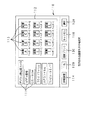
次に、本例のプリンタ装置の回路構成を図2に示す。回路上も先に図1に示した構成と略々同様であり、外部接続機器13、画像入力手段7、画像データ入出力部27、画像処理部6、画像表示出力部2、指示デバイス8、画像印画部3に対応する回路を有する。すなわち、画像入力手段7に対応して画像データインターフェース回路39、リムーバブルメディアドライブ装置40、フィルム読み取り装置41、コンピュータインターフェース回路42を有し、画像データ入出力部27に対応して画像データ入出力回路31を有する。
【0234】
また、画像処理部6に対応する回路としてデータ処理回路36を有し、内部にデータ加工部、表示デバイス処理部、映像信号処理部、印画出力処理部を有する。
【0235】
さらに、指示デバイス8として、本例のプリンタ装置上に配されて使用者の入力操作を可能とする複数のキー38aや、表示デバイス15として配される液晶モニタ45a上に形成され、ペン状の先細形状の入力装置で使用者の入力操作を可能とするペンタッチ入力デバイス38bを有し、後述のヒューマンインターフェース部28に対応する回路に入力するための指示デバイスインターフェース回路38cを有する。この指示デバイスインターフェース回路38cは、チャタリング現象等に起因する誤入力を防止し、一定時間、キー38a或いはペンタッチ入力デバイス38bの同一部分が連続して押圧されると、複数回その操作がなされたものとみなし、その回数分だけ後述のヒューマンインターフェース部28に対応する回路に入力を伝達する。
【0236】
さらにまた、画像表示出力部2の表示デバイス15に対応するものとして、ここでは液晶モニタ45aが配され、画像メモリ20中の画像データが転送され、転送された画像データと後述のヒューマンインターフェース部28に対応する回路からの表示制御信号に基づき、液晶モニタ45a上に表示するメニュー画面やペンタッチ入力デバイス用操作表示画面を合成し、液晶モニタ45aに表示可能な駆動信号に変換する表示デバイス出力回路45bも有する。
【0237】
さらに、画像メモリ20から転送された画像データと後述のヒューマンインターフェース部28に対応する回路からの表示制御信号に基づき、外部モニタ上に表示するメニュー画面やペンタッチ入力デバイス用操作表示画面を合成し、外部モニタに表示可能な標準映像信号としての例えばNTSC信号に変換する映像信号出力回路46も有する。この場合、上記液晶モニタ45aと外部モニタに表示される画像は同一であっても異なっていても良い。
【0238】
さらには、画像印画部3に対応してプリントヘッド駆動回路56とプリントヘッド25を有する。そして、上記プリントヘッド25を使用して例えば記録紙といった記録媒体に印画画像を形成する際に必要な機構部の制御をする時に機構部の全体的な制御を行う後述のシステム制御CPU61によるソフトウエアからのメカ制御信号に基づき、各種モーターやクラッチ、ヘッドメンテナンス機構等を駆動すると同時に、記録媒体の動きやプリントヘッドの動きを検出する各種センサーからの入力を受け付け、これを後述のシステム制御CPU61に知らせる等の印画に必要とされる機構部の駆動及び状態検出を行う印画出力機構制御回路47を有する。
【0239】
また、このプリンタ装置においては、システムROM62やフラッシュメモリ63内の制御ソフトウエアによりワーキングRAM64を使用するシステム制御CPU61を有し、これがプリンタ装置全体の制御を行っており、前述のヒューマンインターフェース部28に対応する回路としても機能している。
【0240】
従って、これらはシステム制御バス65により接続されており、このシステム制御バス65には、上述の画像データ入出力回路31、データ処理回路36、指示デバイスインターフェース回路38c、表示デバイス出力回路45b、映像信号出力回路46、印画出力機構制御回路47、画像印画部3も接続されている。なお、これらのうち、画像データ入出力回路31、データ処理回路36、表示デバイス出力回路45b、映像信号出力回路46、画像印画部3は画像メモリ20の画像データバス66にも接続されている。
【0241】
上記フラッシュメモリ63中の制御ソフトウエアは、リムーバブルメディアドライブ装置40又はコンピュータインターフェース回路42から画像データ入出力回路31を経由して入れ替えることが可能となされていても良い。また、データ処理回路36の動作で独自に制御ソフトウエアを必要とし、データ処理回路36内にROM又は不揮発性RAMが存在しないときは、システムROM62或いはフラッシュメモリ63からデータ処理回路36内で必要とされるソフトウエアをデータ処理回路36内に転送するような構成を取ることもできる。この場合、データ処理回路36内で必要とするソフトウエアをリムーバブルメディアドライブ装置40及びコンピュータインターフェース回路42から入力して、一旦、フラッシュメモリ63若しくはワーキングRAM64に蓄え、その後、データ処理回路36に転送できるようにしておくのが好ましい。
【0242】
上記システム制御CPU61がシステムROM62やフラッシュメモリ63内の制御ソフトウエアにより実行する制御には、以下のようなものがある。先ずは、プリンタ装置全体の制御が挙げられる。この他、画像データ入出力回路31を経由して画像データインターフェース回路39、リムーバブルメディアドライブ装置40、フィルム読み取り装置41、コンピュータインターフェース回路42の駆動制御及びそれぞれの制御によって入力された画像データの取り扱いや、データ処理回路36における画像データの画質を向上するための補正制御、液晶モニタ45a並びに外部モニタへの画像表示制御、キー38a、ペンタッチ入力デバイス38bからの操作指示の入力と液晶モニタ45a及び外部モニタへの出力を制御するヒューマンインターフェース制御、プリント駆動回路56、プリントヘッド25、印画出力機構制御回路47の制御をすることによる画像印画部3全体の制御等が挙げられる。
【0243】
このことから、上記システム制御CPU61による機構部制御ソフトウエア及び印画出力機構制御回路47は、ラインヘッド又はシリアルヘッドといったプリントヘッド25の形状と動作方法及び記録媒体の動作方法が変わると、そのソフトウエアの内容及び回路内容が変わる。言い換えれば、プリントヘッド25の機構構造によって制御ソフトウエアと制御回路が決定されることとなる。
【0244】
実際に印画がなされる場合には、以下のような処理がなされる。すなわち、図2中外部接続機器13から所定の順番で入力された複数のデジタル画像データ又は映像信号、デジタルデータは、画像入力手段7に対応する画像データインターフェース回路39、リムーバブルメディアドライブ装置40、フィルム読み取り装置41、コンピュータインターフェース回路42により第1のデジタル画像データに変換され、画像データ入出力部27に対応する画像データ入出力回路31に所定の順番で入力される。
【0245】
次に、この第1のデジタル画像データは、システム制御バス65からの入出力制御信号の制御により画像データバス66を経由してデータ処理回路36に送られる。このとき、システム制御CPU61がタイミング等を制御していることは言うまでもない。
【0246】
そして、データ処理回路36により所定の第1のデジタル画像データの所定の特性が所定の範囲内かどうかが自動或いは手動で判定され、所定の範囲内であると判定されれば、必要に応じて画質を向上させるための補正を自動或いは手動で行い、第2のデジタル画像データとし、必要に応じて画像メモリ20に保存等する。上記補正のための処理は前述のように自動で行っても良いし、手動でキー38aやペンタッチ入力デバイス38bから指示デバイスインターフェース回路38cを介してデータ処理回路36に行わせる方法があるが、このときも、システム制御CPU61がタイミング等を制御していることは言うまでもない。
【0247】
上記第1のデジタル画像データの所定の特性が所定の範囲内では無いと判定された場合には、前述したような各処理を選択して行えば良い。
【0248】
また、データ処理回路36により所定の処理がなされた第2のデジタル画像データは、表示デバイス出力回路45b、映像信号出力回路46、プリントヘッド駆動回路56に送られて、画像表示及び画像印画がなされる。この場合も、システム制御CPU61がタイミング等を制御していることは言うまでもなく、これまで述べた各装置がそれぞれの機能を果たしていることは言うまでもない。
【0249】
次に、上述したデータ処理回路36の具体例について説明する。先ず、第1の例として図3に示すようなものが挙げられる。すなわち、このデータ処理回路は、独自にデータ処理CPU71、データ処理プログラムRAM72、データ処理ワーキングRAM73により主に構成されるデータ処理制御システム74を有し、また同機能を有する複数の演算回路75を有し、これら演算回路75にデータを送り、演算回路75から出力されるデータの送付先を制御するデータルータ回路76も有する。このデータルータ回路76の制御はデータ処理制御システム74が行う。さらに、先に図2に示したシステム制御CPU61からの制御をシステム制御バスインターフェース77が受け付ける。そして、上記データ処理制御システム74とデータルータ回路76、システム制御バスインターフェース77はデータ処理バス79により接続されている。さらには各演算回路75に画像データを入力及び出力させるための制御を行う画像データバスインターフェース78も有する。
【0250】
つまり、システム制御CPU61からの制御をシステム制御バスインターフェース77が受付け、データ処理CPU71に伝達するとともに、データ処理CPU71から動作状態等の情報をシステム制御CPU61に送る。
【0251】
このようなデータ処理回路では次のような手順でデータ処理が実行される。なお、ここでは、画像メモリ20中の保持されている画像データに対し、データ処理を実行し、再度画像メモリ20中に保持する動作について説明する。
【0252】
先ずシステム制御CPU61のフラッシュメモリ63或いはシステムROM62からシステム制御バスインターフェース77を経由して、実行するデータ処理ソフトウエアをデータ処理プログラムRAM72に転送する。次に、システム制御CPU61はシステム制御バスインターフェース77を経由してデータ処理の実行開始をデータ処理CPU71に指示する。データ処理CPU71は転送されたデータ処理ソフトウエアに基づいて、画像メモリ20中の処理する画像データを画像データバスインターフェース78を経由して読み出し、さらにデータルータ回路76により処理を行う複数の演算回路75のうちの特定の演算回路に入力する。各演算回路75は、データ処理ソフトウエアに基づいて、入力した画像データに対し、データ処理を実行し、実行した後の画像データをデータルータ回路76及び画像データバスインターフェース78を経由して画像メモリ20中に画像データとして書き込む。
【0253】
続けて次の演算を行う場合には、データルータ回路76を経由して、次の特定の演算回路75に入力する。このように画像メモリ20中の画像データを順次読み出して演算処理を実行し、再度画像メモリ20中に画像データとして書き込むことで、データ処理ソフトウエアに従ったデータ処理を実行する。
【0254】
画像データの処理の途中或いは全ての画像データの処理終了後に、データ処理CPU71は、システム制御バスインターフェース77を経由して、システム制御CPU61へ処理状態又は結果状態を知らせることで、システム制御CPU61は実行しているデータ処理の過程及び結果を知ることが可能となる。上記データ処理ワーキングRAM73は、システム制御CPU61から送られたデータ処理のパラメータやデータ処理CPU71の動作中の状態保持等に使用される。
【0255】
上記複数の演算回路75は同じ処理を実行するように設定されており、画像中のデータ位置によってそれぞれの演算回路75が使い分けられるようになっている。すなわち、例えば、画像中の1列目のデータは演算回路75のうち演算回路Aによって処理し、2列目のデータは演算回路75のうち演算回路Bによって処理するといったように使用される。また、列の代わりに行単位としても良い。
【0256】
また、上記複数の演算回路75はそれぞれが異なる処理を実行するように設定されていても良く、特定の演算回路75により処理されたデータをデータルータ回路76により別の処理を行う別の演算回路75に入力するようにしても良い。このようにすると、実行する処理が複数段ある場合に、画像メモリ20から読み込んだ画像データに対し、必要とされる処理を順次施した後に画像メモリ20に書き込むことが可能となり、画像メモリ20へのアクセス回数を減らすことが可能となり、好ましい。
【0257】
これら複数の演算回路75の使用方法は、予め固定しても良く、或いはデータ処理プログラムによる設定によって可変できるようにしても良い。並列接続された演算回路75の個数は要求される処理速度、それぞれの演算回路を構成する回路規模等によって選択決定される。
【0258】
データ処理回路としては、図4に示すようなものも挙げられる。図4に示すデータ処理回路は、先に図3に示したデータ処理回路から演算回路75とデータルータ回路76を除いた以外は同様の構成を有するものであるので、同一の符号を付し、説明を省略する。ただし、データ処理CPU71として高速処理が可能なものが用いられ、DSPやRISC CPUや専用データ処理CPUが用いられる。
【0259】
上記データ処理回路としては、図5に示すようなものも挙げられる。すなわち、複数個のデータ処理回路80が並列に並び、各データ処理回路80がシステム制御バスインターフェース77を経由してシステム制御CPU61による装置全体の制御システムに接続され、更に画像データバスインターフェース78を経由して画像データバス66に接続されるものである。各データ処理回路80は専用演算回路で構成する、或いは汎用演算回路と汎用演算制御回路とから構成する、汎用演算制御回路のみで構成されても良い。システム制御CPU61による制御ソフトウエアが、システム制御バスインターフェース77を経由し、各データ処理回路80に画像メモリ20中の画像データに対してデータ処理を実行するように制御を行う。各データ処理回路80は先に図3に示した演算回路75のようにデータの配列に応じて、同じ処理をさせるようにしても、異なった処理をさせるようにしても良い。
【0260】
次に、本例のプリンタ装置におけるデータ処理の流れについて図6及び図7を用いて説明する。なお、図6及び図7中データの流れを示す線に付随する斜線は8bit以上/色のデータであることを示す。先に図1及び図2を用いても説明したように、図6に示す画像入力手段7のうち、コンピュータインターフェース回路42においては外部から入力されたRGB画像データを画像データ入出力回路31に対してRGB画像データとして出力し、画像入力手段7のうち、画像データインターフェース回路39、リムーバブルメディアドライブ装置40及びフィルム読み取り装置41においては、読み取った画像データ又は映像信号を画像データ入出力回路31に対してRGB画像データとして出力する。
【0261】
次に、上記画像データ入出力回路31において、各画像入力手段7から入力された画像データを同列に扱えるように処理し、データ加工部5に出力する。
【0262】
上記データ加工部5は、図7に示すように、圧縮伸長部81、拡大縮小部82、階調修正部83、色調修正部84、輪郭強調修正部85、他修正部86、画像合成編集部87、画像加工部88により構成されるものであり、画像データ入出力回路31から入力された画像データの所定の情報及び所定の特性が所定の範囲内であるかどうかを判定し、必要に応じて表示デバイス45aや外部モニタでの表示画像、画像印画部3により印画される印画画像の画質を向上するために、画像データを補正したり、画像データに特徴的な特性がある場合には、補正及び画質を向上させるための処理を行う部分である。
【0263】
上記圧縮伸長部81は、画像メモリ20中に画像データを可逆若しくは不可逆圧縮された形態で保持する場合に必要とされる。データ加工部5に入力したRGB画像データ及び各処理を施した後のRGB画像データ並びに必要に応じて各処理間のRGB画像データを圧縮して画像メモリ20中に圧縮された画像データとして保持する。また、画像メモリ20中で圧縮されて保持されている画像データを読み出して伸長し、圧縮されていないRGB画像データとして色々な処理を実行し、データ加工部5内の各部に出力する機能も有する。
【0264】
RGB画像データは、データ加工部5に入力されると、拡大縮小部82に入力される。上記拡大縮小部82は、画像データの所定の特性を画像サイズ特性として、所定の範囲内かどうかの判定と必要に応じた補正を行い、実質的に画像補正部として機能する部分である。すなわち、入力された画像データが本例のプリンタ装置のデータ加工部5により取り扱うことが可能なサイズ範囲外の場合に、画像データに対して拡大或いは縮小処理を行う部分である。
【0265】
RGB画像データは、上記拡大縮小部82の次に階調修正部83に入力される。上記階調修正部83は、画像データの所定の特性を階調特性ヒストグラムとして、所定の範囲内かどうかの判定と必要に応じた補正を行い、実質的に画像補正部として機能する部分である。すなわち、入力された階調特性ヒストグラムが所定の範囲内とされているものの、例えば画像データの階調特性ヒストグラムが著しく偏っている場合等の時、印画出力した場合に画像の画質が向上するように入力画像データの階調特性を修正する。特に、被写体の撮影時に露光量が適正でない場合、画像全体が暗くなり過ぎたり、明るくなりすぎたりするため、これを修正して画像全体の階調特性を改良する部分である。また、入力画像データのガンマ特性に関しても同様に改善することが可能な場合には、ガンマ特性の修正を実行する。
【0266】
また、上記階調修正部83においては、階調特性ヒストグラムが所定の範囲内でないと判定しても、前述したように使用者からの指示があれば、補正できる範囲のみの補正や外部からの入力に応じた補正も行うことが可能である。
【0267】
RGB画像データは、上記階調修正部83の次に色調修正部84に入力される。上記色調修正部84は、上述の階調修正部83と同様に、画像データの所定の特性を色調特性として、所定の範囲内かどうかの判定と必要に応じた補正を行い、実質的に画像補正部として機能する部分である。すなわち、入力された画像データの色調特性が所定の範囲内とされているものの、例えば入力された画像データの色調特性が著しく偏っている場合等の時、印画出力した場合に画像の画質が向上するように入力画像データの色調特性を修正する。全般的な色調修正の他、特定の色調、特に肌色や灰色の色調が適正な範囲から外れている場合に、その部分が適正範囲となるように修正することも可能である。
【0268】
また、上記色調修正部84においては、色調特性が所定の範囲内でないと判定しても、前述したように使用者からの指示があれば、補正できる範囲のみの補正や外部からの入力に応じた補正も行うことが可能である。
【0269】
RGB画像データは、上記色調修正部84の次に輪郭強調修正部85に入力される。上記輪郭強調修正部85は、上述の階調修正部83と同様に、画像データの所定の特性を輪郭特性として、所定の範囲内かどうかの判定と必要に応じた補正を行い、実質的に画像補正部として機能する部分である。すなわち、入力された画像データの輪郭特性が所定の範囲内とされているものの、例えば入力された画像データの画像の輪郭がはっきりしていない、或いは強調されすぎている場合、輪郭強調の修正処理を行い、画像の輪郭を適正に修正する。
【0270】
また、上記輪郭強調修正部85においては、輪郭特性が所定の範囲内でないと判定されても、前述したように使用者からの指示があれば、補正できる範囲のみの補正や外部からの入力に応じた補正も行うことが可能である。
【0271】
RGB画像データは、上記輪郭強調修正部85の次に他修正部86に入力される。上記他修正部86は、所定の特性が所定の範囲内となされているものの、前述したような種々の理由により所定の範囲内では無いかどうかを判定し、必要に応じて補正をする。
【0272】
すなわち、所定の範囲内では無い表示がなされた後、前述したように使用者からの指示があれば、補正できる範囲のみの補正や外部からの入力に応じた補正を行う。
【0273】
上述した例においては、入力された画像データが各処理部において順次補正処理される例について述べたが、これらの処理の中で不要な処理は省くようにしても良く、また処理の順番も変更可能であることは言うまでもない。
【0274】
上記のようにして各補正処理を受けたRGB画像データは、次に画像合成編集部87及び画像加工部88に入力される。これらは、ヒューマンインターフェース部からの使用者の指示に基づいて、入力画面に対して種々の加工処理を行い、また複数の入力画像に対しそれらを合成編集して、最終的に印画するための画像を生成する部分である。
【0275】
また、これらの部分においては、入力画像データに予め用意された画像パターンを合成することも可能である。さらには、編集作業中のヒューマンインターフェース部の制御によって、使用者が所望する画像パターンをペンタッチ入力デバイス等の指示デバイスから入力し、この画像パターンと入力された画像パターンを合成することも可能である。
【0276】
このような画像データの合成・編集・加工を実行する制御ソフトウエア及び予め用意される画像パターンは、リムーバブルメディアドライブ装置及びコンピュータインターフェース回路等から新たに入力できるような構成を取ることが可能である。
【0277】
データ加工部5から出力されたRGB信号は、表示デバイス処理部22及び映像信号処理部23、印画出力処理部24にそれぞれ入力される。
【0278】
上記表示デバイス処理部22は、表示デバイス45aが特徴的な表示出力特性を有しており、データ加工部5から出力された画像データをそのまま表示デバイス45aにより表示しても表示デバイス45aによる表示出力特性のため、高画質表示及び印画した場合と同等の画質表示とならない場合に、表示デバイス45aに特徴的な表示出力特性を補正するような処理を実行する部分である。この表示デバイス処理部22は、後述するプリント適合補正部91、出力特性補正部92、出力ガンマ変換部93が順次配されて構成される。
【0279】
上記映像信号処理部23は、データ加工部5から出力された画像データをNTSC信号に代表される標準的な映像信号に変換して出力するための処理を実行する部分である。この映像信号処理部23は、後述するプリント適合補正部94、出力特性変換部95、出力ガンマ変換部96が順次配されて構成される。また、上記映像信号処理部23においては、画像データの表現可能特性範囲が標準的な映像信号で規定される表現範囲と異なる場合、画像データの表現範囲を標準的な映像信号の表現範囲に変換する処理も含む。なお、上記映像信号処理部23においては、標準的な映像信号の代わりに標準的な映像信号に準じた映像信号とすることも可能である。特に標準的な映像信号より彩度を拡げる(鮮やかにする)ことは、画像をより綺麗に表示させるために行われる。
【0280】
そして、上記印画出力処理部24は、データ加工部5から出力された画像データをプリントヘッド25から記録媒体上に記録するため、画像データからプリントヘッド駆動回路56に入力可能な信号(印画データ)に変換する部分である。この印画出力処理部24における処理は、LUT(ルックアップテーブル)による変換処理、或いは積和演算等が高速に実行できる演算回路を利用した演算処理、或いは高速演算処理アルゴリズムを持つソフトウエアによって実現する演算処理、或いは専用変換回路による処理等で実現される。演算処理を順次実行する場合、常時入力画像データにおける各データのビット数と同一のビット数で取り扱うと、各データの有効精度が悪化する場合が多い。この場合は、最初の画像データのビット数に対して、演算途中での各データのビット数を増加させ、最後の処理で増加したビット数を減少させることで、有効精度の悪化を避けることが可能である。
【0281】
上記印画出力処理部24は、RGB−CMY変換部98、色補正部99、黒抽出下色除去部100、出力ガンマ補正及び階調修正部101、シャープネス修正部102、出力特性変換部103が順次配されて構成される。
【0282】
上記RGB−CMY変換部98は、RGB画像データをプリントヘッド25で使用するC(Cyan),M(Magenta),Y(Yellow)の各インク又はトナーの各色のデータに変換処理する部分である。濃度Log変換或いは補色変換、或いは線形マスキング変換等によって実現される。
【0283】
上記のようにして、CMY画像データに変換された画像データは、色補正部99に入力される。上記色補正部99は、CMY画像データに変換された後、CMYの各インク又はトナーの分光吸収特性が減法混色による理想的な特性と異なっていることから生じる画像印画部3による印画画像の色調(特に色相と彩度)のずれを補正する部分である。
【0284】
上記色補正部99は、LUT(ルックアップテーブル)と演算による変換、又は線形マスキング演算、非線形マスキング演算等により実現される。また、画像データの表現可能最大特性範囲とプリントヘッド25による記録媒体上の印画画像の表現可能最大範囲が異なってくる場合も多いため、画像データによる最大範囲が印画による最大範囲よりも広い場合には、そのままでは画像データの表現範囲のうち、印画の表現範囲を越えた部分の再現が出来なくなる。このため、上記色補正部99においては、この越えた部分を印画上で表現するために、画像データ全体を圧縮変換したり、或いはクリップ変換したりする必要が生じてくる。さらには、この圧縮変換、クリップ変換に伴って色調のズレが生じないような変換方法をとることもある。
【0285】
次に、CMY画像データは黒抽出下色除去部100に入力される。この黒抽出下色除去部100は、プリントヘッド25に黒色(以下、BKと称する。)のインク或いはトナーがある場合に、CMYの各データにおいて、それらがBKの成分を有する場合に、そのBK成分の部分をBKインク或いはBKトナーに置き換えるための処理を行う。その後、BKに置き換えられたCMY画像データ中の各BK成分をCMY画像データのデータ値から取り除く。
【0286】
このCMY中のBK成分のBKインクまたはトナーへの置換には色々な手法があり、全部置換する方法、所定の割合のみを置換する方法、所定の濃度以上の領域で置換する方法等様々な方法が挙げられる。このようにCMYのデータのうち、BK成分をBKインクまたはトナーにより表現することにより、CMYのそれぞれのインク又はトナーでは再現することが不充分な画像中の黒表現を充分なレベルで実現することができる。なお、BK成分のデータは図6中Kとして示すこととする。
【0287】
続いて、上記CMYK画像データは、出力ガンマ補正及び階調修正部101に入力される。上記出力ガンマ補正及び階調修正部101は、プリントヘッド25による記録媒体上への画像再現特性において、その記録インク又はトナー及び中間調再現方法により特徴的な印画出力特性を持つ場合、その印画出力特性に適した出力ガンマ補正及び階調修正を行う部分である。この出力ガンマ補正及び階調修正部101においては、元となる画像データに対し、印画した場合の階調再現が最も良くなるような変換が行われる。
【0288】
次に、上記CMYK画像データは、シャープネス修正部102に入力される。このシャープネス修正部102は、輪郭強調及びスムージング処理を行って印画画像の画質を向上する部分である。
【0289】
さらに、上記CMYK画像データは、出力特性変換部103に入力される。この出力特性変換部103は、プリントヘッド25の種類及びプリントヘッド25の駆動方法、記録媒体の種類、インク又はトナーの種類等による特徴的な補正を実行して印画画質を向上させる部分である。具体的には、印画時の環境温度補正、熱履歴補正、プリントヘッド25の各素子のばらつき補正等が挙げられる。これらの補正処理の中、プリントヘッド駆動回路56で補正するのが適しているものについては、プリントヘッド駆動回路56において補正を行えば良い。
【0290】
そして、本例のプリンタ装置においては、表示デバイス45aによる表示画像及び外部モニタによる表示画像の画質を画像印画部3による印画画像の画質と視覚的に同等とするべく、上記画像印画部3における印画画質を規定する印画特性設定に対応して、上記画像表示出力部2における表示画質を規定する表示出力特性設定を補正するようにしている。
【0291】
具体的には、印画出力処理部24の印画特性の変更、具体的には処理内容等に対応して、画質を視覚的に同等とするために表示デバイス処理部22と映像信号処理部23が行うべき補正の内容を示す補正パラメータを表示デバイス処理部22のプリント適合補正部91と映像信号処理部23のプリント適合補正部94に入力するようにしている。
【0292】
すなわち、上記表示デバイス処理部22においては、RGB画像データは最初に入力されるプリント適合補正部91において補正パラメータを有した状態となり、この状態で処理が進められ、表示デバイス45aに表示される。
【0293】
一方の映像信号処理部23においても同様であり、RGB画像データは最初に入力されるプリント適合補正部94において補正パラメータを有した状態となり、この状態で処理が進められ、外部モニタに表示される。
【0294】
この結果、表示デバイス45aによる表示画像及び外部モニタによる表示画像の画質と画像印画部3による印画画像の画質が視覚的に同等となる。
【0295】
上述の例においては、表示デバイス処理部22及び映像信号処理部23の表示出力特性を画像印画部3の印画特性、具体的には印画出力処理部24による処理内容に合わせて補正して、画像表示出力部による表示画像と画像印画部の印画画像の画質を視覚的に同等とするようにしている。しかしながら、画像印画部3の印画特性、具体的には印画出力処理部24による処理内容を表示デバイス処理部22及び映像信号処理部23の表示出力特性に合わせることも可能である。
【0296】
すなわち、データ処理の流れを図8に示すようにすることも可能である。図8は、表示デバイス処理部22のプリント適合補正部91と映像信号処理部23のプリント適合補正部94が無いことと、これに伴って印画出力処理部24からの補正パラメータを示す線が無いことのみ、図6と異なるため、他の箇所については同一の符号を付し、説明を省略することとする。
【0297】
ただし、データ処理の流れを図8に示すような方法とした場合、例えば表示デバイス処理部22の表示出力特性の変更等に対応して、画質を視覚的に同等とするために印画出力処理部24が行うべき補正の内容を示す補正パラメータを印画出力処理部24の色補正部99と出力ガンマ補正及び階調修正部101に入力するようにしている。
【0298】
すなわち、上記印画出力処理部24においては、RGB画像データは実質的に画像の特性を決定する色補正部99と出力ガンマ補正及び階調修正部101において補正パラメータを有した状態となり、この状態で処理が進められ、画像印画部3により印画される。
【0299】
この結果、表示デバイス45aによる表示画像の画質と画像印画部3による印画画像の画質が視覚的に同等となる。
【0300】
なお、上記のような表示デバイス処理部22及び映像信号処理部23、印画出力処理部24に不揮発メモリを備え、補正パラメータを書き換え可能な状態で保存するようにすれば、常に最適な補正パラメータを使用して処理を行うことができ、好ましい。
【0301】
先に、表示デバイス15或いは外部モニタにメニュー画面等を表示することについて述べたが、その具体的な表示例を操作手順に沿って述べる。これらの画像のうち、最初の画面としては、例えば図9に示すようなメニューを示す画面110が挙げられる。なお、ここでは、画面の所定の部分に直接接触することにより入力処理がなされる画面を想定している。この画面110は、図9中に示すように、外部接続機器及び画像入力手段を選択するための各名称が表示されている複数の入力部選択キー111が表示されるとともに、画像表示領域112が主に表示されてなる。上記画像表示領域112は、入力部選択キー111により外部接続機器及び画像入力手段を選択した場合に、選択した手段においてアクセス可能な画像113が領域内に縮小画像として表示されるものである。
【0302】
また、この画面110には、画像113を特定の条件で選択する等の場合に使用する詳細設定キー114や縮小画像として表示されている画像113を選択する選択キー128、印画枚数を入力する印画枚数入力キー129、自動的に判定及し補正して印画を行う自動印画方式を開始する自動プリントキー130、処理を中止するためのキャンセルキー116も表示される。
【0303】
先ず、使用者が、上記表示画面において、入力部選択キー111により外部接続機器及び画像入力手段のうちの1つを選択指定すると、これにより読み込むことが可能となる複数の画像113が画像表示領域112に表示される。このとき、上記画像113の情報に付随する情報、例えばヘッダー情報等がある場合には、各画像113に関連してその情報を表示するようにしている。
【0304】
次に、使用者が、表示されている複数の画像113から、選択キー128により所望の画像113を選択すると、この選択された画像113は選択されたことを示すような表示がなされる。
【0305】
このように選択された画像113を全て同じ枚数で印画する場合には、印画枚数入力キー129により印画枚数を設定する。
【0306】
表示された複数の画像113中に印画したい画像が無い場合には、選択を行わなければ良い。
【0307】
また、上記詳細設定キー114を選択すると、条件の入力等が行えるようにしておき、使用者が撮影日時順等の特定条件で画像113の選択を行ったりすることが可能なようにすれば良い。
【0308】
上記のようにして印画する画像データの選択が行われ、特定条件が設定され、これらを自動的に判定し補正して印画を行う場合には、自動印画方式を開始する自動プリントキー130を選択する。
【0309】
すると、予め選択された複数の画像データに対し、判定、補正、印画の一連の処理が順次なされて、予め設定された枚数で印画がなされる。
【0310】
上記のように複数の画像データを表示する際、既に印画がなされた画像データに関しては、縮小画像として表示される画像データの表示を異なるものとし、印画済であることを明示することが好ましい。
【0311】
また、各画像データのうち、補正処理中のものについては、補正処理中であることを明示することも好ましい。さらには、補正処理した結果の画像データを拡大して示すことも好ましい。
【0312】
自動プリントキー130が選択された場合、画面として図10(a)に示すように、画面110に選択された複数の画像データのうちの1つの画像117と、画質を改善するために順次実行される処理A,処理B,処理C・・・処理Xの各補正処理を示す複数の処理表示キー118、印画開始を指示するプリントキー119、処理を中止するためのキャンセルキー120を表示させる。
【0313】
すなわち、この画面においては各補正処理の進行状況が表示され、実行中或いは実行終了時に処理結果画像が表示される。
【0314】
補正処理を画像117の中の特定の部分から開始できる場合には、処理が終了した範囲の表示を処理後の表示へと徐々に変化させていくようにすれば、処理が画像117中のどの範囲まで実行されたかが確認され、好ましい。
【0315】
上記補正処理としては、可変パラメータを有する処理と、このような可変部分を有しない処理が想定される。
【0316】
そこで、例えば処理Aが可変パラメータを有する処理と仮定する。このような補正処理が実施されている場合には、例えば図10(b)に示すように、画像117と、現在行われている処理を示す処理表示部121、前の画面(図10(a)に示した画面)に戻ることが表示されてこれを選択する選択キー122、処理を中止するキャンセルキー123を有し、可変パラメータ選択部分126、処理を確定する決定キー127を有する画面110を表示すれば良い。なお、この画像において画像に付随する所定の情報或いは画像の所定の特性が所定の範囲内では無いと判定された場合には、自動的な補正が不可能であることを示す自動補正範囲外表示131も表示すれば良い。
【0317】
上記可変パラメータ選択部分126は、図10(b)中に示すように、可変パラメータのレベルを表示するスライドボリューム表示部125と可変パラメータを上下させる調整キー124a,124bを有する。ここでは、図10(b)中向かって左側の調整キー124aを押すと可変パラメータのレベルが左側に移行し、図10(b)中向かって右側の調整キー124bを押すと可変パラメータのレベルが右側に移行する。例えば、可変パラメータを画像の輝度とし、図10(b)中向かって左側の調整キー124aが輝度を下げるキーとし、図10(a)中向かって右側の調整キー124bが輝度を上げるキーとすると、これら調整キー124a,124bを調整してスライドボリューム表示部125のレベルを変化させることにより、画像の輝度も変化して表示される。
【0318】
従って、上記のように自動補正が不可能であることを示す自動補正範囲外表示131が表示された場合には、前述のように処理を中止する、或いは自動的な補正が可能な範囲で補正処理を行う、又は上記のような手法で手動にて可変パラメータを変更し補正パラメータを決定する処理を行えば良い。
【0319】
一方、例えば処理Bが可変パラメータを有しない処理と仮定する。このような補正処理が実施されている場合には、例えば図10(c)に示すように、画像117と、現在行われている処理を示す処理表示部121、前の画面(図10(a)に示した画面)に戻ることが表示されてこれを選択する選択キー122、処理を中止するキャンセルキー123を有し、処理を確定する決定キー126を有する画面110を表示すれば良い。なお、この画像において画像に付随する所定の情報或いは画像の所定の特性が所定の範囲内では無いと判定された場合には、自動的な補正が不可能であることを示す自動補正範囲外表示132も表示すれば良い。
【0320】
従って、上記のように自動補正が不可能であることを示す自動補正範囲外表示132が表示された場合には、前述のように処理を中止する、或いは自動的な補正が可能な範囲で補正処理を行えば良い。
【0321】
上記図10(b)及び図10(c)に示すような画面上で各補正処理を行い、使用者がこの処理を終了しても良いと確認した場合には、決定キー127を選択する。すると、再度図10(a)に示したような画面に戻り、印画が開始される。
【0322】
上記のような補正処理を行う場合、輝度の補正を行うことが好ましい。すなわち、例えば図11に示すような画像を印画しようとするとき、その輝度ヒストグラムが図12に示すように平均的に分布している場合には、充分な画質の印画を形成することが可能である。なお、図12においては、横軸に画素の輝度レベルを示し、縦軸に画素量を示す。
【0323】
しかしながら、図13に示すように輝度の分布が全体的に高輝度(ハイライト)側に分布している場合、或いは図14に示すように輝度の分布が全体的に低輝度(シャドー)側に分布している場合には、このまま印画すると充分な画質を得ることができない。なお、図13及び図14においても、横軸に画素の輝度レベルを示し、縦軸に画素量を示す。
【0324】
そこで、例えば図13に示すような場合には、画像データのある部分を拡大し、図12に示すような輝度が平均的に分布している画像に補正することが好ましい。ただし、図12よりも更に極端に明るい部分に偏っていると補正を行っても充分な画質を得ることはできない。このような場合には、自動的な補正処理を中止し、使用者に対応を促すような表示を行うことが好ましい。この場合、自動的な補正処理を実行するか中止するかを予め決めておくことが好ましい。また、この場合、画像データの種類と補正処理内容により設定の種類と範囲が異なるため、予め最適な範囲を設定しておく必要がある。
【0325】
図14に示した輝度の分布が全体的に低輝度(シャドー)側に分布している場合においても同様であり、画像データのある部分を拡大し、図12に示すような輝度が平均的に分布している画像に補正することが好ましい。ただし、図12よりも更に極端に暗い部分に偏っていると補正を行っても充分な画質を得ることはできない。このような場合には、自動的な補正処理を中止し、使用者に対応を促すような表示を行うことが好ましい。この場合、自動的な補正処理を実行するか中止するかを予め決めておくことが好ましい。また、この場合、画像データの種類と補正処理内容により設定の種類と範囲が異なるため、予め最適な範囲を設定しておく必要がある。
【0326】
次に、本例のプリンタ装置における概略動作を図15〜図21に示すフローチャートを用いて説明する。
【0327】
先ず図15中に示すように、ステップS1において、電源がONになると、これによりステップS2において表示デバイス及び/又は外部モニタ上の初期画面として先に図9に示したような処理メニューが表示される。続いてステップS3において画像データを入力する画像入力手段或いは外部接続機器の選択指示が行われるかを判定し、その指示が行われると、指示された所望のものを選択し、例えばステップS4において画像データインターフェース部を駆動する。上記画像データを入力する画像入力手段或いは外部接続機器は前述のように複数種あるので、これに応じて、ステップS5においてはリムーバブルメディアドライブ部駆動がなされ、ステップS6においてはフィルム読み取り部駆動がなされ、ステップS7においてはコンピュータインターフェース部駆動がなされる。すなわち、ステップS3の選択に応じて、ステップS4〜S7のうちの何れかに進む。
【0328】
一方、ステップS3において画像データを入力する画像入力手段或いは外部接続機器の選択指示が行われていない場合には、再度ステップS3において画像データを入力する画像入力手段或いは外部接続機器の選択指示が行われるかどうかを判定する。すなわち、ステップS3にて繰り返し画像入力手段或いは外部接続機器の選択指示の判定を行い、その選択指示がなされるのを待つ。
【0329】
上述のように、ステップS4〜S7のうちの選択された画像入力手段或いは外部接続機器から入力された画像データは、ステップS8において表示デバイス或いは外部モニタ上に画像として表示される。このとき、選択された画像入力手段或いは外部接続機器から複数の画像データが出力される場合、出力された複数の画像データは表示デバイス或いは外部モニタ上に複数の縮小画像として表示される。このとき、各画像データは第1のデジタル画像データとなされている。
【0330】
次にステップS9において、画像データを入力する画像入力手段或いは外部接続機器の選択の変更を行う指示がなされるかどうかが判定される。画像データを入力する画像入力手段或いは外部接続機器の選択の変更の指示が行われない場合には、次にステップS10において表示されている複数の縮小画像の中から処理する画像の選択指示が行われるかを判定する。ここで言う処理は、画像処理部による編集加工補正等の処理及び画像印画部による印画処理及びそのために実行する各処理を示す。
【0331】
一方、上記表示された複数の画像の中から処理を行う画像を選択せずに、再度画像データを入力する画像入力手段或いは外部接続機器の変更指示がなされた場合には、ステップS9において再度画像データを入力する画像入力手段或いは外部接続機器の選択を行い、その選択指示に応じて、ステップS4〜S7のうちの何れかに進む。
【0332】
上記のようにステップS10で選択された画像には、ステップS11において当該画像データを選択したことが分かるような画像選択処理、例えば、選択画像リストに、画像を選択するたびにその画像を示すID情報を追加するといった処理を行い、ステップS12においてこの選択画像データの情報を前述のワーキングRAM内或いは各画像入力手段に保持する。続いてステップS13において、その画像が選択されたことが分かるように表示デバイス及び/又は外部モニタ上の選択された表示画像の表示状態を変更する。
【0333】
そして次に、図16に示すように、ステップS14において、選択された複数の画像データのデータ加工部への入力順を決定する画像データ入力優先順位の設定指示がなされるかどうかの判定が行われる。画像データ入力優先順位の設定指示がなされる場合には、ステップS15において複数の画像データの入力優先順位を設定する処理、すなわち、例えば入力優先方法の選択及び処理順画像リストの作成といった処理を行い、ステップS16においてこの画像データの入力優先順位の情報を上記ワーキングRAM内或いは各画像入力手段に保持する。
【0334】
続いて、ステップS17において画像データの印画枚数の設定指示が行われるかどうかの判定が行われる。画像データの印画枚数の設定指示が行われる場合には、ステップS18において複数の画像データの印画枚数を設定する処理、すなわち、全ての画像データに共通な印画枚数を設定する、或いはそれぞれの画像データ毎に印画枚数を設定する処理を行い、ステップS19においてこの画像データの印画枚数の情報を上記ワーキングRAM或いは画像入力手段に保持する。
【0335】
なお、ステップS14において複数の画像データの入力優先順位の設定指示がなされていないと判定した場合には、そのままステップS17に進む。
【0336】
次に、ステップS20に進んで自動印画方式の起動指示がなされるかどうかの判定を行う。
【0337】
上記ステップS17において印画枚数を設定指示がなされていないと判定した場合、そのままステップS20に進む。
【0338】
さらに、ステップS20において自動印画方式の起動指示がなされた場合には、図17に示すように、ステップS21において選択した画像データの情報及び入力優先順位の情報を前述のワーキングRAM或いは各画像入力手段からデータ加工部に入力する。
【0339】
続いて、ステップS22において入力したこれらの情報に基づいて上記画像データの中から最初に処理する画像データを決定する。次いで、ステップS23において、この画像データの印画枚数情報を前述のワーキングRAM或いは各画像入力手段からデータ加工部に入力する。
【0340】
さらに、ステップS24において上記画像データを完全な状態でデータ加工部に入力し、ステップS25において表示デバイス及び/又は外部モニタ上に表示する。このとき、前述の画像メモリ中に対象となる画像データが完全な状態である場合には、その画像データをデータ加工部へ入力する。また、画像メモリ中に完全な状態の画像データが無い場合には、再度当該画像入力手段或いは外部接続機器から対象画像データをデータ加工部に入力する。
【0341】
そして、ステップS26において、上記画像データに対して補正処理の1種である処理Aが自動的に行われ、ステップS27において処理Aが正常に終了したかどうかが判定される。すなわち、上記画像データの処理Aに関連する所定の情報或いは所定の特性が所定の範囲内であると判定され、処理Aが必要に応じて正常に行われたかどうかが判定される。上記処理Aが正常に終了した場合には、次にステップS28において上記画像データに対して補正処理の1種である処理Bが自動的に行われ、ステップS29において処理Bが正常に終了したかどうかが判定される。すなわち、上記画像データの処理Bに関連する所定の情報或いは所定の特性が所定の範囲内であると判定され、処理Bが必要に応じて正常に行われたかどうかが判定される。上記処理Bが正常に終了した場合には、さらに各補正処理に応じて所定の範囲内かどうかの判定と必要に応じた補正処理が順次行われる。
【0342】
このように補正処理が繰り返され、図18に示すように、ステップS30において、上記画像データに対して最後の補正処理である処理Xが自動的に行われ、ステップS31において処理Xが正常に終了したかどうかが判定される。すなわち、上記画像データの処理Xに関連する所定の情報或いは所定の特性が所定の範囲内であると判定され、処理Xが必要に応じて正常に行われたかどうかが判定される。上記処理Xが正常に終了した場合には、第2のデジタル画像データとされ、ステップS32において印画出力処理部により印画出力処理が実行されて上記第2のデジタル画像データは印画データに変換される。
【0343】
以上、説明した処理A,B・・・X等の処理の実行及びその結果判定の順序は一例であり、選択した画像データの種類や特性及び画像入力手段や外部接続機器の特徴、或いは工場出荷時の設定や使用状況・動作環境によって、実行する処理の種類及びその順序が適宜変更されるようにしても良い。
【0344】
そして、ステップS33において、上記印画データに基づいて印画が行われ、ステップS34において印画枚数が印画枚数情報の所定の印画枚数に達したかどうかが判定される。ここで所定の印画枚数に達していない場合には、再度ステップS33において印画を行う。印画枚数が所定の枚数に達すると、ステップS35において、上記のような処理を行う次に処理するべき選択画像データが有るかどうかが判定される。ここで次の画像データがある場合には、図17に示すようにステップS22に戻って、これ以降の処理を繰り返す。一方、次の選択画像データが無い場合には、図15に示すようにステップS9に戻ってこれ以降の処理を繰り返す。
【0345】
図17に示したステップS27で処理Aが正常に終了しなかったと判定された場合、ステップS271においてこの第1のデジタル画像データの処理を終了し、これを正常終了扱いして次の処理に移るかどうかを判定する。すなわち、この画像データに対する補正処理・印画出力処理・印画動作は中止するが、その次に選択された画像データがある場合にはその画像データに対する各処理を実行する動作に移るかどうかを判定する。これは使用者が指示しても、或いは予め動作モードとして設定しておいても良い。この画像データに対する処理を正常終了扱いで終了する場合には、図18に示すステップS35に進み、次に処理すべき画像データがあるかどうかを判定する。
【0346】
一方、ステップS271においてこの画像データに対する処理を正常終了扱いしない場合には、ステップS272において正常な終了がなされなかったことを意味する異常終了表示が表示デバイス及び/又は外部モニタ上に行われ、図15に示すステップS9に進み、これ以降の処理を繰り返す。
【0347】
ステップS29で処理Bが正常に終了しなかったと判定された場合も同様であり、ステップS291においてこの第1のデジタル画像データの処理を終了し、これを正常終了扱いして次の処理に移るかどうかを判定する。この画像データに対する処理を正常終了扱いで終了する場合には、図18に示すステップS35に進み、次に処理すべき画像データがあるかどうかを判定する。
【0348】
一方、ステップS291においてこの画像データに対する処理を正常終了扱いしない場合には、ステップS292において正常な終了がなされなかったことを意味する異常終了表示が表示デバイス及び/又は外部モニタ上に行われ、これ以降の処理を繰り返す。
【0349】
また、図18に示すステップS31で処理Xが正常に終了しなかったと判定された場合も同様であり、ステップS311においてこの第1のデジタル画像データの処理を終了し、これを正常終了扱いにして次の処理に移るかどうかを判定する。この画像データに対する処理を正常終了扱いで終了する場合には、図18に示すステップS35に進み、次に処理すべき画像データがあるかどうかを判定する。
【0350】
一方、ステップS311においてこの画像データに対する処理を正常終了扱いしない場合には、ステップS312において正常な終了がなされなかったことを意味する異常終了表示が表示デバイス及び/又は外部モニタ上に行われ、これ以降の処理を繰り返す。
【0351】
上記のような自動印画方式における補正処理の手順を処理Xを例にとって説明する。ただし、ここでは処理Xが可変パラメータ値を入力する処理とする。すなわち、図19に示すようにステップS3001において処理Xが自動印画方式において起動される。続いてステップS3002において入力されている第1のデジタル画像データの所定の情報或いは所定の特性が所定の範囲内かどうかの判定を処理を行い、ステップS3003において上記所定の情報或いは所定の特性が所定の範囲内であるかどうかの判定を行う。
【0352】
所定の範囲内であると判定された場合には、ステップS3004において処理Xの可変パラメータの値が自動的に決定され、ステップS3005において画質を改善するための補正処理である処理Xが自動的に実行される。そして、ステップS3006においてこの処理Xが実行された結果の画像を表示する。すると、ステップS3007において処理Xが正常に終了したと判断されて、図18中に示すステップS31に進み、処理Xが正常に終了したと判定される。
【0353】
一方、ステップS3003において上記所定の情報或いは所定の特性が所定の範囲内では無いと判定された場合には、ステップS3008において、その後の対応方法について使用者が手動で入力を行うヒューマンインターフェース(I/F)指示入力モードが設定されているかどうかの判定が行われる。ここで上記ヒューマンインターフェース(I/F)指示入力モードが設定されていると、ステップS3009において先に述べたような第1のデジタル画像データの所定の情報或いは所定の特性が所定の範囲内に無いことを表示デバイス及び/又は外部モニタ上に表示した後、ステップS3010において外部からその後の対応方法についての指示入力が行われるか否かの判定を行う。
【0354】
すなわち、その第1のデジタル画像データに対する補正及び印画処理を中止する、又は可能な範囲で処理Xの可変パラメータの値を自動的に設定し、その値に基づいて画質を改善するための補正処理である処理Xを自動的に実行する、又は手動によりその可変パラメータの値を使用者が入力する、又は全ての自動処理を中止するといった方法のうち、どの方法を用いるかの判定を行う。これらのうち、どの方法を用いるかを予め設定しておいても良い。
【0355】
その後の対応方法についての指示入力が行われると、前述のように当該第1のデジタル画像データについての補正処理を終了させる、或いは可能な範囲での自動補正を行う、或いは手動(マニュアル)で可変パラメータの値の入力を行う、或いは全ての処理を中止させることができる。
【0356】
ここで、処理中の第1のデジタル画像データについての補正処理を終了させる指示入力が行われる、若しくは予めその設定がなされている場合には、ステップS3011で当該第1のデジタル画像データの処理を終了させて、図18中に示すステップS311において当該第1のデジタル画像データの処理が終了したと判定される。
【0357】
または、可能な範囲での自動補正を行う指示入力が行われる、若しくは予めその設定がなされている場合には、ステップS3012で処理Xの可変パラメータの値が可能な範囲内で自動的に決定され、ステップS3005に進み、これ以降の処理が実行される。
【0358】
または、手動(マニュアル)で可変パラメータ値の入力を行う指示入力が行われる、若しくは予めその設定がなされている場合には、ステップS3013でパラメータ値の入力を促す表示がなされ、ステップS3014でパラメータの値が入力されるかどうかの判定がなされ、パラメータの値が入力されると、ステップS3005に進み、これ以降の処理が実行される。パラメータの値が入力されない場合には、再度ステップS3014でパラメータの値が入力されるかどうかの判定が繰り返される。
【0359】
または、全ての処理を中止させる指示入力が行われる、若しくは予めその設定がなされている場合には、ステップS3015において正常な終了がなされなかったことを意味する異常終了したとなされて、図18に示すステップS312に進み、異常終了処理表示がなされて、それ以降の処理がなされる。
【0360】
なお、上記ステップS3010において外部からのその後の対応方法についての指示入力が行われるか否かの判定がなされ、外部からの指示入力が行われず、且つ予めその対応方法の選択についての設定がなされていない場合に、ステップS3016において一定時間が経過したかどうかを判定する。一定時間が経過してしまった場合、すなわち一定時間指示入力が行われなかった場合には、ステップS3011に進み、この第1のデジタル画像データの処理を終了させる。一方、一定時間が経過していない場合には、再度ステップS3010において外部からの指示入力が行われるかどうかの判定が行われる。
【0361】
図16中に示すステップS20において自動印画方式の起動指示がなされていないと判定した場合、次にステップS201において、手動により処理を行うマニュアル印画方式で各画像データに対し、各処理を実行するためのマニュアル処理対象画像の選択指定がなされるかどうかを判定する。ここで、画像の選択指定が行われない場合には、図15中に示すステップS9に戻り、これ以降の処理を実行する。すなわち、ステップS9、ステップS10、ステップS14、ステップS17、ステップS20、ステップS201の各判定が繰り返されて、何らかの入力指示がなされるのを待つ。
【0362】
ステップS201において、手動により処理を行うマニュアル処理対象画像の選択指定がなされた場合には、図20に示すように、ステップS2001において上記画像データを完全な状態でデータ加工部に入力し、ステップS2002において入力された画像データを表示デバイス及び/又は外部モニタ上に表示する。このとき、前述の画像メモリ中に対象となる画像データが完全な状態である場合には、その画像データをデータ加工部へ入力する。また、画像メモリ中に完全な状態の画像データが無い場合には、再度当該画像入力手段或いは外部接続機器から対象画像データをデータ加工部に入力する。なお、ここで画像データは第1のデジタル画像データとなされている。
【0363】
そして、ステップS2003において、印画出力の起動指示が行われるかどうかの判定が行われ、印画出力の起動指示がなされると、ステップS2004において入力された第1のデジタル画像データの印画枚数の設定指示処理を行う。そして、ステップS2005において印画出力処理を行い、ステップS2006において、上記印画データに基づいて印画が行われ、ステップS2007において印画枚数が設定された印画枚数に達したかどうかが判定される。ここで所定の印画枚数に達していない場合には、再度ステップS2006において印画を行う。印画枚数が所定の枚数に達すると、図15中に示すステップS9に戻り、これ以降の処理を繰り返す。
【0364】
また、ステップS2003において印画出力の起動指示がなされていないと判断した場合にはステップS2008において各補正処理中の何れかを選択して実行させる指示入力がなされるかを判定する。処理の選択指示が行われると、自動印画方式のところで述べたように、処理A、処理B・・・処理Xと複数の処理があるので、この中の1種を選択して実行する。
【0365】
例えば処理Aが選択された場合、ステップS2009において手動(マニュアル)により処理Aが実施され、再度ステップS2003において印画出力の起動指示がなされるかどうかの判定が行われ、印画出力の起動指示がなされると、ステップS2004以降の処理がなされ、前述のようにして印画が実施される。
【0366】
一方、他の補正処理も行う場合においては、ステップS2003において印画出力の起動指示がなされずにステップS2008において、他の補正処理、例えば処理Bが選択された場合には、ステップS2010において手動(マニュアル)により処理Bが実施され、再度ステップS2003において印画出力の起動指示がなされるかどうかの判定が行われ、印画出力の起動指示がなされると、ステップS2004以降の処理がなされ、前述のようにして印画が実施される。
【0367】
一方、さらに他の補正処理も行う場合においては、ステップS2003において印画出力の起動指示がなされずに、ステップS2008において、上記のような処理を必要に応じて繰り返し、最後の処理Xが選択されてステップS2011において、手動(マニュアル)により処理Xが実施され、再度ステップS2003において印画出力の起動指示がなされるかどうかの判定が行われ、印画出力の起動指示がなされると、ステップS2004以降の処理がなされ、前述のようにして印画が実施される。
【0368】
このように使用者の所望する処理を順次、或いは所望する順序で対象とする画像データに実行し、その後で使用者の指示で印画処理に移る。
【0369】
上記のような手動(マニュアル)により補正処理を行う手順を処理Xを例にとって説明する。ただし、ここでは処理Xが可変パラメータ値を入力する処理とする。すなわち、図21に示すようにステップS2012において処理Xがマニュアル方式において起動される。続いてステップS2013において入力されている第1のデジタル画像データの所定の情報或いは所定の特性が所定の範囲内かどうかの判定処理を行い、ステップS2014において上記所定の情報或いは所定の特性が所定の範囲内であるかどうかの判定を行う。
【0370】
所定の範囲内であると判定された場合には、ステップS2015において処理Xの可変パラメータの値を選定し、ステップS2016において上記の選定された可変パラメータの値を使用して画質を改善するための補正処理である処理Xを実行する。そして、ステップS2017においてこの処理Xが実行された結果の画像を表示する。
【0371】
上記ステップS2014において上記所定の情報或いは所定の特性が所定の範囲内で無いと判定された場合には、ステップS2018において補正可能な所定の範囲内で可変パラメータの値を選定し、ステップS2016において上記の選定された可変パラメータの値を使用して画質を改善するための補正処理である処理Xを実行する。そして、ステップS2017においてこの処理Xが実行された結果の画像を表示する。
【0372】
続いて、ステップS2019において、処理Xの可変パラメータ値を変更するかどうかを使用者に尋ねるパラメータ入力要求表示を行う。
【0373】
上記ステップS2017において表示された画像で良ければステップS2020における処理Xを終了するかどうかの判定において終了を選択し、ステップS2021において処理Xが終了したと判断する。そして、図20中に示すステップS2003に戻り、これ以降の処理を行えば良い。
【0374】
一方、ステップS2020において、処理Xを終了せず、可変パラメータ値を変更する場合には、ステップS2022においてパラメータ値を入力し、ステップS2030において入力されたパラメータ値で処理Xを行い、ステップS2017において再度結果を表示する。
【0375】
このように、本例のプリンタ装置においては、種々の作業が容易に行われ、取り扱いも容易である。また、画像入力手段の種類に関係なく、同一の操作で作業が行われることから、使用者が作業手順に困惑することもない。
【0376】
【発明の効果】
上述のように、本発明に係るプリンタ装置は、外部より入力されたデジタル画像データ及び/又はアナログ画像信号をアナログ・デジタル変換により第1のデジタル画像データに変換する画像データ入力部と、上記第1のデジタル画像データに対して必要に応じて補正を行い、第2のデジタル画像データとする画像補正部と、上記第1のデジタル画像データ及び/又は第2のデジタル画像データを画像印画部において印画するための印画データに変換する印画出力処理を行う印画出力処理部と、上記印画データに基づいて記録媒体上に印画出力する画像印画部とを有するものである。
【0377】
そして、上記画像データ入力部から画像補正部に少なくとも1種以上の第1のデジタル画像データの入力が行われ、上記画像補正部において、入力された所定の第1のデジタル画像データの所定の特性が所定の範囲内にあるかどうかが判定され、所定の特性が所定の範囲内にある場合には、この所定の第1のデジタル画像データに必要に応じて補正が行われて第2のデジタル画像データとされ、この所定の第1のデジタル画像データ及び/又は第2のデジタル画像データが印画出力処理部において印画データに変換され、上記印画データに基づいて画像印画部において印画出力が行われて印画画像が形成される。
【0378】
すなわち、少なくとも1種以上の第1のデジタル画像データのうち、所定の特性が所定の範囲内にあると判断されたもののみが、必要に応じて補正されて第2のデジタル画像データとされ、印画されることとなり、所望の画像の印画が容易に行われる。
【0379】
また、上記本発明のプリンタ装置においては、上記画像データ入力部から複数種の第1のデジタル画像データが所定の順序で画像補正部に入力され、画像補正部内で所定の第1のデジタル画像データの所定の特性が所定の範囲内にあるかどうかの判定、必要に応じた補正、印画データへの変換、印画出力という処理が、複数種の第1のデジタル画像データに対し入力された順序で順次行われる。
【0380】
すなわち、上記本発明のプリンタ装置においては、複数種の第1のデジタル画像データのうち、所定の特性が所定の範囲内にあると判断されたもののみが、順次、必要に応じて補正されて第2のデジタル画像データとされ、印画されることとなり、所望の画像の印画が容易に行われる。
【0381】
そして、上記本発明のプリンタ装置においては、上記所定の第1のデジタル画像データの所定の特性が所定の範囲内に無いと判定された場合には、補正、印画データへの変換、印画出力という処理が行われないことから、無駄な印画が抑えられ、不要な印画が極力抑えられる。
【図面の簡単な説明】
【図1】本発明に係るプリンタ装置の構成を示す模式図である。
【図2】本発明に係るプリンタ装置の構成を示す回路図である。
【図3】本発明に係るプリンタ装置のデータ処理回路の一例を示す回路図である。
【図4】本発明に係るプリンタ装置のデータ処理回路の他の例を示す回路図である。
【図5】本発明に係るプリンタ装置のデータ処理回路のさらに他の例を示す回路図である。
【図6】本発明に係るプリンタ装置のデータ処理の流れの一例を示す回路図である。
【図7】本発明に係るプリンタ装置のデータ加工部におけるデータ処理の流れを示す回路図である。
【図8】本発明に係るプリンタ装置のデータ処理の流れの他の例を示す回路図である。
【図9】本発明に係るプリンタ装置の表示デバイス或いは外部モニタに表示される画像の一例を示す模式図である。
【図10】本発明に係るプリンタ装置の表示デバイス或いは外部モニタに表示される画像の他の例を示す模式図である。
【図11】本発明に係るプリンタ装置の表示デバイス或いは外部モニタに表示される画像のさらに他の例を示す模式図である。
【図12】画像の輝度ヒストグラムの一例を示す模式図である。
【図13】画像の輝度ヒストグラムの他の例を示す模式図である。
【図14】画像の輝度ヒストグラムのさらに他の例を示す模式図である。
【図15】本発明に係るプリンタ装置における概略動作の一部を示すフローチャートである。
【図16】本発明に係るプリンタ装置における概略動作の一部を示すフローチャートである。
【図17】本発明に係るプリンタ装置における概略動作の一部を示すフローチャートである。
【図18】本発明に係るプリンタ装置における概略動作の一部を示すフローチャートである。
【図19】本発明に係るプリンタ装置における概略動作の一部を示すフローチャートである。
【図20】本発明に係るプリンタ装置における概略動作の一部を示すフローチャートである。
【図21】本発明に係るプリンタ装置における概略動作の一部を示すフローチャートである。
【図22】従来の画像データ印画方法の一例を示す模式図である。
【図23】従来の画像データ印画方法の一例のデータの流れを示す回路図である。
【図24】従来の画像データ印画方法の他の例を示す模式図である。
【図25】従来の画像データ印画方法の他の例のデータの流れを示す回路図である。
【符号の説明】
1 画像データ入力部、2 画像表示出力部、3 画像印画部、5 データ加工部、6 画像処理部、7 画像入力手段、8 指示デバイス、15 表示デバイス、16 出力ポート、20 画像メモリ、21 本体、24 印画出力処理部、25 プリントヘッド、26 プリントヘッド駆動部、27 画像データ入出力部、28 ヒューマンインターフェース部[0001]
BACKGROUND OF THE INVENTION
The present invention relates to a printer apparatus. Specifically, the present invention relates to a printer apparatus that prints only images satisfying predetermined characteristics and suppresses unnecessary printing as much as possible.
[0002]
[Prior art]
Conventionally, the following methods are frequently used as methods for printing image data represented by natural images.
[0003]
First, as a first method, an input device for inputting image data is connected to a general-purpose computer to which a printer is connected, and predetermined processing is performed on the image data read into the computer from each input device. There is a method of performing printing as print data and inputting the print data to a printer apparatus. Examples of the input devices include a removable media drive that is a recording / reproducing device for removable media, an NTSC (National Television System Committee) video signal input board, a film scanner for silver halide photography, a digital still image camera, and the like.
[0004]
As a second method, each input device such as a digital still image camera or a document reading scanner is directly connected to a printer device without using a general-purpose computer, and print data is input from each input device to the printer device for printing. A method is mentioned.
[0005]
The first method will be specifically described. In this case, as shown in FIG. 22, a host computer (hereinafter referred to as a computer) 1001, a
[0006]
Examples of the
[0007]
The
[0008]
The
[0009]
The
[0010]
Then, by connecting the
[0011]
When printing is actually performed, the following operation is performed. That is, by operating the application software of the
[0012]
Next, based on an instruction input from the outside by the instruction device 1010, the application software of the
[0013]
Thus, when the image editing process desired by the user is performed and the image to be printed is determined, the printing operation is started. That is, the application software controls the printer driver, executes each data process for printing in the
[0014]
The print data converted and generated as described above is configured as a printer control command, and is sent to the
[0015]
A specific example of data processing in the above operation is a processing method as shown in FIG. It should be noted that the diagonal lines accompanying the data flow lines in FIG. 23 indicate 8-bit / color data. The RGB image data input to the image
[0016]
The
[0017]
That is, RGB image data sent from the image
[0018]
The
[0019]
Accordingly, the CMYK print data sent from the
[0020]
One second method is also described. In the second method, as shown in FIG. 24, the digital
[0021]
The digital
[0022]
One
[0023]
As a method of transferring data from the digital
[0024]
When printing is actually performed, the following operation is performed. In the digital
[0025]
Subsequently, when the user operates an
[0026]
Next, when an image stored in the
[0027]
Then, in accordance with the interface method between the digital
[0028]
On the
[0029]
When the user performs editing / combining processing on image data, an instruction is given by the
[0030]
A specific example of data processing in the above operation is a processing method as shown in FIG. It should be noted that the diagonal lines accompanying the data flow lines in FIG. 25 indicate 8-bit / color data. The RGB image data obtained by the
[0031]
The
[0032]
In other words, the
[0033]
That is, RGB image data input to the image
[0034]
Accordingly, the CMYK print data is sequentially sent to the
[0035]
[Problems to be solved by the invention]
By the way, when printing is performed by the method described above, the following disadvantages occur.
[0036]
First, in the first method, it is necessary to incorporate peripheral devices, connect them to a computer, and then incorporate a device driver suitable for each peripheral device into the computer, which is very complicated. In addition, it is necessary to install application software suitable for the user's desired image input / editing / processing / compositing / correction / printing processing on the computer, and the peripheral software is controlled by the application software. It is necessary to set application software and device drivers as much as possible, which is very complicated. Furthermore, for peripheral devices that cannot be controlled by application software, separate application software is required to control these peripheral devices, and the user handles multiple application software and transfers image data between the two. The operation is very complicated.
[0037]
Further, when a so-called desktop type or tower type computer is used as a computer, a large installation area is required for connection with peripheral devices, and handling is complicated.
[0038]
Furthermore, as described above, the application software executes processing desired by the user, such as editing, processing, compositing, correction, and printing, based on specific instructions from the user. Therefore, it is necessary to sequentially instruct the target image.
[0039]
That is, the user needs to specifically specify the value of a variable element (hereinafter referred to as a variable parameter) of each process, and the image as a process result corresponding to the meaning of the variable parameter and the change width in each process. It was necessary to fully recognize the degree of change in image quality.
[0040]
In addition, the application software has a general-purpose input / output function in order to correspond to a general image input device and a printer device. Since general-purpose functions for handling general images are provided, it is difficult to use them, and the contents and operation methods of the functions are difficult to use for general users.
[0041]
On the other hand, in the second method, processing such as image input, editing, processing, composition, correction, and printing depends on the function of the input device, and processing capability is limited. In addition, the function that is directly connected to the printer device is required for the input device, the processing that can be performed differs greatly depending on the input device, and the operation procedure is also changed, which is very difficult for the user. Has occurred. At present, a silver salt photographic film scanner cannot be used as an input device, and printing of an image of a silver salt photographic film is desired. Furthermore, at present, the input device and the printer are connected in a one-to-one relationship, and it is impossible to process and print image data from a plurality of input devices.
[0042]
Also in the above method, as described above, the processing desired by the user, such as editing, processing, compositing, correction, and printing, is performed on the image desired by the user based on specific instructions from the user. Therefore, it is necessary to sequentially instruct the target image.
[0043]
That is, also in this method, the user needs to specifically indicate the value of a variable element (hereinafter referred to as a variable parameter) of each process, and corresponds to the meaning of the variable parameter in each process and the change width thereof. It was necessary to fully recognize the degree of change in image quality as a result of processing.
[0044]
That is, in any of these methods, it is necessary for the user to check each image one by one and to issue an instruction corresponding to each process one by one. Even for an image that cannot satisfy the predetermined quality, it is first confirmed that the predetermined quality is not satisfied, and it is confirmed that the predetermined quality cannot be satisfied even after correction. I try to take it.
[0045]
Specifically, when image data that is out of focus and cannot be defocused even after correction is included in the plurality of image data, the conventional method includes one image data. An instruction is given for one process, and it is confirmed from the result of the process that the image is out of focus, does not satisfy the predetermined quality, and cannot be removed even after correction.
[0046]
Such an operation is very complicated, and there is a high possibility that printing that does not satisfy the predetermined quality is performed, and there is a high possibility that unnecessary printing is performed.
[0047]
Therefore, the present invention has been proposed in view of the above-described circumstances, and it is possible to easily execute printing of a desired image. Only an image satisfying a predetermined characteristic is printed, and unnecessary printing is performed. It is an object of the present invention to provide a printer device that can suppress as much as possible.
[0048]
[Means for Solving the Problems]
In order to solve the above-described problem, a printer apparatus according to the present invention provides:An image data input unit for converting externally input digital image data and / or analog image signal into first digital image data by analog-digital conversion, and correcting the first digital image data as necessary And an image correction unit for converting the first digital image data and / or the second digital image data into print data for printing in the image print unit. A print output processing unit to perform, an image print unit for printing on a recording medium based on the print data, and an image display output unit for displaying and outputting the first digital image data and / or the second digital image data , Input means for inputting an instruction from the outside, the image data input unit, the image correction unit, the print output processing unit, and the image print unit And a control unit for controlling the image display output section.
At least one type of first digital image data is input from the image data input unit to the image correction unit, and a luminance histogram of the input predetermined first digital image data is set to a predetermined value in the image correction unit. It is determined whether the luminance histogram is concentrated in a specific range within the predetermined range and whether or not the luminance histogram is concentrated in the vicinity of a specific value within the predetermined range. Even when the luminance histogram is within the predetermined range, the ratio of the size of the first digital image data to the printable area of the image print unit is smaller than the predetermined ratio and the image print If it is larger than the printable area of the image, it is determined that it is not within the predetermined range, and the control unit outputs the luminance of the predetermined first digital image data to the image display output unit. A display indicating that the program is not within a predetermined range, and after this display, the control unit performs correction and printing of the predetermined first digital image data as a display for prompting the image display output unit from the outside. An instruction to stop the process of data conversion and print output is prompted.
If it is within the predetermined range, the predetermined first digital image data is corrected as necessary to obtain second digital image data, and the predetermined first digital image data and / or Alternatively, the second digital image data is converted into print data in the print output processing unit, and print output is performed in the image print unit based on the print data to form a print image.
When the processing of correcting the predetermined first digital image data, converting to print data, and outputting the print is stopped, when different types of first digital image data are input to the image correction unit Then, the determination of whether or not the luminance histogram of the first digital image data is within a predetermined range, correction as necessary, conversion to print data, and print output are continuously performed.
[0049]
In other words, in the printer apparatus according to the present invention, only at least one type of first digital image data that is determined to have a predetermined characteristic within a predetermined range is corrected as necessary. The second digital image data is used for printing. For example, when there is first digital image data whose focus characteristics are deviated within a predetermined range and sufficient quality can be ensured by correction, such first digital image data is stored in the image correction unit. It is automatically determined that the focus characteristic is within a predetermined range, corrected to second digital image data, converted to print data, printed, and a printed image is formed.
[0050]
In the past, it was very troublesome for the user to check all the processes in the above-mentioned manner and issue instructions. However, in the printer apparatus of the present invention, these processes are automatically performed, and a desired image can be easily printed.
[0051]
In the printer device of the present invention, a plurality of types of first digital image data are input to the image correction unit in a predetermined order from the image data input unit, and the predetermined first digital image data is stored in the image correction unit. A plurality of types of first digital processing are performed to determine whether or not the predetermined characteristics are within a predetermined range, correction as necessary, conversion to print data in the print output processing unit, and print output in the image print unit The image data is sequentially performed in the input order.
[0052]
In this way, only the plurality of types of first digital image data whose predetermined characteristics are determined to be within the predetermined range are sequentially corrected as necessary to obtain the second digital image. It will be printed as data. That is, it is not necessary to check and process a plurality of types of image data one by one as in the prior art, and it is possible to selectively print only images satisfying predetermined characteristics.
[0053]
Further, as the input order of the plurality of types of first digital image data to the image correction unit, there are a plurality of types of images in an order selected in advance or in the reverse order, for example, a CD-ROM. If the order of the images is determined, the order specified in advance or the reverse order, the order determined by information such as header information attached to the image data, or the reverse order, etc. Is mentioned. Examples of information attached to the image data include a serial number, an input number, and a shooting date / time. Furthermore, when the input order is physically determined as in a 35 mm film scanner, the order may be mentioned. Needless to say, this is acceptable as long as random input is possible.
[0054]
That is, in the printer device of the present invention, it is possible to perform printing in the printing order suitable for the printing purpose by setting the input order of the image data according to the type of image data to be printed.
[0055]
Further, when printing the plurality of types of first digital image data, the number of prints can be set in advance for each first digital image data. For example, each first digital image data is printed one by one so that all the first digital image data is set to be printed one by one when the power is turned on, or the number of sheets is set in advance. All the first digital image data is printed by a predetermined number. The number of prints is set in advance for each first digital image data, and printing is performed in accordance with the set number. What is necessary is just to put the number of prints in the information and print according to this.
[0056]
That is, in the printer apparatus of the present invention, the number of prints of each first digital image data can be set individually or collectively, and a necessary number of prints can be printed according to the print purpose. Is possible. Further, in this case, since the necessary number of the same first digital image data is continuously printed, if the image quality depends on the environmental change at the time of printing, the image quality between the print images is different. The difference between is small.
[0058]
In the printer device of the present invention, the predetermined characteristics of the predetermined first digital image data are within a predetermined range, but are substantially uniform over the entire first digital image data. When the concentration is within a specific range within the predetermined range, it is preferable to determine that the concentration is not within the predetermined range.
[0059]
Further, in the printer device of the present invention, the luminance histogram, which is a predetermined characteristic of the entire predetermined first digital image data, is within a predetermined range but is concentrated within a specific range within the predetermined range. In addition, when it is concentrated in the vicinity of a specific value within a predetermined range, it is preferable to determine that it is not within the predetermined range.
[0060]
In this way, even if the predetermined characteristic of the predetermined first digital image data is within the predetermined range, for example, the luminance is extremely biased to the high luminance side (high level side). In the case of having the above characteristics, it is possible not to perform printing, and it is possible to suppress printing of images for which sufficient quality cannot be obtained, and to suppress unnecessary printing as much as possible.
[0061]
Furthermore, the printer apparatus of the present invention has an image display output unit for displaying and outputting the first digital image data and / or the second digital image data, and a predetermined number of the predetermined first digital image data. Even if the characteristics are within the prescribed range,When the ratio of the predetermined first digital image data to the printable area of the image printing unit is smaller than a predetermined ratio, it is determined that the predetermined first digital image data is not within the predetermined range..
[0062]
The printer device of the present invention further includes an image display output unit for displaying and outputting the first digital image data and / or the second digital image data, and the predetermined first digital image data is predetermined. Even if the characteristics are within the prescribed range,When the predetermined first digital image data is larger than the printable area of the image printing unitIn, Determined not to be within the predetermined range.
[0063]
In this way, even if the predetermined characteristic of the predetermined first digital image data is within the predetermined range, for example, when the size of the first digital image data is extremely small, the print is performed. It is possible to prevent the image from being printed, and it is possible to suppress printing of an image for which sufficient quality cannot be obtained, and to suppress unnecessary printing as much as possible.
[0064]
Furthermore, in the printer apparatus of the present invention, an input unit for inputting an external instruction, and a control unit for controlling the image data input unit, the image correction unit, the print output processing unit, the image print unit, and the image display output unit. And when the predetermined characteristic of the predetermined first digital image data is determined not to be within a predetermined range, the control unit outputs the predetermined first digital image data to the image display output unit. It is preferable to display that the predetermined characteristic is not within the predetermined range.
[0065]
Then, after the control unit displays on the image display output unit that the predetermined characteristic of the predetermined first digital image data is not within a predetermined range, the control unit causes the image correction unit to display the first characteristic. When the digital image data correction is stopped and different types of first digital image data are input to the image correction unit, the predetermined characteristics of the first digital image data are within a predetermined range. The process of determining whether or not correction, correction as necessary, conversion to print data, and print output may be performed in succession.
[0066]
In addition, the control unit causes the image display output unit to display that the predetermined characteristic of the predetermined first digital image data is not within a predetermined range, and then the control unit causes the image display output unit to externally You may make it display the prompting of the instruction | indication.
[0067]
By doing so, even when it is determined that the predetermined characteristic of the predetermined first digital image data is not within the predetermined range, the user confirms it, and the range can be as described later. It is possible to give an instruction to perform correction, or to give an instruction to proceed to processing of the next first digital image data.
[0068]
Accordingly, in this case, as a display for prompting an instruction from the outside to the image display output unit, a display for prompting an instruction to stop the processes of the predetermined first digital image data correction, conversion to print data, and print output. In the case where the process of correcting the predetermined first digital image data, converting to print data, and outputting the print is stopped, the image correction unit has different types of first digital image data. Is input, the process of determining whether or not the predetermined characteristics of the first digital image data are within a predetermined range, correction as necessary, conversion to print data, and print output continues. It may also be performed.
[0075]
Furthermore, in the printer device of the present invention, the at least one or more types of first digital image data or the second digital image data obtained by correcting the at least one or more types of first digital image data is printed. For the image data, it is preferable to update the information content of the image data and add a flag and / or information indicating that the image has been printed.
[0076]
Further, when printing at least one kind of the first digital image data again, the information content of the first digital image data or the second digital image data obtained by correcting the first digital image data, and If a flag and / or information indicating that printing has been completed is confirmed, it is possible to identify image data that has been printed once, and to suppress unnecessary printing as much as possible.
[0077]
The printer apparatus according to the present invention includes an image data input unit that converts digital image data and / or an analog image signal input from the outside into first digital image data by analog-digital conversion, and the first digital image data. An image correction unit that corrects the image as necessary to obtain second digital image data, and a print for printing the first digital image data and / or the second digital image data in the image printing unit. The image processing apparatus includes a print output processing unit that performs a print output process for converting data, and an image print unit that outputs a print on a recording medium based on the print data.
[0078]
Then, at least one type of first digital image data is input from the image data input unit to the image correction unit, and the image correction unit has predetermined characteristics of the input first digital image data. Is determined to be within a predetermined range, and if the predetermined characteristic is within the predetermined range, the predetermined first digital image data is corrected as necessary and the second digital The predetermined first digital image data and / or second digital image data is converted into print data in the print output processing unit, and print output is performed in the image print unit based on the print data. As a result, a print image is formed.
[0079]
That is, only at least one type of first digital image data that has been determined to have a predetermined characteristic within a predetermined range is corrected as necessary to be second digital image data, Thus, the desired image is easily printed.
[0080]
In the printer device of the present invention, a plurality of types of first digital image data are input to the image correction unit in a predetermined order from the image data input unit, and the predetermined first digital image data is stored in the image correction unit. A plurality of types of first digital processing are performed to determine whether or not the predetermined characteristics are within a predetermined range, correction as necessary, conversion to print data in the print output processing unit, and print output in the image print unit The image data is sequentially performed in the order of input.
[0081]
That is, in the printer apparatus of the present invention, only the plurality of types of first digital image data for which the predetermined characteristics are determined to be within the predetermined range are sequentially corrected as necessary. The second digital image data is used for printing, and a desired image is easily printed.
[0082]
In the printer apparatus of the present invention, when the predetermined characteristic of the predetermined first digital image data exceeds the correctable range of the predetermined characteristic of the image correction unit, the correction and print data are converted. Therefore, unnecessary printing is suppressed and unnecessary printing is suppressed as much as possible.
[0083]
DETAILED DESCRIPTION OF THE INVENTION
Embodiments of the present invention will be described below with reference to the drawings.
[0084]
As shown in FIG. 1, a printer apparatus according to the present invention includes an image
[0085]
In the printer apparatus according to the present invention, at least one kind of first digital image data is input from the image
[0086]
In other words, in the printer device according to the present invention, among at least one or more types of first digital image data, data determined to have a predetermined characteristic within a predetermined range is corrected as necessary. 2 digital image data and is printed. For example, when there is first digital image data whose focus characteristics are deviated within a predetermined range and sufficient quality can be ensured by correction, such first digital image data is stored in the image correction unit. It is automatically determined that the focal point is within a predetermined range, corrected to second digital image data, converted to print data, printed, and a printed image is formed.
[0087]
In the past, it was very troublesome for the user to check all the processes in the above-mentioned manner and issue instructions. However, in the printer apparatus of the present invention, these processes are automatically performed, and a desired image can be easily printed.
[0088]
In the printer device of the present invention, a plurality of types of first digital image data are input from the image
[0089]
In this way, only the plurality of types of first digital image data whose predetermined characteristics are determined to be within the predetermined range are sequentially corrected as necessary to obtain the second digital image. It will be printed as data. That is, it is not necessary to check and process a plurality of types of image data one by one as in the prior art, and it is possible to selectively print only images satisfying predetermined characteristics.
[0090]
In the printer device of the present invention, when the predetermined characteristic of the predetermined first digital image data is outside the predetermined range, the processes of correction, conversion to print data, and print output are performed. By doing so, printing of the first digital image data, which cannot obtain an image of sufficient quality even if corrected, is not performed, wasteful printing is suppressed, and unnecessary printing is minimized. It can be suppressed.
[0091]
As shown in FIG. 1, the printer apparatus according to the present invention includes the first digital image data and / or the image
[0092]
Further, the printer apparatus includes an image input means 7 which is an analog image signal input means for inputting an analog image signal and / or a digital image data input means for inputting digital image data in the image
[0093]
Furthermore, this printer apparatus has an
[0094]
That is, in the printer apparatus, digital image data and / or an analog image signal are input by the image input means 7 in the image
[0095]
Then, the
[0096]
Then, the second digital image data is output to the image
[0097]
In the above example, the example in which the second digital image data is displayed and printed has been described. Needless to say, the first digital image data can be displayed and printed as it is. That is, in this case, digital image data and / or analog image signals are input by the image input means 7 in the image
[0098]
In the printer apparatus, the display output characteristic setting that defines the display image quality in the image
[0099]
Next, individual components will be described in detail.
[0100]
In this printer apparatus, as the image input means 7, an image
[0101]
The image
[0102]
The image
[0103]
The image
[0104]
When a continuous image such as a digital video camera or an analog video signal, that is, a moving image is input, the moving image is directly displayed as a video signal to a
[0105]
The image data captured in this way is sent to the
[0106]
The removable
[0107]
Examples of the removable medium 17 include a magnetic card, a magnetic disk, an optical disk, a magneto-optical disk, an IC memory card composed of a flash memory, a ROM, and a RAM.
[0108]
The removable
[0109]
The image data captured in this way is sent to the
[0110]
If there are a plurality of image data in the medium, the image data is output as a video signal to a monitor connected to the
[0111]
The
[0112]
That is, the
[0113]
The image data captured in this way is sent to the
[0114]
When a plurality of images are recorded on the film, each read image is left as it is or each image is reduced, or sparse reading with low reading density is performed with the reading pitch set to a sparse state. When an instruction to select a desired image is given by the
[0115]
In the
[0116]
Note that the
[0117]
Among the
[0118]
When printing the
[0119]
The
[0120]
Until now, when printing out an image of a computer by a printer, it has been necessary to perform various processes for printing out in a printer driver on the computer. On the other hand, in the printer apparatus, since these processes are performed by the
[0121]
Further, in this printer apparatus, the result of various processes performed by the
[0122]
Here, four types of means have been described as the image input means 7. However, the present invention is not limited to this, and the image input means 7 may be provided as needed without departing from the gist of the present invention.
[0123]
Next, the image data input /
[0124]
The image data input /
[0125]
The image data input /
[0126]
The image input means 7 outputs a plurality of first digital image data obtained by analog-digital conversion of a plurality of digital image data and / or analog image signals input from the outside. As shown in FIG.
[0127]
That is, the case where the digital still image camera 14 that is the
[0128]
Further, there is a case where a moving image signal is input to the image
[0129]
Furthermore, the case where there are a plurality of image data in the
[0130]
Furthermore, the case where the
[0131]
A plurality of image data is stored in a storage unit such as a hard disk or a CD-ROM drive in the
[0132]
As described above, when the image input means 7 outputs a plurality of digital image data and / or a plurality of first digital image data obtained by analog-to-digital conversion of analog image signals. The input order of inputting the plurality of first digital image data to the
[0133]
In this case, examples of a method for assigning priorities to each first digital image data include the following.
[0134]
That is, a plurality of pieces of image data are sequentially fetched from each image input means 7, and the fetched image data is output and displayed on the
[0135]
As described above, when the image data is sequentially captured and displayed, if the reduced image data already exists in the image data held in the
[0136]
Furthermore, for example, when there are a plurality of images in a CD-ROM and the order of these images is determined, the user outputs prints through the
[0137]
Furthermore, the priority order may be given by information such as header information attached to the image data, and the input order may be determined by this order or the reverse order. Depending on the data type of the image data, accompanying information such as the header information is added to the image data. Examples of information added to the image data include the serial number and input number of the image data, the shooting date and time, and the like. That is, priority may be given to each image data based on these pieces of information, and the input order may be determined by this order or the reverse order.
[0138]
In this case, after sequentially inputting by the above method, the first digital image data is output and displayed on the
[0139]
Further, when the image on the
[0140]
Needless to say, this is acceptable as long as random input is possible.
[0141]
That is, in the printer device of the present invention, it is possible to perform printing in the printing order suitable for the printing purpose by setting the input order of the image data according to the type of image data to be printed.
[0142]
Furthermore, in the printer device of the present invention, the at least one or more types of first digital image data or the second digital image data obtained by correcting the at least one or more types of first digital image data is printed. For the image data, it is preferable to update the information content of the image data and add a flag and / or information indicating that the information has been printed to the information accompanying the image data.
[0143]
Further, when printing at least one kind of the first digital image data again, the information content of the first digital image data or the second digital image data obtained by correcting the first digital image data, and If the flag and / or information indicating that the printing has been completed is confirmed, it is possible to identify the image data that has been printed once, and if the printing is unnecessary, the processing can be easily omitted. Print is minimized.
[0144]
The method for determining the priority order of the image data has been described above. The method for determining the priority is determined based on the method that is optimal for the type of the image input means 7 in advance. In addition, for the method determined in this way, the user may be able to select how to determine the priority order of each image input means 7 later by control of the
[0145]
In the printer apparatus of this example, the image
[0146]
The
[0147]
Examples of the
[0148]
When there is a possibility of chattering such as a key, processing for preventing malfunction due to chattering is performed by an electric circuit or control software. In addition, as a method of using the
[0149]
The
[0150]
The
[0151]
Because of such a configuration, the content displayed on the
[0152]
In the printer apparatus of the present invention, particularly, desired image data is selected from a plurality of image data, converted into first digital image data, input to the
[0153]
That is, for example, each first digital image data is printed one by one so that all the first digital image data are set to be printed one by one when the power is turned on (default state). Alternatively, the number of sheets may be set in advance and all the first digital image data may be printed by a predetermined number. Furthermore, the number of prints may be set in advance for each first digital image data, and printing may be performed in accordance with this. In this case, the operation is facilitated by determining the number of prints of each image data when determining the input order of each first digital image data. Alternatively, the number of prints may be included in information accompanying each first digital image data, and printing may be performed according to this.
[0154]
That is, in the printer apparatus of the present invention, the number of prints of each first digital image data can be set individually or collectively, and a necessary number of prints can be printed according to the print purpose. Is possible. Further, in this case, since the necessary number of the same first digital image data is continuously printed, if the image quality depends on the environmental change at the time of printing, the image quality between the print images is different. The difference between is small.
[0155]
In the printer apparatus of the present invention, it is preferable to select an optimum method from the above-described methods in accordance with the characteristics of the image input means 7, and it is preferable that this method can be changed later.
[0156]
Such setting of the number of prints may be controlled and held by other parts such as the
[0157]
The
[0158]
The
[0159]
Then, the
[0160]
The
[0161]
Examples of data held in the
[0162]
When accessing the image data in the
[0163]
In addition, since the
[0164]
In the
[0165]
In the
[0166]
When the user performs desired editing, processing, synthesis, and correction on the first digital image data input from the image
[0167]
When the user performs a desired process on the first digital image data to generate edited image data and an instruction to print the edited image data is given, the edited image data passes through a print
[0168]
It should be noted that processing such as editing, processing, composition, and correction executed by the
[0169]
The image data edited, processed, combined, corrected and converted in the
[0170]
In the printer apparatus of the present invention, the following processing is performed in the
[0171]
As described above, when the correction process for improving the image quality of the display image and the print image of the first digital image data is executed, the data distribution or the spatial frequency characteristic distribution of the first digital image data, the color balance, or Even if the target correction processing is executed due to factors such as the pattern or size of the image, the image quality does not improve and may deteriorate in some cases. Therefore, depending on the processing content of the correction process to be executed, it may not be appropriate to execute the correction process when the image data factor that affects the correction is limited and out of the range.
[0172]
As described above, depending on the content of the correction process, it is not effective for all input image data. Therefore, when executing the correction process, the content of the first digital image data to be input is determined, and the determination result. It is effective to execute the correction process after confirming that the value is within the range suitable for the correction process. Since the range for determining whether or not the determination result is suitable for the correction process differs depending on the content of the correction process, the range is determined in advance.
[0173]
It is also possible to change the range suitable for the predetermined correction depending on which image input means 7 has obtained the first digital image data, that is, according to the characteristics of the image input means 7. ,preferable. Furthermore, it is more preferable that the user can update this setting later via the
[0174]
In addition to determining the content of the first digital image data and determining whether or not it is within the proper range, information attached to the first digital image data, for example, the header information of the image data is already within the proper range. If the information for determining whether or not the information is described, the information accompanying the first digital image data is determined without determining the content of the first digital image data, and the first digital image data is determined. It may be determined whether or not the digital image data is within an appropriate range, and execution or non-execution of the correction process may be determined.
[0175]
Examples of the predetermined range as described above, that is, those determined to be outside the proper range include the following.
[0176]
First, although the predetermined characteristic of the predetermined first digital image data is within a predetermined range, it is substantially uniform over the entire first digital image data and within a specific range within the predetermined range. There is a case where no significant image is recognized.
[0177]
More specifically, a luminance histogram which is a predetermined characteristic of the entire predetermined first digital image data is within a predetermined range but is concentrated within a specific range within the predetermined range, and The case where it concentrates in the vicinity of the specific value within the range is mentioned.
[0178]
That is, in the printer device of the present invention, even if the predetermined characteristic of the predetermined first digital image data is within a predetermined range, for example, the luminance is extremely biased to the high luminance side (high level side). In such a case, it is possible to determine that the image is not within the predetermined range, and it is possible to suppress printing of an image for which sufficient quality cannot be obtained, and to suppress unnecessary printing as much as possible.
[0179]
Furthermore, even if the predetermined characteristic of the predetermined first digital image data is within a predetermined range, the size of the predetermined first digital image data occupies the displayable area of the image display output unit. In some cases, the ratio is smaller than a predetermined ratio, or the ratio of the predetermined first digital image data to the printable area of the image printing unit is smaller than the predetermined ratio.
[0180]
In addition, even if the predetermined characteristic of the predetermined first digital image data is within a predetermined range, the size of the predetermined first digital image data is larger than the displayable area of the image display output unit. If the size of the predetermined first digital image data is larger than the printable area of the image printing unit, the size of the predetermined first digital image data is the correctable region of the image correction unit. It may also be larger.
[0181]
That is, in the printer device of the present invention, even if the predetermined characteristic of the predetermined first digital image data is within the predetermined range, for example, when the size of the first digital image data is extremely small. Can be determined not to be within the predetermined range, and printing of images for which sufficient quality cannot be obtained is suppressed, and unnecessary printing is suppressed as much as possible.
[0182]
Furthermore, when the content of the correction process adversely affects the image quality of the specific spatial frequency portion, and the main part in the predetermined first digital image data is occupied by the specific spatial frequency portion, Alternatively, the ratio of the spatial frequency portion in the entire first digital image data may be higher than a predetermined ratio.
[0183]
When a new correction process is added later in the printer apparatus of this example, it is necessary to set a predetermined range and an appropriate range for the correction process.
[0184]
The display
[0185]
Further, the video
[0186]
The image data output from the display
[0187]
Further, the print
[0188]
Usually, the first digital image data or the second digital image data and edited image data processed as necessary are data of 8 bits or more for each color in RGB signals. However, since the ink used in the
[0189]
The print
[0190]
In the printer apparatus of this example, the display image in the image
[0191]
For this reason, in the printer apparatus of this example, in response to the print characteristic setting that defines the print image quality in the
[0192]
Next, the
[0193]
That is, the operation of the print
[0194]
The
[0195]
Among these, the recording material flying type print head and the two-component mixed type print head capable of full color halftone recording can realize high-quality full color printing and are preferably used. It is also possible to configure a line print head and a serial print head depending on the width of the print head. In the case of a line print head, the recording medium only needs to move in one direction relative to the line print head, so that the printing time is shortened. In the case of a serial print head, the recording medium and the serial print head need to move in two directions relatively.
[0196]
In this example, the image
[0197]
If the image input means 7 is divided from the
[0198]
The
[0199]
The
[0200]
Further, by using the
[0201]
When printing is actually performed with such a print head, for example, the following operation is performed. That is, first, in order to prompt the user to select and input an accessible image, the
[0202]
Next, the selected image input means 7 is a first digital image data obtained by analog-to-digital conversion of a plurality of digital image data and / or analog image signals which are input from the outside and are in an accessible state or reduced. Then, the image data is input to the
[0203]
The first digital image data is input to the
[0204]
Then, the image data corrected as described above is output to the
[0205]
Next, the user instructs each of the plurality of accessible image data displayed on the
[0206]
In this way, image data to be processed is determined, and the processing order is also determined according to a preset method.
[0207]
Next, the number of prints of each first digital image data is determined. In the printer apparatus of this example, settings are made such that image data is printed one by one when the power is turned on (default state). Yes. Therefore, when performing printing other than this, the user inputs the desired number of prints from the
[0208]
Further, when the number of prints differs for each first digital image data, the number of prints is set for each of the plurality of first digital image data displayed by the user.
[0209]
Thereafter, with respect to the selected first digital image data, it is determined whether or not a predetermined characteristic of the predetermined first digital image data is within a predetermined range in the
[0210]
Then, the first digital image data or the second digital image data is sent to the print
[0211]
In the printer apparatus of this example, the selected first digital image data is input to the
[0212]
In the case of performing automatically as described above, the user may give an instruction to that effect from the
[0213]
On the other hand, when performing manually, each desired process is sequentially performed with respect to each 1st digital image data.
[0214]
In either case of selecting image data desired to be printed in a predetermined processing order using the automatic printing method, or selecting image data desired to be printed using the manual printing method, the
[0215]
In the automatic printing method, when the selected first digital image data is input to the
[0216]
On the other hand, when it is determined that the predetermined information attached to the predetermined first digital image data, the predetermined information and the predetermined characteristics of the first digital image data are not within the predetermined range, it functions as a control unit. The
[0217]
Then, after the
[0218]
The
[0219]
By doing so, even when it is determined that the predetermined characteristic of the predetermined first digital image data is not within the predetermined range, the user confirms it, and the range can be as described later. It is possible to give an instruction to perform correction, or to give an instruction to proceed to processing of the next first digital image data.
[0220]
Therefore, in this case, as a display for prompting the image
[0221]
In addition, as a display for prompting the image
[0222]
Further, as the display for prompting an instruction from the outside on the image
[0223]
Furthermore, as a display for prompting an instruction from the outside on the image
[0224]
In the printer apparatus of the present invention, the predetermined first digital image data input to the
[0225]
In this way, even when it is determined that the predetermined characteristic of the predetermined first digital image data is within the predetermined range and each process for printing is in progress, the user can Therefore, it is possible to cancel each process for preventing unnecessary printing.
[0226]
In the printer device of the present invention, the predetermined first digital image data is corrected within a predetermined time after the predetermined first digital image data is displayed on the image
[0227]
As described above, correction processing for improving the image quality of predetermined first digital image data is performed automatically and / or manually in the
[0228]
In the
[0229]
If correction for improving the image quality is not necessary for the first digital image data, the first digital image data may be sent to the print
[0230]
As described above, in the case where correction is performed by manually inputting from the outside and improving the image quality, an instruction is issued from the
[0231]
In the printing operation, the recording operation by the
[0232]
In the above-described example, an example is described in which the first digital image data is not edited to be edited image data by performing processing such as editing desired by the user, but such work may be performed. Needless to say. In this case, the data processing unit first determines whether or not the predetermined characteristic is within a predetermined range with respect to the first digital image data, performs correction processing as necessary, and then performs an editing operation to edit the edited image. It is preferable to determine whether or not the predetermined characteristic is within a predetermined range again, and perform the print processing and print output after performing correction processing as necessary. In this way, useless printing can be suppressed and unnecessary printing can be suppressed as much as possible.
[0233]
Next, FIG. 2 shows a circuit configuration of the printer apparatus of this example. The circuit is substantially the same as the configuration shown in FIG. 1, and the
[0234]
Further, a
[0235]
Further, the
[0236]
Furthermore, as a device corresponding to the
[0237]
Further, based on the image data transferred from the
[0238]
Furthermore, a print
[0239]
In addition, this printer apparatus has a
[0240]
Therefore, they are connected by a
[0241]
The control software in the
[0242]
Controls executed by the
[0243]
For this reason, the mechanism control software and the print output
[0244]
When printing is actually performed, the following processing is performed. That is, a plurality of digital image data or video signals and digital data inputted in a predetermined order from the
[0245]
Next, the first digital image data is sent to the
[0246]
Then, the
[0247]
When it is determined that the predetermined characteristic of the first digital image data is not within the predetermined range, each process described above may be selected and performed.
[0248]
The second digital image data that has been subjected to the predetermined processing by the
[0249]
Next, a specific example of the
[0250]
That is, the control from the
[0251]
In such a data processing circuit, data processing is executed in the following procedure. Here, the operation of executing data processing on the image data held in the
[0252]
First, the data processing software to be executed is transferred to the data
[0253]
When the next calculation is performed subsequently, the data is input to the next
[0254]
During the processing of the image data or after the processing of all the image data is completed, the
[0255]
The plurality of
[0256]
Further, each of the plurality of
[0257]
The usage method of the plurality of
[0258]
An example of the data processing circuit is shown in FIG. The data processing circuit shown in FIG. 4 has the same configuration except that the
[0259]
An example of the data processing circuit is as shown in FIG. That is, a plurality of
[0260]
Next, the flow of data processing in the printer apparatus of this example will be described with reference to FIGS. 6 and FIG. 7, the diagonal lines accompanying the data flow lines indicate that the data is 8 bits or more / color. As described above with reference to FIGS. 1 and 2, among the image input means 7 shown in FIG. 6, in the
[0261]
Next, the image data input /
[0262]
As shown in FIG. 7, the
[0263]
The compression /
[0264]
When the RGB image data is input to the
[0265]
The RGB image data is input to the
[0266]
Further, even if it is determined that the gradation characteristic histogram is not within the predetermined range, the
[0267]
The RGB image data is input to the
[0268]
Further, even if it is determined that the color tone characteristic is not within the predetermined range, the color
[0269]
The RGB image data is input to the contour
[0270]
Further, even if it is determined that the contour characteristic is not within the predetermined range, the contour emphasizing / correcting
[0271]
The RGB image data is input to the
[0272]
That is, after a display that is not within a predetermined range is made, if there is an instruction from the user as described above, only the range that can be corrected or correction according to the input from the outside is performed.
[0273]
In the example described above, an example in which input image data is sequentially corrected in each processing unit has been described. However, unnecessary processing may be omitted in these processes, and the processing order may be changed. It goes without saying that it is possible.
[0274]
The RGB image data subjected to each correction process as described above is then input to the image
[0275]
In these portions, an image pattern prepared in advance can be synthesized with the input image data. Furthermore, it is also possible to input an image pattern desired by the user from an instruction device such as a pen touch input device and to synthesize the input image pattern by controlling the human interface unit during editing work. .
[0276]
It is possible to adopt a configuration in which the control software for executing synthesis, editing, and processing of such image data and an image pattern prepared in advance can be newly input from a removable media drive device, a computer interface circuit, or the like. .
[0277]
The RGB signals output from the
[0278]
The display
[0279]
The video
[0280]
The print
[0281]
The print
[0282]
The RGB-
[0283]
The image data converted into CMY image data as described above is input to the
[0284]
The
[0285]
Next, the CMY image data is input to the black extraction and under
[0286]
There are various methods for replacing the BK component in CMY with BK ink or toner. Various methods such as a method of replacing all, a method of replacing only a predetermined ratio, a method of replacing in a region having a predetermined density or more, and the like. Is mentioned. In this way, by expressing the BK component of CMY data with BK ink or toner, black expression in an image that cannot be reproduced with each CMY ink or toner can be realized at a sufficient level. Can do. The BK component data is indicated as K in FIG.
[0287]
Subsequently, the CMYK image data is input to the output gamma correction and
[0288]
Next, the CMYK image data is input to the
[0289]
Further, the CMYK image data is input to the output
[0290]
In the printer apparatus of this example, the
[0291]
Specifically, the display
[0292]
That is, in the display
[0293]
The same applies to one of the video
[0294]
As a result, the image quality of the display image by the display device 45a and the display image by the external monitor and the image quality of the print image by the
[0295]
In the above-described example, the display output characteristics of the display
[0296]
That is, the data processing flow can be as shown in FIG. 8 does not include the print
[0297]
However, when the data processing flow is as shown in FIG. 8, for example, in response to a change in the display output characteristics of the display
[0298]
That is, in the print
[0299]
As a result, the image quality of the display image by the display device 45a and the image quality of the print image by the
[0300]
If the display
[0301]
First, the display of the menu screen or the like on the
[0302]
Further, on this
[0303]
First, when the user selects and designates one of the externally connected device and the image input means with the input
[0304]
Next, when the user selects a desired
[0305]
When all the
[0306]
If there is no image to be printed in the displayed plurality of
[0307]
In addition, when the
[0308]
When image data to be printed is selected as described above, specific conditions are set, and when these are automatically determined and corrected for printing, the
[0309]
Then, a series of processes of determination, correction, and printing are sequentially performed on a plurality of preselected image data, and printing is performed with a preset number of sheets.
[0310]
When displaying a plurality of image data as described above, regarding image data that has already been printed, it is preferable that the display of the image data displayed as a reduced image is different to clearly indicate that the image has been printed.
[0311]
It is also preferable to clearly indicate that correction processing is in progress for each image data being corrected. Furthermore, it is also preferable to enlarge and show the image data resulting from the correction processing.
[0312]
When the
[0313]
That is, the progress status of each correction process is displayed on this screen, and a processing result image is displayed during execution or at the end of execution.
[0314]
If the correction process can be started from a specific part in the
[0315]
As the correction process, a process having a variable parameter and a process not having such a variable part are assumed.
[0316]
Therefore, for example, it is assumed that the process A has a variable parameter. When such a correction process is performed, for example, as shown in FIG. 10B, an
[0317]
As shown in FIG. 10B, the variable
[0318]
Accordingly, when the automatic correction range outside
[0319]
On the other hand, for example, it is assumed that the process B does not have a variable parameter. When such a correction process is performed, for example, as shown in FIG. 10C, an
[0320]
Therefore, when the automatic correction out-of-
[0321]
When each correction process is performed on the screen as shown in FIG. 10B and FIG. 10C and the user confirms that the process can be ended, the
[0322]
When performing the correction process as described above, it is preferable to correct the luminance. That is, for example, when an image as shown in FIG. 11 is to be printed, if the luminance histogram is averagely distributed as shown in FIG. 12, it is possible to form a print with sufficient image quality. is there. In FIG. 12, the horizontal axis indicates the luminance level of the pixel, and the vertical axis indicates the pixel amount.
[0323]
However, when the luminance distribution is entirely distributed on the high luminance (highlight) side as shown in FIG. 13, or the luminance distribution is entirely on the low luminance (shadow) side as shown in FIG. If distributed, sufficient image quality cannot be obtained if printing is performed as it is. In FIGS. 13 and 14, the horizontal axis indicates the luminance level of the pixel, and the vertical axis indicates the pixel amount.
[0324]
Therefore, for example, in the case shown in FIG. 13, it is preferable to enlarge a certain part of the image data and correct the image as shown in FIG. However, if the image is biased to an extremely brighter area than in FIG. 12, sufficient image quality cannot be obtained even if correction is performed. In such a case, it is preferable to stop the automatic correction process and display a message prompting the user to respond. In this case, it is preferable to determine in advance whether to execute or cancel the automatic correction process. In this case, since the type and range of setting differ depending on the type of image data and the content of correction processing, it is necessary to set an optimal range in advance.
[0325]
The same applies to the case where the luminance distribution shown in FIG. 14 is distributed on the low luminance (shadow) side as a whole, and a certain portion of the image data is enlarged, and the luminance as shown in FIG. It is preferable to correct to a distributed image. However, if the image is biased to an extremely darker area than in FIG. 12, sufficient image quality cannot be obtained even if correction is performed. In such a case, it is preferable to stop the automatic correction process and display a message prompting the user to respond. In this case, it is preferable to determine in advance whether to execute or cancel the automatic correction process. In this case, since the type and range of setting differ depending on the type of image data and the content of correction processing, it is necessary to set an optimal range in advance.
[0326]
Next, a schematic operation in the printer apparatus of this example will be described with reference to flowcharts shown in FIGS.
[0327]
First, as shown in FIG. 15, when the power is turned on in step S1, the processing menu as shown in FIG. 9 is displayed as the initial screen on the display device and / or the external monitor in step S2. The In step S3, it is determined whether an instruction to select image input means for inputting image data or an externally connected device is issued. When the instruction is given, the desired desired instruction is selected. For example, in step S4, an image is selected. Drives the data interface unit. Since there are a plurality of types of image input means or externally connected devices for inputting the image data as described above, the removable media drive unit is driven in step S5, and the film reading unit is driven in step S6. In step S7, the computer interface unit is driven. That is, the process proceeds to one of steps S4 to S7 according to the selection in step S3.
[0328]
On the other hand, if an instruction to select image input means or an externally connected device for inputting image data has not been given in step S3, an instruction to select image input means or an externally connected device for inputting image data is issued again in step S3. To determine whether or not That is, in step S3, the selection instruction of the image input means or the externally connected device is repeatedly determined, and the selection instruction is awaited.
[0329]
As described above, the image data input from the image input means selected from Steps S4 to S7 or the externally connected device is displayed as an image on the display device or the external monitor in Step S8. At this time, when a plurality of image data is output from the selected image input means or externally connected device, the plurality of output image data is displayed as a plurality of reduced images on a display device or an external monitor. At this time, each image data is the first digital image data.
[0330]
In step S9, it is determined whether or not an instruction to change the selection of the image input means for inputting image data or the externally connected device is given. If an instruction to change the selection of image input means for inputting image data or an externally connected device is not issued, an instruction to select an image to be processed from the plurality of reduced images displayed in step S10 is issued. Judgment is made. The processing here refers to processing such as editing correction by the image processing unit, printing processing by the image printing unit, and each processing executed for that purpose.
[0331]
On the other hand, when an instruction to change image input means for inputting image data or an externally connected device is given again without selecting an image to be processed from the plurality of displayed images, the image is again displayed in step S9. The image input means or the externally connected device for inputting data is selected, and the process proceeds to one of steps S4 to S7 according to the selection instruction.
[0332]
As described above, for the image selected in step S10, an image selection process that indicates that the image data has been selected in step S11, for example, ID information indicating the image every time an image is selected in the selected image list. In step S12, the information of the selected image data is held in the working RAM or in each image input unit. Subsequently, in step S13, the display state of the selected display image on the display device and / or the external monitor is changed so that it can be seen that the image has been selected.
[0333]
Then, as shown in FIG. 16, in step S14, it is determined whether or not an instruction to set the image data input priority order for determining the input order of the selected plurality of image data to the data processing unit is issued. Is called. When the image data input priority order is instructed, in step S15, a process of setting the input priority order of a plurality of image data, that is, a process of selecting an input priority method and creating a processing order image list, for example, is performed. In step S16, the input priority information of the image data is held in the working RAM or in each image input means.
[0334]
Subsequently, in step S17, it is determined whether or not an instruction for setting the number of prints of the image data is issued. When an instruction to set the number of prints of image data is given, a process for setting the number of prints of a plurality of image data in step S18, that is, the number of prints common to all the image data is set, or each image data A process for setting the number of prints is performed every time, and in step S19, information on the number of prints of this image data is held in the working RAM or image input means.
[0335]
If it is determined in step S14 that an instruction for setting the input priority order of a plurality of image data has not been issued, the process directly proceeds to step S17.
[0336]
Next, the process proceeds to step S20, where it is determined whether or not an instruction for starting the automatic printing method is issued.
[0337]
If it is determined in step S17 that an instruction for setting the number of prints has not been issued, the process directly proceeds to step S20.
[0338]
Further, when an instruction for starting the automatic printing method is given in step S20, as shown in FIG. 17, the information of the image data selected in step S21 and the information of the input priority are used as the above-mentioned working RAM or each image input means. To the data processing section.
[0339]
Subsequently, image data to be processed first is determined from the image data based on the information input in step S22. Next, in step S23, the number-of-prints information of the image data is input to the data processing unit from the aforementioned working RAM or each image input means.
[0340]
Further, in step S24, the image data is completely input to the data processing unit, and is displayed on the display device and / or the external monitor in step S25. At this time, if the target image data is complete in the image memory, the image data is input to the data processing unit. If there is no complete image data in the image memory, the target image data is again input to the data processing unit from the image input means or the externally connected device.
[0341]
In step S26, a process A, which is one type of correction process, is automatically performed on the image data. In step S27, it is determined whether the process A has been completed normally. That is, it is determined that predetermined information or a predetermined characteristic related to the process A of the image data is within a predetermined range, and it is determined whether the process A has been normally performed as necessary. If the process A ends normally, then in step S28, the process B, which is one type of correction process, is automatically performed on the image data, and whether the process B ends normally in step S29. Whether it is determined. That is, it is determined that the predetermined information or the predetermined characteristic related to the process B of the image data is within a predetermined range, and it is determined whether the process B is normally performed as necessary. When the process B is normally completed, it is further determined whether or not it is within a predetermined range according to each correction process and the correction process as necessary.
[0342]
In this way, the correction process is repeated, and as shown in FIG. 18, in step S30, the process X as the last correction process is automatically performed on the image data, and the process X ends normally in step S31. It is determined whether or not That is, it is determined that the predetermined information or the predetermined characteristic related to the processing X of the image data is within a predetermined range, and it is determined whether the processing X has been normally performed as necessary. When the process X is normally completed, the second digital image data is obtained. In step S32, the print output process is executed by the print output processing unit, and the second digital image data is converted into print data. .
[0343]
The order of execution of the processes A, B,... X described above and the determination of the results is merely an example, and the type and characteristics of the selected image data, the characteristics of the image input means and externally connected devices, or factory shipment The type and order of processing to be executed may be changed as appropriate according to the time setting, usage status, and operating environment.
[0344]
In step S33, printing is performed based on the print data. In step S34, it is determined whether the number of prints has reached the predetermined number of prints in the print number information. If the predetermined number of prints has not been reached, printing is performed again in step S33. When the number of prints reaches a predetermined number, it is determined in step S35 whether or not there is selected image data to be processed next for performing the above processing. If there is next image data, the process returns to step S22 as shown in FIG. 17, and the subsequent processing is repeated. On the other hand, if there is no next selected image data, the process returns to step S9 as shown in FIG.
[0345]
If it is determined in step S27 shown in FIG. 17 that the process A has not ended normally, the process of the first digital image data is ended in step S271. Determine whether or not. In other words, the correction processing / print output processing / printing operation for this image data is stopped, but if there is next selected image data, it is determined whether or not to move to an operation for executing each processing for the image data. . This may be instructed by the user or may be set in advance as an operation mode. If the process for this image data is to be terminated as normal termination, the process proceeds to step S35 shown in FIG. 18 to determine whether there is image data to be processed next.
[0346]
On the other hand, if the processing for this image data is not handled as a normal end in step S271, an abnormal end display indicating that the normal end has not been performed in step S272 is performed on the display device and / or the external monitor. The process proceeds to step S9 shown in FIG. 15, and the subsequent processing is repeated.
[0347]
The same applies to the case where it is determined in step S29 that the process B did not end normally. In step S291, the processing of the first digital image data is ended, and the process ends normally. Determine if. If the process for this image data is to be terminated as normal termination, the process proceeds to step S35 shown in FIG. 18 to determine whether there is image data to be processed next.
[0348]
On the other hand, if the processing for this image data is not treated as normal end in step S291, an abnormal end display indicating that the normal end has not been performed is performed on the display device and / or the external monitor in step S292. The subsequent processing is repeated.
[0349]
The same applies to the case where it is determined in step S31 shown in FIG. 18 that the process X did not end normally. In step S311, the processing of the first digital image data is ended, and this is treated as a normal end. Determine whether to move to the next process. If the process for this image data is to be terminated as normal termination, the process proceeds to step S35 shown in FIG. 18 to determine whether there is image data to be processed next.
[0350]
On the other hand, if the processing for this image data is not treated as normal termination in step S311, an abnormal termination display indicating that the normal termination has not been performed in step S312 is performed on the display device and / or the external monitor. The subsequent processing is repeated.
[0351]
The procedure of the correction process in the automatic printing system as described above will be described with process X as an example. However, here, the process X is a process of inputting a variable parameter value. That is, as shown in FIG. 19, in step S3001, process X is activated in the automatic printing method. Subsequently, in step S3002, it is determined whether or not the predetermined information or the predetermined characteristic of the first digital image data input is within a predetermined range. In step S3003, the predetermined information or the predetermined characteristic is predetermined. It is determined whether it is within the range of.
[0352]
If it is determined that the value is within the predetermined range, the value of the variable parameter of the process X is automatically determined in step S3004, and the process X, which is a correction process for improving the image quality, is automatically performed in step S3005. Executed. In step S3006, an image obtained as a result of executing the process X is displayed. Then, in step S3007, it is determined that the process X has been normally completed, and the process proceeds to step S31 shown in FIG. 18, and it is determined that the process X has been normally completed.
[0353]
On the other hand, if it is determined in step S3003 that the predetermined information or the predetermined characteristic is not within the predetermined range, in step S3008, a human interface (I / F) It is determined whether or not the instruction input mode is set. Here, when the human interface (I / F) instruction input mode is set, the predetermined information or the predetermined characteristic of the first digital image data as described above in step S3009 is not within the predetermined range. This is displayed on the display device and / or the external monitor, and in step S3010, it is determined whether or not an instruction input regarding the subsequent handling method is performed from the outside.
[0354]
That is, the correction and printing process for the first digital image data is stopped, or the variable parameter value of the process X is automatically set within a possible range, and the correction process for improving the image quality based on the value. The process X is automatically executed, the variable parameter value is manually input by the user, or all automatic processes are stopped. Of these, which method to use may be set in advance.
[0355]
When an instruction is input for a subsequent handling method, the correction process for the first digital image data is terminated as described above, or automatic correction is performed within a possible range, or variable manually. It is possible to input parameter values or to cancel all processing.
[0356]
Here, if an instruction input for ending the correction process for the first digital image data being processed is made, or if the setting has been made in advance, the process for the first digital image data is performed in step S3011. Then, it is determined in step S311 shown in FIG. 18 that the processing of the first digital image data has been completed.
[0357]
Alternatively, if an instruction input for performing automatic correction within a possible range is performed or the setting is made in advance, the value of the variable parameter of the process X is automatically determined within the possible range in step S3012. In step S3005, the subsequent processing is executed.
[0358]
Alternatively, if an instruction input for manually inputting a variable parameter value is performed or has been set in advance, a display prompting input of a parameter value is made in step S3013, and parameter setting is performed in step S3014. It is determined whether or not a value is input. When a parameter value is input, the process proceeds to step S3005, and the subsequent processing is executed. If no parameter value is input, the determination as to whether or not the parameter value is input is repeated in step S3014.
[0359]
Alternatively, if an instruction input for stopping all the processes is performed, or if the setting has been made in advance, it is determined that the process has ended abnormally in step S3015, meaning that the process has not been completed normally. In step S312, the abnormal end process is displayed, and the subsequent processes are performed.
[0360]
In step S3010, it is determined whether or not an instruction input for the subsequent handling method from the outside is performed, the instruction input from the outside is not performed, and the selection of the handling method is set in advance. If not, it is determined in step S3016 whether a fixed time has elapsed. If the predetermined time has elapsed, that is, if the instruction input has not been performed for a certain time, the process proceeds to step S3011 to end the processing of the first digital image data. On the other hand, if the predetermined time has not elapsed, it is determined again in step S3010 whether or not an external instruction is input.
[0361]
When it is determined in step S20 shown in FIG. 16 that the automatic printing method is not instructed to start, in step S201, each process is performed on each image data by the manual printing method in which the manual processing is performed. It is determined whether or not selection of an image to be manually processed is specified. If the image selection is not specified, the process returns to step S9 shown in FIG. 15 and the subsequent processing is executed. That is, each determination of step S9, step S10, step S14, step S17, step S20, and step S201 is repeated to wait for some input instruction.
[0362]
If it is determined in step S201 that a manual processing target image to be manually processed is selected, the image data is input to the data processing unit in a complete state in step S2001 as shown in FIG. The image data input in is displayed on a display device and / or an external monitor. At this time, if the target image data is complete in the image memory, the image data is input to the data processing unit. If there is no complete image data in the image memory, the target image data is again input to the data processing unit from the image input means or the externally connected device. Here, the image data is the first digital image data.
[0363]
In step S2003, it is determined whether or not a print output activation instruction is issued. When the print output activation instruction is issued, an instruction to set the number of prints of the first digital image data input in step S2004 is issued. Process. In step S2005, print output processing is performed. In step S2006, printing is performed based on the print data. In step S2007, it is determined whether the number of prints has reached the set number of prints. If the predetermined number of prints has not been reached, printing is performed again in step S2006. When the number of prints reaches a predetermined number, the process returns to step S9 shown in FIG. 15, and the subsequent processing is repeated.
[0364]
If it is determined in step S2003 that a print output activation instruction has not been issued, it is determined in step S2008 whether an instruction input for selecting and executing any of the correction processes is given. When a process selection instruction is issued, as described in the automatic printing method, there are a plurality of processes, such as process A, process B... Process X, and one of these processes is selected and executed.
[0365]
For example, when the process A is selected, the process A is performed manually in step S2009, and it is determined again whether or not the print output activation instruction is issued in step S2003, and the print output activation instruction is issued. Then, the processing after step S2004 is performed, and printing is performed as described above.
[0366]
On the other hand, when other correction processes are also performed, if no print output activation instruction is issued in step S2003 and another correction process, for example, process B is selected in step S2008, manual (manual) is selected in step S2010. ) Is executed, and it is determined again whether or not a print output activation instruction is issued in step S2003. When a print output activation instruction is issued, the processes in and after step S2004 are performed, as described above. Printing.
[0367]
On the other hand, if another correction process is also performed, the print output activation instruction is not issued in step S2003, and the above process is repeated as necessary in step S2008, and the last process X is selected. In step S2011, the process X is performed manually, and it is determined again in step S2003 whether or not a print output activation instruction is issued. When the print output activation instruction is issued, the processes in and after step S2004 are performed. And printing is performed as described above.
[0368]
In this way, the processing desired by the user is executed on the target image data sequentially or in the desired order, and then the printing processing is performed according to the user's instruction.
[0369]
A procedure for performing the correction process manually as described above will be described with process X as an example. However, here, the process X is a process of inputting a variable parameter value. That is, as shown in FIG. 21, the process X is started in the manual method in step S2012. Subsequently, it is determined whether or not the predetermined information or predetermined characteristic of the first digital image data input in step S2013 is within a predetermined range. In step S2014, the predetermined information or predetermined characteristic is predetermined. Judge whether it is within the range.
[0370]
If it is determined that the value is within the predetermined range, a variable parameter value for process X is selected in step S2015, and image quality is improved using the selected variable parameter value in step S2016. A process X that is a correction process is executed. In step S2017, an image obtained as a result of executing the process X is displayed.
[0371]
If it is determined in step S2014 that the predetermined information or the predetermined characteristic is not within a predetermined range, a variable parameter value is selected within a predetermined range that can be corrected in step S2018. In step S2016, the variable parameter value is selected. Process X, which is a correction process for improving the image quality using the selected variable parameter values, is executed. In step S2017, an image obtained as a result of executing the process X is displayed.
[0372]
Subsequently, in step S2019, a parameter input request display for asking the user whether or not to change the variable parameter value of the process X is performed.
[0373]
If the image displayed in step S2017 is acceptable, end is selected in determining whether or not to end process X in step S2020, and it is determined in step S2021 that process X has ended. Then, the process returns to step S2003 shown in FIG.
[0374]
On the other hand, when the variable parameter value is changed without terminating the process X in step S2020, the parameter value is input in step S2022, the process X is performed with the parameter value input in step S2030, and the process X is performed again in step S2017. Display the results.
[0375]
Thus, in the printer apparatus of this example, various operations are easily performed and handling is also easy. Further, since the work is performed by the same operation regardless of the type of the image input means, the user is not confused by the work procedure.
[0376]
【The invention's effect】
As described above, the printer apparatus according to the present invention includes an image data input unit that converts digital image data and / or analog image signals input from the outside into first digital image data by analog-digital conversion, and The first digital image data is corrected as necessary to obtain second digital image data, and the first digital image data and / or the second digital image data in the image printing unit. The image processing apparatus includes a print output processing unit that performs print output processing for converting print data to be printed, and an image print unit that performs print output on a recording medium based on the print data.
[0377]
Then, at least one type of first digital image data is input from the image data input unit to the image correction unit, and the image correction unit has predetermined characteristics of the input first digital image data. Is determined to be within a predetermined range, and if the predetermined characteristic is within the predetermined range, the predetermined first digital image data is corrected as necessary and the second digital The predetermined first digital image data and / or second digital image data is converted into print data in the print output processing unit, and print output is performed in the image print unit based on the print data. As a result, a print image is formed.
[0378]
That is, only at least one type of first digital image data that has been determined to have a predetermined characteristic within a predetermined range is corrected as necessary to be second digital image data, Thus, the desired image is easily printed.
[0379]
In the printer device of the present invention, a plurality of types of first digital image data are input to the image correction unit in a predetermined order from the image data input unit, and the predetermined first digital image data is stored in the image correction unit. The process of determining whether or not the predetermined characteristics are within a predetermined range, correction as necessary, conversion to print data, and print output are performed in the order in which the plurality of types of first digital image data are input. It is done sequentially.
[0380]
That is, in the printer apparatus of the present invention, only the plurality of types of first digital image data for which the predetermined characteristics are determined to be within the predetermined range are sequentially corrected as necessary. The second digital image data is used for printing, and a desired image is easily printed.
[0381]
In the printer of the present invention, when it is determined that the predetermined characteristics of the predetermined first digital image data are not within a predetermined range, correction, conversion to print data, and print output are referred to. Since no processing is performed, useless printing is suppressed, and unnecessary printing is suppressed as much as possible.
[Brief description of the drawings]
FIG. 1 is a schematic diagram showing a configuration of a printer apparatus according to the present invention.
FIG. 2 is a circuit diagram showing a configuration of a printer apparatus according to the present invention.
FIG. 3 is a circuit diagram showing an example of a data processing circuit of the printer apparatus according to the present invention.
FIG. 4 is a circuit diagram showing another example of the data processing circuit of the printer apparatus according to the present invention.
FIG. 5 is a circuit diagram showing still another example of the data processing circuit of the printer apparatus according to the present invention.
FIG. 6 is a circuit diagram showing an example of a data processing flow of the printer apparatus according to the present invention.
FIG. 7 is a circuit diagram showing a flow of data processing in a data processing unit of the printer apparatus according to the present invention.
FIG. 8 is a circuit diagram showing another example of the data processing flow of the printer apparatus according to the present invention.
FIG. 9 is a schematic diagram illustrating an example of an image displayed on a display device or an external monitor of the printer apparatus according to the present invention.
FIG. 10 is a schematic diagram illustrating another example of an image displayed on the display device or the external monitor of the printer apparatus according to the present invention.
FIG. 11 is a schematic diagram illustrating still another example of an image displayed on a display device or an external monitor of the printer apparatus according to the present invention.
FIG. 12 is a schematic diagram illustrating an example of a luminance histogram of an image.
FIG. 13 is a schematic diagram illustrating another example of the luminance histogram of an image.
FIG. 14 is a schematic diagram showing still another example of the luminance histogram of an image.
FIG. 15 is a flowchart showing a part of a schematic operation in the printer apparatus according to the present invention.
FIG. 16 is a flowchart showing a part of a schematic operation in the printer apparatus according to the present invention.
FIG. 17 is a flowchart showing a part of a schematic operation in the printer apparatus according to the present invention.
FIG. 18 is a flowchart showing a part of a schematic operation in the printer apparatus according to the present invention.
FIG. 19 is a flowchart showing a part of a schematic operation in the printer apparatus according to the present invention.
FIG. 20 is a flowchart showing a part of a schematic operation in the printer apparatus according to the present invention.
FIG. 21 is a flowchart showing a part of a schematic operation in the printer apparatus according to the present invention.
FIG. 22 is a schematic diagram showing an example of a conventional image data printing method.
FIG. 23 is a circuit diagram showing a data flow of an example of a conventional image data printing method.
FIG. 24 is a schematic diagram showing another example of a conventional image data printing method.
FIG. 25 is a circuit diagram showing the data flow of another example of the conventional image data printing method.
[Explanation of symbols]
DESCRIPTION OF
Claims (3)
上記第1のデジタル画像データに対して必要に応じて補正を行い、第2のデジタル画像データとする画像補正部と、
上記第1のデジタル画像データ及び/又は第2のデジタル画像データを画像印画部において印画するための印画データに変換する印画出力処理を行う印画出力処理部と、
上記印画データに基づいて記録媒体上に印画出力する画像印画部と、
上記第1のデジタル画像データ及び/又は第2のデジタル画像データを表示出力する画像表示出力部と、
外部からの指示を入力する入力手段と、
上記画像データ入力部、上記画像補正部、上記印画出力処理部、上記画像印画部、上記画像表示出力部を制御する制御部とを有し、
上記画像データ入力部から画像補正部に少なくとも1種以上の第1のデジタル画像データの入力が行われ、
上記画像補正部において、入力された所定の第1のデジタル画像データの所定の特性である輝度ヒストグラムが所定の範囲内にあるかどうかの判定として、上記輝度ヒストグラムが、所定の範囲内の特定の範囲内に集中し、且つ所定の範囲内の特定の値の近傍に集中しているかが判定され、
上記輝度ヒストグラムが上記所定の範囲内にある場合であっても、当該第1のデジタル画像データの大きさが上記画像印画部の印画可能領域に占める割合が所定の割合よりも小さい場合及び上記画像印画部の印画可能領域よりも大きい場合には、上記所定の範囲内に無いと判定され、上記制御部が画像表示出力部に上記所定の第1のデジタル画像データの輝度ヒストグラムが上記所定の範囲内に無いことを表示させ、この表示の後、上記制御部により上記画像表示出力部に外部からの指示を促す表示として、上記所定の第1のデジタル画像データの補正、印画データへの変換、印画出力という処理を中止させる指示を促し、
上記所定の範囲内にある場合には、上記所定の第1のデジタル画像データに必要に応じて補正が行われて第2のデジタル画像データとされ、上記所定の第1のデジタル画像データ及び/又は第2のデジタル画像データが上記印画出力処理部において印画データに変換され、上記印画データに基づいて上記画像印画部において印画出力が行われて印画画像が形成され、
上記所定の第1のデジタル画像データの補正、印画データへの変換、印画出力という処理が中止された場合において、
上記画像補正部に異なる種類の第1のデジタル画像データが入力される場合には、上記第1のデジタル画像データの上記輝度ヒストグラムが所定の範囲内にあるかどうかの判定、必要に応じた補正、印画データへの変換、印画出力という処理が、続けて行われるプリンタ装置。An image data input unit for converting digital image data and / or analog image signals input from the outside into first digital image data by analog-digital conversion;
An image correction unit that corrects the first digital image data as necessary to obtain second digital image data;
A print output processing unit for performing a print output process for converting the first digital image data and / or the second digital image data into print data for printing in the image print unit;
An image printing unit for printing on a recording medium based on the print data ;
An image display output unit for displaying and outputting the first digital image data and / or the second digital image data;
An input means for inputting an external instruction;
A control unit for controlling the image data input unit, the image correction unit, the print output processing unit, the image print unit, and the image display output unit ;
At least one or more types of first digital image data are input from the image data input unit to the image correction unit,
In the image correction unit, as the determination as to whether or not the luminance histogram which is a predetermined characteristic of the input predetermined first digital image data is within a predetermined range, the luminance histogram is a specific value within the predetermined range. It is determined whether it is concentrated in the range and in the vicinity of a specific value within the predetermined range,
Even when the luminance histogram is within the predetermined range, when the ratio of the magnitude of the first digital image data occupies the print area of the image printing unit is smaller than a predetermined rate and the image If it is larger than the printable area of the print unit, it is determined that it is not within the predetermined range, and the control unit displays the luminance histogram of the predetermined first digital image data on the image display output unit. After the display, as a display for prompting an instruction from the outside to the image display output unit by the control unit, correction of the predetermined first digital image data, conversion to print data, Prompt for instructions to stop the process of printing,
The in some cases within the predetermined range, the predetermined first digital image data corrected as necessary is the second digital image data is performed, the predetermined first digital image data and / or second digital image data is converted into printing data in the printing output processing section, the printing image printing output is performed in the image printing unit based on the print data is formed,
In the case where the processing of correction of the predetermined first digital image data, conversion to print data, print output is stopped,
When different types of first digital image data are input to the image correction unit, it is determined whether the luminance histogram of the first digital image data is within a predetermined range, and correction as necessary , A printer device in which processing for conversion to print data and print output are performed in succession .
請求項1記載のプリンタ装置。The image data input unit more first digital image data from is input to the image correction unit in a predetermined order, the range the luminance histogram of the first digital image data given by the image correction portion is the predetermined determining whether there within, corrected as necessary, conversion to print data by the printing output processing section, processing of the printing output in the image printing unit is input to the first digital image data of a plurality of types sequentially performed Ru claim 1 printer device according order was.
上記少なくとも1種以上の第1のデジタル画像データを再度印画する場合には、これら第1のデジタル画像データ或いはこれら第1のデジタル画像データを補正した第2のデジタル画像データの情報内容及び、印画済であることを示すフラグ及び/又は情報を確認する
請求項1記載のプリンタ装置。Of the at least one or more types of first digital image data or the second digital image data obtained by correcting the at least one or more types of first digital image data, the printed image data is the information content of the image data. , Add a flag and / or information to indicate that it has been printed ,
When printing at least one kind of the first digital image data again, the information content of the first digital image data or the second digital image data obtained by correcting the first digital image data, and the printing claim 1 Symbol mounting of the printer to check the flag and / or information indicating that the already.
Priority Applications (2)
| Application Number | Priority Date | Filing Date | Title |
|---|---|---|---|
| JP22339498A JP4329135B2 (en) | 1998-08-06 | 1998-08-06 | Printer device |
| US09/368,473 US6563596B1 (en) | 1998-08-06 | 1999-08-04 | Printer apparatus |
Applications Claiming Priority (1)
| Application Number | Priority Date | Filing Date | Title |
|---|---|---|---|
| JP22339498A JP4329135B2 (en) | 1998-08-06 | 1998-08-06 | Printer device |
Publications (3)
| Publication Number | Publication Date |
|---|---|
| JP2000052605A JP2000052605A (en) | 2000-02-22 |
| JP2000052605A5 JP2000052605A5 (en) | 2005-09-02 |
| JP4329135B2 true JP4329135B2 (en) | 2009-09-09 |
Family
ID=16797467
Family Applications (1)
| Application Number | Title | Priority Date | Filing Date |
|---|---|---|---|
| JP22339498A Expired - Fee Related JP4329135B2 (en) | 1998-08-06 | 1998-08-06 | Printer device |
Country Status (2)
| Country | Link |
|---|---|
| US (1) | US6563596B1 (en) |
| JP (1) | JP4329135B2 (en) |
Families Citing this family (22)
| Publication number | Priority date | Publication date | Assignee | Title |
|---|---|---|---|---|
| EP0967792B1 (en) * | 1998-06-26 | 2011-08-03 | Sony Corporation | Printer having image correcting capability |
| AUPP702498A0 (en) * | 1998-11-09 | 1998-12-03 | Silverbrook Research Pty Ltd | Image creation method and apparatus (ART77) |
| US6748097B1 (en) * | 2000-06-23 | 2004-06-08 | Eastman Kodak Company | Method for varying the number, size, and magnification of photographic prints based on image emphasis and appeal |
| JP3961765B2 (en) * | 2000-12-28 | 2007-08-22 | ペンタックス株式会社 | Electronic endoscope system |
| US7077586B2 (en) * | 2001-08-30 | 2006-07-18 | Matsushita Electric Industrial Co., Ltd. | Printing apparatus, content output apparatus, and printing system |
| CN1241106C (en) | 2001-10-09 | 2006-02-08 | 佳能株式会社 | Recording apparatus, controlling method and recording medium thereof |
| JP3496009B2 (en) | 2001-10-22 | 2004-02-09 | キヤノン株式会社 | Recording apparatus, control method therefor, and program |
| JP3809411B2 (en) * | 2002-09-27 | 2006-08-16 | キヤノン株式会社 | Image processing method and apparatus, and printing apparatus |
| JP2004155149A (en) * | 2002-11-08 | 2004-06-03 | Alps Electric Co Ltd | Printer and method of printing |
| JP4484625B2 (en) * | 2004-08-10 | 2010-06-16 | キヤノン株式会社 | COMMUNICATION DEVICE, FILE TRANSFER SYSTEM, AND COMMUNICATION DEVICE CONTROL METHOD |
| US20060176497A1 (en) * | 2005-02-09 | 2006-08-10 | Seiko Epson Corporation | Control device for printing digital image and printer incorporating the same |
| US8534549B2 (en) * | 2005-08-12 | 2013-09-17 | Pharmasmart Llc | Network for blood pressure data management and rechargeable smart card |
| US9390458B2 (en) | 2005-08-12 | 2016-07-12 | Pharma-Smart International, Inc. | Network for health management and mobile device controlled access |
| US7438223B2 (en) * | 2005-08-12 | 2008-10-21 | Pharma-Smart Llc | Rechargeable smart card blood pressure recording method and apparatus |
| US8061594B2 (en) * | 2005-08-12 | 2011-11-22 | Pharmasmart Llc | Deactivatable/reactivatable smart card recording apparatus |
| JP2008273136A (en) * | 2007-05-07 | 2008-11-13 | Sony Corp | Printer, server, printing characteristic improving method, and computer program |
| JP4867833B2 (en) * | 2007-07-23 | 2012-02-01 | セイコーエプソン株式会社 | Printing apparatus, control method therefor, and program |
| JP2012191368A (en) * | 2011-03-10 | 2012-10-04 | Sharp Corp | Image processing apparatus and method of operating the same |
| JP6790752B2 (en) * | 2015-11-20 | 2020-11-25 | 株式会社リコー | Image reader, image forming device and image reading method |
| US9984305B2 (en) * | 2016-04-19 | 2018-05-29 | Texas Instruments Incorporated | Efficient SIMD implementation of 3x3 non maxima suppression of sparse 2D image feature points |
| US10315419B2 (en) * | 2017-09-22 | 2019-06-11 | Eastman Kodak Company | Method for assigning communication addresses |
| JP7065738B2 (en) * | 2018-09-18 | 2022-05-12 | 富士フイルム株式会社 | Image processing equipment, image processing methods, programs and recording media |
Family Cites Families (1)
| Publication number | Priority date | Publication date | Assignee | Title |
|---|---|---|---|---|
| JPS57197191A (en) * | 1981-05-30 | 1982-12-03 | Fuji Photo Film Co Ltd | Ink jet color print system |
-
1998
- 1998-08-06 JP JP22339498A patent/JP4329135B2/en not_active Expired - Fee Related
-
1999
- 1999-08-04 US US09/368,473 patent/US6563596B1/en not_active Expired - Lifetime
Also Published As
| Publication number | Publication date |
|---|---|
| US6563596B1 (en) | 2003-05-13 |
| JP2000052605A (en) | 2000-02-22 |
Similar Documents
| Publication | Publication Date | Title |
|---|---|---|
| JP4329135B2 (en) | Printer device | |
| JP4332907B2 (en) | Printing method and printer apparatus | |
| JP4135226B2 (en) | Printer device | |
| US6831755B1 (en) | Printer having image correcting capability | |
| US5717839A (en) | Image processor and printer having correction table data for an external source transferred to the printer | |
| JP2000033743A5 (en) | ||
| JP3958068B2 (en) | Printing apparatus, printing system and control method therefor | |
| JP4909964B2 (en) | Image forming apparatus | |
| JP4315176B2 (en) | Printing apparatus, printing method, and printing program | |
| JP4337152B2 (en) | Printer device | |
| US8125681B2 (en) | Image forming apparatus and thumbnail image generating method | |
| JP2000081964A (en) | Printer device | |
| JP4605289B2 (en) | RAW data processing apparatus, RAW data processing method and program thereof | |
| JP4605288B2 (en) | RAW data processing apparatus, RAW data processing method and program thereof | |
| JP3941804B2 (en) | Image processing method | |
| JPH10200737A (en) | Color image forming unit | |
| JP2000083165A (en) | Printer | |
| JP2000052619A (en) | Image-printing method and printer | |
| JP2000043346A (en) | Printing method and printer equipment | |
| JP5353382B2 (en) | Image processing apparatus, image processing method, and image processing program | |
| JP2000118072A (en) | Method for printing and printer | |
| JP2009231877A (en) | Image processing unit, image processing method, image processing program, and printer | |
| JP2008087224A (en) | Printing device, printing method, and printing program | |
| JP2008092399A (en) | Development processing device, printing device, development processing method, computer program and storage medium | |
| JP2009260663A (en) | Color processing device, and method therein |
Legal Events
| Date | Code | Title | Description |
|---|---|---|---|
| A521 | Request for written amendment filed |
Free format text: JAPANESE INTERMEDIATE CODE: A523 Effective date: 20050308 |
|
| A621 | Written request for application examination |
Free format text: JAPANESE INTERMEDIATE CODE: A621 Effective date: 20050308 |
|
| A131 | Notification of reasons for refusal |
Free format text: JAPANESE INTERMEDIATE CODE: A131 Effective date: 20090303 |
|
| A521 | Request for written amendment filed |
Free format text: JAPANESE INTERMEDIATE CODE: A523 Effective date: 20090501 |
|
| TRDD | Decision of grant or rejection written | ||
| A01 | Written decision to grant a patent or to grant a registration (utility model) |
Free format text: JAPANESE INTERMEDIATE CODE: A01 Effective date: 20090526 |
|
| A01 | Written decision to grant a patent or to grant a registration (utility model) |
Free format text: JAPANESE INTERMEDIATE CODE: A01 |
|
| A61 | First payment of annual fees (during grant procedure) |
Free format text: JAPANESE INTERMEDIATE CODE: A61 Effective date: 20090608 |
|
| FPAY | Renewal fee payment (event date is renewal date of database) |
Free format text: PAYMENT UNTIL: 20120626 Year of fee payment: 3 |
|
| FPAY | Renewal fee payment (event date is renewal date of database) |
Free format text: PAYMENT UNTIL: 20130626 Year of fee payment: 4 |
|
| LAPS | Cancellation because of no payment of annual fees |