JP4328111B2 - Cosmetic container - Google Patents
Cosmetic container Download PDFInfo
- Publication number
- JP4328111B2 JP4328111B2 JP2003057209A JP2003057209A JP4328111B2 JP 4328111 B2 JP4328111 B2 JP 4328111B2 JP 2003057209 A JP2003057209 A JP 2003057209A JP 2003057209 A JP2003057209 A JP 2003057209A JP 4328111 B2 JP4328111 B2 JP 4328111B2
- Authority
- JP
- Japan
- Prior art keywords
- operation piece
- recess
- lid
- container body
- engagement
- Prior art date
- Legal status (The legal status is an assumption and is not a legal conclusion. Google has not performed a legal analysis and makes no representation as to the accuracy of the status listed.)
- Expired - Fee Related
Links
Images


Description
【0001】
【発明の属する技術分野】
本発明は、コンパクト等の化粧料容器に関するものである。
【0002】
【従来の技術】
従来から、コンパクト等の化粧料容器として、図21に示すように、容器本体31と、この容器本体31を蓋する蓋体32と、容器本体31の前端部に回動自在に取り付けたフックピース33とを備え、開蓋時にフックピース33を押圧して回動させ、この回動により、容器本体31の前端部に設けた凸部31aと蓋体32の前端部に設けた凸部32aとの係合を解除するようにしたものが多く出回っている。このような化粧料容器では、外観等を考慮して、フックピース33は小さく形成されている。一般には、若い女性等が指先で簡単に押圧することができるよう、フックピース33の横幅は10〜15mm程度に設定されている。
【0003】
ところが、上記の化粧料容器のように、フックピース33が小さい場合には、確実にこのフックピース33を押圧して開蓋できないことがある。特に、高齢の女性等では、よくある。そこで、高齢の女性等でも、確実にフックピースを押圧して開蓋できるように、フックピースを幅広に形成した化粧料容器が提案されている(例えば、特許文献1参照)。この化粧料容器は、図22に示すように、容器本体35と蓋体36と幅広のフックピース37とからなり、上記容器本体35の前端部に、フックピース37を収容しうる幅広の前側凹部38(図25参照)を形成している。また、上記フックピース37は、図23に示すように、操作部40と、この操作部40の前板40aから後方に延びる係合板部41と、上記操作部40の底板40b(図24参照)から後方に延びるばね部42とで構成されている。そして、開蓋する場合には、図24および図25に示す閉蓋状態から、フックピース37を指先で押圧して奥側にスライドさせることを行う。これにより、上記係合板部41の先端部分41aが容器本体35の前側凹部38に設けたガイド面38aに沿って上方に摺動し、蓋体36の係合爪36a(図24参照)を押し上げ、上記容器本体35の係合用突条35aと蓋体36の係合爪36aとの係合を外すようにしている。このとき、フックピース37の横幅が幅広であるため、高齢の女性等でも、小さな力で確実に押圧することができる。
【0004】
【特許文献1】
特開2002−58525号公報(段落番号〔0009〕〜〔0017〕)
【0005】
【発明が解決しようとする課題】
しかしながら、この化粧料容器では、フックピース37が操作部40と係合板部41とばね部42とで構成されており、その構造が複雑である。しかも、押圧しうる範囲を適宜変更するために、フックピース37の取り付け位置や横幅を適宜変更する場合には、この変更に合わせて、容器本体35の前側凹部38の形成位置や横幅をも変更しなければならず、容器本体35とフックピース37との双方を変更する必要がある。
【0006】
本発明は、このような事情に鑑みなされたもので、操作片の構造が簡単で、また、容器本体を適宜変更するだけで、操作片を変更することなく、押圧しうる操作片の範囲を適宜変更することのできる化粧料容器の提供をその目的とする。
【0007】
【課題を解決するための手段】
上記の目的を達成するため、本発明の化粧料容器は、容器本体と、この容器本体の後端部にヒンジ連結される蓋体と、可撓性を有する幅広の操作片とを備え、上記蓋体の前端部に係合部を設け、上記容器本体の前端部に、上記操作片を配設する幅広の切り欠き凹部を形成し、この切り欠き凹部の奥壁面に、上記操作片の後面に当接する左右一対の操作片支受面を形成するとともに、これら両操作片支受面に挟まれる上記奥壁面の部分を後方に切り欠き形成して幅広の奥側切り欠き凹部を設け、さらにこの奥側切り欠き凹部に、その奥側に向かって内向き傾斜状に傾斜する左右一対のテーパー面と、これら両テーパー面に挟まれる奥端面とを設け、上記奥端面に、上記蓋体の係合部に着脱自在に係合する被係合部を設け、この被係合部に対向する上記操作片の部分に、上記蓋体の係合部と容器本体の被係合部の係合を解除しうる解除部を形成し、上記容器本体の奥側切り欠き凹部に対応する上記操作片の両端部を、上記奥側切り欠き凹部の左右一対の操作片支受面に当接させた状態で、操作片の部分を後方に撓ませることにより、上記操作片の解除部で上記係合を解除するように構成したという構成をとる。
【0008】
すなわち、本発明の化粧料容器は、容器本体と、蓋体と、可撓性を有する幅広の操作片とを備えており、上記容器本体の前端部に、上記操作片を配設する幅広の切り欠き凹部を形成し、この切り欠き凹部の奥壁面に、上記操作片の後面に当接する左右一対の操作片支受面を形成するとともに、これら両操作片支受面に挟まれる上記奥壁面の部分を後方に切り欠き形成して左右一対のテーパー面を含む幅広の奥側切り欠き凹部を設けている。そして、上記奥側切り欠き凹部に対応する上記操作片の両端部を、上記奥側切り欠き凹部の左右一対の操作片支受面に当接させた状態で、操作片の部分を後方に撓ませることにより、上記操作片に形成した解除部で、蓋体の係合部と容器本体の奥側切り欠き凹部の被係合部との係合を解除するように構成している。この構成によれば、操作片の幅広い範囲を押圧することで、上記テーパー面を含む幅広の奥側切り欠き凹部に対応する操作片の部分を撓ませることができるため、高齢の女性等でも、小さな力で確実に開蓋することができる。しかも、上記したように、上記奥側切り欠き凹部に対応する上記操作片の部分を撓ませるようにしているため、押圧しうる操作片の範囲を適宜変更する場合には、この変更に合わせて、上記奥側切り欠き凹部の形成位置や横幅を変更するだけでよい。したがって、容器本体だけを変更すればよく、操作片を変更する必要がない。
【0009】
本発明において、上記奥側切り欠き凹部の奥端面の、上記被係合部の下側部分に、前方に向かって下る傾斜面を形成し、この傾斜面に対応する上記操作片の部分から弾性連結部を介して押し上げ部を後方に延設することにより、操作片の解除部を形成し、上記操作片の押し上げ部を奥側切り欠き凹部の傾斜面に摺動自在に配設し、上記操作片を後方に撓ませることにより、上記操作片の押し上げ部を奥側切り欠き凹部の傾斜面に沿わせて上方に摺動させ、上記蓋体の係合部を下から押し上げて上記係合を解除するように構成した場合には、上記操作片の押し上げ部で蓋体の係合部を下からはね上げることができ、小さな力で上記係合を解除することができる。
【0010】
本発明において、上記操作片の横幅が容器本体の横幅の75〜95%の範囲に設定されている場合には、上記操作片の横幅を非常に幅広に形成することができる。
【0011】
本発明において、上記奥側切り欠き凹部の横幅が操作片の横幅の40〜90%の範囲に設定され、好適には、55〜65%の範囲に設定されている場合には、操作片を確実に押圧することができるだけでなく、不用意に開蓋することがなくなる。すなわち、多数回の実験を行った結果から判明したことであるが、操作片の横幅が容器本体の横幅の40%を下回ると、高齢の女性等では、1回の操作で操作片を押圧することができないケースが増え、90%を上回ると、操作片に周囲の他物が当たりやすく、不用意に開蓋することが多くなる。
【0012】
【発明の実施の形態】
つぎに、本発明の実施の形態を図面にもとづいて詳しく説明する。
【0013】
図1および図2は本発明の化粧料容器の一実施の形態を示している。これらの図において、1は容器本体であり、2は上記容器本体1の上面を蓋する蓋体であり、3は開蓋時に押圧操作されるフックピース(操作片)である。上記容器本体1(図3参照)には、図4に示すように、その上面の左右に、化粧料4aが充填された化粧皿4を収容する化粧皿収容凹部10a、およびパフ5を収容するパフ収容凹部10bが形成されている。また、上記容器本体1には、その後端部に後側凹部11が形成されており、この後側凹部11の左右両側に左右一対のヒンジ軸挿通孔11aが相対峙する状態で貫通状に穿設されている。図3において、6は上記容器本体1の両ヒンジ軸挿通孔11aおよび上記蓋体2のヒンジ軸挿通孔2c(図16参照)に挿通されるヒンジ軸であり、容器本体1と蓋体2とをヒンジ連結している。
【0014】
また、上記容器本体1には、図5〜図7に示すように、その前端部に、前面および上面が開放された前側凹部(切り欠き凹部)12が形成されており、この前側凹部12にフックピース3が配設されている(図18参照)。また、上記前側凹部12の奥壁面12aの左右両側部分が、上記フックピース3の上下両側板18,19の後面に当接する当接面(操作片支受面)12bに形成されているとともに、これら両当接面12bで挟まれる部分から、前面(すなわち、上記前側凹部12の奥壁面12a)および上面が開放された奥側凹部(奥側切り欠き凹部)13が後方に延びている(すなわち、上記両当接面12bで挟まれる奥壁面12aの部分が凹入形成されて奥側凹部13が設けられている)。また、上記前側凹部12には、その左右両側面に、フックピース3の左右一対の係合凸部21a,22a(図8参照)に係合する左右一対の溝部12cが相対峙する状態で形成されている。
【0015】
また、上記奥側凹部13は、奥側に向かって内向き傾斜状に傾斜する左右一対のテーパー面13aと、これら両テーパー面13aに挟まれる奥端面13bとを備えており、この奥端面13bの上部に、閉蓋時に蓋体2の係合爪(係合部)2aに着脱自在に係合する係合用突条(被係合部)14が突設されている(図18参照)。また、上記奥側凹部13の奥端面13bには、上記係合用突条14の下側にガイド用凸部15が突設されており、このガイド用凸部15の上面に、前側水平面15aと、この前側水平面15aの奥端から奥側に向かって上り傾斜状に傾斜する後側ガイド面15bとが形成されている。
【0016】
上記フックピース3は、図8〜図12に示すように、後面開放状の細長い箱形に形成された操作部16と、この操作部16の中央部分の後面から後方に向かって延びる係合板部(解除部)17とで構成されている。
【0017】
上記操作部16は、上下両側板18,19と、前側板20と、左右両側板21,22とからなり、上下両側板18,19の中央部が切り欠き形成されている。また、上記左右両側板21,22の外側面に、上記前側凹部12の両溝部12cに係合する左右一対の係合凸部21a,22aが形成されてる(図13参照)。図9において、18aは上側板18の中央部に形成した上側切り欠き部であり、19aは下側板19の中央部に形成した下側切り欠き部である。
【0018】
上記係合板部17は、操作部16の前側板20の中央部分(上記奥側凹部13のガイド用凸部15の後側ガイド面15bに対面する部分)の後面から後方に延びる弾性連結部23と、この弾性連結部23から後方に延びる押し上げ部24とからなる。この押し上げ部24は、閉蓋状態では、上記ガイド用凸部15の後側ガイド面15bに当接しており(図18参照)、この閉蓋状態からフックピース3を後方に撓ませると、上記押し上げ部24が後側ガイド面15bに沿って上方に摺動するようになっている(図20参照)。
【0019】
そして、上記容器本体1の横幅(L1)に対しフックピース3の横幅(L2)が略85%に設定されている(図1参照)。また、上記容器本体1の奥側凹部13の横幅(L3)はフックピース3の横幅(L2)の略65%に設定されている(図17参照)。また、フックピース3の前側板20の後方への撓み量は、前側板20の横幅の1.5%に設定されている。この実施の形態では、上記容器本体1の横幅(L1)は略110mmに、フックピース3の横幅(L2)は略95mmに、上記容器本体1の奥側凹部13の横幅(L3)は略60mmにそれぞれ設定されている。
【0020】
上記蓋体2には、図15および図16に示すように、その前端部から、閉蓋時に上記容器本体1の奥側凹部13の係合用突条14に着脱自在に係合する係合爪2aが垂下している。また、上記蓋体2には、その後端部から連結部2bが垂下しており、この連結部2bにヒンジ軸挿通孔2cが貫通状に穿設されている。そして、このヒンジ軸挿通孔2cおよび上記容器本体1の両ヒンジ軸挿通孔11aにヒンジ軸6が挿通されており、これにより、上記容器本体1の後端部と蓋体2の後端部とがヒンジ連結されている。
【0021】
上記の構成において、開蓋する場合には、図17および図18に示す閉蓋状態から、フックピース3の中央部を指先等で奥側に押圧することを行う。これにより、図19および図20に示すように、フックピース3の中央部が後方に撓み、フックピース3の係合板部17の押し上げ部24が容器本体1のガイド用凸部15の後側ガイド面15bを上方に向かって摺動し、上記押し上げ部24の先端で蓋体2の係合爪2aを押し上げ、上記容器本体1の係合用突条14と蓋体2の係合爪2aとの係合を外し、開蓋する(図19および図20参照)。このとき、フックピース3の横幅が幅広であるため、高齢の女性等でも、小さな力で確実に押圧,開蓋することができる。
【0022】
このように、上記実施の形態では、フックピース3の横幅および奥側凹部13の横幅が幅広であるため、高齢の女性等でも、小さな力で確実に開蓋することができる。しかも、上記奥側凹部13の形成位置,横幅を変更するだけで、押圧しうるフックピース3の範囲を適宜変更することができる。
【0023】
【発明の効果】
以上のように、本発明の化粧料容器によれば、容器本体の前端部に形成した幅広の切り欠き凹部に、左右一対のテーパー面を含む幅広の奥側切り欠き凹部を設け、上記切り欠き凹部に、可撓性を有する幅広の操作片を配設し、その両端部を、上記奥側切り欠き凹部の左右一対の操作片支受面に当接させた状態で押圧して、上記奥側切り欠き凹部に対応する上記操作片の部分を奥側に撓ませることにより、蓋体の係合部と上記奥側切り欠き凹部の被係合部との係合を解除できるようにしている。このため、操作片の幅広い範囲を押圧することで、高齢の女性等でも、小さな力で確実に開蓋することができる。しかも、上記したように、上記奥側切り欠き凹部に対応する上記操作片の部分を撓ませるようにしているため、押圧しうる操作片の範囲を適宜変更する場合には、この変更に合わせて、上記奥側切り欠き凹部の形成位置や横幅を変更するだけでよい。したがって、容器本体だけを変更すればよく、操作片を変更する必要がない。
【0024】
本発明において、上記奥側切り欠き凹部の奥端面の、上記被係合部の下側部分に、前方に向かって下る傾斜面を形成し、この傾斜面に対応する上記操作片の部分から弾性連結部を介して押し上げ部を後方に延設することにより、操作片の解除部を形成し、上記操作片の押し上げ部を奥側切り欠き凹部の傾斜面に摺動自在に配設し、上記操作片を後方に撓ませることにより、上記操作片の押し上げ部を奥側切り欠き凹部の傾斜面に沿わせて上方に摺動させ、上記蓋体の係合部を下から押し上げて上記係合を解除するように構成した場合には、上記操作片の押し上げ部で蓋体の係合部を下からはね上げることができ、小さな力で上記係合を解除することができる。
【0025】
本発明において、上記操作片の横幅が容器本体の横幅の75〜95%の範囲に設定されている場合には、上記操作片の横幅を非常に幅広に形成することができる。
【0026】
本発明において、上記奥側切り欠き凹部の横幅が操作片の横幅の40〜90%の範囲に設定され、好適には、55〜65%の範囲に設定されている場合には、操作片を確実に押圧することができるだけでなく、不用意に開蓋することがなくなる。すなわち、多数回の実験を行った結果から判明したことであるが、操作片の横幅が容器本体の横幅の40%を下回ると、高齢の女性等では、1回の操作で操作片を押圧することができないケースが増え、90%を上回ると、操作片に周囲の他物が当たりやすく、不用意に開蓋することが多くなる。
【図面の簡単な説明】
【図1】本発明の化粧料容器の一実施の形態を示す正面図である。
【図2】上記化粧料容器の側面図である。
【図3】容器本体の側面図である。
【図4】上記化粧料容器の平面図である。
【図5】上記容器本体の要部の平面図である。
【図6】上記化粧料容器の要部の正面図である。
【図7】上記容器本体の要部の断面図である。
【図8】フックピースの平面図である。
【図9】上記フックピースを後から見た図である。
【図10】上記フックピースの正面図である。
【図11】上記フックピースを下から見た図である。
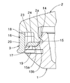
【図12】上記フックピースの要部の斜視図である。
【図13】上記フックピースの側面図である。
【図14】上記フックピースの断面図である。
【図15】蓋体の側面図である。
【図16】上記蓋体の正面図である。
【図17】上記フックピースを前側凹部に装着した状態を示す平面図である。
【図18】上記フックピースを前側凹部に装着した状態を示す断面図である。
【図19】上記化粧料容器の作用を示す平面図である。
【図20】上記化粧料容器の作用を示す断面図である。
【図21】従来例を示す斜視図である。
【図22】他の従来例を示す正面図である。
【図23】上記他の従来例に用いるフックピースの平面図である。
【図24】上記他の従来例の要部の断面図である。
【図25】上記他の従来例の前側凹部にフックピースを装着した状態を示す平面図である。
【符号の説明】
1 容器本体
3 フックピース
12 前側凹部
12a 奥壁面
12b 当接面
13 奥側凹部
14 係合用突条
17 係合板部[0001]
BACKGROUND OF THE INVENTION
The present invention relates to a cosmetic container such as a compact.
[0002]
[Prior art]
Conventionally, as a cosmetic container such as a compact, as shown in FIG. 21, a
[0003]
However, when the
[0004]
[Patent Document 1]
JP 2002-58525 A (paragraph numbers [0009] to [0017])
[0005]
[Problems to be solved by the invention]
However, in this cosmetic container, the
[0006]
The present invention has been made in view of such circumstances, and the structure of the operation piece is simple, and the range of the operation piece that can be pressed without changing the operation piece simply by appropriately changing the container body is provided. The purpose is to provide a cosmetic container that can be changed as appropriate.
[0007]
[Means for Solving the Problems]
In order to achieve the above object, a cosmetic container according to the present invention includes a container body, a lid hinged to the rear end of the container body, and a wide operation piece having flexibility, An engaging portion is provided at the front end of the lid, and a wide notch recess for disposing the operation piece is formed at the front end of the container body, and the rear surface of the operation piece is formed on the back wall surface of the notch recess. A pair of left and right operation piece support surfaces that are in contact with each other, and a portion of the back wall surface sandwiched between these operation piece support surfaces is notched rearward to provide a wide back notch recess, and The back-side cutout recess is provided with a pair of left and right tapered surfaces inclined inwardly toward the back side, and a back end surface sandwiched between the two tapered surfaces, and the lid body is provided on the back end surface. An engaged portion that is detachably engaged with the engaging portion is provided, and is opposed to the engaged portion. The portion of the operation piece, to form a release portion which can release the engagement of the engagement portion of the engaging portion and the container body of the lid, the operation member corresponding to the recess-away rear side cut of the container body With the both end portions of the operation piece being in contact with the pair of left and right operation piece support surfaces of the rear notch recess, the engagement portion is engaged with the release portion of the operation piece by bending the operation piece portion backward. The configuration is such that the configuration is canceled.
[0008]
That is, the cosmetic container of the present invention includes a container main body, a lid, and a wide operation piece having flexibility, and the wide operation piece is disposed at the front end of the container main body. A notch recess is formed, and on the back wall surface of the notch recess is formed a pair of left and right operation piece support surfaces that contact the rear surface of the operation piece, and the back wall surface sandwiched between these operation piece support surfaces. This portion is cut out rearward to provide a wide back cutout recess including a pair of left and right tapered surfaces . Then, in a state where both end portions of the operation piece corresponding to the back notch recess are in contact with the pair of left and right operation piece support surfaces of the back notch recess, the operation piece portion is bent backward. Accordingly, the engagement between the engagement portion of the lid and the engaged portion of the rear-side notch recess of the container body is released by the release portion formed on the operation piece. According to this configuration, by pressing a wide range of the operation piece, it is possible to bend the part of the operation piece corresponding to the wide back notch recess including the tapered surface , even in elderly women, The lid can be opened reliably with a small force. In addition, as described above, since the portion of the operation piece corresponding to the back notch recess is bent, when changing the range of the operation piece that can be pressed as appropriate, the change is made accordingly. It is only necessary to change the formation position and the lateral width of the rear side notch recess. Therefore, it is only necessary to change the container body, and there is no need to change the operation piece.
[0009]
In the present invention, an inclined surface that descends toward the front is formed on the lower portion of the engaged portion of the back end surface of the back notch recess, and the operation piece corresponding to the inclined surface By extending the push-up part to the rear via the elastic connecting part, the release part of the operation piece is formed, and the push-up part of the operation piece is slidably disposed on the inclined surface of the back notch recess, By bending the operation piece rearward, the push-up portion of the operation piece is slid upward along the inclined surface of the recessed portion on the back side, and the engagement portion of the lid is pushed up from below to engage the engagement member. When configured to release the engagement, the engaging portion of the lid can be lifted from below by the push-up portion of the operation piece, and the engagement can be released with a small force.
[0010]
In the present invention, when the lateral width of the operation piece is set in a range of 75 to 95% of the lateral width of the container body, the lateral width of the operation piece can be formed very wide.
[0011]
In the present invention, when the width of the rear notch recess is set in the range of 40 to 90% of the width of the operation piece, and preferably in the range of 55 to 65%, the operation piece is Not only can it be pressed reliably, but there is no possibility of accidentally opening the lid. In other words, as is found from the results of many experiments, when the width of the operation piece is less than 40% of the width of the container body, an elderly woman or the like presses the operation piece with a single operation. When the number of cases where the operation cannot be performed increases and exceeds 90%, the operation piece easily hits the surrounding objects, and the lid is often inadvertently opened.
[0012]
DETAILED DESCRIPTION OF THE INVENTION
Next, embodiments of the present invention will be described in detail with reference to the drawings.
[0013]
1 and 2 show one embodiment of the cosmetic container of the present invention. In these drawings, 1 is a container body, 2 is a lid that covers the upper surface of the
[0014]
Moreover, as shown in FIGS. 5-7, the said container
[0015]
The
[0016]
As shown in FIGS. 8 to 12, the
[0017]
The
[0018]
The
[0019]
Then, the width of the
[0020]
As shown in FIGS. 15 and 16, the
[0021]
In the above configuration, when the lid is opened, the center portion of the
[0022]
Thus, in the said embodiment, since the horizontal width of the
[0023]
【The invention's effect】
As described above, according to the cosmetic container of the present invention, the wide notch recess including the pair of left and right tapered surfaces is provided in the wide notch recess formed at the front end of the container body, and the notch A flexible operation piece having flexibility is disposed in the recess, and both ends thereof are pressed in a state where they are in contact with the pair of left and right operation piece support surfaces of the back notch recess, and the back By bending the portion of the operation piece corresponding to the side cutout recess to the back side, the engagement between the engagement portion of the lid and the engaged portion of the back cutout recess can be released. . For this reason, an elderly woman etc. can open reliably with a small force by pressing the wide range of an operation piece. In addition, as described above, since the portion of the operation piece corresponding to the back notch recess is bent, when changing the range of the operation piece that can be pressed as appropriate, the change is made accordingly. It is only necessary to change the formation position and the lateral width of the rear side notch recess. Therefore, it is only necessary to change the container body, and there is no need to change the operation piece.
[0024]
In the present invention, an inclined surface that descends toward the front is formed on the lower portion of the engaged portion of the back end surface of the back notch recess, and the operation piece corresponding to the inclined surface By extending the push-up part to the rear via the elastic connecting part, the release part of the operation piece is formed, and the push-up part of the operation piece is slidably disposed on the inclined surface of the back notch recess, By bending the operation piece rearward, the push-up portion of the operation piece is slid upward along the inclined surface of the recessed portion on the back side, and the engagement portion of the lid is pushed up from below to engage the engagement member. When configured to release the engagement, the engaging portion of the lid can be lifted from below by the push-up portion of the operation piece, and the engagement can be released with a small force.
[0025]
In the present invention, when the lateral width of the operation piece is set in a range of 75 to 95% of the lateral width of the container body, the lateral width of the operation piece can be formed very wide.
[0026]
In the present invention, when the width of the rear notch recess is set in the range of 40 to 90% of the width of the operation piece, and preferably in the range of 55 to 65%, the operation piece is Not only can it be pressed reliably, but there is no possibility of accidentally opening the lid. In other words, as is found from the results of many experiments, when the width of the operation piece is less than 40% of the width of the container body, an elderly woman or the like presses the operation piece with a single operation. When the number of cases where the operation cannot be performed increases and exceeds 90%, the operation piece easily hits the surrounding objects, and the lid is often inadvertently opened.
[Brief description of the drawings]
FIG. 1 is a front view showing an embodiment of a cosmetic container according to the present invention.
FIG. 2 is a side view of the cosmetic container.
FIG. 3 is a side view of the container body.
FIG. 4 is a plan view of the cosmetic container.
FIG. 5 is a plan view of the main part of the container body.
FIG. 6 is a front view of the main part of the cosmetic container.
FIG. 7 is a cross-sectional view of a main part of the container body.
FIG. 8 is a plan view of a hook piece.
FIG. 9 is a view of the hook piece as seen from the back.
FIG. 10 is a front view of the hook piece.
FIG. 11 is a view of the hook piece as viewed from below.
FIG. 12 is a perspective view of a main part of the hook piece.
FIG. 13 is a side view of the hook piece.
FIG. 14 is a cross-sectional view of the hook piece.
FIG. 15 is a side view of the lid.
FIG. 16 is a front view of the lid body.
FIG. 17 is a plan view showing a state in which the hook piece is mounted in the front recess.
FIG. 18 is a cross-sectional view showing a state where the hook piece is mounted in the front recess.
FIG. 19 is a plan view showing the operation of the cosmetic container.
FIG. 20 is a cross-sectional view showing the operation of the cosmetic container.
FIG. 21 is a perspective view showing a conventional example.
FIG. 22 is a front view showing another conventional example.
FIG. 23 is a plan view of a hook piece used in the other conventional example.
FIG. 24 is a cross-sectional view of a main part of the other conventional example.
FIG. 25 is a plan view showing a state in which a hook piece is mounted in the front concave portion of the other conventional example.
[Explanation of symbols]
DESCRIPTION OF
Claims (4)
Priority Applications (1)
| Application Number | Priority Date | Filing Date | Title |
|---|---|---|---|
| JP2003057209A JP4328111B2 (en) | 2003-03-04 | 2003-03-04 | Cosmetic container |
Applications Claiming Priority (1)
| Application Number | Priority Date | Filing Date | Title |
|---|---|---|---|
| JP2003057209A JP4328111B2 (en) | 2003-03-04 | 2003-03-04 | Cosmetic container |
Publications (2)
| Publication Number | Publication Date |
|---|---|
| JP2004261504A JP2004261504A (en) | 2004-09-24 |
| JP4328111B2 true JP4328111B2 (en) | 2009-09-09 |
Family
ID=33120689
Family Applications (1)
| Application Number | Title | Priority Date | Filing Date |
|---|---|---|---|
| JP2003057209A Expired - Fee Related JP4328111B2 (en) | 2003-03-04 | 2003-03-04 | Cosmetic container |
Country Status (1)
| Country | Link |
|---|---|
| JP (1) | JP4328111B2 (en) |
-
2003
- 2003-03-04 JP JP2003057209A patent/JP4328111B2/en not_active Expired - Fee Related
Also Published As
| Publication number | Publication date |
|---|---|
| JP2004261504A (en) | 2004-09-24 |
Similar Documents
| Publication | Publication Date | Title |
|---|---|---|
| FR2824243A1 (en) | Puff retrieving structure for face powder compact has puff withdrawal device with operation portion provided at end of tool portion to raise front end of baseplate | |
| JP4328111B2 (en) | Cosmetic container | |
| JPS5836328Y2 (en) | compact container | |
| JPH07206055A (en) | Container for wet tissue paper | |
| JP2002058525A (en) | Cosmetic case | |
| KR200253674Y1 (en) | face powder compact | |
| KR101534467B1 (en) | Cosmetic case | |
| JP3850477B2 (en) | Cosmetic container | |
| JP3850476B2 (en) | Cosmetic container | |
| JPS5939928Y2 (en) | compact container | |
| JP4293654B2 (en) | Cosmetic container | |
| JPH053138Y2 (en) | ||
| JP3823260B2 (en) | Compact container | |
| JPH0446658Y2 (en) | ||
| JPH0515842Y2 (en) | ||
| JP3017844U (en) | Compact container | |
| JPH034170Y2 (en) | ||
| JP3060258U (en) | Container structure | |
| JP2537690Y2 (en) | compact | |
| KR200184532Y1 (en) | Tissue case | |
| JP3681422B2 (en) | Cosmetic container | |
| JPH0513290Y2 (en) | ||
| JP4778750B2 (en) | container | |
| JPH0710647Y2 (en) | Cosmetics storage container | |
| JPH0630101Y2 (en) | Makeup compact |
Legal Events
| Date | Code | Title | Description |
|---|---|---|---|
| A621 | Written request for application examination |
Free format text: JAPANESE INTERMEDIATE CODE: A621 Effective date: 20060217 |
|
| A977 | Report on retrieval |
Free format text: JAPANESE INTERMEDIATE CODE: A971007 Effective date: 20090127 |
|
| A131 | Notification of reasons for refusal |
Free format text: JAPANESE INTERMEDIATE CODE: A131 Effective date: 20090303 |
|
| A521 | Written amendment |
Free format text: JAPANESE INTERMEDIATE CODE: A523 Effective date: 20090501 |
|
| TRDD | Decision of grant or rejection written | ||
| A01 | Written decision to grant a patent or to grant a registration (utility model) |
Free format text: JAPANESE INTERMEDIATE CODE: A01 Effective date: 20090602 |
|
| A01 | Written decision to grant a patent or to grant a registration (utility model) |
Free format text: JAPANESE INTERMEDIATE CODE: A01 |
|
| A61 | First payment of annual fees (during grant procedure) |
Free format text: JAPANESE INTERMEDIATE CODE: A61 Effective date: 20090612 |
|
| FPAY | Renewal fee payment (event date is renewal date of database) |
Free format text: PAYMENT UNTIL: 20120619 Year of fee payment: 3 |
|
| R150 | Certificate of patent or registration of utility model |
Free format text: JAPANESE INTERMEDIATE CODE: R150 |
|
| FPAY | Renewal fee payment (event date is renewal date of database) |
Free format text: PAYMENT UNTIL: 20130619 Year of fee payment: 4 |
|
| FPAY | Renewal fee payment (event date is renewal date of database) |
Free format text: PAYMENT UNTIL: 20140619 Year of fee payment: 5 |
|
| LAPS | Cancellation because of no payment of annual fees |