JP4327272B2 - Casing for appliances, especially for automotive sensors - Google Patents
Casing for appliances, especially for automotive sensors Download PDFInfo
- Publication number
- JP4327272B2 JP4327272B2 JP24825598A JP24825598A JP4327272B2 JP 4327272 B2 JP4327272 B2 JP 4327272B2 JP 24825598 A JP24825598 A JP 24825598A JP 24825598 A JP24825598 A JP 24825598A JP 4327272 B2 JP4327272 B2 JP 4327272B2
- Authority
- JP
- Japan
- Prior art keywords
- casing
- bush
- fixing
- hole
- holes
- Prior art date
- Legal status (The legal status is an assumption and is not a legal conclusion. Google has not performed a legal analysis and makes no representation as to the accuracy of the status listed.)
- Expired - Lifetime
Links
Images


Classifications
-
- B—PERFORMING OPERATIONS; TRANSPORTING
- B60—VEHICLES IN GENERAL
- B60R—VEHICLES, VEHICLE FITTINGS, OR VEHICLE PARTS, NOT OTHERWISE PROVIDED FOR
- B60R16/00—Electric or fluid circuits specially adapted for vehicles and not otherwise provided for; Arrangement of elements of electric or fluid circuits specially adapted for vehicles and not otherwise provided for
- B60R16/02—Electric or fluid circuits specially adapted for vehicles and not otherwise provided for; Arrangement of elements of electric or fluid circuits specially adapted for vehicles and not otherwise provided for electric constitutive elements
- B60R16/023—Electric or fluid circuits specially adapted for vehicles and not otherwise provided for; Arrangement of elements of electric or fluid circuits specially adapted for vehicles and not otherwise provided for electric constitutive elements for transmission of signals between vehicle parts or subsystems
- B60R16/0239—Electronic boxes
-
- B—PERFORMING OPERATIONS; TRANSPORTING
- B60—VEHICLES IN GENERAL
- B60R—VEHICLES, VEHICLE FITTINGS, OR VEHICLE PARTS, NOT OTHERWISE PROVIDED FOR
- B60R11/00—Arrangements for holding or mounting articles, not otherwise provided for
-
- H—ELECTRICITY
- H05—ELECTRIC TECHNIQUES NOT OTHERWISE PROVIDED FOR
- H05K—PRINTED CIRCUITS; CASINGS OR CONSTRUCTIONAL DETAILS OF ELECTRIC APPARATUS; MANUFACTURE OF ASSEMBLAGES OF ELECTRICAL COMPONENTS
- H05K5/00—Casings, cabinets or drawers for electric apparatus
- H05K5/02—Details
- H05K5/0217—Mechanical details of casings
-
- B—PERFORMING OPERATIONS; TRANSPORTING
- B60—VEHICLES IN GENERAL
- B60R—VEHICLES, VEHICLE FITTINGS, OR VEHICLE PARTS, NOT OTHERWISE PROVIDED FOR
- B60R21/00—Arrangements or fittings on vehicles for protecting or preventing injuries to occupants or pedestrians in case of accidents or other traffic risks
- B60R21/01—Electrical circuits for triggering passive safety arrangements, e.g. airbags, safety belt tighteners, in case of vehicle accidents or impending vehicle accidents
- B60R2021/01006—Mounting of electrical components in vehicles
-
- Y—GENERAL TAGGING OF NEW TECHNOLOGICAL DEVELOPMENTS; GENERAL TAGGING OF CROSS-SECTIONAL TECHNOLOGIES SPANNING OVER SEVERAL SECTIONS OF THE IPC; TECHNICAL SUBJECTS COVERED BY FORMER USPC CROSS-REFERENCE ART COLLECTIONS [XRACs] AND DIGESTS
- Y10—TECHNICAL SUBJECTS COVERED BY FORMER USPC
- Y10S—TECHNICAL SUBJECTS COVERED BY FORMER USPC CROSS-REFERENCE ART COLLECTIONS [XRACs] AND DIGESTS
- Y10S220/00—Receptacles
- Y10S220/04—Bushings
Description
【0001】
【発明の属する技術分野】
本発明は、組み付け面に固定するための器具、特に自動車のセンサのためのケーシングであって、ケーシングに2つの固定フランジが設けられていて、これらの固定フランジが、ねじ込みボルトを貫通させるための、前記組み付け面に対して直角に延びる各1つの貫通孔を有しており、これらの貫通孔は、固定フランジを貫通するブシュの内側に位置していて、ブシュが金属から成っていて、ケーシングの材料によって、射出成形されて埋め込まれている形式のものに関する。
【0002】
【従来の技術】
このような形式の器具のためのケーシングは既に公知である(ドイツ連邦共和国特許第4211615号明細書参照)。この公知の器具ケーシングでは、薄板から成るケーシングシェルが、固定フランジ内にまで続いていて、ここで円形の横断面のブシュを形成するように巻かれる。このブシュは周面側で、プラスチックから成るケーシングの材料によって射出成形されて埋め込まれている。適合してこのブシュに収容されたねじ込みボルト又はこれに類するような固定手段は、器具のための組み付け面に少ない許容誤差で配置されなければならない。これに対して、固定手段とブシュとの間の比較的大きな遊びにより、器具を組み付け面に相対的に不正確な位置で取り付ける恐れがある。
【0003】
ドイツ連邦共和国実用新案第9111106号明細書によれば、器具ケーシングの固定フランジに設けられた、固定手段を貫通させるために働く2つの貫通孔のうちの1つが長孔として形成されていることが公知である。これにより、比較的大きな固定手段の間隔の誤差を補償することができる。
【0004】
【発明が解決しようとする課題】
冒頭で述べた形式の器具のためのケーシングを改良して、固定手段の間の間隔の誤差が大きい場合でも、器具を組み付け面に正確に固定することができ、ブシュに加えられる緊定力を正確に構成部分に伝えることのできるような、器具のためのケーシングを提供することである。
【0005】
【課題を解決するための手段】
この課題を解決するために本発明の構成では、両貫通孔が長孔として形成されていて、該長孔の幅が、ねじ込みボルトの直径に相当しており、ブシュが、貫通孔の外輪郭に適合していて、該貫通孔を半径方向の間隔をおいて取り囲んでおり、ブシュには周面側で、凹部及び又は貫通孔が設けられていて、これらの凹部及び又は貫通孔は、ケーシングの材料によって充填されており、ブシュが内周面側で、固定フランジの下面に対して、軸方向長さの所定の部分でケーシングの材料から離されているようにした。
【0006】
【発明の効果】
本発明による器具のためのケーシングは、両固定手段の間の間隔が、極めて大きな誤差を有していても、器具を組み付け面に固定することができるという利点を有している。さらにこの器具は、各固定フランジの長孔の形の貫通孔の長い方の軸線に対して横方向でほぼ遊びなしに固定手段に支持されていて、これにより少なくとも長孔の横方向において、器具を正確な位置で配置することができる。この場合、各固定フランジにおける長孔の正確な形状及び寸法の構成は、ケーシングの射出成形工具によって得られる。一方ブシュは、固定手段のねじヘッド又はナットからブシュに加えられる緊定力を、器具のための組み付け面を有した構成部分に伝えるという課題を有している。ブシュとケーシング材料とが内部で密に形状接続的に結合していることにより、この結合の解離が回避され、器具に加えられる力を構成部分に確実に伝えることができる。さらに、ブシュの下側が被覆されていないことにより、例えば、溶接・ねじ込みボルトを使用する際に生じる溶接凸部又はねじ込みボルトのフランジを収容することができる。このような空間は、ケーシングのための射出成形工具の適宜に成形された中子により形成可能であって、この中子は同時に、射出成形過程においてブシュを位置固定するために用いられる。
【0007】
請求項2以下に記載された手段により、請求項1に記載の器具のためのケーシングの別の構成及び有利な構成が得られる。
【0008】
請求項2記載の構成により、固定点の間の組み付け面に位置する非平坦性によって、器具のためのケーシングの負荷又は変形がほぼ回避される。
【0009】
請求項3記載の別の構成により、旋盤加工部品として形成されたブシュと比して有利なコストが得られる。
【0010】
請求項4の構成により、固定手段の間隔の誤差が特に大きい場合でも器具ケーシングを固定することができ、又は、固定手段の間隔の誤差が小さい場合には、前記の軸線の方向で限定された摺動をすることにより器具のためのケーシングを方向づけることができる。
【0011】
請求項5による別の構成によれば、一方の固定手段の軸を中心にして、器具のためのケーシングを所定のように旋回させることもできる。これにより、組み付け面を有する構成部分に関して器具の所要の配向を調節することができ、次いで器具を固定することができる。
【0012】
【発明の実施の形態】
次に図面につき本発明の実施の形態を詳しく説明する。
【0013】
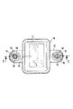
符号10で図示した器具、例えば自動車のためのセンサは、プラスチックから射出成形によって成形されたケーシング11を有している。このケーシング11は、互いに反対側の面に一体成形された固定フランジ12,13を備えている(図1及び図2参照)。これらの固定フランジ12,13は、ケーシング11の下面と同様に、共通の平面によって制限されている。固定フランジ12,13には、長孔として形成された各1つの貫通孔14が加工成形されている。固定フランジ12,13の貫通孔14は、固定手段を受容するために規定されている。固定手段とはこの実施例では、溶接・ねじ込みボルト15である。これらの溶接・ねじ込みボルト15は、構成部分17、例えば自動車の車体構成部分の組み付け面16から直角に、互いに平行に延びる軸線を有して延びている。この組み付け面16に対して直角に延びる貫通孔14は、固定フランジ12,13を貫通するブシュ18の内側に位置している。貫通孔14は、ねじ込みボルト15の直径に相当する幅と、この幅よりも大きな長さとを有して形成されており、ブシュ18は、各貫通孔14を均一な半径方向の間隔をおいて取り囲んでいる。
【0014】
図4に立体的に図示されたブシュ18は、金属から成っていて、薄板ストリップを、固定フランジ12,13の貫通孔14に相応する形状になるように巻いて形成されている。ブシュ18の壁には貫通孔21が設けられている。これらの貫通孔21の間には、外周面に分配されるようにエンボス加工された凹部22が位置している。この実施例では、3つの貫通孔21と6つの凹部22が設けられている。ブシュ18は、固定フランジ12,13の高さに相当する長さよりも大きな軸方向の長さを有している。図2から明らかであるように、それぞれのブシュ18は、固定フランジ12,13の上面と同一平面に位置している。これに対しブシュ18は、固定フランジ12,13の下面を僅かに越えて延びている。即ち各ブシュ18は、その軸方向のほぼ全長さでケーシング11の材料によって外周面側で取り囲まれている。ケーシング材料は、固定フランジ12,13の両ブシュ18を、内周面側でも、軸方向長さの大部分で取り囲んでいる。しかし固定フランジ12,13の下面に対しては空間23が残されている。外周面側及び内周面側に位置するケーシング材料は、ブシュ18に設けられた貫通孔21に入り込み、ブシュ18の凹部22を充填する。これによりブシュ18と固定フランジ12,13との間の形状接続的な緊密な結合が形成される。
【0015】
器具10はブシュ18の端面でしか、構成部分17の組み付け面16に支持されていない。他の部分では、ケーシング11及び固定フランジ12,13の下面との間には僅かな間隔が置かれている。構成部分17に溶接されたねじ込みボルト15は溶接凸部26を有している。この溶接凸部26は、各ブシュ18の内側の十分な大きさの空間23に収容されている。外径が適合して固定フランジ12,13の各貫通孔14に進入するねじ込みボルト15には、押圧されるフランジ28を備えた六角ナット27がねじ込まれている。六角ナット27はフランジ28で、ブシュ18の露出された端面に係合する。従ってねじ結合の緊定力は、ブシュ18からしか構成部分17に伝動されない。
【0016】
図1に示したように、両ブシュ18はその外輪郭の長手方向軸線31に関して、ケーシング11の固定フランジ12,13の貫通孔14と同軸的に向けられている。これにより、両ねじ込みボルト15の大きな間隔誤差にも関わらず、器具10を構成部分に固定することができる。このことは、固定フランジ12,13の貫通孔14におけるねじ込みボルト横断面の位置からわかる。ねじ込みボルト15の、間隔の許容誤差が使い尽くされていない場合は、ケーシング10を所定の範囲で長手方向軸線31の方向にずらして、構成部分17に固定することができる。ブシュ18が選択された寸法であれば、ねじ込みボルト15がいかなる許容誤差位置にある場合でも、ナット27のフランジ28は、対応するブシュ18のほぼ全端面に係合する。
【0017】
図3によると、ケーシング11の形状のもとで、固定フランジ12における貫通孔14とブシュ18だけが、固定フランジ12における長手方向軸線31が、固定フランジ13における長手方向軸線31に対して90度ずらされて向けられているように配向されていることが示されている。両貫通孔14がこのように配向されていると、器具10を固定フランジ13のねじ込みボルト15を中心として僅かに旋回させることができ、構成部分17に固定することができる。
【図面の簡単な説明】
【図1】2つの固定フランジを備えた器具の平面図である。
【図2】図1のII−II線に沿って断面した固定フランジを備えた器具の側方図である。
【図3】異なる構成の固定フランジの平面図である。
【図4】固定フランジ内に加工成形されたブシュを拡大して立体的に示した図である。
【符号の説明】
10 器具、 11 ケーシング、 12,13 固定フランジ、 14 貫通孔、 15 ねじ込みボルト、 16 組み付け面、 17 構成部分、 18 ブシュ、 21 貫通孔、 22 凹部、 23 空間、 26 溶接凸部、 27 六角ナット、 28 フランジ、 31 長手方向軸線[0001]
BACKGROUND OF THE INVENTION
The present invention is a casing for an appliance for fixing to an assembly surface, in particular an automobile sensor, wherein the casing is provided with two fixing flanges for passing through the screw bolts. Each of the through holes extending at right angles to the assembly surface, and these through holes are located inside the bushes that pass through the fixing flange, and the bushes are made of metal, and the casing. It is related to the type that is injection molded and embedded by the material.
[0002]
[Prior art]
Casings for devices of this type are already known (cf. DE 42 11 615). In this known instrument casing, a thin casing casing continues into the fixed flange, where it is wound to form a circular cross-section bush. The bush is injection-molded and embedded with a casing material made of plastic on the peripheral surface side. Screwing bolts or similar fastening means that are accommodated in the bushing must be arranged with little tolerance on the assembly surface for the instrument. On the other hand, the relatively large play between the fixing means and the bush may cause the instrument to be attached to the assembly surface at a relatively inaccurate position.
[0003]
According to German Utility Model No. 9111106, one of the two through holes provided in the fixing flange of the instrument casing for penetrating the fixing means is formed as a long hole. It is known. Thereby, it is possible to compensate for a relatively large error in the interval of the fixing means.
[0004]
[Problems to be solved by the invention]
The casing for an appliance of the type mentioned at the beginning has been improved so that the appliance can be accurately fixed to the assembly surface even if the spacing error between the fixing means is large, and the tightening force applied to the bushing can be reduced. It is to provide a casing for the instrument that can be accurately transmitted to the component.
[0005]
[Means for Solving the Problems]
In order to solve this problem, in the configuration of the present invention, both the through holes are formed as long holes, the width of the long holes corresponds to the diameter of the screw bolt, and the bush is the outer contour of the through hole. And the bush is provided with a recess and / or a through hole on the circumferential surface side, and the recess and / or the through hole is formed in the casing. The bush is made to be separated from the casing material at a predetermined portion of the axial length with respect to the lower surface of the fixed flange on the inner peripheral surface side.
[0006]
【The invention's effect】
The casing for the device according to the invention has the advantage that the device can be fixed to the assembly surface even if the spacing between the two fixing means has a very large error. Furthermore, the device is supported by the fixing means in the transverse direction with respect to the longer axis of the through-hole in the form of a slot in each fixing flange, with substantially no play, so that at least in the lateral direction of the slot. Can be placed at an accurate position. In this case, the configuration of the exact shape and dimensions of the elongated holes in each fixed flange is obtained by the casing injection molding tool. On the other hand, the bush has the problem of transmitting the tightening force applied to the bush from the screw head or nut of the fixing means to a component having an assembly surface for the instrument. Due to the tightly shape-coupled connection between the bushing and the casing material, disengagement of this connection is avoided and the force applied to the instrument can be reliably transmitted to the component. Further, since the lower side of the bush is not covered, it is possible to accommodate, for example, a welding convex portion or a flange of the screw bolt generated when using the welding / screw bolt. Such a space can be formed by a suitably shaped core of an injection molding tool for the casing, which core is used at the same time for fixing the bushing in the injection molding process.
[0007]
By means as defined in claim 2 and below, further and advantageous configurations of the casing for the device according to
[0008]
Due to the non-flatness located on the assembly surface between the fixed points, the load or deformation of the casing for the instrument is substantially avoided.
[0009]
According to another configuration of claim 3, an advantageous cost can be obtained as compared with a bush formed as a lathe processed part.
[0010]
According to the configuration of claim 4, the instrument casing can be fixed even when the error of the fixing means interval is particularly large, or when the error of the fixing means interval is small, the direction of the axis is limited. By sliding, the casing for the instrument can be oriented.
[0011]
According to another configuration of the fifth aspect, the casing for the instrument can be swung in a predetermined manner around the axis of the one fixing means. This allows the required orientation of the instrument to be adjusted with respect to the component having the assembly surface and then the instrument can be secured.
[0012]
DETAILED DESCRIPTION OF THE INVENTION
Next, embodiments of the present invention will be described in detail with reference to the drawings.
[0013]
A sensor, for example an automobile, illustrated by
[0014]
The
[0015]
The
[0016]
As shown in FIG. 1, both
[0017]
According to FIG. 3, under the shape of the
[Brief description of the drawings]
FIG. 1 is a plan view of an instrument with two fixation flanges.
FIG. 2 is a side view of an instrument with a fixing flange taken along line II-II in FIG.
FIG. 3 is a plan view of a fixing flange having a different configuration.
FIG. 4 is an enlarged three-dimensional view of a bush processed and formed in a fixed flange.
[Explanation of symbols]
DESCRIPTION OF
Claims (5)
(イ)ケーシング(11)に2つの固定フランジ(12,13)が設けられていて、これらの固定フランジ(12,13)が、ねじ込みボルト(15)を貫通させるための、前記組み付け面(16)に対して直角に延びる各1つの貫通孔(14)を有しており、
(ロ)これらの貫通孔(14)は、固定フランジ(12,13)を貫通するブシュ(18)の内側に位置していて、
(ハ)ブシュ(18)が金属から成っていて、ケーシング(11)の材料によって、射出成形されて埋め込まれている形式のものにおいて、
(ニ)前記両貫通孔(14)が長孔として形成されていて、該長孔の幅が、ねじ込みボルト(15)の直径に相当しており、
(ホ)ブシュ(18)が、貫通孔(14)の外輪郭に適合していて、該貫通孔(14)を半径方向の間隔をおいて取り囲んでおり、
(ヘ)ブシュ(18)には周面側で、凹部(22)及び又は貫通孔(21)が設けられていて、これらの凹部(22)及び又は貫通孔(21)は、ケーシング(11)の材料によって充填されており、
(ト)ブシュ(18)が内周面側で、固定フランジ(12,13)の下面に対して、軸方向長さの所定の部分でケーシング(11)の材料から離されており、
(チ)固定フランジ(12,13)の下面に対して空間(23)が残されていることを特徴とする、器具、特に自動車のセンサのためのケーシング。An instrument (10) for fixing to an assembly surface (16), in particular a casing (11) for a sensor of an automobile,
(A) Two fixing flanges (12, 13) are provided in the casing (11), and these fixing flanges (12, 13) allow the screw bolts (15) to pass therethrough. Each through-hole (14) extending perpendicular to
(B) These through holes (14) are located inside the bushes (18) penetrating the fixing flanges (12, 13).
(C) In the type in which the bush (18) is made of metal and is injection-molded and embedded by the material of the casing (11),
(D) both the through holes (14) are formed as long holes, and the width of the long holes corresponds to the diameter of the screw bolt (15);
(E) the bushing (18) is adapted to the outer contour of the through hole (14) and surrounds the through hole (14) with a radial spacing;
(F) The bush (18) is provided with a recess (22) and / or a through hole (21) on the peripheral surface side, and the recess (22) and / or the through hole (21) is formed in the casing (11). Filled with material,
(G) The bush (18) is separated from the material of the casing (11) at a predetermined portion of the axial length with respect to the lower surface of the fixed flange (12, 13) on the inner peripheral surface side ,
(H) A casing for an appliance, in particular an automobile sensor, characterized in that a space (23) is left against the lower surface of the fixing flange (12, 13) .
Applications Claiming Priority (2)
| Application Number | Priority Date | Filing Date | Title |
|---|---|---|---|
| DE19738803.5A DE19738803B4 (en) | 1997-09-05 | 1997-09-05 | Housing for a device, in particular sensor for motor vehicles |
| DE19738803.5 | 1997-09-05 |
Publications (2)
| Publication Number | Publication Date |
|---|---|
| JPH11148985A JPH11148985A (en) | 1999-06-02 |
| JP4327272B2 true JP4327272B2 (en) | 2009-09-09 |
Family
ID=7841264
Family Applications (1)
| Application Number | Title | Priority Date | Filing Date |
|---|---|---|---|
| JP24825598A Expired - Lifetime JP4327272B2 (en) | 1997-09-05 | 1998-09-02 | Casing for appliances, especially for automotive sensors |
Country Status (4)
| Country | Link |
|---|---|
| US (1) | US6158609A (en) |
| JP (1) | JP4327272B2 (en) |
| CH (1) | CH692802A5 (en) |
| DE (1) | DE19738803B4 (en) |
Families Citing this family (15)
| Publication number | Priority date | Publication date | Assignee | Title |
|---|---|---|---|---|
| US6357561B2 (en) * | 1999-10-15 | 2002-03-19 | Stop Technologies Llc | Thermal expansion bushing in a metal matrix composite rotor |
| DE20112595U1 (en) * | 2001-07-31 | 2002-01-17 | Trw Automotive Electron & Comp | Housing for receiving a printed circuit board with electronic components |
| DE102004034290A1 (en) * | 2004-07-15 | 2007-01-11 | Siemens Ag | Sensor for motor vehicles |
| DE102004035805B4 (en) * | 2004-07-23 | 2006-12-14 | Siemens Ag | Housing for a device, in particular a sensor for motor vehicles |
| DE102004060614B4 (en) * | 2004-12-16 | 2009-08-13 | Continental Safety Engineering International Gmbh | Device for detecting a pedestrian impact and method for producing such a device |
| DE102005021717A1 (en) | 2005-05-11 | 2006-11-16 | Zf Friedrichshafen Ag | Sensor arrangement for tachometric sensor of automatic transmission for motor vehicle has spring that produces prestress force when sensor housing is forced against detent by projection |
| DE102005061889A1 (en) * | 2005-12-23 | 2007-07-05 | Robert Bosch Gmbh | Insert for an injection moulded component comprises at least one outer surface, a metallic corrosion protection layer and a sealing layer |
| DE102006024163A1 (en) * | 2006-05-22 | 2007-11-29 | Conti Temic Microelectronic Gmbh | Electrical assembly for a vehicle comprises a rigid connecting part arranged in/on a mounting flange in a housing, fixed to a support and connected in a mechanically rigid manner to a structure-borne noise/acceleration sensor |
| DE102006034504A1 (en) * | 2006-07-26 | 2008-01-31 | Conti Temic Microelectronic Gmbh | Electrical device for vehicle, has sensor for providing impact sound and/or acceleration signals, and mounting point designed as mounting flange formed by housing body, where sensor is arranged in proximity of mounting point |
| DE102007025859A1 (en) * | 2007-06-01 | 2008-12-04 | Conti Temic Microelectronic Gmbh | Control device for a motor vehicle |
| DE102008043657A1 (en) * | 2008-11-12 | 2010-05-20 | Robert Bosch Gmbh | Mounting arrangement for mounting part at vehicle, particularly for mounting of speed sensor on wheel suspension by screw joint, has opening on its plastic housing for guiding screw |
| AT510323B1 (en) * | 2010-09-06 | 2012-09-15 | Facc Ag | FIXING DEVICE |
| US20120261409A1 (en) * | 2011-04-14 | 2012-10-18 | Continental Automotive Systems, Inc. | Combined metal cover and anti-crush hole support |
| DE102018204658A1 (en) * | 2018-03-27 | 2019-10-02 | BSH Hausgeräte GmbH | Domestic appliance with a wall having an integrated, raised coupling element for coupling with a backing disposed thereon, and method |
| US11905082B2 (en) * | 2021-12-07 | 2024-02-20 | Owens-Brockway Glass Container Inc. | Child-resistant, pressurizable, and resealable package |
Family Cites Families (20)
| Publication number | Priority date | Publication date | Assignee | Title |
|---|---|---|---|---|
| US2734711A (en) * | 1956-02-14 | Tumbler holder | ||
| US973568A (en) * | 1909-10-26 | 1910-10-25 | Frank J Russell | Sign-receptacle fastening-eyelet. |
| US1738037A (en) * | 1928-05-21 | 1929-12-03 | Warner Corp | Spring bushing |
| US2586528A (en) * | 1946-05-06 | 1952-02-19 | Nat Formetal Company | Bushing |
| CH336474A (en) * | 1954-03-16 | 1959-02-28 | Siemens Ag | Housing for electrical apparatus, with insulated covered metal base plate and insulating cap |
| GB840464A (en) * | 1957-12-09 | 1960-07-06 | F C Blackwell & Company Ltd | Improvements in and relating to electrical switch, socket, junction or like boxes |
| US3698703A (en) * | 1970-11-23 | 1972-10-17 | Gen Tire & Rubber Co | Dual rate fluid damped elastomeric bushing |
| GB1547054A (en) * | 1976-04-22 | 1979-06-06 | Itt | Electrical connector assembly and method of making the same |
| SE422773B (en) * | 1978-09-15 | 1982-03-29 | Andersson Kurt Goeran | CARGO TRANSPORTING COUNTRY CONSISTING OF PORTABLE TO EACH FIXED LINKS |
| US4398647A (en) * | 1981-04-28 | 1983-08-16 | Perma Power Electronics, Inc. | Temporary mounting means for multiple outlet strip |
| DE3333892A1 (en) * | 1983-09-20 | 1985-04-04 | Robert Bosch Gmbh, 7000 Stuttgart | DISTRIBUTOR RATED FOR IGNITION DISTRIBUTION IN AN INTERNAL COMBUSTION ENGINE |
| DE3400870A1 (en) * | 1984-01-12 | 1985-07-25 | Vdo Adolf Schindling Ag, 6000 Frankfurt | INDUCTIVE |
| DE9111106U1 (en) | 1991-09-07 | 1993-01-07 | Robert Bosch Gmbh, 7000 Stuttgart, De | |
| GB2262000B (en) * | 1991-11-28 | 1995-06-07 | Hawke Cable Glands Ltd | Junction box |
| DE4211615C2 (en) | 1992-04-07 | 1994-09-22 | Bosch Gmbh Robert | Measuring device for determining an angle of rotation |
| US5182696A (en) * | 1992-06-08 | 1993-01-26 | Her Jern Shong | Distributor for television sets |
| US5335642A (en) * | 1992-09-03 | 1994-08-09 | Ford Motor Company | Ignition coil |
| DE4404957C2 (en) * | 1994-02-17 | 2003-08-21 | Bosch Gmbh Robert | Ignition coil for an internal combustion engine |
| US5801330A (en) * | 1995-02-09 | 1998-09-01 | Robert Bosch Gmbh | Housing for an electrical device having spring means |
| US5690879A (en) * | 1995-07-25 | 1997-11-25 | Solid Golf, Inc. | Method for injection molding a golf club body |
-
1997
- 1997-09-05 DE DE19738803.5A patent/DE19738803B4/en not_active Expired - Lifetime
-
1998
- 1998-07-10 US US09/113,475 patent/US6158609A/en not_active Expired - Lifetime
- 1998-08-21 CH CH01721/98A patent/CH692802A5/en not_active IP Right Cessation
- 1998-09-02 JP JP24825598A patent/JP4327272B2/en not_active Expired - Lifetime
Also Published As
| Publication number | Publication date |
|---|---|
| JPH11148985A (en) | 1999-06-02 |
| CH692802A5 (en) | 2002-10-31 |
| US6158609A (en) | 2000-12-12 |
| DE19738803A1 (en) | 1999-03-11 |
| DE19738803B4 (en) | 2018-05-24 |
Similar Documents
| Publication | Publication Date | Title |
|---|---|---|
| JP4327272B2 (en) | Casing for appliances, especially for automotive sensors | |
| JPH1016573A (en) | Engine mount bracket | |
| US4715648A (en) | Arrangement for increasing the body width at wheel housings of a vehicle | |
| US6427356B1 (en) | Mountable centering element and arrangement for measuring, or determining the position of a hole or a bolt | |
| JP2005106084A (en) | Connecting structure between rotary shaft and metal plate and method of connecting therebetween | |
| EP1439081A1 (en) | Connection between vehicle axle and carrier arm | |
| JP2001152966A (en) | Resin cylinder head cover | |
| JPH09104298A (en) | Divided bumper structural body | |
| US3918322A (en) | Snap-in lever assembly | |
| JPH0214556Y2 (en) | ||
| JP2833173B2 (en) | Member structure | |
| JPH0357153Y2 (en) | ||
| JPH10169620A (en) | Position adjusting device | |
| JPH0248138Y2 (en) | ||
| JPH0356106Y2 (en) | ||
| JPS6011292Y2 (en) | Automotive telltale lens mounting device | |
| JPH0439452Y2 (en) | ||
| KR0129083Y1 (en) | Nut for welding | |
| JPH0639148Y2 (en) | Automotive torsion bar mounting device | |
| JPH0331636Y2 (en) | ||
| JP3694244B2 (en) | Piping fixing tool | |
| JP2507220Y2 (en) | Structure for holding and fixing pipes with clamp members | |
| JPH0338501Y2 (en) | ||
| JPH077252Y2 (en) | Pipe fixing bracket fixture | |
| KR0118008B1 (en) | A clip-nut for attaching number plate to bumper in a vehicle |
Legal Events
| Date | Code | Title | Description |
|---|---|---|---|
| A621 | Written request for application examination |
Free format text: JAPANESE INTERMEDIATE CODE: A621 Effective date: 20050902 |
|
| A131 | Notification of reasons for refusal |
Free format text: JAPANESE INTERMEDIATE CODE: A131 Effective date: 20081114 |
|
| A601 | Written request for extension of time |
Free format text: JAPANESE INTERMEDIATE CODE: A601 Effective date: 20090213 |
|
| A602 | Written permission of extension of time |
Free format text: JAPANESE INTERMEDIATE CODE: A602 Effective date: 20090218 |
|
| A601 | Written request for extension of time |
Free format text: JAPANESE INTERMEDIATE CODE: A601 Effective date: 20090316 |
|
| A602 | Written permission of extension of time |
Free format text: JAPANESE INTERMEDIATE CODE: A602 Effective date: 20090319 |
|
| A521 | Request for written amendment filed |
Free format text: JAPANESE INTERMEDIATE CODE: A523 Effective date: 20090413 |
|
| TRDD | Decision of grant or rejection written | ||
| A01 | Written decision to grant a patent or to grant a registration (utility model) |
Free format text: JAPANESE INTERMEDIATE CODE: A01 Effective date: 20090513 |
|
| A01 | Written decision to grant a patent or to grant a registration (utility model) |
Free format text: JAPANESE INTERMEDIATE CODE: A01 |
|
| A61 | First payment of annual fees (during grant procedure) |
Free format text: JAPANESE INTERMEDIATE CODE: A61 Effective date: 20090611 |
|
| FPAY | Renewal fee payment (event date is renewal date of database) |
Free format text: PAYMENT UNTIL: 20120619 Year of fee payment: 3 |
|
| R150 | Certificate of patent or registration of utility model |
Free format text: JAPANESE INTERMEDIATE CODE: R150 |
|
| FPAY | Renewal fee payment (event date is renewal date of database) |
Free format text: PAYMENT UNTIL: 20130619 Year of fee payment: 4 |
|
| R250 | Receipt of annual fees |
Free format text: JAPANESE INTERMEDIATE CODE: R250 |
|
| R250 | Receipt of annual fees |
Free format text: JAPANESE INTERMEDIATE CODE: R250 |
|
| R250 | Receipt of annual fees |
Free format text: JAPANESE INTERMEDIATE CODE: R250 |
|
| R250 | Receipt of annual fees |
Free format text: JAPANESE INTERMEDIATE CODE: R250 |
|
| R250 | Receipt of annual fees |
Free format text: JAPANESE INTERMEDIATE CODE: R250 |
|
| R250 | Receipt of annual fees |
Free format text: JAPANESE INTERMEDIATE CODE: R250 |
|
| EXPY | Cancellation because of completion of term |