JP4326335B2 - Multi-area autoclave - Google Patents
Multi-area autoclave Download PDFInfo
- Publication number
- JP4326335B2 JP4326335B2 JP2003541617A JP2003541617A JP4326335B2 JP 4326335 B2 JP4326335 B2 JP 4326335B2 JP 2003541617 A JP2003541617 A JP 2003541617A JP 2003541617 A JP2003541617 A JP 2003541617A JP 4326335 B2 JP4326335 B2 JP 4326335B2
- Authority
- JP
- Japan
- Prior art keywords
- autoclave
- gas
- load
- space
- zone
- Prior art date
- Legal status (The legal status is an assumption and is not a legal conclusion. Google has not performed a legal analysis and makes no representation as to the accuracy of the status listed.)
- Expired - Fee Related
Links
- 238000010438 heat treatment Methods 0.000 claims abstract description 70
- 239000007789 gas Substances 0.000 claims description 172
- 238000000034 method Methods 0.000 claims description 45
- 238000001816 cooling Methods 0.000 claims description 40
- 230000008569 process Effects 0.000 claims description 18
- 238000000465 moulding Methods 0.000 claims description 15
- 239000002131 composite material Substances 0.000 claims description 12
- 230000002093 peripheral effect Effects 0.000 claims description 11
- 238000002485 combustion reaction Methods 0.000 claims description 9
- 229910052751 metal Inorganic materials 0.000 claims description 8
- 239000002184 metal Substances 0.000 claims description 8
- 229920005989 resin Polymers 0.000 claims description 6
- 239000011347 resin Substances 0.000 claims description 6
- 229920000049 Carbon (fiber) Polymers 0.000 claims description 5
- 239000004917 carbon fiber Substances 0.000 claims description 5
- 239000000463 material Substances 0.000 claims description 5
- VNWKTOKETHGBQD-UHFFFAOYSA-N methane Chemical compound C VNWKTOKETHGBQD-UHFFFAOYSA-N 0.000 claims description 4
- 238000012546 transfer Methods 0.000 abstract description 14
- 238000003780 insertion Methods 0.000 abstract 1
- 230000037431 insertion Effects 0.000 abstract 1
- 238000004519 manufacturing process Methods 0.000 description 8
- 238000012545 processing Methods 0.000 description 8
- 230000008859 change Effects 0.000 description 7
- 238000010586 diagram Methods 0.000 description 7
- 230000004044 response Effects 0.000 description 5
- 239000000203 mixture Substances 0.000 description 4
- 230000001276 controlling effect Effects 0.000 description 3
- 229920001971 elastomer Polymers 0.000 description 3
- 238000009434 installation Methods 0.000 description 3
- 239000011810 insulating material Substances 0.000 description 3
- 239000004033 plastic Substances 0.000 description 3
- 229920003023 plastic Polymers 0.000 description 3
- 238000003825 pressing Methods 0.000 description 3
- OKTJSMMVPCPJKN-UHFFFAOYSA-N Carbon Chemical compound [C] OKTJSMMVPCPJKN-UHFFFAOYSA-N 0.000 description 2
- 229910000831 Steel Inorganic materials 0.000 description 2
- 229910052782 aluminium Inorganic materials 0.000 description 2
- XAGFODPZIPBFFR-UHFFFAOYSA-N aluminium Chemical compound [Al] XAGFODPZIPBFFR-UHFFFAOYSA-N 0.000 description 2
- 238000013461 design Methods 0.000 description 2
- 239000000835 fiber Substances 0.000 description 2
- 239000011521 glass Substances 0.000 description 2
- 229910002804 graphite Inorganic materials 0.000 description 2
- 239000010439 graphite Substances 0.000 description 2
- 230000007246 mechanism Effects 0.000 description 2
- 239000011490 mineral wool Substances 0.000 description 2
- 238000013021 overheating Methods 0.000 description 2
- 239000010959 steel Substances 0.000 description 2
- 238000011144 upstream manufacturing Methods 0.000 description 2
- XLYOFNOQVPJJNP-UHFFFAOYSA-N water Substances O XLYOFNOQVPJJNP-UHFFFAOYSA-N 0.000 description 2
- 229910000838 Al alloy Inorganic materials 0.000 description 1
- 101100286242 Arabidopsis thaliana ICU11 gene Proteins 0.000 description 1
- UGFAIRIUMAVXCW-UHFFFAOYSA-N Carbon monoxide Chemical compound [O+]#[C-] UGFAIRIUMAVXCW-UHFFFAOYSA-N 0.000 description 1
- 239000000956 alloy Substances 0.000 description 1
- 229910045601 alloy Inorganic materials 0.000 description 1
- 238000013459 approach Methods 0.000 description 1
- 238000003491 array Methods 0.000 description 1
- 230000001174 ascending effect Effects 0.000 description 1
- 230000008901 benefit Effects 0.000 description 1
- 238000007664 blowing Methods 0.000 description 1
- 239000003795 chemical substances by application Substances 0.000 description 1
- 238000010073 coating (rubber) Methods 0.000 description 1
- 239000000567 combustion gas Substances 0.000 description 1
- 230000001143 conditioned effect Effects 0.000 description 1
- 230000002596 correlated effect Effects 0.000 description 1
- 230000008878 coupling Effects 0.000 description 1
- 238000010168 coupling process Methods 0.000 description 1
- 238000005859 coupling reaction Methods 0.000 description 1
- 230000003247 decreasing effect Effects 0.000 description 1
- 230000007547 defect Effects 0.000 description 1
- 230000002950 deficient Effects 0.000 description 1
- 230000001419 dependent effect Effects 0.000 description 1
- 230000009977 dual effect Effects 0.000 description 1
- 238000005485 electric heating Methods 0.000 description 1
- 230000005611 electricity Effects 0.000 description 1
- 239000003822 epoxy resin Substances 0.000 description 1
- 239000003546 flue gas Substances 0.000 description 1
- 230000020169 heat generation Effects 0.000 description 1
- 238000009413 insulation Methods 0.000 description 1
- 238000009421 internal insulation Methods 0.000 description 1
- 238000003754 machining Methods 0.000 description 1
- 238000005259 measurement Methods 0.000 description 1
- 150000002739 metals Chemical class 0.000 description 1
- 238000012986 modification Methods 0.000 description 1
- 230000004048 modification Effects 0.000 description 1
- 238000005192 partition Methods 0.000 description 1
- 229920000647 polyepoxide Polymers 0.000 description 1
- 230000000750 progressive effect Effects 0.000 description 1
- 230000002787 reinforcement Effects 0.000 description 1
- 239000012779 reinforcing material Substances 0.000 description 1
- 230000002441 reversible effect Effects 0.000 description 1
- 229920006395 saturated elastomer Polymers 0.000 description 1
- 239000000779 smoke Substances 0.000 description 1
Images


Classifications
-
- F—MECHANICAL ENGINEERING; LIGHTING; HEATING; WEAPONS; BLASTING
- F26—DRYING
- F26B—DRYING SOLID MATERIALS OR OBJECTS BY REMOVING LIQUID THEREFROM
- F26B7/00—Drying solid materials or objects by processes using a combination of processes not covered by a single one of groups F26B3/00 and F26B5/00
-
- B—PERFORMING OPERATIONS; TRANSPORTING
- B01—PHYSICAL OR CHEMICAL PROCESSES OR APPARATUS IN GENERAL
- B01J—CHEMICAL OR PHYSICAL PROCESSES, e.g. CATALYSIS OR COLLOID CHEMISTRY; THEIR RELEVANT APPARATUS
- B01J3/00—Processes of utilising sub-atmospheric or super-atmospheric pressure to effect chemical or physical change of matter; Apparatus therefor
- B01J3/04—Pressure vessels, e.g. autoclaves
-
- B—PERFORMING OPERATIONS; TRANSPORTING
- B29—WORKING OF PLASTICS; WORKING OF SUBSTANCES IN A PLASTIC STATE IN GENERAL
- B29C—SHAPING OR JOINING OF PLASTICS; SHAPING OF MATERIAL IN A PLASTIC STATE, NOT OTHERWISE PROVIDED FOR; AFTER-TREATMENT OF THE SHAPED PRODUCTS, e.g. REPAIRING
- B29C35/00—Heating, cooling or curing, e.g. crosslinking or vulcanising; Apparatus therefor
- B29C35/02—Heating or curing, e.g. crosslinking or vulcanizing during moulding, e.g. in a mould
- B29C35/0227—Heating or curing, e.g. crosslinking or vulcanizing during moulding, e.g. in a mould using pressure vessels, e.g. autoclaves, vulcanising pans
-
- B—PERFORMING OPERATIONS; TRANSPORTING
- B29—WORKING OF PLASTICS; WORKING OF SUBSTANCES IN A PLASTIC STATE IN GENERAL
- B29C—SHAPING OR JOINING OF PLASTICS; SHAPING OF MATERIAL IN A PLASTIC STATE, NOT OTHERWISE PROVIDED FOR; AFTER-TREATMENT OF THE SHAPED PRODUCTS, e.g. REPAIRING
- B29C35/00—Heating, cooling or curing, e.g. crosslinking or vulcanising; Apparatus therefor
- B29C35/02—Heating or curing, e.g. crosslinking or vulcanizing during moulding, e.g. in a mould
- B29C35/0288—Controlling heating or curing of polymers during moulding, e.g. by measuring temperatures or properties of the polymer and regulating the process
-
- B—PERFORMING OPERATIONS; TRANSPORTING
- B29—WORKING OF PLASTICS; WORKING OF SUBSTANCES IN A PLASTIC STATE IN GENERAL
- B29C—SHAPING OR JOINING OF PLASTICS; SHAPING OF MATERIAL IN A PLASTIC STATE, NOT OTHERWISE PROVIDED FOR; AFTER-TREATMENT OF THE SHAPED PRODUCTS, e.g. REPAIRING
- B29C35/00—Heating, cooling or curing, e.g. crosslinking or vulcanising; Apparatus therefor
- B29C35/16—Cooling
-
- F—MECHANICAL ENGINEERING; LIGHTING; HEATING; WEAPONS; BLASTING
- F26—DRYING
- F26B—DRYING SOLID MATERIALS OR OBJECTS BY REMOVING LIQUID THEREFROM
- F26B21/00—Arrangements or duct systems, e.g. in combination with pallet boxes, for supplying and controlling air or gases for drying solid materials or objects
- F26B21/02—Circulating air or gases in closed cycles, e.g. wholly within the drying enclosure
- F26B21/022—Circulating air or gases in closed cycles, e.g. wholly within the drying enclosure with provisions for changing the drying gas flow pattern, e.g. by reversing gas flow, by moving the materials or objects through subsequent compartments, at least two of which have a different direction of gas flow
-
- F—MECHANICAL ENGINEERING; LIGHTING; HEATING; WEAPONS; BLASTING
- F26—DRYING
- F26B—DRYING SOLID MATERIALS OR OBJECTS BY REMOVING LIQUID THEREFROM
- F26B25/00—Details of general application not covered by group F26B21/00 or F26B23/00
- F26B25/06—Chambers, containers, or receptacles
-
- F—MECHANICAL ENGINEERING; LIGHTING; HEATING; WEAPONS; BLASTING
- F26—DRYING
- F26B—DRYING SOLID MATERIALS OR OBJECTS BY REMOVING LIQUID THEREFROM
- F26B3/00—Drying solid materials or objects by processes involving the application of heat
- F26B3/28—Drying solid materials or objects by processes involving the application of heat by radiation, e.g. from the sun
- F26B3/30—Drying solid materials or objects by processes involving the application of heat by radiation, e.g. from the sun from infrared-emitting elements
- F26B3/305—Drying solid materials or objects by processes involving the application of heat by radiation, e.g. from the sun from infrared-emitting elements the infrared radiation being generated by combustion or combustion gases
-
- F—MECHANICAL ENGINEERING; LIGHTING; HEATING; WEAPONS; BLASTING
- F26—DRYING
- F26B—DRYING SOLID MATERIALS OR OBJECTS BY REMOVING LIQUID THEREFROM
- F26B9/00—Machines or apparatus for drying solid materials or objects at rest or with only local agitation; Domestic airing cupboards
- F26B9/06—Machines or apparatus for drying solid materials or objects at rest or with only local agitation; Domestic airing cupboards in stationary drums or chambers
-
- B—PERFORMING OPERATIONS; TRANSPORTING
- B01—PHYSICAL OR CHEMICAL PROCESSES OR APPARATUS IN GENERAL
- B01J—CHEMICAL OR PHYSICAL PROCESSES, e.g. CATALYSIS OR COLLOID CHEMISTRY; THEIR RELEVANT APPARATUS
- B01J2219/00—Chemical, physical or physico-chemical processes in general; Their relevant apparatus
- B01J2219/00049—Controlling or regulating processes
- B01J2219/00051—Controlling the temperature
- B01J2219/00157—Controlling the temperature by means of a burner
-
- B—PERFORMING OPERATIONS; TRANSPORTING
- B01—PHYSICAL OR CHEMICAL PROCESSES OR APPARATUS IN GENERAL
- B01J—CHEMICAL OR PHYSICAL PROCESSES, e.g. CATALYSIS OR COLLOID CHEMISTRY; THEIR RELEVANT APPARATUS
- B01J2219/00—Chemical, physical or physico-chemical processes in general; Their relevant apparatus
- B01J2219/00049—Controlling or regulating processes
- B01J2219/00162—Controlling or regulating processes controlling the pressure
-
- B—PERFORMING OPERATIONS; TRANSPORTING
- B01—PHYSICAL OR CHEMICAL PROCESSES OR APPARATUS IN GENERAL
- B01J—CHEMICAL OR PHYSICAL PROCESSES, e.g. CATALYSIS OR COLLOID CHEMISTRY; THEIR RELEVANT APPARATUS
- B01J2219/00—Chemical, physical or physico-chemical processes in general; Their relevant apparatus
- B01J2219/00761—Details of the reactor
- B01J2219/00763—Baffles
- B01J2219/00765—Baffles attached to the reactor wall
- B01J2219/00777—Baffles attached to the reactor wall horizontal
-
- B—PERFORMING OPERATIONS; TRANSPORTING
- B01—PHYSICAL OR CHEMICAL PROCESSES OR APPARATUS IN GENERAL
- B01J—CHEMICAL OR PHYSICAL PROCESSES, e.g. CATALYSIS OR COLLOID CHEMISTRY; THEIR RELEVANT APPARATUS
- B01J2219/00—Chemical, physical or physico-chemical processes in general; Their relevant apparatus
- B01J2219/18—Details relating to the spatial orientation of the reactor
- B01J2219/182—Details relating to the spatial orientation of the reactor horizontal
-
- B—PERFORMING OPERATIONS; TRANSPORTING
- B01—PHYSICAL OR CHEMICAL PROCESSES OR APPARATUS IN GENERAL
- B01J—CHEMICAL OR PHYSICAL PROCESSES, e.g. CATALYSIS OR COLLOID CHEMISTRY; THEIR RELEVANT APPARATUS
- B01J2219/00—Chemical, physical or physico-chemical processes in general; Their relevant apparatus
- B01J2219/19—Details relating to the geometry of the reactor
- B01J2219/194—Details relating to the geometry of the reactor round
- B01J2219/1941—Details relating to the geometry of the reactor round circular or disk-shaped
- B01J2219/1943—Details relating to the geometry of the reactor round circular or disk-shaped cylindrical
-
- B—PERFORMING OPERATIONS; TRANSPORTING
- B29—WORKING OF PLASTICS; WORKING OF SUBSTANCES IN A PLASTIC STATE IN GENERAL
- B29C—SHAPING OR JOINING OF PLASTICS; SHAPING OF MATERIAL IN A PLASTIC STATE, NOT OTHERWISE PROVIDED FOR; AFTER-TREATMENT OF THE SHAPED PRODUCTS, e.g. REPAIRING
- B29C35/00—Heating, cooling or curing, e.g. crosslinking or vulcanising; Apparatus therefor
- B29C35/16—Cooling
- B29C2035/1658—Cooling using gas
-
- B—PERFORMING OPERATIONS; TRANSPORTING
- B29—WORKING OF PLASTICS; WORKING OF SUBSTANCES IN A PLASTIC STATE IN GENERAL
- B29C—SHAPING OR JOINING OF PLASTICS; SHAPING OF MATERIAL IN A PLASTIC STATE, NOT OTHERWISE PROVIDED FOR; AFTER-TREATMENT OF THE SHAPED PRODUCTS, e.g. REPAIRING
- B29C35/00—Heating, cooling or curing, e.g. crosslinking or vulcanising; Apparatus therefor
- B29C35/02—Heating or curing, e.g. crosslinking or vulcanizing during moulding, e.g. in a mould
- B29C35/04—Heating or curing, e.g. crosslinking or vulcanizing during moulding, e.g. in a mould using liquids, gas or steam
- B29C35/045—Heating or curing, e.g. crosslinking or vulcanizing during moulding, e.g. in a mould using liquids, gas or steam using gas or flames
-
- B—PERFORMING OPERATIONS; TRANSPORTING
- B29—WORKING OF PLASTICS; WORKING OF SUBSTANCES IN A PLASTIC STATE IN GENERAL
- B29L—INDEXING SCHEME ASSOCIATED WITH SUBCLASS B29C, RELATING TO PARTICULAR ARTICLES
- B29L2031/00—Other particular articles
- B29L2031/30—Vehicles, e.g. ships or aircraft, or body parts thereof
- B29L2031/3076—Aircrafts
- B29L2031/3085—Wings
Landscapes
- Engineering & Computer Science (AREA)
- Chemical & Material Sciences (AREA)
- General Engineering & Computer Science (AREA)
- Mechanical Engineering (AREA)
- Health & Medical Sciences (AREA)
- Thermal Sciences (AREA)
- Oral & Maxillofacial Surgery (AREA)
- Physics & Mathematics (AREA)
- Organic Chemistry (AREA)
- Chemical Kinetics & Catalysis (AREA)
- Combustion & Propulsion (AREA)
- Life Sciences & Earth Sciences (AREA)
- Microbiology (AREA)
- Furnace Details (AREA)
- Heating, Cooling, Or Curing Plastics Or The Like In General (AREA)
- Moulding By Coating Moulds (AREA)
- Measurement Of Velocity Or Position Using Acoustic Or Ultrasonic Waves (AREA)
- Radar Systems Or Details Thereof (AREA)
- Physical Or Chemical Processes And Apparatus (AREA)
Abstract
Description
本発明は、長く延びた形状のパネルの熱処理へのオートクレーブの利用に関する。 The present invention relates to the use of an autoclave for the heat treatment of long elongated panels.
EP-B-0176508 にはガス燃焼型オートクレーブのための設計が開示されており、このオートクレーブは、例えば、繊維/樹脂の混合物から製品を製造したり、ガラス産業、自動車産業及び航空宇宙産業においてワークピースを熱処理したりするのに有用であり、今日では、一般には450oCまでの使用温度と68Bar までの使用圧力を有している。複合材を硬化させたり、ガラス製品に熱処理を加えるのに使用されるオートクレーブは、一般には、長さ3−4メートル、直径1−3メートル、体積10−20m3を有している。自動車産業で使用するための、例えばレーシングカーのシャシーに熱処理を加えるためのオートクレーブは、一般には、直径約2.75メートル、長さ約4.5メートル、容積約25m3を有している。航空宇宙部品の熱処理に使用するためのオートクレーブは、一般には、直径約4.25メートル、長さ約12メートル、体積約170m3を有している。 EP-B-0176508 discloses a design for a gas-fired autoclave, which can be used, for example, to produce products from fiber / resin mixtures or to work in the glass, automotive and aerospace industries. It is useful for heat treating a piece, and today it generally has a working temperature up to 450 ° C. and a working pressure up to 68 Bar. Autoclaves used to cure composites and to heat treat glass products generally have a length of 3-4 meters, a diameter of 1-3 meters, and a volume of 10-20 m 3 . Autoclaves for use in the automotive industry, for example, to heat treat a racing car chassis, typically have a diameter of about 2.75 meters, a length of about 4.5 meters, and a volume of about 25 m 3 . Autoclaves for use in heat treatment of aerospace components generally have a diameter of about 4.25 meters, a length of about 12 meters, and a volume of about 170 m 3 .
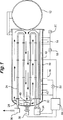
図1に示されるように、従来の典型的なオートクレーブは、長さ約3.7メートル(12フィート)、直径約1.5メートル(5フィート)を有する圧力容器をベースとしており、この容器は、本体10及びローディングドア(loading door)12を有している。真空ライン14が、型押しされるワークピースを有するフレキシブルな隔壁によって覆われた型押しツール(不図示)の押し型側に結合するために設けられており、上記型押しされるワークピースは上記ツールと上記隔壁の間に位置している。上記ツールは、バルブ18を介して真空に接続可能であり、また、バルブ20を介して空気に接続可能である。バルブ22は、空気を圧力ライン16を介して圧力容器の内部へ入れるために操作可能である。加熱は、圧力容器の長さに沿って上下に走る、露出された放射チューブ24によってなされる。各チューブへの入口にはガス燃焼ヒータ34が設けられ、各チューブの放出口にはインペラー(impeller)36が設けられており、このインペラーにより、負圧が放出端へ向けて生成されて、煙道ガス(flue gas)の流れがチューブを介して維持される。タンクの端壁に取り付けられたモータ38が半径流インペラー40を駆動して、圧力容器内に気体の再循環流を生成する。タンク壁10を通過した、気体温度に応答する熱電対42が、制御ユニット44に接続されており、この制御ユニットが各種ヒータに動作的に接続されることで、これらヒータをオン・オフさせ、オートクレーブ内の気体雰囲気を目標値の±1°以内に維持する。各種速度のインペラーを使用することで、同一のチューブを加熱用に使用したり、動作サイクルの冷却工程中に室温に戻すのに使用したりすることを可能にすることが、EP-A-0333389に開示されている。他の設計によるオートクレーブは、電気加熱、蒸気加熱、オイル加熱、高温空気加熱、又はガス放射加熱であってもよいが、今日まで、それらは端壁のインペラーに依存することで、図1中に矢印で示されるような再循環気体の一般に軸方向の単一パターンを生成させるものであった。
As shown in FIG. 1, a typical conventional autoclave is based on a pressure vessel having a length of about 3.7 meters (12 feet) and a diameter of about 1.5 meters (5 feet). A
CH-A-227794(Schweizerische Lokomotiv- & Maschinenfabrik)には、ロードの高温空気処理又は飽和蒸気処理のためのオートクレーブが開示されており、このロードは図示の実施形態では明らかに鉄道貨物貨車で運搬されるものである。このオートクレーブは、ロード空間に沿って配置された複数のインペラーを備えており、そのそれぞれが、ロード空間の周囲であってロード空間を横切るように加熱気体の一般にバイローバル(bilobal;2つのローブ)の環状循環を生成している。 CH-A-227794 (Schweizerische Lokomotiv- & Maschinenfabrik) discloses an autoclave for high-temperature air treatment or saturated steam treatment of roads, which is clearly carried by rail freight wagons in the illustrated embodiment. Is. The autoclave is equipped with a plurality of impellers arranged along the load space, each of which is generally a bilobal of heated gas around the load space and across the load space. Annular circulation is generated.
US6240333(Lockheed-Martin)は、オートクレーブにおける複合材部品の製造に関するものである。Lockheed-Martin が説明するところによると、F22 Raptorは、プライ(ply)と呼ばれるフレキシブルな黒鉛繊維で形成された複合材料でその多くができた航空機の一例であり、上記プライは、加熱すると硬化するエポキシ樹脂又はBMI樹脂が含浸されている。硬化していないプライがツール上に配置され、各ツールが Raptor の複合材部分に相当している。従って、黒鉛樹脂混合物がツール上を覆って硬化すると、複合材部分が正しい形状に成形される。Lockheed-Martin が説明を続けるところによると、複合材部品を成形するのに多くの製造技術を利用可能である。再度、Raptorを例として用いれば、プライが一度ツールを覆って配置されると、樹脂の硬化中にプライをツールに固定しておくのに真空バッグ(vacuum bag)が使用される。この真空バッグは、材料をツールに強く押しつけて、気泡やその他の欠陥が形成されるのを防止する。その後、ツールはオートクレーブ内に配置されることで、計画に従って加熱され、付着される。これは、欠陥部品の生成を避けるために必須であるかもしれない。 US6240333 (Lockheed-Martin) relates to the production of composite parts in autoclaves. Lockheed-Martin explains that the F22 Raptor is an example of an aircraft made up of a composite material made of flexible graphite fibers called ply, which is cured when heated. Impregnated with epoxy resin or BMI resin. An uncured ply is placed on the tool and each tool corresponds to a composite part of the Raptor. Accordingly, when the graphite resin mixture is cured on the tool, the composite material portion is formed into a correct shape. As Lockheed-Martin continues, many manufacturing techniques are available to form composite parts. Again, using Raptor as an example, once the ply is placed over the tool, a vacuum bag is used to secure the ply to the tool during resin curing. The vacuum bag presses the material strongly against the tool to prevent bubbles and other defects from forming. The tool is then placed in an autoclave and heated and deposited according to the plan. This may be essential to avoid the creation of defective parts.
Lockheed-Martin は、更に次のように説明する。オートクレーブの操作者は、オートクレーブの加熱室内にツールを注意深く配置して、加熱速度の規格を確実に満足するようにしなければならない。ここで、典型的なオートクレーブは長さが15メートル(50フィート)であるが、それでもまだ、加熱室の一端に配置された大型ファンで空気を吹きつけることにより加熱される。この加熱方法によって製造プロセス中に導かれる多くの困難性が確認されており、とりわけ、オートクレーブの操作者が加熱速度をより低いレベルに調整することで一部分の過熱を避けようとした場合に、オートクレーブが他部分を硬化するのにより多くの時間が必要となり、製造工程全体に要求される時間が増加するという問題や、部品が不正確に配置された場合に、オートクレーブの操作者が幾つかのツールにおける加熱速度の規格を破ることで、それらのツールの部品を無駄にして、他のツールの有用な部品を得る必要があるかもしれないという問題が確認されている。Lockheed-Martin によって提案された解決策は、オートクレーブ内に導入されるべきロード(load)内にワークピースを適切に配置するためのロード配置ソフトウェア(load distribution software)を設けることである。このソフトウェアは、(a)選択された特定のツール、(b)該ツールの熱性能(thermal performance)、及び(c)オートクレーブの熱特性(thermal characteristics)に依存しつつ、オートクレーブの加熱容器内に、選択されたツールの最良のレイアウトを決定するレイアウトエンジンを含んでおり、このレイアウトエンジンはグラフィカルユーザインタフェース上に結果としてのパターンを生成する。このレイアウトパターンは、以下のものに依存して決定される。 Lockheed-Martin further explains: The autoclave operator must carefully place the tool in the autoclave heating chamber to ensure that heating rate specifications are met. Here, a typical autoclave is 15 meters (50 feet) in length, but is still heated by blowing air with a large fan located at one end of the heating chamber. Many difficulties have been identified during the manufacturing process with this heating method, especially when the autoclave operator attempts to avoid partial overheating by adjusting the heating rate to a lower level. Requires more time to cure other parts, increasing the time required for the entire manufacturing process, and if the parts are placed incorrectly, the autoclave operator Breaking the heating rate standard in the US has been identified as a problem where parts of those tools may be wasted and useful parts of other tools may need to be obtained. The solution proposed by Lockheed-Martin is to provide load distribution software to properly place the workpiece within the load to be introduced into the autoclave. The software is dependent on (a) the particular tool selected, (b) the thermal performance of the tool, and (c) the autoclave's thermal characteristics, while in the autoclave heating vessel. A layout engine that determines the best layout of the selected tool, which generates the resulting pattern on a graphical user interface. This layout pattern is determined depending on the following.
・データベースに格納された、ツールの熱応答。
・オートクレーブの加熱における半径方向及び軸方向の相違であって、高加熱の領域内に配置された低速応答ツールと、低加熱の領域内に配置された高速応答ツール。
Tool thermal response stored in a database.
A difference between the radial direction and the axial direction in the heating of the autoclave, which is a low-speed response tool arranged in the high heating area and a high-speed response tool arranged in the low heating area.
・ロード周辺の均一な空気流。
・指示されたパターンでローディングすることの実行可能性。
しかし、Lockheed-Martin は、どのようにしてレイアウトエンジンを作成すべきなのか、どのような計算をレイアウトエンジンが実行すべきなのか(特に空気流の均一性に関して)について、何ら詳細な説明を行っていない。
・ Uniform air flow around the road.
• The feasibility of loading with the indicated pattern.
But Lockheed-Martin gives a detailed explanation of how the layout engine should be created and what calculations the layout engine should perform (especially with regard to airflow uniformity). Not.
本発明は、質量、形状、及びその長さに沿った断面が異なるロードを扱う立場となるためには、かつ、ロード全体が意図した熱処理を受けうる機会を改善するためには、オートクレーブがたまたま有するどんな特性をも受け入れるためというよりはむしろロードの特性を考慮するためにオートクレーブの特性を変更したり、ロードの特性を変更したりすることが、本質的に一層良い、という前提に基づいている。 The present invention happens to autoclave in order to be able to handle loads with different masses, shapes, and cross-sections along their lengths, and to improve the chances that the entire load can undergo the intended heat treatment. It is based on the premise that it is inherently better to change the characteristics of the autoclave or change the characteristics of the load to take into account the characteristics of the road rather than accepting any characteristics it has. .
長く延びた形状のパネルを含む複雑なロードがオートクレーブ内で熱処理される時に生じる1つの問題は、オートクレーブに沿った異なる位置では、ロードの相対位置や断面にも相違があるかもしれず、この相違が、軸方向への気体循環を有するオートクレーブにおいては循環気体の速度を変化させ、よってロードへの伝熱速度を変化させてしまう、ということである。 One problem that arises when complex loads containing elongated shaped panels are heat treated in an autoclave is that at different locations along the autoclave, there may be differences in the relative position and cross-section of the load. In an autoclave having a gas circulation in the axial direction, the speed of the circulating gas is changed, and thus the heat transfer speed to the load is changed.
その問題は、オートクレーブ内で前述のようにロードを熱処理する方法によって解決される。この方法は、ロード空間内の加熱された気体を、その長さに沿って配置された複数の気体循環手段によって循環させることと、その各々が上記の加熱された気体を、ロード空間の一般に非軸方向に循環させ、及び/又は、ロード上に非軸方向にぶつけることとを含んでいる。 The problem is solved by the method of heat treating the load in the autoclave as described above. In this method, the heated gas in the load space is circulated by a plurality of gas circulation means arranged along its length, and each of the heated gases is generally non-exposed in the load space. Circulating axially and / or bumping non-axially on the load.
複雑なロードがオートクレーブ内で熱処理される時に生じる他の問題は、オートクレーブに沿った異なる位置でロードの熱特性に相違が存在するということであり、この問題は、軸方向の気体循環を有するオートクレーブでは、位置毎の伝熱速度における既知又は予測される相違を考慮してロードの配置を調整することのみによって解消することは困難であるかもしれない。 Another problem that arises when complex loads are heat treated in an autoclave is that there are differences in the thermal properties of the load at different locations along the autoclave, which is an autoclave with axial gas circulation. Thus, it may be difficult to resolve by only adjusting the load arrangement to take into account the known or predicted differences in heat transfer rates from position to position.
その問題は、本発明によれば、熱特性がロードに沿った位置で変化するようなロードを熱処理する方法によって解決される。この方法は、その長さに沿って配置された複数の気体循環手段を有するオートクレーブ内でロードを加熱することと、そのそれぞれが加熱気体の循環のための区域を生成することとを備え、上記区域内での気体循環が独立して制御可能である。この方法では、様々な形状及び質量のロードが、その長さに沿って異なる温度で、又は気体循環の異なる速度で加熱されることを可能とすることで、その質量全体の温度を均一な速度で上昇させるようにしている。 The problem is solved according to the invention by a method of heat treating a load whose thermal properties change at a position along the load. The method comprises heating a load in an autoclave having a plurality of gas circulation means disposed along its length, each creating an area for circulation of the heated gas, The gas circulation in the area can be controlled independently. This method allows the load of various shapes and masses to be heated at different temperatures along their length, or at different rates of gas circulation, thereby making the temperature of the entire mass uniform. I try to raise it.
従って、本発明は、長く延びた形状のパネルを成形する方法を提供するものであって、この方法は、
前記パネルをその成形用の成形ツールに接触させることによってロードを生成することと、
体積が250立方メートルよりも大きく、ロード空間のアスペクト比が3よりも大きなオートクレーブ内で前記ロードを熱処理することとを備えており、
前記製品の最長寸法が前記オートクレーブの軸に対して一般に平行に向いており、前記パネル及び前記成形ツールが前記オートクレーブの内部空間のより大きい部分に沿って延びており、前記ロードの熱特性が前記ロードに沿った位置で変化し、前記オートクレーブはその長さに沿って配置された複数の気体循環手段を有し、該気体循環手段のそれぞれが、前記ロード上に非軸方向にぶつかるようになされ、かつ、前記ロードをその長さに沿って異なる温度で、及び/又は気体循環の異なる速度で加熱するようになされる加熱気体循環のための区域を生成することにより、前記ロード全体の温度が均一の速度で上昇するようにした方法である。
Accordingly, the present invention provides a method of forming a panel having a long and elongated shape,
Generating a load by contacting the panel with a molding tool for the molding;
Heat treating the load in an autoclave having a volume greater than 250 cubic meters and an aspect ratio of the load space greater than 3.
The longest dimension of the product is oriented generally parallel to the axis of the autoclave, the panel and the molding tool extend along a larger portion of the interior space of the autoclave, and the thermal characteristics of the load are The autoclave has a plurality of gas circulation means disposed along its length, each of the gas circulation means being adapted to collide non-axially on the load. And by creating zones for heated gas circulation that are adapted to heat the load at different temperatures along its length and / or at different rates of gas circulation, the temperature of the entire load is reduced. In this method, the ascending speed is uniform.
<好ましい構成についての記載>
上記のオートクレーブは、その長さ方向に一連の処理区域に分割され、好ましくは、各区域内における加熱気体とロードとの間の伝熱速度を制御するための手段がインペラーを備えている。このインペラーは二重の機能を提供可能であるということがわかっている。すなわち、第1には、循環気体の速度を調整することで、ロードへの伝熱係数を調整する機能であり、第2には、所望の速度又は質量流で、特に、オートクレーブ内で見いだされる典型的な使用圧力5−25bar で気体循環を生成するのに実際に要求されるハイパワー入力の故に、加熱気体のための熱源として作用する機能であり、好ましくは、各処理区域のインペラーによって加熱気体中に生成された摩擦熱を独立に調整するための手段が設けられる。オートクレーブ内に気体温度及びロード温度を測定する1つ以上の熱電対を設け、測定温度と必要温度との差を用いてインペラー速度を調整するための差信号を生成することで、インペラーの生成する摩擦熱量が細かな温度制御を提供し、オートクレーブのプロセスサイクルのロード加熱期間中にロード温度±1oCの達成を可能にできる、ということが実際にわかっている。各区域内での加熱気体とロードとの間の伝熱速度を制御するための手段は、好ましくは、当該区域内を循環する気体を冷却するための冷却手段も備えている。オートクレーブの長さに沿った区域での、及び任意ではあるが単一の区域内の異なる領域での気体流の速度を調整できるということは、処理サイクルの冷却期間中に、ロードに沿った異なる領域の周辺における気体流経路の相違を参酌する上で、また、ロードに沿った異なる領域でのツール及びワークピースの熱容量の相違を参酌する上でも、特別な価値がある。区域毎又は区域群内の主な熱、各区域内の質量流速、各区域内での摩擦熱の発生、各区域内の冷却を、独立して調整するよう準備することは、高度の安定性を達成できるようにする。
<Description of preferred configuration>
The autoclave is divided into a series of treatment zones along its length, preferably means for controlling the heat transfer rate between the heated gas and the load in each zone is equipped with an impeller. It has been found that this impeller can provide a dual function. That is, the first is the function of adjusting the heat transfer coefficient to the load by adjusting the speed of the circulating gas, and the second is the desired speed or mass flow, especially found in the autoclave. The function of acting as a heat source for the heated gas because of the high power input that is actually required to produce a gas circulation at a typical working pressure of 5-25 bar, preferably heated by an impeller in each processing zone Means are provided for independently adjusting the frictional heat generated in the gas. One or more thermocouples for measuring the gas temperature and load temperature are provided in the autoclave, and the difference signal for adjusting the impeller speed is generated using the difference between the measured temperature and the required temperature, thereby generating the impeller. It has actually been found that the frictional heat provides fine temperature control and can achieve a load temperature of ± 1 ° C. during the load heating period of the autoclave process cycle. The means for controlling the heat transfer rate between the heated gas and the load in each zone preferably also comprises a cooling means for cooling the gas circulating in the zone. The ability to adjust the rate of gas flow in zones along the length of the autoclave, and optionally in different regions within a single zone, varies along the load during the cooling period of the processing cycle. There is particular value in considering differences in gas flow paths around the region and also in consideration of differences in heat capacity of tools and workpieces in different regions along the load. Preparing to independently adjust the main heat in each zone or group of zones, the mass flow rate in each zone, the generation of frictional heat in each zone, and the cooling in each zone is highly stable. To achieve.
循環気体を加熱することに関して、電気は1つの可能な熱源であり、この場合、各区域内を循環する気体を加熱するための独立したヒータを設けるのが便利である。例えば放射チューブを使用する、ガス、蒸気、又はオイル加熱の場合は、加熱手段が、区域群に共通の少なくとも第1のヒータを備えていてもよく、典型的には、第1及び第2の区域群のための少なくとも第1及び第2のヒータを備えていてもよい。制御手段は、時間で変化するパターンにおいて少なくとも1つの区域に異なる状態を生成するようにしてもよい。 With respect to heating the circulating gas, electricity is one possible heat source, in which case it is convenient to provide an independent heater for heating the gas circulating in each zone. In the case of gas, steam or oil heating, for example using radiant tubes, the heating means may comprise at least a first heater common to the group of zones, typically the first and second There may be at least first and second heaters for the group of zones. The control means may generate different states in at least one area in a time varying pattern.
気体循環のパターンは非軸方向であり、一般に1よりも大きなアスペクト比を有するロード空間の軸又は縦方向を横切る方向である。好ましくは、各区域内に、気体の周辺バイローバル(bilobal;2つのローブの)循環を生じさせるための手段が設けられており、この周辺バイローバル循環の面が上記の縦方向又は軸に対して一般に直角となっている。そのような循環パターンを達成するために、オートクレーブは、互いに対面配置され、その部屋の周辺に沿った気体の流れのための部屋空間の側壁を規定する内壁部分と、上記流れ空間への気体の導入のための、上記内壁部分間に規定される第1の開口と、上記流れ空間を出て上記部屋を介して上記第1の開口に向かって流れる気体のための、上記第1の開口とは対向する内壁部分間に規定される第2の開口とを更に備えていてもよい。ロード上を移動する加熱気体の質量流を増加させて、伝熱係数を増加させるために、ロード上方の気体の体積を減少させて気体の速度を上昇させるための手段を設けることが好ましい。そのためには、オートクレーブ内に、ロード近くの気体の速度を変化させるための少なくとも1つの気体偏向手段を設けるのが好ましく、また、部屋の外部から上記気体偏向手段の位置を調整するためのアクチュエータ手段を上記気体偏向手段に結合するのが好ましい。 The pattern of gas circulation is non-axial, generally across the axis or longitudinal direction of the load space having an aspect ratio greater than 1. Preferably, means are provided within each zone for creating a peripheral bilobal circulation of gas, the surface of the peripheral bilobal circulation generally being in relation to the longitudinal direction or axis described above. It is a right angle. In order to achieve such a circulation pattern, the autoclaves are facing each other and an inner wall portion defining the side wall of the room space for the flow of gas along the periphery of the room, and the flow of gas into the flow space. A first opening defined between the inner wall portions for introduction, and the first opening for a gas flowing out of the flow space toward the first opening through the chamber May further comprise a second opening defined between opposing inner wall portions. In order to increase the heat transfer coefficient by increasing the mass flow of the heated gas moving on the load, it is preferable to provide means for increasing the gas velocity by decreasing the volume of the gas above the load. For this purpose, it is preferable to provide at least one gas deflection means for changing the velocity of the gas near the load in the autoclave, and an actuator means for adjusting the position of the gas deflection means from the outside of the room. Is preferably coupled to the gas deflection means.
上記のオートクレーブは、最長寸法方向がオートクレーブの軸に対して一般に平行に向いている長く延びた製品を熱処理するのに使用可能であり、その熱処理は、所定パターンに従って上記製品を加熱するように実行され、通常は製品の長さに沿って温度が均一に上昇するようになされる。上記製品は、縦方向と横方向の両方の湾曲を有する航空機翼のためのパネルであってもよい。 The above autoclave can be used to heat an elongated product whose longest dimension is generally parallel to the axis of the autoclave, and the heat treatment is performed to heat the product according to a predetermined pattern. Usually, the temperature rises uniformly along the length of the product. The product may be a panel for an aircraft wing having both longitudinal and transverse curvature.
一般に、ロードは、それぞれがツールに接触したワークピースからなるパネルを備えており、ワークピースはツールと接触したままで熱処理され成形される。これは、複合材を成形する際、複合材と成形ツールとの間の境界を排気すると共に、オートクレーブ内の高温気体雰囲気に圧力を加えるのと同様である。オートクレーブは、その主な利用の1つとして、オートクレーブの内部空間の主要部分に沿って延びる単一のパネル及び単一の成形ツールの処理を有している。それはまた、オートクレーブの内部空間の主要部分に沿って相並んだ関係にある複数のパネル及び成形ツールの処理にも利用可能である。それはまた、上記内部空間に沿って縦一列に配置された複数のパネル及び成形ツールの処理にも利用可能である。成形部品の製造へのオートクレーブの利用は、硬化可能なプラスチック又は複合材料を使ったパネルの製造に限定されるものではなく、形状を変化させたり特性を改善するための熱処理を受ける必要のある金属製のパネルをも含んでいる。 Generally, a load comprises a panel of workpieces each in contact with a tool, and the workpiece is heat treated and molded while in contact with the tool. This is similar to evacuating the boundary between the composite and the forming tool and applying pressure to the hot gas atmosphere in the autoclave when molding the composite. Autoclaves, as one of their main uses, have the treatment of a single panel and a single molding tool that extend along the main part of the interior space of the autoclave. It can also be used to process multiple panels and forming tools in a side-by-side relationship along a major portion of the interior space of the autoclave. It can also be used to process a plurality of panels and forming tools arranged in a vertical row along the internal space. The use of autoclaves in the production of molded parts is not limited to the production of panels using curable plastics or composites, but metals that need to undergo heat treatment to change shape or improve properties Includes panels made of steel.
エージクリープ成形(age creep forming)は、金属プレートを所望の輪郭形状に成形するのに利用可能であり、例えばアルミニウム又は合金の翼パネルに翼形状を与えるのに利用可能である。このエージクリープ成形に含まれる実際のステップは、硬化可能な合成物を型成形する際に含まれるステップに非常に類似している。機械加工に続いて、金属パネルが型の上に配置され、高温に耐えるプラスチック材料のシートで覆われる。その組立体が、オートクレーブ内に配置されて、シートの下の空気が排気され、オートクレーブの内部が加圧されることで、パネルが型上に強く押しつけられ、そして、オートクレーブが例えば約220oCに加熱される。或る期間、例えば24時間後、パネルが室温まで冷却され、オートクレーブから取り出される。US-A-4188811(Chem-tronics)は、金属製のワークピースを成形するためのプロセスを開示しており、これは、片面型を使用すると共に、クリープ成形によってワークピースを型表面の形状と同一形状にするのに熱及び圧力を利用するものである。特に、この特許は、金属製のワークピースの形状を変えるためのプロセスを開示しており、これは、ワークピースに要求される形状を有する型面上にワークピースを配置するステップと、上記ワークピースを加熱することとそれにコンプライアント体(compliant body)を介して圧力を加えることとを同時に行うステップとを備え、このコンプライアント体は個別の耐熱・圧力伝達材料から構成されて、ワークピースにおける型とは反対の側に配置されており、ワークピースが加熱される温度と印加される圧力とが互いに関連づけられることで、ワークピース金属がその降伏強さよりも小さな応力でプラスチックのように流れて型面と接触し、その結果、所望の形状がワークピースに押しつけられる。クリープ成形についてのもっと最近の参照事項は、US-A-5345799(Aliteco AG)及び US-A-6264771(Bornschlegel)に見られる。 Age creep forming can be used to shape a metal plate to a desired contour shape, for example, to impart a wing shape to an aluminum or alloy wing panel. The actual steps involved in this age creep molding are very similar to the steps involved in molding a curable composition. Following machining, a metal panel is placed over the mold and covered with a sheet of plastic material that is resistant to high temperatures. The assembly is placed in an autoclave, the air under the seat is evacuated, the inside of the autoclave is pressurized, and the panel is strongly pressed onto the mold, and the autoclave is, for example, about 220 ° C. To be heated. After a period of time, for example 24 hours, the panel is cooled to room temperature and removed from the autoclave. US-A-4188811 (Chem-tronics) discloses a process for forming a metal workpiece, which uses a single-sided mold and creeps the workpiece into the shape of the mold surface. Heat and pressure are used to make the same shape. In particular, this patent discloses a process for changing the shape of a metal workpiece, which includes placing the workpiece on a mold surface having the shape required for the workpiece; Heating the piece and simultaneously applying pressure to it through a compliant body, the compliant body being composed of individual heat and pressure transmitting materials, Located on the opposite side of the mold, the temperature at which the workpiece is heated and the applied pressure are correlated to allow the workpiece metal to flow like plastic with a stress less than its yield strength. In contact with the mold surface, the desired shape is pressed against the workpiece. More recent references for creep molding can be found in US-A-5345799 (Aliteco AG) and US-A-6264771 (Bornschlegel).
前述したように、オートクレーブの区域内における1つの好ましい気体循環パターンはバイローバル循環であり、これは各区域内でのバイローバル循環の面がオートクレーブの軸を横切る方向に向いており、この場合、バイローバル循環の中央領域での気体がツール上にぶつかり、及び/又はツールを通過する。ツールは、気体循環経路の周辺部分に沿って移動する気体が当該気体がロード空間を横断する気体循環経路の中央部分に入る位置に面した、気体受け入れ開口を有しているのが都合が良い。第2の好ましい気体循環はテトラローバル(tetra-lobal;4つのローブの)循環であり、これは、オートクレーブを断面で見た場合に0°と180°の位置に第1及び第2のインペラーが配置され、内部ロード空間を規定する壁内の裂け目によって90°及び270°の位置に放出出口が規定されており、その結果、内部へ向かう加熱空気の第1及び第2の流れが互いに反対方向からワークピース上にぶつかることを可能にしている。 As mentioned above, one preferred gas circulation pattern within the autoclave zones is bi-lobal circulation, where the plane of bi-circulation circulation within each zone is oriented across the axis of the autoclave, in this case bi-lobal circulation. The gas in the central region of the gas hits the tool and / or passes through the tool. The tool advantageously has a gas receiving opening facing the position where the gas moving along the peripheral part of the gas circulation path enters the central part of the gas circulation path where the gas traverses the load space. . The second preferred gas circulation is a tetra-lobal circulation, where the first and second impellers are at 0 ° and 180 ° positions when the autoclave is viewed in cross section. The discharge outlets are defined at 90 ° and 270 ° positions by a tear in the wall that is arranged and defines an internal load space, so that the first and second flows of heated air towards the interior are in opposite directions Makes it possible to bump onto the workpiece.
本発明がどのように作用するかについて、添付図面を参照しつつ、その一例のみを用いて説明する。 The operation of the present invention will be described using only an example thereof with reference to the accompanying drawings.
本発明は、特には、アスペクト比の大きなオートクレーブ、体積の大きなオートクレーブ、又は体積が大きくかつアスペクト比も大きなオートクレーブに適用可能であるが、これに限定されるわけではない。オートクレーブは長さ15メートルであってもよく、また、典型的な設備では、長さ約35メートルのものもあり、その長さには、選択された非軸方向の流れパターンの故に、特定の上限は存在しない。オートクレーブの体積は、250立方メートルよりも大きく、しばしば500立方メートルを超えており、典型的な設備では750立方メートルを超えている。オートクレーブ内のロード空間のアスペクト比(直径又は最大横寸法に対する長さの比)は、3より大きく、通常は5よりも大きく、典型的な設備では約7である。 The present invention is particularly applicable to an autoclave having a large aspect ratio, an autoclave having a large volume, or an autoclave having a large volume and a large aspect ratio, but is not limited thereto. Autoclaves may be 15 meters long, and typical installations may be about 35 meters long, which may have a specific length due to the selected non-axial flow pattern. There is no upper limit. The volume of the autoclave is greater than 250 cubic meters, often exceeding 500 cubic meters, and in typical installations exceeding 750 cubic meters. The aspect ratio of the load space in the autoclave (diameter or ratio of length to maximum lateral dimension) is greater than 3, usually greater than 5 and about 7 in typical installations.
大きな航空機翼用のパネルであって、翼が航空機の胴体に結合されている場所から生じているパネルのような部品が、ファン52による軸方向の空気循環を有する従来のオートクレーブ50内で熱処理される場合に生じる問題が、図2に示されている。翼パネル54は、例えば、アルミニウム合金であって、断面が一般に付け根の方では40mm、先端の方では4mmで、横と縦の両方向に湾曲しており、その長さに沿って断面が全般的に徐々に変化している。一般に厚さ約10mmの鋼板からなるツールが、クリープ成形されるパネル54を支持し、このパネルすなわちワークピースが、ツールに沿って又はツールを横切って配置されたねじジャッキによって規定される基準面上に引き下ろされる。パネルは、ゴムシートによって覆われ、真空又はオートクレーブ内の気体圧によって基準面上に引き下ろされる。この場合のオートクレーブは、一般に20barまでの圧力で、200oCまでである。
A panel for a large aircraft wing, such as the panel originating from where the wing is joined to the aircraft fuselage, is heat treated in a
クリープ成形のためには、パネル54の受けるべき熱レジーム(thermal regime)のための典型的な仕様は、パネルが目標温度の±2oCに加熱されなければならないということ、及び、パネルの最も厚い部分が最も薄い部分の1時間以内にその目標温度に達しなければならないということである。熱がパネルに到達するのは、主に、ゴムカバーシート上に加熱気体がぶつかることによってであり、そのために、空気に対流を生じさせ、ゴムカバーシートに熱伝導を生じさせ、アルミニウムパネルに熱容量を持たせることが必要である。
For creep molding, the typical specification for the thermal regime to be experienced by the
図2においては、明瞭になるようツールは省略してある。明らかなように、気体は、矢印60で示されるようにオートクレーブの側壁56と内壁58との間をファン52から軸方向に流れ、そして内部へ向かって折り返すことで軸方向の戻り流61を提供する。放射チューブ加熱要素(不図示)が壁56、58間に設けられている。オートクレーブは3つのセグメントに形成されており、すなわち、ファンから最も遠いセグメント62、中央のセグメント64、及びファンに最も近いセグメント66を備えている。ファン52から最も遠いセグメント62内では、パネル54は内壁58から比較的広い間隔にあり、気体流は比較的ゆっくりしている。中間のセグメント64内では、パネル54と内壁58との隙間が狭く、気体流はそれに応じて増加した伝熱係数で加速される。ファン52に最も近いセグメン66内では、パネル54の逆方向への湾曲のために、加熱気体はもはやゴム被覆層上に直接ぶつかることがなく、その代わりに、加熱気体の一部がそこをバイパスして矢印68で示されるようにファンへ直接に戻り、その残りは矢印70で示されるように乱流となる。このように異なる気体流レジームと、それによって生じるロード(ワークピース及び/又はツール)伝熱係数の相違とによって生じる問題を解消するためには、ファン52は、流路の長さに起因する高い定常水頭に対抗し、かつ、流路の流出部分内のヒータや流路の戻り部分内のロードによって提供される障害物に対抗する、非常に高い気体流を生成しなければならない。主な気体流は図示のようにパネル54の表面上にあるので、ツールを通る気体流はプロセスには大きく寄与しない。必然的に、ロードの一端は他端よりも温度が低い。メガワット(MW)のファン電力が必要とされ、これは非常に大きなコストを伴うものであり、不等率がゼロである。
In FIG. 2, tools are omitted for clarity. As can be seen, the gas flows axially from the
本発明は、これらの問題を解消するものであり、それは、図3に示すように、加熱気体の一般に非軸方向の流れパターンを提供することによる。この流れパターンは、放射チューブを通り過ぎた流れによって加熱可能な場所であるオートクレーブの内壁と外壁間を周辺方向に循環し、ロード空間を横切る気体を伴うものであって、これにより、矢印72で示されるように流れがロード上にぶつかるようになる。オートクレーブの軸に対して一般に直角を向いている平面内における気体循環のパターンは、ロード空間を、不等率を有するロードの温度が均一に維持されるよう気体流(の速度及び温度)が独立して制御可能である多数のプロセス区域(processing zones)に分割する機会を提供する。本発明の実施形態では、各セグメント毎の周辺方向への流れが、オートクレーブの最上位領域に取り付けられ当該最上位領域に沿って軸方向に配置された冷却ユニットを通過してから、その下方へ案内される。この冷却ユニットは、第1に、処理サイクルの加熱期間中に循環気体の温度を調整して、オートクレーブにおけるほとんどロードのない又は全くロードのない領域を過加熱するのを防止するのに役立ち、また第2に、処理サイクルの冷却期間中に温度を周囲温度に戻すのを手助けするのに役立つ。冷却ユニット74、76、78がセグメント62内に設けられ、冷却ユニット80、82、84がセグメント64内に設けられ、冷却ユニット88、90、92がセグメント66内に設けられている。周辺方向の流れは、冷却ユニットに入り、それから図示のようにロードへ向かって下方へ案内される。気体の移動における戻り部分では、オートクレーブの床下にある整合ユニット内のインペラーが、気体をロード空間から壁56、58間へと戻してやることで周辺方向の流れを生じさせている。
The present invention overcomes these problems by providing a generally non-axial flow pattern of the heated gas, as shown in FIG. This flow pattern involves a gas that circulates in the peripheral direction between the inner and outer walls of the autoclave, where it can be heated by the flow past the radiant tube, across the load space, and is indicated by
ロードを配分することに加え、オートクレーブに沿って所々に配置された多数のインペラーを用いることで、各インペラー毎の定常水頭が低下し、その結果、オートクレーブの空気移動の必要性を大幅に譲歩することなしに、もっと小型のモータを利用することが可能になる。より小型のモータは製造及び取り付けが容易であり、制御の改善を提供するものであるが、その理由は、まず、各モータによって制御された横方向の流路が従来のオートクレーブにおける軸方向の流路と比べて比較的短いからであり、また、インペラー速度の調整が、質量流を制御するためだけでなく、特に比較的に高いオートクレーブ内圧で熱入力の重要な均衡を提供しうる、各インペラーで与えられる摩擦熱の量を制御するためにも利用可能だからである。モータは、気体循環に必要とされるよりも大きな定格パワー出力を有しているのが好ましく、そのようにすることで、余分なパワーを区域内での気体の摩擦加熱に利用可能である。もし、オートクレーブに沿って所々に配置された複数のモータ及びインペラーによってデューティが配分され、従来技術のオートクレーブのように端壁内の単一モータによってデューティが配分されるのでなければ、プロセスサイクルの休止期間において重要である摩擦加熱の利用は容易である。 In addition to distributing the load, the use of multiple impellers located along the autoclave reduces the steady head of each impeller, resulting in a significant concession to the need for air movement in the autoclave. Without this, it becomes possible to use a smaller motor. Smaller motors are easier to manufacture and install and provide improved control because the lateral flow path controlled by each motor is first the axial flow in a conventional autoclave. Each impeller because the adjustment of the impeller speed can provide an important balance of heat input, not only for controlling the mass flow, but especially at relatively high autoclave internal pressures. This is because it can also be used to control the amount of frictional heat given by. The motor preferably has a higher rated power output than is required for gas circulation, so that excess power is available for frictional heating of the gas in the area. If the duty is distributed by a plurality of motors and impellers located at various locations along the autoclave, and the duty is not distributed by a single motor in the end wall as in the prior art autoclave, the process cycle pauses The use of friction heating, which is important in the period, is easy.
図3のオートクレーブの断面が図4a−4hに示されており、これらの図では、オートクレーブが側壁56とそれに対面する弧状の側壁58、58aとを有しており、この側壁58、58aは側壁56と共に、ガス燃焼型の放射ヒータチューブ96を含む周辺気体循環空間95を規定している。図4aから明らかなように、各セグメントは、片側毎に6個のガスバーナによって燃焼される6個の放射チューブを有しており、各セグメン毎に12個の放射チューブ及びガスバーナが与えられている。ガス燃焼型の放射チューブはほんの一例であり、他の加熱形態を採用してもよいということがわかる。ロード空間98は、内壁58、58a、天井100、床102、冷却ユニット(この場合は天井取り付けのユニット76)、及び床取り付けのインペラー104の間に規定されている。ロード106はロード空間内に存在し、成形されるパネル及び成形ツールの形態になっており、この成形ツールは変形可能な材料からなるブランケットか、パネルを覆う剛直な第2ツール部分を有すると共に、パネル下に真空を供給して成形作業を手助けするための手段(不図示)を有している。
Cross sections of the autoclave of FIG. 3 are shown in FIGS. 4a-4h, in which the autoclave has a
連続した図中に矢印で示されるように、ロード106の下側からの加熱気体がインペラーすなわちファン104内に通過し(図4b)、そこから気体循環空間95へと放出されてそこを周辺方向に流れ(図4d、4e)、冷却ユニット76へと到達する。インペラーすなわちファンは、通常は遠心ファンであり、これはケーシングと、(この実施形態では)床内の開口に連結された入口と、オートクレーブの横方向を向いた互いに対面する第1及び第2の出口とを有している。このようにすることで、ロード空間からの気体は、オートクレーブの互いに対向する側にある取り囲まれた空間を介して、それぞれの冷却ユニット例えば76の方へと区域毎に流れる。冷却ユニットを出た気体は、下方へ向けて、ロード106の一部を形成する成形ツールの上又は中へと通過していき、次に成形ツールを通過して(図4f、4g、4h)、ロードの下側へと戻ってくる(図4b)。従って、各区域内において、周辺方向のバイローバル循環が確立される。この循環では、ロードが中央領域すなわちロード空間内にあり、この場所で、2つのローブ(lobes)からの気体流が結合して横方向(この場合は下方向)へと移動し、ツール上にぶつかって局所的に乱れた熱伝導流パターンを生成することが可能である。
As indicated by the arrows in the successive figures, the heated gas from the underside of the
岩綿又はその他の不活性の耐熱絶縁材料からなる内部断熱材59が、オートクレーブの外部シェルの裏地として設けられることで、加熱期間中にオートクレーブのシェルからの伝熱を減少させてシェルへの熱応力を減少させ、なおかつ、処理サイクルの冷却期間中にシェルからロード空間へと戻る伝熱をも減少させている。このようにすることで、各サイクル毎のエネルギー要求は、ロード又はプロセス質量(process mass)を加熱又は冷却するのに必要とされるエネルギー要求に近づき、より小さなエネルギーで、容器やシェル及びそのドアの質量を含むオートクレーブの合計質量を加熱及び冷却することになる。各処理サイクル中にオートクレーブのシェルを加熱又は冷却するエネルギーは、浪費エネルギーであり、最小にすることが望ましい。弧状の側壁58、58a、天井100、及び床102は、連続面を形成することで、インペラー104からの全ての空気流が気体循環空間95を通過して冷却ユニット76へと至り、取りこぼし(overspill)を引き起こし得るようなエアギャップは存在しない。エアギャップが存在しないことは重要なことではなく、例えば、ワークピース及び成形ツールの特定領域上に加熱空気を送るために、側壁58、58aにポート(ports)が形成されていてもよい。しかし、そのようなポートは特定のツール及びワークピースに特有と思われるので、あまり好ましくない。このように、オートクレーブは、各作業目的毎にそれぞれ組み立てられることになる。
An
図3のオートクレーブのレイアウトは、オートクレーブ及びそれに関連する制御システムの概略図である図5に、図式的に示されている。例えばEP-B-0176508及びEP-B-0333389に記載されているように、セグメント62、64、66は、放射チューブ110によって加熱され、ガスバーナ112によって燃焼される。放射チューブは、図5cの一部を構成する図式部分中にG1−G12として表され、軸方向を向いており、その各々が、独立に制御可能な冷却器74、76、78、80、82、84、88、90、92と、独立に制御可能なインペラー114、116、118;120、122、124;126、128、130とによってそれぞれ規定された3つの加熱区域を通過している。各セグメントにおけるガスバーナは熱電対G1−G12と関係している。これら熱電対は、周辺空気の温度を測定し、セグメントヒータロジックユニットICU7、ICU9及びICU11のそれぞれに信号を送る。これらセグメントヒータロジックユニットは、各セグメントに関連する段階的(progressive)ガスバーナコントローラ132、134、136(cold<SP)に命令信号を順番に送る。3つのヒータロジックユニットは、3つのセグメント用のファン・冷却器ロジックユニットICU6、ICU8及びICU10から加熱イネーブル命令138、140、142を受け取る。
The layout of the autoclave of FIG. 3 is shown schematically in FIG. 5, which is a schematic diagram of the autoclave and its associated control system. For example, as described in EP-B-0176508 and EP-B-0333389, the
第1の区域では、熱電対A1及びA2がインペラー114から出てくる流れの温度を測定し、熱電対A3及びA4が冷却器ユニット74に入る流れを測定し、その差が、ロードによって奪われた熱の測定値、又はサイクルの冷却期間中であればロードから放出されたエネルギーの測定値を提供する。バイローバルの流れパターンの故に、熱電対は対になって設けられている。第2の区域では、熱電対A5及びA6がインペラー116から出てくる空気の温度を測定し、熱電対A7及びA8は冷却器ユニット76に入る空気の温度を監視する。第3の区域では、熱電対A9及びA10がインペラー118を出てくる空気の温度を監視し、熱電対A11及びA12が冷却器ユニット78に入る空気の温度を監視する。12個の熱電対からの信号がユニットICU6、ICU8又はICU10に供給される。これらのユニットICUは、ガスバーナ命令信号を提供することに加え、命令信号Z1、Z2、Z3を比例冷却バルブ144、146及び148(Hot<SP)に提供し、かつ、それと同様な信号を各区域のインペラー用の摩擦熱インバータ150、152、154(Hot±SP)に提供する。従って、もしいずれかの区域内の気体が設定点よりも十分に低い場合には、放射チューブ110のガスバーナ112がスイッチオンされる。もしいずれかの区域内の気体の温度が設定点を超えている場合は、冷却が開始され、各区域毎のインバータパワーの調整が気体温度における細かな偏りを補償することが可能になる。
In the first zone, thermocouples A1 and A2 measure the temperature of the
オートクレーブの動作は、加熱系温度及び気体温度の測定に依存するだけでなく、ロード(ツール又はワークピース)の温度にも依存する。そのために、ロードセンサ熱電対1−33及び参照熱電対1−4がセグメント62に割り当てられ、ロードセンサ熱電対34−67及び参照熱電対5−8がセグメント64に割り当てられ、そして、ロードセンサ熱電対68−100及び参照熱電対9−12がセグメント66に割り当てられている。ロジックユニットICU1−ICU4は、それらが監視する熱電対のグループの中の最高温のものと最低温のものを示す信号を温度制御ロジックICU5に供給する。このようにすれば、プロセス質量(ツール+ワークピース)の温度が区域毎に感知され、制御ユニットは、目標温度からのプロセス質量全体の偏りと、個々の区域内での目標温度からの偏りとの両方に応答することが可能である。
The operation of the autoclave not only depends on the measurement of the heating system temperature and gas temperature, but also on the temperature of the load (tool or workpiece). To that end, load sensor thermocouple 1-33 and reference thermocouple 1-4 are assigned to
156(図5c)で示されるように、オートクレーブによって実行されるプロセスサイクルは、装置156に格納されており、通常、オートクレーブの加圧、圧力の休止、及び処理サイクルの冷却期間終了時の圧力の開放を与える、比較的単純な圧力サイクル158を含んでいる。圧力サイクルと同時に起こるワークピースプロセスサイクル160は、所定の温度上昇速度、目標のプロセス温度での休止時間、周囲温度への所定の温度戻り速度を有している。プロセス気体温度サイクル162は、通常はもっと複雑であり、サイクルの加熱期間中にワークピース温度を導く気体温度と、伝熱係数を決定する要因である温度間比とを有している。装置156から、情報が3つのセグメントにおける圧力コントローラ164に供給され、温度設定点が空気/ロード温度比コントローラ166、168、170に供給される。
As shown at 156 (FIG. 5c), the process cycle carried out by the autoclave is stored in the
もしいずれかのワークピース熱電対又は制御熱電対が低すぎる温度を示した場合は、ロジックICU5(図5c)はその情報を休止/低温/高温ロジック165に供給する。このロジックには、温度設定点も供給され、信号を装置156に戻すことで、例えば空気温度設定点を変化させてもよい。装置ICU5は、広がり(spread)制御にも関係している。もしグループ内の熱電対の1つが目標温度又はその近くであって、その他の熱電対が低すぎる温度にある場合、上記ロジックは、低温領域の温度が追いつくまで、それ以上の熱の供給を低減させる(保持する)。もしいずれかのセグメントにおける熱電対が高温になった場合は、信号が比コントローラ166、168又は170に送られることで、問題の熱電対のあるセグメント内の加熱を減少させるようにする。その信号は、セグメントヒータロジックユニットICU7、9又は11と、隣接するセグメントにおけるファン・冷却器ロジックユニットとの両方に送られる。従って、もし熱電対1−33のうちの1つか、参照熱電対1−4のうちの1つがHOT信号を与えた場合は、信号がセグメント62用の比コントローラ166に送られることで、ガスバーナの熱及び/又はインペラーの摩擦熱が減少させられ、また、信号が隣接セグメント64用のファン・冷却器ロジックICU8のパルス速度入力に送られることで、そのセグメント内のいずれか又は全ての区域で生じる摩擦熱が調整される。同様に、もし熱電対34−67のうちの1つか、参照熱電対5−8のうちの1つがHOT信号を与えた場合は、信号がセグメント64用の比コントローラ168に送られることで、ガスバーナの熱及び/又はインペラーの摩擦熱が減少させられ、また、信号が隣接セグメント62及び66用のファン・冷却器ロジックユニットICU6及びICU10のパルス速度入力に送られることで、それらセグメント内のいずれか又は全ての区域で生じる摩擦熱が調整される。更に、もし熱電対68−100のうちの1つか、参照熱電対9−12のうちの1つがHOT信号を与えた場合は、信号がセグメント66用の比コントローラ170に送られることで、ガスバーナの熱及び/又はインペラーの摩擦熱が減少させられ、また、信号が隣接セグメント64用のファン・冷却器ロジックICU8のパルス速度入力に送られることで、そのセグメント内のいずれか又は全ての区域で生じる摩擦熱が調整される。従って、制御回路は、気体温度、ツール温度又はワークピース温度の多数の小さな又は大きな偏りに対しては比較的粗い応答をセグメント毎に実行可能にし、また、目標とする熱処理サイクルからのもっと小さな温度変動に対しては区域毎の冷却、インペラー速度を変化させることによる質量流速の区域毎の調整、及び摩擦熱発生の区域毎の変化を利用することで、もっと細かに調整された区域毎の応答を可能にする。
If any workpiece thermocouple or control thermocouple indicates a temperature that is too low, logic ICU 5 (FIG. 5c) provides that information to pause / cold /
上述したように、ロードセンサ対TC−1からTC−100が設けられており、これらは例えば、ツールの下側、及び/又はツールとワークピースの境界、及び/又はワークピースの任意の表面に配置可能である。インペラーを介して供給される摩擦熱を、局所的なツール温度に基づいて制御する能力は、本発明の重大な利点である。ガスバーナからの熱は所望のプロセス温度まで加熱する期間中は重要であるが、例えば7−15barの圧力での作動時に、インペラーからの摩擦熱はロード空間内に所望の安定した温度を維持するのに必要とされる熱の全て又はほとんどを提供可能である、ということもわかった。上述したオートクレーブの実際の実施形態が出願人によって構成され、これは、直径5.5メートルかつ長さ40メートル内でほぼ設備上で±1.2oCという全空間の均一性を達成しており、また、数十トンの結合質量を有するツール及びワークピースでは±0.6oCという全空間の均一性を達成している。出願人は、オートクレーブが最終的に形成されて調整された時には更に良好な空間均一性を達成するものと予測している。 As mentioned above, load sensor pairs TC-1 to TC-100 are provided, for example on the underside of the tool and / or the boundary between the tool and the workpiece and / or on any surface of the workpiece. Can be placed. The ability to control the frictional heat supplied through the impeller based on the local tool temperature is a significant advantage of the present invention. While heat from the gas burner is important during the period of heating to the desired process temperature, for example when operating at a pressure of 7-15 bar, the frictional heat from the impeller maintains the desired stable temperature in the load space. It has also been found that it is possible to provide all or most of the heat required for the. The actual embodiment of the autoclave described above has been constructed by the Applicant, which achieves a total space uniformity of ± 1.2 ° C. on the equipment within 5.5 meters in diameter and 40 meters in length. In addition, tools and workpieces having a combined mass of several tens of tons achieve an overall space uniformity of ± 0.6 ° C. Applicants expect that better spatial uniformity will be achieved when the autoclave is finally formed and conditioned.
図6は、本発明のオートクレーブの他の実施形態を示す断面図である。この実施形態では、各区域が、頭上ヒータで電気的に加熱されると共に、床ラジエータによって要求どおりに冷却され、ロード室を横切る気体流が押し型ツール上にその下側からぶつかるようになっている。このオートクレーブの1つの可能な利用形態は、定期旅客機用の樹脂強化されたカーボン繊維又はその他の複合材料からなる大パネルの型押し及び硬化への利用である。このオートクレーブは、天井186及び床188と共に、加熱気体の周辺方向の流れのための通路184、184aを規定する側壁180及び内壁182、182aを有している。インペラー190は、ロード空間191から電気ヒータ192、192aを介し、更に通路184、184aを介してラジエータ194へと至る気体の流れを引き起こす。ラジエータ194は、冷却要素を含んでおり、そこからロード空間191へと気体が戻る。ロード空間に入った気体は、トロリー196及びツール198を通過することで、ツールの型押し面の下側にぶつかる。型押しされるパネルは、ツールの上面上にあって、無視できる程の厚さであり、ここでは明瞭にするために省略してある。パネルの上面も型押しされる必要があってもよく、その理由は、例えばパネル上面が直立して一体的に形成された1個以上のリブを有しているからであり、そのために、カーボン繊維補強材がツールの第2の部分で覆われてもよく、これも明瞭にするために省略されている。矢印で示されるように、気体は、ツールの下側に沿ってオートクレーブの周辺へ向かって流れ、そして、移動可能なバッフル(baffles)200、200aによってツールへ向かって戻ってくることで、カーボン繊維補強材上に載っている上部型押し部分を加熱するようにしている。上記バッフルの位置は、アクチュエータ202、202aによってオートクレーブの外部から調整可能である。バッフル200、200a間の隙間は、気体が図示のようにインペラー190へと戻ってくるのを可能にする。バッフル200、200aは、ツール198上の気体の体積を減少させ、その結果、気体の速度すなわちツールへの気体の伝熱係数が上昇する。
FIG. 6 is a cross-sectional view showing another embodiment of the autoclave of the present invention. In this embodiment, each zone is electrically heated with an overhead heater and cooled as required by the floor radiator so that the gas flow across the load chamber strikes the push tool from below. Yes. One possible use of this autoclave is for stamping and curing large panels of resin reinforced carbon fibers or other composite materials for airliners. The autoclave has a
オートクレーブの軸方向へのロード温度の変化を最小にするには、気体を1つの区域から他の区域へと運搬する手段を設けることが望ましいかもしれない。そのような運搬を達成するには、循環状態が周期的に変化するパターンを、オートクレーブの軸方向にシフトする少なくとも1つの区域に与えるのがよい。例えば、図7a及び7bに示されるように、隣接する区域の温度が個々にかつ周期的に変化可能である。区域から区域への温度の周期的な変化は、ロジックユニットICU6−ICU10及びインバータ150−154によるインペラー114−130の摩擦熱の調整によって達成されるのが都合よい。 In order to minimize the change in load temperature in the axial direction of the autoclave, it may be desirable to provide a means for transporting gas from one zone to the other. In order to achieve such transport, a cyclically changing pattern of the circulation state should be applied to at least one zone shifting in the axial direction of the autoclave. For example, as shown in FIGS. 7a and 7b, the temperature of adjacent areas can vary individually and periodically. The periodical change in temperature from zone to zone is conveniently achieved by adjusting the frictional heat of the impellers 114-130 by the logic units ICU6-ICU10 and inverters 150-154.
図示の実施形態には、本発明の範囲内で様々な変更を加えることが可能である。
例えば、図には、第1に、ヒータが天井にあり、冷却ラジエータが床にあって、気体がロード空間を介して下方へ流れることで、高温の空気が上方からぶつかるようにした場合が示されており、また、第2に、冷却ラジエータが天井に配置され、高温の空気が床下からロード空間内へと上昇するように導かれ、このロード空間ではツールの根本へと上方へ流れることで、高温の空気が下方からぶるかるようにした場合が示されている。これらの空気流の方向は多くの場合都合がよいが、空気流の方向は任意であり、例えば横から横への流れであってもよく、ヒータと冷却ラジエータはそれに応じて配置される。更に、この流れは、1区域当たり1つ以上のインペラーを用いることによって達成可能であり、ファンはワークピース及びツールの上方及び下方、又はワークピース及びツールの両横側に配置されることで、高温の空気を上方及び下方からぶつけたり、又は互いに対向する横側からぶつけたりすることが可能になる。
Various modifications can be made to the illustrated embodiment within the scope of the present invention.
For example, the figure shows the first case where the heater is on the ceiling, the cooling radiator is on the floor, and the gas flows downward through the load space so that hot air hits from above. Secondly, a cooling radiator is placed on the ceiling, and hot air is guided to rise from under the floor into the load space where it flows upward to the root of the tool. The case where hot air is blown from below is shown. The direction of these airflows is often convenient, but the direction of airflow is arbitrary, for example, side-to-side flow, and the heater and cooling radiator are arranged accordingly. Furthermore, this flow can be achieved by using one or more impellers per area, with fans being placed above and below the workpiece and tool, or on both sides of the workpiece and tool, Hot air can be struck from above and below, or from the sides facing each other.
図9では、3個の連結された容器ではなく、単一の大きな容器を有するオートクレーブが示されており、これは3よりも小さなアスペクト比を有している(従ってこれは、参考のためのみに記載してある)。容器の一端222は閉じており、他端はガントリークレーン226によって操作可能なドア224によって閉鎖可能とされている。このオートクレーブは、前述の実施形態と同様、縦方向に幾つかの加熱区域に分割されており、そのような区域の1つの断面が図10に明らかになっている。例えば岩綿からなる断熱材234によって内部絶縁されたシェル232内に、一組のインペラー228、230が180°離れて配置されている。側壁229、231は、それぞれのインペラーに関連する2つの傾斜面内に存在するヒータ236、238からロード空間を分離している。また、各処理サイクルの冷却期間中にオートクレーブ内の気体を強制的に冷却するための冷却器(不図示)が、各インペラーと関連して設けられている。壁229及び231は、オートクレーブの赤道領域で互いに分離されることで、その間に、矢印244、246で示されるようにロード空間内への空気の噴流を生じさせるための開口240、242を規定する。これらの噴流は、ロード空間内において、互いに反対方向からワークピース及びツール上にぶつかることが可能であり、横断面で見た場合に4ローバル(4つのローブ)の気体流を生じさせることができる。このような多区域構造は、かなりの大きさのモータを保持しつつ高レベルの質量空気流を維持することが必要とされる場所において望ましい。インペラー228及び230の速度がそれぞれの制御手段によって個々に制御可能とすることで、必要に応じて、オートクレーブに沿った個々の区域において別々に制御可能な加熱及び冷却を提供するだけでなく、そのような区域のそれぞれの中の個々の領域において別々に制御可能な加熱及び冷却を提供するようにできる。
In FIG. 9, an autoclave is shown having a single large container rather than three connected containers, which has an aspect ratio less than 3 (thus this is for reference only). Described in). One
図11及び12は、参考のために記載された更なるオートクレーブを示すものであり、ここでは、一般に円柱状のシェル300はその互いに対向する端がドア302、304によって閉じており、独立に制御可能な5つの加熱区域306a−306eに縦方向に分割された内部ロード空間を有している。各加熱区域は、それに関連する、モータ310a−310eによって駆動されるインペラー308a−308eと、ガス燃焼生成物によってロード空間内の気体を加熱するための第1の熱交換器312a−312eと、冷却パイプを介して循環する水に接触させてロード空間内の気体を冷却するための第2の熱交換器314c(図14;第2の熱交換器は図11に示されていない)とを有している。各区域内の気体は、第1の熱交換器に関連する燃焼ガスを伴う熱交換と、インペラーによって与えられる摩擦熱とによって加熱され、また、その区域内の気体の温度制御を手助けするための処理サイクルの加熱期間と、周囲温度に急速に戻すための処理サイクルの冷却期間との両方において冷却される。制御システムは、一般に図5a−5cを参照して述べたとおりであり、特には、オートクレーブ内のロードに取り付けられた熱電対によって感知される温度に従って各インペラー308a−308eにより各区域内に生成される摩擦熱のフィードバック制御を備えている。オートクレーブのシェルの各端にドア302、304を設けることで、オートクレーブを製造ライン内に配置することが可能になり、その結果、未処理製品がオートクレーブの一端から入って、他端から出て行くようにでき、また、本発明による非軸方向の気体流がオートクレーブのドアからインペラー及びその駆動モータをなくすことが可能になる。もしそうでなければ、これら駆動モータは重量及び容積の増加につながることになる。図12に明らかであるように、容器300は1以上の層からなる熱絶縁材料316で裏打ちされており、ロード空間は床318、側壁320a、320b、及び天井322によって規定され、床318に設けられた開口がインペラー308cに続いており、天井322に設けられた開口が熱交換器310cからロード空間へと続いている。インペラーの動作は、矢印324で示されるように、側壁320a、320b間のロード空間から気体の環状循環を生じさせ、続いて、第1の熱交換器310cからロード空間への戻りを生じさせる。
FIGS. 11 and 12 show a further autoclave described for reference, in which a generally
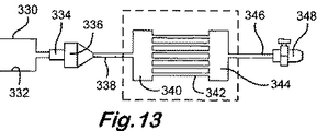
図12及び13を参照すると、ライン330内のガスとライン332内の空気が燃焼空間336内のバーナ334に供給される。燃焼の生成物は、ライン338を介して熱交換パイプアレイ342のマニホルド340に供給される。熱交換後のアレイ342からのガスは、燃焼空間内のガスと共に、マニホルド344及びライン346を介して任意のファン348へと抽出され、続いて放出される。一般に、バーナ344に供給されるガス混合物は約300%過剰に空気混和されることで、熱交換器チューブを通過する燃焼生成物の温度を和らげ、かつ、熱交換器チューブの堅固さ(hardness)と脆化(embrittlement)を和らげている。何らかの特別な設備に必要とされる伝熱特性に依存して、アレイ342のチューブは平坦であってもよく、フィンを備えていてもよく、これは第2の熱交換器のチューブも同様である。各区域の冷却器は、インペラー308の上流側か下流側であって床318の下方に配置された、1個またはそれ以上の水充填型(water-filled)冷却チューブアレイであってもよく、又は、壁320a、320bと断熱材316との間に配置されるカスゲート冷却チューブ(serpentine tube)314c(平坦、又は冷却フィン付き)であってもよく、又は、熱交換器312a−312eの上流又は下流であって天井322の上方空間内に配置されてもよい。
Referring to FIGS. 12 and 13, the gas in
Claims (46)
前記パネルをその成形用の成形ツールに接触させることによってロードを生成することと、
体積が250立方メートルよりも大きく、ロード空間のアスペクト比が3よりも大きなオートクレーブ内で前記ロードを熱処理することとを備えており、
前記製品の最長寸法が前記オートクレーブの軸に対して一般に平行に向いており、前記パネル及び前記成形ツールが前記オートクレーブの内部空間のより大きい部分に沿って延びており、前記ロードの熱特性が前記ロードに沿った位置で変化し、前記オートクレーブはその長さに沿って配置された複数の気体循環手段を有し、該気体循環手段のそれぞれが、前記ロード上に非軸方向にぶつかるようになされた加熱気体循環であって、前記ロードをその長さに沿って異なる温度で、及び/又は気体循環の異なる速度で加熱するようになされた加熱気体循環、のための区域を生成することにより、前記ロード全体の温度が均一の速度で上昇するようにした方法。A method of forming a panel having an elongated shape,
Generating a load by contacting the panel with a molding tool for the molding;
Heat treating the load in an autoclave having a volume greater than 250 cubic meters and an aspect ratio of the load space greater than 3.
The longest dimension of the product is oriented generally parallel to the axis of the autoclave, the panel and the molding tool extend along a larger portion of the interior space of the autoclave, and the thermal characteristics of the load are The autoclave has a plurality of gas circulation means disposed along its length, each of the gas circulation means being adapted to collide non-axially on the load. a heated gas circulation was, at different temperatures along the load to its length, and / or made a heated gas circulation as heating at different speeds of gas circulation, by generating an area for, A method in which the temperature of the entire load is increased at a uniform rate.
前記パネルは前記成形ツールの上面上にあり、そして、加熱気体が前記ツールの下側にぶつかる請求項2記載の方法。The panel is made of resin reinforced carbon fiber or other composite material for airliner, large but negligible compared to the molding tool,
The method of claim 2, wherein the panel is on the top surface of the forming tool and heated gas strikes the underside of the tool.
加圧可能な加熱室を規定するシェルと、
該シェル内においてロード空間を規定する手段と、
前記加熱室を閉じ、かつ前記ロード空間へのロードの導入と前記ロード空間からのロードの放出を許可するための少なくとも1つのドアと、
前記ロード空間内で気体を加熱するための加熱手段と、
それぞれが前記ロード空間の各区域内における非軸方向の気体循環のために、前記加熱室に沿って所々に離れて配置された複数のインペラー及びそれぞれの駆動手段と、
個々の区域内の気体に摩擦熱を調整可能に与えるよう、1又はそれ以上の区域における前記駆動手段を制御するための制御手段と、
を備えたオートクレーブ。An autoclave for heat treating the load,
A shell defining a pressurizing heating chamber;
Means for defining a load space within the shell;
At least one door for closing the heating chamber and permitting the introduction of the load into the load space and the discharge of the load from the load space;
Heating means for heating the gas in the load space;
For each non-axial gas circulation that put in each zone of the load space, a plurality of impellers and respective driving means which are spaced apart in places along the heating chamber,
Control means for controlling the drive means in one or more zones to adjustably provide frictional heat to the gas in the individual zones;
Autoclave with
Applications Claiming Priority (2)
| Application Number | Priority Date | Filing Date | Title |
|---|---|---|---|
| GB0126837A GB2381764A (en) | 2001-11-08 | 2001-11-08 | Autoclave suitable for heat treating parts |
| PCT/GB2002/005064 WO2003039731A1 (en) | 2001-11-08 | 2002-11-08 | Multiple zone autoclaves |
Publications (3)
| Publication Number | Publication Date |
|---|---|
| JP2005507774A JP2005507774A (en) | 2005-03-24 |
| JP2005507774A5 JP2005507774A5 (en) | 2005-12-22 |
| JP4326335B2 true JP4326335B2 (en) | 2009-09-02 |
Family
ID=9925398
Family Applications (1)
| Application Number | Title | Priority Date | Filing Date |
|---|---|---|---|
| JP2003541617A Expired - Fee Related JP4326335B2 (en) | 2001-11-08 | 2002-11-08 | Multi-area autoclave |
Country Status (10)
| Country | Link |
|---|---|
| US (1) | US6872918B2 (en) |
| EP (2) | EP1427518B1 (en) |
| JP (1) | JP4326335B2 (en) |
| KR (1) | KR20050056933A (en) |
| CN (1) | CN1284618C (en) |
| AT (1) | ATE293010T1 (en) |
| DE (1) | DE60203724T2 (en) |
| ES (2) | ES2238612T3 (en) |
| GB (1) | GB2381764A (en) |
| WO (1) | WO2003039731A1 (en) |
Cited By (1)
| Publication number | Priority date | Publication date | Assignee | Title |
|---|---|---|---|---|
| US9586345B2 (en) | 2011-02-21 | 2017-03-07 | Mitsubishi Heavy Industries, Ltd. | Autoclave and method for heat curing molded material |
Families Citing this family (30)
| Publication number | Priority date | Publication date | Assignee | Title |
|---|---|---|---|---|
| GB2416326A (en) * | 2004-07-17 | 2006-01-25 | Aeroform Group Plc | Autoclave treatment of large hollow articles |
| AU2005279145A1 (en) * | 2004-09-01 | 2006-03-09 | Shell Internationale Research Maatschappij B.V. | Horizontal reactor vessel |
| US8876999B2 (en) * | 2007-06-12 | 2014-11-04 | The Boeing Company | Flexible shape low volume autoclave |
| US8910688B2 (en) | 2007-06-12 | 2014-12-16 | The Boeing Company | Low volume autoclave having configurable shape |
| GB0802388D0 (en) * | 2008-02-11 | 2008-03-12 | Parry Julian D | The joint technologies protocol |
| US20110127252A1 (en) * | 2009-11-27 | 2011-06-02 | Tangteck Equipment Inc. | Heating device having a function of dynamical temperature-control |
| US9127888B2 (en) | 2010-07-02 | 2015-09-08 | Asc Process Systems | Industrial oven for curing composite material structures |
| US8457937B2 (en) | 2011-01-03 | 2013-06-04 | General Electric Company | Method of optimizing volume utilization of an autoclave |
| CN102700035B (en) * | 2011-01-17 | 2014-09-24 | 潍坊跃龙橡胶有限公司 | Intermittent hot water circulation pressure stabilization insulation tyre vulcanization technology |
| KR101083780B1 (en) * | 2011-05-25 | 2011-11-18 | 주식회사 삼인이엔지 | Autoclave and opening and shutting apparatus thereof |
| ITTO20111091A1 (en) * | 2011-11-28 | 2013-05-29 | Fater Spa | EQUIPMENT AND PROCEDURE FOR THE RECYCLING OF ABSORBENT SANITARY PRODUCTS |
| US20140023757A1 (en) * | 2012-07-17 | 2014-01-23 | Honeyville Grain, Inc. | Thermal processes of reducing foodborne pathogens in bagged food products |
| CN103553017B (en) * | 2013-10-14 | 2015-09-16 | 南京大学 | One step prepares the method and apparatus of fluorine, the two oxygen-doped functionalized graphene of nitrogen |
| ITBR20130005A1 (en) * | 2013-12-17 | 2015-06-18 | Epi Srl | AUTOCLAVE FOR COMPOSITE MATERIALS |
| FR3016812B1 (en) | 2014-01-29 | 2020-10-23 | Steriflow | ARTICLE HEAT TREATMENT SYSTEM |
| KR101602187B1 (en) | 2014-12-24 | 2016-03-10 | 한국항공우주산업 주식회사 | Thermocouple wire module |
| JP2016209776A (en) * | 2015-04-28 | 2016-12-15 | チョ,ヒョンジン | Autoclave |
| US10203157B2 (en) * | 2015-05-26 | 2019-02-12 | The Boeing Company | Airflow in autoclaves |
| US10309726B2 (en) * | 2015-09-29 | 2019-06-04 | The Boeing Company | Hinged baffle for autoclave that deploys at a target temperature during a run cycle |
| EP3205468B1 (en) * | 2016-02-12 | 2022-07-27 | Lightweight Labs, LLC | Air impingement device, system and method for thermal processing and consolidation |
| DE102016119703A1 (en) * | 2016-10-17 | 2018-04-19 | Kraussmaffei Technologies Gmbh | Method and device for producing molded parts with a semi-finished product |
| US10994449B2 (en) * | 2017-02-13 | 2021-05-04 | Lightweight Labs, Llc | Air impingement device, system and method for thermal processing and consolidation |
| WO2019084618A1 (en) * | 2017-11-02 | 2019-05-09 | Furnace Engineering Pty Ltd | Controlled atmosphere recirculation oven |
| US11543136B2 (en) * | 2019-01-25 | 2023-01-03 | Thermal Product Solutions | Friction heated oven |
| US11130261B2 (en) | 2019-03-28 | 2021-09-28 | The Boeing Company | Steerable heat source |
| US11161083B2 (en) | 2019-05-13 | 2021-11-02 | The Boeing Company | Autoclave plenum |
| US11897787B2 (en) * | 2020-04-29 | 2024-02-13 | Zero Discharge, LLC | Zero discharge water treatment apparatus and method |
| KR102353117B1 (en) * | 2020-06-09 | 2022-01-18 | 문경원 | Autoclave apparatus |
| US20230313292A1 (en) | 2022-03-29 | 2023-10-05 | Illumina Cambridge Limited | Chromenoquinoline dyes and uses in sequencing |
| CN115071170B (en) * | 2022-05-30 | 2023-09-29 | 南京航空航天大学 | Built-in temperature control grid of autoclave |
Family Cites Families (21)
| Publication number | Priority date | Publication date | Assignee | Title |
|---|---|---|---|---|
| CH227794A (en) * | 1942-06-06 | 1943-07-15 | Schweizerische Lokomotiv | System with horizontal autoclave. |
| GB1034722A (en) * | 1964-02-28 | 1966-07-06 | George Scott & Son London Ltd | Apparatus for heat or cold treating material under pressure |
| DE2637033C2 (en) * | 1976-08-17 | 1983-06-23 | Schmalbach-Lubeca Gmbh, 3300 Braunschweig | Overpressure autoclave that can be operated with a mixture of steam and air |
| DE2805915C3 (en) * | 1978-02-13 | 1981-11-05 | Dynamit Nobel Ag, 5210 Troisdorf | Reactor for the oxidation of mixtures of p-xylene and p-toluic acid methyl ester with oxygen-containing gases in the liquid phase |
| US4188811A (en) | 1978-07-26 | 1980-02-19 | Chem-Tronics, Inc. | Metal forming methods |
| SE450912B (en) * | 1981-02-19 | 1987-08-10 | Nobuyoshi Kuboyama | PROCEDURE AND APPARATUS FOR ASTADCOM AIR CIRCULATION AND CONVECTION IN A HEATING BEACH |
| JPS5862018A (en) * | 1981-10-09 | 1983-04-13 | Kawasaki Heavy Ind Ltd | Apparatus for molding and hardening resinous composite structure |
| US4447402A (en) * | 1982-05-27 | 1984-05-08 | Devine Manufacturing Company | Autoclaves |
| GB8314390D0 (en) * | 1983-05-24 | 1983-06-29 | Toll I C | Autoclaves |
| SE450685B (en) * | 1983-09-23 | 1987-07-20 | Electrolux Ab | PROCEDURE AND DEVICE FOR HEAT TREATMENT OF GOODS |
| FR2552669B1 (en) * | 1983-10-03 | 1986-06-27 | Barriquand | IMPROVEMENTS ON AUTOCLAVES AND STERILIZATION PROCESSES WITH A GAS OR GAS-VAPOR MIXTURE |
| GB8805705D0 (en) * | 1988-03-10 | 1988-04-07 | Farleydene Ltd | Improvements in/relating to autoclaves |
| JPH0661449B2 (en) * | 1988-06-30 | 1994-08-17 | 株式会社芦田製作所 | Method and apparatus for circulating gas in autoclave |
| JPH05245361A (en) * | 1992-02-29 | 1993-09-24 | Trinity Ind Corp | Autoclave |
| JPH05329355A (en) * | 1992-05-29 | 1993-12-14 | Ashida Seisakusho:Kk | Gas circulating device of autoclave |
| EP0575646A1 (en) | 1992-06-22 | 1993-12-29 | Aliteco Ag | A method and a device for forming various workpieces |
| JPH06170209A (en) * | 1992-12-01 | 1994-06-21 | Ashida Seisakusho:Kk | Method for circulating gas in autoclave |
| DE19503620C2 (en) | 1995-02-03 | 1998-07-16 | Daimler Benz Aerospace Ag | Process for forming a plate-shaped component |
| JPH09251981A (en) * | 1996-03-14 | 1997-09-22 | Toshiba Corp | Semiconductor manufacturing equipment |
| FR2752533B1 (en) * | 1996-08-23 | 1998-09-18 | Bp Chemicals Snc | APPARATUS AND PROCESS FOR POLYMERIZATION OF OLEFINE IN GAS PHASE |
| US6240333B1 (en) | 1998-06-19 | 2001-05-29 | Lockheed Martin Corporation | Method and system for fabrication of composite parts |
-
2001
- 2001-11-08 GB GB0126837A patent/GB2381764A/en not_active Withdrawn
-
2002
- 2002-11-08 AT AT02777498T patent/ATE293010T1/en not_active IP Right Cessation
- 2002-11-08 KR KR1020047007058A patent/KR20050056933A/en not_active Application Discontinuation
- 2002-11-08 ES ES02777498T patent/ES2238612T3/en not_active Expired - Lifetime
- 2002-11-08 US US10/290,755 patent/US6872918B2/en not_active Expired - Fee Related
- 2002-11-08 WO PCT/GB2002/005064 patent/WO2003039731A1/en active IP Right Grant
- 2002-11-08 EP EP02777498A patent/EP1427518B1/en not_active Expired - Lifetime
- 2002-11-08 JP JP2003541617A patent/JP4326335B2/en not_active Expired - Fee Related
- 2002-11-08 EP EP04076390A patent/EP1462156A1/en not_active Withdrawn
- 2002-11-08 CN CNB028216210A patent/CN1284618C/en not_active Expired - Fee Related
- 2002-11-08 DE DE60203724T patent/DE60203724T2/en not_active Expired - Lifetime
- 2002-11-08 ES ES200202569A patent/ES2229864B1/en not_active Withdrawn - After Issue
Cited By (2)
| Publication number | Priority date | Publication date | Assignee | Title |
|---|---|---|---|---|
| US9586345B2 (en) | 2011-02-21 | 2017-03-07 | Mitsubishi Heavy Industries, Ltd. | Autoclave and method for heat curing molded material |
| US10029397B2 (en) | 2011-02-21 | 2018-07-24 | Mitsubishi Heavy Industries, Ltd. | Autoclave and method for heat curing molded material |
Also Published As
| Publication number | Publication date |
|---|---|
| EP1427518B1 (en) | 2005-04-13 |
| GB2381764A (en) | 2003-05-14 |
| EP1462156A1 (en) | 2004-09-29 |
| WO2003039731A1 (en) | 2003-05-15 |
| CN1284618C (en) | 2006-11-15 |
| US6872918B2 (en) | 2005-03-29 |
| KR20050056933A (en) | 2005-06-16 |
| DE60203724T2 (en) | 2005-09-01 |
| EP1427518A1 (en) | 2004-06-16 |
| JP2005507774A (en) | 2005-03-24 |
| DE60203724D1 (en) | 2005-05-19 |
| CN1578699A (en) | 2005-02-09 |
| GB0126837D0 (en) | 2002-01-02 |
| ES2229864A1 (en) | 2005-04-16 |
| US20030085219A1 (en) | 2003-05-08 |
| ATE293010T1 (en) | 2005-04-15 |
| ES2238612T3 (en) | 2005-09-01 |
| ES2229864B1 (en) | 2006-07-16 |
Similar Documents
| Publication | Publication Date | Title |
|---|---|---|
| JP4326335B2 (en) | Multi-area autoclave | |
| JP2005507774A5 (en) | ||
| US4310302A (en) | Batch coil annealing furnace baseplate | |
| EP2402692A1 (en) | Industrial oven for curing composite material structures | |
| CA2265562A1 (en) | Induction heaters to improve transitions in continuous heating systems, and method | |
| KR102309443B1 (en) | Rapid cooling structure of warm forming press molding | |
| CA2101301C (en) | Furnace shell cooling system | |
| KR101947541B1 (en) | Powder Slush Molding Machine and Powder Slush Molding Method | |
| US20170174036A1 (en) | Stabilizer manufacturing apparatus and stabilizer manufacturing method | |
| EP0333389B1 (en) | Improvements in or relating to autoclaves | |
| CN209257455U (en) | A kind of bottle blowing machine heating mechanism with bottle opening cooling device | |
| JPWO2004060630A1 (en) | Powder slush molding machine and powder slush molding method | |
| EP2776225B1 (en) | Tool element temperature control | |
| US8562333B2 (en) | Rotational molding machine and method | |
| GB2416326A (en) | Autoclave treatment of large hollow articles | |
| JP2008144215A (en) | Heat treatment device and heat treatment method for aluminum alloy material | |
| JPH06154577A (en) | Method for controlling gas temperature of autoclave | |
| EP0448960A1 (en) | Method and mould assembly for bending difficult bending shapes such as an s-shape in a glass sheet | |
| EP3205468B1 (en) | Air impingement device, system and method for thermal processing and consolidation | |
| JPH0557334B2 (en) | ||
| JP5930112B2 (en) | Resin sheet molding apparatus and molding method | |
| CN117261296A (en) | Autoclave for adjusting temperature of longitudinal countercurrent transverse heat pipe | |
| CN115747446A (en) | Be used for handling large-scale thin wall head aluminum component shape nature and regulate and control heat treatment device in coordination | |
| JP2019076736A (en) | Heating apparatus | |
| CA2729455A1 (en) | Rotational molding machine and method |
Legal Events
| Date | Code | Title | Description |
|---|---|---|---|
| A621 | Written request for application examination |
Free format text: JAPANESE INTERMEDIATE CODE: A621 Effective date: 20051102 |
|
| A131 | Notification of reasons for refusal |
Free format text: JAPANESE INTERMEDIATE CODE: A131 Effective date: 20081202 |
|
| A601 | Written request for extension of time |
Free format text: JAPANESE INTERMEDIATE CODE: A601 Effective date: 20090227 |
|
| A602 | Written permission of extension of time |
Free format text: JAPANESE INTERMEDIATE CODE: A602 Effective date: 20090306 |
|
| A521 | Request for written amendment filed |
Free format text: JAPANESE INTERMEDIATE CODE: A523 Effective date: 20090331 |
|
| TRDD | Decision of grant or rejection written | ||
| A01 | Written decision to grant a patent or to grant a registration (utility model) |
Free format text: JAPANESE INTERMEDIATE CODE: A01 Effective date: 20090512 |
|
| A01 | Written decision to grant a patent or to grant a registration (utility model) |
Free format text: JAPANESE INTERMEDIATE CODE: A01 |
|
| A61 | First payment of annual fees (during grant procedure) |
Free format text: JAPANESE INTERMEDIATE CODE: A61 Effective date: 20090609 |
|
| FPAY | Renewal fee payment (event date is renewal date of database) |
Free format text: PAYMENT UNTIL: 20120619 Year of fee payment: 3 |
|
| R150 | Certificate of patent or registration of utility model |
Free format text: JAPANESE INTERMEDIATE CODE: R150 |
|
| FPAY | Renewal fee payment (event date is renewal date of database) |
Free format text: PAYMENT UNTIL: 20130619 Year of fee payment: 4 |
|
| R250 | Receipt of annual fees |
Free format text: JAPANESE INTERMEDIATE CODE: R250 |
|
| R250 | Receipt of annual fees |
Free format text: JAPANESE INTERMEDIATE CODE: R250 |
|
| R250 | Receipt of annual fees |
Free format text: JAPANESE INTERMEDIATE CODE: R250 |
|
| LAPS | Cancellation because of no payment of annual fees |