JP4325827B2 - Fluid circuit device - Google Patents
Fluid circuit device Download PDFInfo
- Publication number
- JP4325827B2 JP4325827B2 JP2000543709A JP2000543709A JP4325827B2 JP 4325827 B2 JP4325827 B2 JP 4325827B2 JP 2000543709 A JP2000543709 A JP 2000543709A JP 2000543709 A JP2000543709 A JP 2000543709A JP 4325827 B2 JP4325827 B2 JP 4325827B2
- Authority
- JP
- Japan
- Prior art keywords
- fluid circuit
- fluid
- temperature
- diesel engine
- circuit device
- Prior art date
- Legal status (The legal status is an assumption and is not a legal conclusion. Google has not performed a legal analysis and makes no representation as to the accuracy of the status listed.)
- Expired - Lifetime
Links
- 239000012530 fluid Substances 0.000 title claims abstract description 208
- 230000004044 response Effects 0.000 claims abstract description 16
- 238000001816 cooling Methods 0.000 claims description 42
- 238000010438 heat treatment Methods 0.000 claims description 14
- 238000002485 combustion reaction Methods 0.000 claims description 5
- 230000003247 decreasing effect Effects 0.000 claims description 3
- 239000007788 liquid Substances 0.000 claims description 3
- 238000000034 method Methods 0.000 claims 1
- XLYOFNOQVPJJNP-UHFFFAOYSA-N water Substances O XLYOFNOQVPJJNP-UHFFFAOYSA-N 0.000 description 36
- 230000005611 electricity Effects 0.000 description 2
- 239000013535 sea water Substances 0.000 description 2
- RTAQQCXQSZGOHL-UHFFFAOYSA-N Titanium Chemical compound [Ti] RTAQQCXQSZGOHL-UHFFFAOYSA-N 0.000 description 1
- 239000000498 cooling water Substances 0.000 description 1
- 239000010687 lubricating oil Substances 0.000 description 1
- 238000012423 maintenance Methods 0.000 description 1
- 230000002093 peripheral effect Effects 0.000 description 1
- 230000006903 response to temperature Effects 0.000 description 1
- 229910052719 titanium Inorganic materials 0.000 description 1
- 239000010936 titanium Substances 0.000 description 1
Images


Classifications
-
- F—MECHANICAL ENGINEERING; LIGHTING; HEATING; WEAPONS; BLASTING
- F02—COMBUSTION ENGINES; HOT-GAS OR COMBUSTION-PRODUCT ENGINE PLANTS
- F02N—STARTING OF COMBUSTION ENGINES; STARTING AIDS FOR SUCH ENGINES, NOT OTHERWISE PROVIDED FOR
- F02N19/00—Starting aids for combustion engines, not otherwise provided for
- F02N19/02—Aiding engine start by thermal means, e.g. using lighted wicks
- F02N19/04—Aiding engine start by thermal means, e.g. using lighted wicks by heating of fluids used in engines
- F02N19/10—Aiding engine start by thermal means, e.g. using lighted wicks by heating of fluids used in engines by heating of engine coolants
-
- F—MECHANICAL ENGINEERING; LIGHTING; HEATING; WEAPONS; BLASTING
- F01—MACHINES OR ENGINES IN GENERAL; ENGINE PLANTS IN GENERAL; STEAM ENGINES
- F01P—COOLING OF MACHINES OR ENGINES IN GENERAL; COOLING OF INTERNAL-COMBUSTION ENGINES
- F01P7/00—Controlling of coolant flow
- F01P7/14—Controlling of coolant flow the coolant being liquid
- F01P7/16—Controlling of coolant flow the coolant being liquid by thermostatic control
- F01P7/165—Controlling of coolant flow the coolant being liquid by thermostatic control characterised by systems with two or more loops
-
- F—MECHANICAL ENGINEERING; LIGHTING; HEATING; WEAPONS; BLASTING
- F02—COMBUSTION ENGINES; HOT-GAS OR COMBUSTION-PRODUCT ENGINE PLANTS
- F02B—INTERNAL-COMBUSTION PISTON ENGINES; COMBUSTION ENGINES IN GENERAL
- F02B29/00—Engines characterised by provision for charging or scavenging not provided for in groups F02B25/00, F02B27/00 or F02B33/00 - F02B39/00; Details thereof
- F02B29/04—Cooling of air intake supply
- F02B29/0406—Layout of the intake air cooling or coolant circuit
- F02B29/0437—Liquid cooled heat exchangers
- F02B29/0443—Layout of the coolant or refrigerant circuit
-
- F—MECHANICAL ENGINEERING; LIGHTING; HEATING; WEAPONS; BLASTING
- F02—COMBUSTION ENGINES; HOT-GAS OR COMBUSTION-PRODUCT ENGINE PLANTS
- F02B—INTERNAL-COMBUSTION PISTON ENGINES; COMBUSTION ENGINES IN GENERAL
- F02B29/00—Engines characterised by provision for charging or scavenging not provided for in groups F02B25/00, F02B27/00 or F02B33/00 - F02B39/00; Details thereof
- F02B29/04—Cooling of air intake supply
- F02B29/0493—Controlling the air charge temperature
-
- F—MECHANICAL ENGINEERING; LIGHTING; HEATING; WEAPONS; BLASTING
- F01—MACHINES OR ENGINES IN GENERAL; ENGINE PLANTS IN GENERAL; STEAM ENGINES
- F01P—COOLING OF MACHINES OR ENGINES IN GENERAL; COOLING OF INTERNAL-COMBUSTION ENGINES
- F01P5/00—Pumping cooling-air or liquid coolants
- F01P5/10—Pumping liquid coolant; Arrangements of coolant pumps
- F01P2005/105—Using two or more pumps
-
- F—MECHANICAL ENGINEERING; LIGHTING; HEATING; WEAPONS; BLASTING
- F01—MACHINES OR ENGINES IN GENERAL; ENGINE PLANTS IN GENERAL; STEAM ENGINES
- F01P—COOLING OF MACHINES OR ENGINES IN GENERAL; COOLING OF INTERNAL-COMBUSTION ENGINES
- F01P5/00—Pumping cooling-air or liquid coolants
- F01P5/10—Pumping liquid coolant; Arrangements of coolant pumps
- F01P5/12—Pump-driving arrangements
- F01P2005/125—Driving auxiliary pumps electrically
-
- F—MECHANICAL ENGINEERING; LIGHTING; HEATING; WEAPONS; BLASTING
- F01—MACHINES OR ENGINES IN GENERAL; ENGINE PLANTS IN GENERAL; STEAM ENGINES
- F01P—COOLING OF MACHINES OR ENGINES IN GENERAL; COOLING OF INTERNAL-COMBUSTION ENGINES
- F01P2031/00—Fail safe
- F01P2031/32—Deblocking of damaged thermostat
-
- F—MECHANICAL ENGINEERING; LIGHTING; HEATING; WEAPONS; BLASTING
- F01—MACHINES OR ENGINES IN GENERAL; ENGINE PLANTS IN GENERAL; STEAM ENGINES
- F01P—COOLING OF MACHINES OR ENGINES IN GENERAL; COOLING OF INTERNAL-COMBUSTION ENGINES
- F01P2060/00—Cooling circuits using auxiliaries
- F01P2060/02—Intercooler
-
- F—MECHANICAL ENGINEERING; LIGHTING; HEATING; WEAPONS; BLASTING
- F01—MACHINES OR ENGINES IN GENERAL; ENGINE PLANTS IN GENERAL; STEAM ENGINES
- F01P—COOLING OF MACHINES OR ENGINES IN GENERAL; COOLING OF INTERNAL-COMBUSTION ENGINES
- F01P2060/00—Cooling circuits using auxiliaries
- F01P2060/18—Heater
-
- F—MECHANICAL ENGINEERING; LIGHTING; HEATING; WEAPONS; BLASTING
- F01—MACHINES OR ENGINES IN GENERAL; ENGINE PLANTS IN GENERAL; STEAM ENGINES
- F01P—COOLING OF MACHINES OR ENGINES IN GENERAL; COOLING OF INTERNAL-COMBUSTION ENGINES
- F01P7/00—Controlling of coolant flow
- F01P7/14—Controlling of coolant flow the coolant being liquid
- F01P7/16—Controlling of coolant flow the coolant being liquid by thermostatic control
- F01P7/167—Controlling of coolant flow the coolant being liquid by thermostatic control by adjusting the pre-set temperature according to engine parameters, e.g. engine load, engine speed
-
- Y—GENERAL TAGGING OF NEW TECHNOLOGICAL DEVELOPMENTS; GENERAL TAGGING OF CROSS-SECTIONAL TECHNOLOGIES SPANNING OVER SEVERAL SECTIONS OF THE IPC; TECHNICAL SUBJECTS COVERED BY FORMER USPC CROSS-REFERENCE ART COLLECTIONS [XRACs] AND DIGESTS
- Y02—TECHNOLOGIES OR APPLICATIONS FOR MITIGATION OR ADAPTATION AGAINST CLIMATE CHANGE
- Y02T—CLIMATE CHANGE MITIGATION TECHNOLOGIES RELATED TO TRANSPORTATION
- Y02T10/00—Road transport of goods or passengers
- Y02T10/10—Internal combustion engine [ICE] based vehicles
- Y02T10/12—Improving ICE efficiencies
Landscapes
- Engineering & Computer Science (AREA)
- General Engineering & Computer Science (AREA)
- Combustion & Propulsion (AREA)
- Mechanical Engineering (AREA)
- Chemical & Material Sciences (AREA)
- Thermal Sciences (AREA)
- Physics & Mathematics (AREA)
- Air-Conditioning For Vehicles (AREA)
- Output Control And Ontrol Of Special Type Engine (AREA)
- External Artificial Organs (AREA)
- Control Of Temperature (AREA)
- Fluid-Pressure Circuits (AREA)
- Absorbent Articles And Supports Therefor (AREA)
- Exhaust-Gas Circulating Devices (AREA)
- Supercharger (AREA)
Abstract
Description
【0001】
発明の属する技術分野
本発明は、本発明は、温度制御の目的に用いられる流体回路装置に関する。
【0002】
発明の背景
本発明の流体回路装置は、温度制御を必要とする任意の環境において使用することができる。この温度制御には、流体回路装置自体内の流体の温度の制御だけでなく、その流体回路装置の熱交換手段内又はその外側を被って流れる第2流体の温度を制御することも含まれる。
【0003】
第1流体と第2流体は、同じであっても、異なるものであってもよいが、本発明は、第1流体が水等の液体であり、第2流体がガス、特に空気である場合を特に企図している。
【0004】
本発明の流体回路装置はいろいろな用途を企図しているが、本発明は、第1流体が流体回路装置内を流れる水であり、第2流体が燃焼過程に利用すべき空気であるディーゼルエンジン、内燃エンジン、ガスタービン等の原動機に組み合わせて用いるための冷却/加熱回路として特に適している。
【0005】
大馬力ディーゼルエンジンの場合を例にとると、その流体回路装置は、主エンジン温度制御システムを構成し、エンジンからその周囲へ熱を放散させるためのジャケット、クーラー又はラジエータと称される熱交換手段を備えている。高馬力ディーゼルエンジンは、必須要件として、コンプレッサからの高圧空気(チャージ空気)を吸気マニホールドを介して各燃焼シリンダ内へ導入するターボチャージャーを備えている。チャージ空気はターボチャージャーのコンプレッサによって圧縮されるとその温度が上昇する。もしチャージ空気の温度をその高温のままに放置しておいたとすると、その高圧の利点が大幅に減少されることになる。従って、通常、コンプレッサと吸気マニホールドの間に冷却手段が設けられる。そのような冷却手段(一般に、インタークーラー又はチャージ空気クーラーと称される)は、その外周面を被って通るチャージ空気から熱を奪うために水を通す熱交換装置を備えている。
【0006】
全負荷状態では、コンプレッサから吐出されたチャージ空気は、例えば210゜Cもの高い温度にあり、その温度が、チャージ空気がインタークーラーを通る間に例えば70゜C程度にまで急激に低下される。
【0007】
インタークーラーのための冷却水回路((以下、単に「インタークーラー回路」とも称する)と主エンジン冷却回路即ち主ジャケット冷却回路とを弁装置を介して相互に接続し、それによって、インタークーラー回路からの熱を主ジャケット冷却回路を通して放散させ、それらの両方の回路からの熱をインタークーラー回路内の冷却手段を介して放散させるようにすることは周知である。
【0008】
しかしながら、そのような周知のシステムは、例えばエンジンを最初に始動させるような、ある種の条件下では、温度を周囲温度より高い値に維持する方が有利あるときに、系から過度の量の熱を喪失させることを意味する。
【0009】
発明の概要
本発明は、いろいろな動作条件下において所要の温度制御を達成することができる流体回路装置を提供することを目的とする。
【0010】
この目的を達成するために、本発明によれば、内部を通して第1流体を循環させる第1流体回路及び第2流体回路と、該第1流体回路と第2流体回路を相互に接続する相互接続手段とから成る流体回路装置であって、前記第1流体回路は、該第1流体回路とその周囲との間で熱を交換するための第1熱交換手段を含み、前記第2流体回路は、前記第1流体を制御された態様で冷却するための冷却手段と、該第2流体回路と第2流体との間で熱を交換するための第2熱交換手段と、該第1流体回路内の少くとも温度に応答して該冷却手段を通る第1流体の流れを制御する制御手段によって作動される弁装置を含み、該第1流体回路と第2流体回路の少くとも一方が該第1流体を加熱するための加熱手段を含むことを特徴とする流体回路装置が提供される。
【0011】
前記制御された態様での冷却中、前記第1流体回路及び第2流体回路の両方を通って循環する前記第1流体を前記冷却手段に通すように構成することが好ましい。
【0012】
前記第1流体回路及び第2流体回路には、いずれも、それぞれ独自の前記加熱手段を設けることができる。
【0013】
前記加熱手段は、それぞれ独自のサーモスタットを備えた独自の電気ヒーターによって構成することができる。
【0014】
前記制御手段は、前記第2熱交換手段を通る前記第2流体の温度にも応答して作動するように構成することができる。
【0015】
前記弁装置は、2つの入口ポートと、1つの出口ポートと、該2つの入口ポートの一方を漸進的に閉鎖するにつれて他方の入口ポートを漸進的に開放するように前記制御手段の制御によって移動される弁部材から成るものであることが好ましい。一方の入口ポートが漸進的に閉鎖され、他方の入口ポートが漸進的に開放される間、前記第1流体が前記冷却手段を通して通流せしめられる。
【0016】
前記制御手段は、前記第1流体回路内の第1流体の温度範囲及び、又は前記第2熱交換手段内の第2流体の温度範囲に応答して前記弁装置を漸進的に作動させることができる。
前記第1流体回路及び第2流体回路内を循環する前記第1流体は、液体であることが好ましい。
【0017】
前記相互接続手段は、所定の温度において前記2つの流体回路を相互に接続する働きをする温度応答弁装置を含むものとすることができ、該温度応答弁装置は、前記第1流体回路内の温度が所定の温度範囲に亘って増大するにつれて該第1流体回路を前記第2流体回路に漸進的に接続するように漸進的に作動されるようにする。
【0018】
上述した本発明の流体回路装置は、ディーゼルエンジンと組み合わせることができる。そのような組み合わせにおいては、前記第1熱交換手段は、ジャケット冷却手段を含み、前記第2熱交換手段は、コンプレッサと該ディーゼルエンジンの吸気マニホルドとの間のインタークーラーを含むものとすることができる。該ディーゼルエンジンの待機(スタンバイ)状態中、前記加熱手段は、前記第1流体回路内の温度を第1所定温度以上に維持し、前記第2流体回路内の温度を第2所定温度以上に維持するように作動することができる。前記第2所定温度は、前記第1所定温度より高い温度とする。前記制御手段は、前記インタークーラー内の温度及び、又は該インタークーラー内の圧力及び、又は該ディーゼルエンジンの速度に応答して作動することができる。更に、該制御手段は、該ディーゼルエンジンの増大する負荷に応答して前記弁装置を漸進的に作動させて前記冷却手段を流体回路内へ導入し、前記第2流体回路内を流れている流体を該冷却手段を介して冷却することができる。更に、該制御手段は、該ディーゼルエンジンの低負荷及び、又は減少する負荷に応答して前記弁装置を漸進的に作動させて前記冷却手段を流体回路から離脱させることができる。
【0019】
発明の実施形態の説明
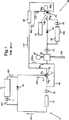
以下に、添付図を参照して本発明の実施形態を説明する。図1、2、3は、特にディーゼルエンジンに使用するための流体回路装置の実施形態を示す。図1には、この流体回路装置の基本的構成が示されている。図1は、又、ディーゼルエンジンが待機(スタンバイ)状態にあるときの第1流体回路内の流体の流れを矢印101で示し、第2流体回路内の流体の流れを矢印102で示している。待機状態では、エンジンは、実際に作動しておらず、即座に始動できる準備状態にある。
【0020】
図2は、エンジンが低負荷状態にあり、負荷が増大する条件下で作動しているときの第1流体回路内の流体の流れを矢印201で示し、第2流体回路内の流体の流れを矢印202で示している。
【0021】
図3は、エンジンが平常運転状態である高負荷条件下で作動しているときの第1流体回路内の流体の流れを矢印301で示し、第2流体回路内の流体の流れを矢印302で示している。
【0022】
以下に、図示の流体回路装置を例えば船舶に搭載される大馬力ディーゼルエンジンに使用する場合に関連して説明するが、この流体回路装置は、例えば内燃エンジンや、ガスタービンや、その他の原動機、又は精巧な温度制御装置を必要とする他の任意の環境において利用することができる。
【0023】
ここに例示した本発明の流体回路装置は、ポンプ11,12によって水を循環させる第1流体回路10を含む。ポンプ11,12は、任意の適当な手段、例えばエンジンが運転しているときはエンジンによって、エンジンが待機状態にあるときは電気によって駆動される。第1流体回路10は、又、該回路とその周囲(後述する)との間で熱を交換する働きをする第1熱交換手段13(例えば、エンジンの水ジャケット、即ちエンジンジャケット)を含む。
【0024】
第1流体回路10は、更に、その中を循環する水を第1所定温度(例えば、40°C)に維持するために循環水に熱を与えることができる加熱手段14、例えば適当な定格の電気ヒーターを含む。この目的のために(循環する水を第1所定温度に維持するために)、ヒーターは、循環水が第1所定温度に達するまで加熱し続けるように慣用の内蔵サーモスタットを有している。ディーゼルエンジンに適用される場合は、ヒーター14は、エンジンが待機状態にある間は第1流体回路10内を循環する水の温度を十分に高い温度に維持するために用いられる。この循環水の温度の維持は、エンジンの迅速な始動及び、又はエンジンの全負荷へ向かっての迅速なパワーの上昇を保証するために行われる。ヒーター14には、水の逆流を防止するためにそれと並列に逆止弁15が装着されている。
【0025】
この流体回路装置は、又、ポンプ21,22によって水を循環させる第2流体回路20を含む。ポンプ21,22は、任意の適当な手段、例えばエンジンが運転しているときはエンジンによって、エンジンが待機状態にあるときは電気によって駆動される。
【0026】
第2流体回路20は、3ポート弁17と導管19とから成る相互接続手段によって第1流体回路10に接続される。
【0027】
3ポート弁17は、ヒーター14又はエンジンジャケット13からの水を受け取るように接続された入口ポート17aを有しており、水が所定温度より冷たいときは全部の水を出口ポート17bを通して流出させ、引き続き熱交換手段13を通して第1流体回路10内を循環させる。水の温度が上昇してくるにつれて、弁ポート17bが漸進的に閉鎖され、弁ポート17cが漸進的に開放されて、水を第1流体回路10から後述する冷却手段25に向けて第2流体回路20内へ通す。
【0028】
弁17は、それを通る流れの方向を変更するように所定温度で作動するようにすることができるが、特に、膨張自在のワックス素子によって作動される弁部材を備えた比例両座弁(釣り合い弁)として機能するように企図されている。第1所定温度、例えば75°Cの温度で弁部材がポート17bを漸進的に閉鎖し始め、それと併行して(比例して)弁ポート17cが漸進的に開放され、第2所定温度、例えば85°Cの温度に達した時点で弁部材がポート17bを全閉鎖され、弁ポート17cが全開放される。弁ポート17cが開放されると、水が矢印102で示されるように第2流体回路20内を通って流れる。
【0029】
導管19は、第2流体回路20と第1流体回路10の間の接続導管を構成し、開放した弁ポート17cを通って第1流体回路10から流出した水を補充するために水を第1流体回路10へ戻すことができる。即ち、弁17を通って第2流体回路20内へ流入する「温」水と同量の「冷」水が導管19を通って第1流体回路10へ戻る。系(流体回路装置全体)内の圧力が、導管19から分岐した導管18内の流れが矢印102aで示される方向になるように規定し、それによって、水が第2流体回路20の主要部分を通らずに単に導管18と19だけを通って第1流体回路10へ戻ることがないようにする。
【0030】
第2流体回路20は、該回路から熱を放散させることができるクーラーの形の冷却手段25と、作動条件に応じて、特にエンジンが待機状態又は低負荷状態にあるか、又は、負荷増大中又は全負荷状態にあるかによって、第2流体回路20に熱を加えたり、該回路から熱を除去したりすることができるインタークーラーの形の熱交換手段26を含む。
【0031】
インタークーラー26は、ターボチャージャーのコンプレッサ27からの圧縮空気をディーゼルエンジンのシリンダーの吸気マニホールド28へ通流させる。
【0032】
第2流体回路20は、又、電気ヒーターの形の加熱手段23と、それと並列に装着された逆止弁24を含む。
【0033】
ヒーター23は、待機又は低負荷状態中、第2流体回路20内を流れる水が、待機又は低負荷条件下の第1流体回路10のための上記第1所定温度(例えば、40°C)より高い第2所定温度(例えば、70°C)以上に維持されることを保証する慣用のサーモスタットを有している。この目的のために、又、待機又は低負荷条件下で第2流体回路20から熱が失われるのを防止するために、第2流体回路20内の水の流れは、エンジンが待機状態又は低負荷状態にある間は弁装置29によってクーラー25をバイパスして通るようになされている。
【0034】
弁装置(以下、単に「弁」とも称する)29は、1つの出口ポート29aと2つの入口ポート29b,29cを有する3ポート弁(電子制御される)として例示されている。弁29の制御は、第1流体回路10内の少くとも温度に応答して作動する制御手段31によって行われる。詳述すれば、制御手段31からの信号に応答しての弁29の機能は、ポート29bを開いてポート29cを閉じることによって冷却手段25を回路20内へ作動状態に導入するか、反対にポート29bを閉じてポート29cを開くことによって冷却手段25を回路20から不作動状態へ離脱させることである。この弁は、単なるオン・オフ操作ではなく、漸進的態様で作動するようになされており、入口ポート29b,29cを開閉するために漸進的に直線運動、枢動運動又は回転運動する弁部材を有する。
【0035】
制御手段31は、第1流体回路10内の温度に応答するだけでなく、ディーゼルエンジンの他のいろいろな作動パラメータに応答するようにすることもできる。例えば、制御手段31は、インタークーラー26を通るチャージ空気の温度が例えば75°Cの温度を超えた場合、クーラー25が弁29の作動によって回路20内へ導入されるようにインタークーラー26を通るチャージ空気の温度に応答するようにすることもできる。
【0036】
制御手段31が複数の温度範囲に応答するようにすることが特に有利である。例えば、制御手段31は、第1流体回路10内の水の温度が85°C〜90°Cの制御温度範囲内に入ることに応答し、あるいは、チャージ空気の温度が75°C〜80°Cの制御温度範囲内に入ることに応答することができ、「高い方が勝ち」ベースで応答するようにすることができる。その場合、弁29は、2つの温度の一方(第1流体回路内の水の温度又はチャージ空気の温度)がその制御温度範囲内に入れば、直ちに漸進的に作動し始める。弁29は、2つの温度の一方がその制御温度範囲の最高値に達したとき、又は、エンジン速度/負荷条件が最大冷却を要求しているときは、全部の水をクーラー25へ差し向ける。
【0037】
又、チャージ空気の圧力が所定値を越えた場合、あるいは、エンジン速度がクラッチ係合状態又は負荷状態中所定値を越えた場合、クーラー25が確実に弁29の作動によって回路内へ導入されるように制御するための制御器を設けることもできる。
【0038】
制御手段31は、弁29を作動させるための信号を発生するために所定のパラメータに応答する任意の適当な装置で構成することができるが、通常は、電子回路で構成する。
【0039】
弁29は、それが万一機能不能になった場合クーラー25を回路内へ導入させるようにフェールセーフ側へ付勢されている。即ち、弁ポート29bが閉鎖され、入口ポート29cが開放されて、第2流体回路20内の水がクーラー25を通る。更に、温度入力信号が失われると、制御手段31が弁29を、クーラー25を回路内へ導入させる位置へ移動させる。そのような状況下ではアラームが作動される。
【0040】
先に述べたように、エンジンが作動していないが、即座に始動できる準備状態にある待機条件下では、両流体回路10,20は、それぞれの加熱手段によってそれぞれの待機温度に維持されている。換言すれば、水は、第1流体回路10内では40°Cの温度で循環(図1の矢印101参照)しており、第2流体回路20内では65°Cの温度で循環(図1の矢印201参照)している。
【0041】
エンジンが低負荷で作動されると(図2参照)、エンジンの温度は上昇し始め、第1流体回路10内の水の温度は、待機条件下で維持されていた40°Cを越えて上昇し、そうすると、ヒーター14はもはや回路10に熱を与える働きをしなくなり、熱は、熱交換手段13を通して周囲へ失われ、弁装置17は最終的に回路10と20を接続する働きをする。エンジンが低負荷状態で作動しているときは、圧縮されたチャージ空気は矢印203で示されるようにインタークーラー26を通して通流されるが、インタークーラー26は低負荷状態ではチャージ空気に熱を伝達しているので、ヒーター23は熱を第2流体回路20に加える働きをする。
【0042】
エンジン負荷が増大すると、エンジンによって創生される熱が両方の回路10,20内の温度を上昇させ、ヒーター23はその働きを停止し、弁装置29は第1流体回路10の温度及び、又はチャージ空気の温度に応答してポート29bを漸進的に閉鎖し、ポート29cを漸進的に開放して第1流体の流れを図3に矢印302で示されるように冷却手段25を通して通流させる。弁29は、ポート29aから流出する水の温度を、それがインタークーラー26から流出する空気の温度を例えば105°Cに維持するのに十分に高い温度となるように制御する。
【0043】
高負荷条件下では、インタークーラー26に流入してくる空気は、例えば210°Cの高い温度にあり、弁29は、ポート29aから流出する水の温度を、それが熱交換器26から流出する空気の温度を例えば70°Cに維持するのに十分に低い温度となるように制御する。換言すれば、インタークーラー26を通って流れる空気からそれを通って流れる水によって熱が奪われ、その熱が冷却手段25を介して放散される。冷却手段25は、又、開放された弁17を介して第2流体回路20に接続されている第1流体回路10内の水の冷却をも行う。
【0044】
更に、この制御手段31は、エンジンの減少する負荷に応答して弁29を漸進的に作動させ冷却手段25を回路から離脱させるように構成することができ、その場合、第2流体回路20内をなファれる流体を、その温度が十分に低下した場合加熱手段23によって加熱することができる。
【0045】
本発明の流体回路装置には、潤滑油を冷却するための手段を設けることもできる。船舶に搭載されるディーゼルエンジンの場合、最終冷却は、冷却手段25及び熱交換手段13を通して循環される海水に対して行われる。海水は上述した周囲の少くとも一部を構成する。この場合、冷却手段25及び熱交換手段13は、通常、チタン板製の部品を含む。
【図面の簡単な説明】
【図1】 図1は、本発明の流体回路装置の基本的構成を示し、ディーゼルエンジンが待機状態にあるときの第1流体回路及び第2流体回路内の流体の流れを示す。
【図2】 図2は、図1と同様の図であるが、エンジンが低負荷状態にあり、負荷が増大する条件下で作動しているときの流体回路装置の作動態様を示す。
【図3】 図3は、図1及び図2と同様の図であるが、エンジンが平常運転状態である高負荷条件下で作動しているときの流体回路装置の作動態様を示す。
【符号の説明】
10 第1流体回路
11,12 ポンプ
13 熱交換手段、エンジンジャケット、
14 加熱手段、ヒーター
15 逆止弁
17 弁装置、3ポート弁
17a 入口ポート
17b 出口ポート
18 導管
19 導管
20 第2流体回路
21,22 ポンプ
23 加熱手段、ヒーター
24 逆止弁
25 冷却手段、クーラー
26 熱交換手段、インタークーラー
27 コンプレッサ
28 吸気マニホールド
29 弁装置、弁
29a 出口ポート
29b,29c 入口ポート
31 制御手段[0001]
TECHNICAL FIELD The present invention relates to a fluid circuit device used for the purpose of temperature control.
[0002]
Background of the invention The fluid circuit device of the present invention can be used in any environment requiring temperature control. This temperature control includes not only controlling the temperature of the fluid in the fluid circuit device itself, but also controlling the temperature of the second fluid flowing in or outside the heat exchange means of the fluid circuit device.
[0003]
The first fluid and the second fluid may be the same or different, but the present invention is directed to the case where the first fluid is a liquid such as water and the second fluid is a gas, particularly air. Is specifically contemplated.
[0004]
While the fluid circuit device of the present invention is intended for various applications, the present invention relates to a diesel engine in which the first fluid is water flowing in the fluid circuit device and the second fluid is air to be used in the combustion process. It is particularly suitable as a cooling / heating circuit for use in combination with a prime mover such as an internal combustion engine or a gas turbine.
[0005]
Taking the case of a large horsepower diesel engine as an example, the fluid circuit device constitutes a main engine temperature control system and heat exchange means called a jacket, cooler or radiator for dissipating heat from the engine to its surroundings. It has. The high horsepower diesel engine is provided with a turbocharger that introduces high-pressure air (charged air) from a compressor into each combustion cylinder through an intake manifold as an essential requirement. When charge air is compressed by a turbocharger compressor, its temperature rises. If the temperature of the charge air is left at that high temperature, the advantage of the high pressure is greatly reduced. Therefore, cooling means is usually provided between the compressor and the intake manifold. Such cooling means (generally referred to as an intercooler or charge air cooler) includes a heat exchange device through which water passes to remove heat from the charge air passing over its outer peripheral surface.
[0006]
In the full load state, the charge air discharged from the compressor is at a temperature as high as 210 ° C., and the temperature is rapidly lowered to, for example, about 70 ° C. while the charge air passes through the intercooler.
[0007]
A cooling water circuit for the intercooler (hereinafter also simply referred to as “intercooler circuit”) and a main engine cooling circuit, that is, a main jacket cooling circuit, are connected to each other via a valve device, so that heat from the intercooler circuit is transferred. It is well known to dissipate through the main jacket cooling circuit so that heat from both of these circuits is dissipated through the cooling means in the intercooler circuit.
[0008]
However, such known systems, for example, when starting the engine for the first time, can cause excessive amounts of water from the system when it is advantageous to maintain the temperature above ambient temperature. Means loss of heat.
[0009]
SUMMARY OF THE INVENTION An object of the present invention is to provide a fluid circuit device capable of achieving required temperature control under various operating conditions.
[0010]
To achieve this object, according to the present invention, a first fluid circuit and a second fluid circuit that circulate a first fluid through the interior, and an interconnect that interconnects the first fluid circuit and the second fluid circuit. The first fluid circuit includes first heat exchange means for exchanging heat between the first fluid circuit and its surroundings, and the second fluid circuit comprises: A cooling means for cooling the first fluid in a controlled manner; a second heat exchange means for exchanging heat between the second fluid circuit and the second fluid; and the first fluid circuit. A valve device actuated by control means for controlling the flow of the first fluid through the cooling means in response to at least a temperature therein, wherein at least one of the first fluid circuit and the second fluid circuit is the first fluid circuit. A fluid circuit device comprising heating means for heating one fluid is provided. It is.
[0011]
During cooling in the controlled manner, the first fluid circulating through both the first fluid circuit and the second fluid circuit is preferably passed through the cooling means.
[0012]
Each of the first fluid circuit and the second fluid circuit can be provided with its own heating means.
[0013]
The heating means can be constituted by a unique electric heater provided with a unique thermostat.
[0014]
The control means may be configured to operate in response to the temperature of the second fluid passing through the second heat exchange means.
[0015]
The valve device is moved under the control of the control means so as to gradually open the other inlet port as one inlet port, one outlet port and one of the two inlet ports are gradually closed. It is preferable that it consists of a valve member. The first fluid is allowed to flow through the cooling means while one inlet port is gradually closed and the other inlet port is gradually opened.
[0016]
The control means may gradually operate the valve device in response to a temperature range of the first fluid in the first fluid circuit and / or a temperature range of the second fluid in the second heat exchange means. it can.
The first fluid circulating in the first fluid circuit and the second fluid circuit is preferably a liquid.
[0017]
The interconnect means may include a temperature responsive valve device that serves to connect the two fluid circuits to each other at a predetermined temperature, and the temperature responsive valve device has a temperature within the first fluid circuit. The first fluid circuit is progressively actuated to progressively connect to the second fluid circuit as it increases over a predetermined temperature range.
[0018]
The fluid circuit device of the present invention described above can be combined with a diesel engine. In such a combination, the first heat exchange means may include a jacket cooling means, and the second heat exchange means may include an intercooler between the compressor and the intake manifold of the diesel engine. During the standby state of the diesel engine, the heating means maintains the temperature in the first fluid circuit at a first predetermined temperature or higher and maintains the temperature in the second fluid circuit at a second predetermined temperature or higher. Can be operated to. The second predetermined temperature is higher than the first predetermined temperature. The control means may operate in response to temperature in the intercooler and / or pressure in the intercooler and / or speed of the diesel engine. In addition, the control means gradually activates the valve device in response to an increasing load of the diesel engine to introduce the cooling means into the fluid circuit, and the fluid flowing in the second fluid circuit. Can be cooled via the cooling means. Further, the control means can gradually actuate the valve device in response to low and / or decreasing loads on the diesel engine to disengage the cooling means from the fluid circuit.
[0019]
Description of Embodiments of the Invention Embodiments of the present invention will be described below with reference to the accompanying drawings. 1, 2 and 3 show embodiments of fluid circuit devices, particularly for use in diesel engines. FIG. 1 shows a basic configuration of the fluid circuit device. FIG. 1 also shows the flow of fluid in the first fluid circuit when the diesel engine is in a standby (standby) state by
[0020]
FIG. 2 shows the flow of fluid in the first fluid circuit with
[0021]
FIG. 3 shows the flow of fluid in the first fluid circuit as indicated by
[0022]
Hereinafter, the illustrated fluid circuit device will be described in connection with the use of, for example, a large horsepower diesel engine mounted on a ship. This fluid circuit device is, for example, an internal combustion engine, a gas turbine, other prime movers, Or it can be utilized in any other environment that requires sophisticated temperature control devices.
[0023]
The fluid circuit device of the present invention illustrated here includes a
[0024]
The
[0025]
The fluid circuit device also includes a
[0026]
The
[0027]
The three-
[0028]
The
[0029]
The
[0030]
The
[0031]
The
[0032]
The
[0033]
During the standby or low load state, the
[0034]
The valve device (hereinafter also simply referred to as “valve”) 29 is exemplified as a three-port valve (electronically controlled) having one
[0035]
The control means 31 can respond not only to the temperature in the
[0036]
It is particularly advantageous for the control means 31 to respond to a plurality of temperature ranges. For example, the control means 31 responds when the temperature of the water in the
[0037]
When the charge air pressure exceeds a predetermined value, or when the engine speed exceeds a predetermined value during clutch engagement or load, the cooler 25 is reliably introduced into the circuit by the operation of the
[0038]
The control means 31 may comprise any suitable device that responds to predetermined parameters to generate a signal for actuating the
[0039]
The
[0040]
As previously mentioned, under standby conditions where the engine is not running but is ready to start immediately, both
[0041]
When the engine is operated at a low load (see FIG. 2), the temperature of the engine begins to rise, and the temperature of the water in the
[0042]
As the engine load increases, the heat generated by the engine raises the temperature in both
[0043]
Under high load conditions, the air flowing into the
[0044]
Further, the control means 31 can be configured to gradually actuate the
[0045]
The fluid circuit device of the present invention may be provided with means for cooling the lubricating oil. In the case of a diesel engine mounted on a ship, final cooling is performed on seawater circulated through the cooling means 25 and the heat exchange means 13. Seawater constitutes at least a part of the surroundings described above. In this case, the cooling means 25 and the heat exchange means 13 usually include titanium plate parts.
[Brief description of the drawings]
FIG. 1 shows a basic configuration of a fluid circuit device of the present invention, and shows a flow of fluid in a first fluid circuit and a second fluid circuit when a diesel engine is in a standby state.
FIG. 2 is a view similar to FIG. 1, but showing the operation of the fluid circuit device when the engine is in a low load condition and operating under conditions of increasing load.
FIG. 3 is a view similar to FIGS. 1 and 2, but showing the operating mode of the fluid circuit device when the engine is operating under high load conditions in normal operation.
[Explanation of symbols]
10
14 Heating means,
Claims (22)
前記第1流体回路(10)は、該第1流体回路とその周囲との間の熱交換を可能にする第1熱交換器(13)を含み、前記第2流体回路(20)は、前記第1流体を制御された態様で冷却するための冷却手段(25)と、該第2流体回路とターボチャージャーからの第2流体との間の熱交換を可能にする第2熱交換器(26)と、該冷却手段(25)を通る第1流体の流れを制御するために該第1流体回路(10)内の少なくとも温度に応答する制御手段(31)に接続された弁装置(29)を含み、前記第1流体回路は、前記第1流体を加熱するための第1ヒーター(14)を備え、前記第2流体回路は、前記第1流体を加熱するための第2ヒーター(23)を備えており、該第1ヒーター(14)は、前記第1流体回路内の第1流体を第1所定温度に維持することができるようにする制御手段を備え、該第2ヒーター(23)は、前記第2流体回路内の第1流体を該第1所定温度より高い第2所定温度に維持することができるようにする制御手段を備えていることを特徴とする流体回路装置。A first fluid circuit (10) and a second fluid circuit (20) for circulating a first fluid, placed in a heat exchange relationship with an internal combustion engine with a turbocharger, and the first fluid circuit and the second fluid circuit, A fluid circuit device comprising interconnecting means (17, 19) for interconnecting,
The first fluid circuit (10) includes a first heat exchanger (13) that allows heat exchange between the first fluid circuit and its surroundings, and the second fluid circuit (20) A cooling means (25) for cooling the first fluid in a controlled manner and a second heat exchanger (26) that allows heat exchange between the second fluid circuit and the second fluid from the turbocharger. And a valve device (29) connected to control means (31) responsive to at least temperature in the first fluid circuit (10) to control the flow of the first fluid through the cooling means (25) The first fluid circuit includes a first heater (14) for heating the first fluid, and the second fluid circuit includes a second heater (23) for heating the first fluid. It includes a first heater (14), a first fluid in the first fluid circuit first The second heater (23) is provided with a control means for maintaining a predetermined temperature, and the second heater (23) maintains the first fluid in the second fluid circuit at a second predetermined temperature higher than the first predetermined temperature. A fluid circuit device, characterized by comprising control means for making it possible.
Applications Claiming Priority (3)
| Application Number | Priority Date | Filing Date | Title |
|---|---|---|---|
| GB9807694.6 | 1998-04-14 | ||
| GB9807694A GB2338056B (en) | 1998-04-14 | 1998-04-14 | Fluid circuit arrangement |
| PCT/GB1999/001063 WO1999053178A1 (en) | 1998-04-14 | 1999-04-14 | Fluid circuit arrangement |
Publications (3)
| Publication Number | Publication Date |
|---|---|
| JP2002511548A JP2002511548A (en) | 2002-04-16 |
| JP2002511548A5 JP2002511548A5 (en) | 2006-06-01 |
| JP4325827B2 true JP4325827B2 (en) | 2009-09-02 |
Family
ID=10830159
Family Applications (1)
| Application Number | Title | Priority Date | Filing Date |
|---|---|---|---|
| JP2000543709A Expired - Lifetime JP4325827B2 (en) | 1998-04-14 | 1999-04-14 | Fluid circuit device |
Country Status (7)
| Country | Link |
|---|---|
| US (1) | US6491001B1 (en) |
| EP (1) | EP1071869B1 (en) |
| JP (1) | JP4325827B2 (en) |
| AT (1) | ATE270386T1 (en) |
| DE (1) | DE69918425T2 (en) |
| GB (1) | GB2338056B (en) |
| WO (1) | WO1999053178A1 (en) |
Cited By (1)
| Publication number | Priority date | Publication date | Assignee | Title |
|---|---|---|---|---|
| CN105134444A (en) * | 2015-09-01 | 2015-12-09 | 东风朝阳朝柴动力有限公司 | Diesel engine automatic preheating device |
Families Citing this family (17)
| Publication number | Priority date | Publication date | Assignee | Title |
|---|---|---|---|---|
| FR2844571B1 (en) * | 2002-09-18 | 2008-02-29 | Valeo Thermique Moteur Sa | CONTROL VALVE FOR A FLUID CIRCUIT AND CIRCUIT COMPRISING SAID VALVE |
| FR2846715B1 (en) * | 2002-11-04 | 2006-06-23 | Valeo Climatisation | CALORIFICALLY DELIVERY DEVICE WITH A COOLING LOOP OF A MOTOR VEHICLE ENGINE |
| US7047913B2 (en) * | 2004-02-13 | 2006-05-23 | Deere & Company | Cooling system for a vehicle |
| EP1904725A4 (en) * | 2005-01-28 | 2013-09-11 | Titan Res And Innovations Pty Ltd | Engine after-cooling system |
| FR2890606B1 (en) * | 2005-09-13 | 2008-11-07 | Renault Sas | METHOD FOR CONTROLLING A MOTOR POWERTRAIN COMPRISING TWO COOLING CIRCUITS |
| US20090020079A1 (en) * | 2005-11-10 | 2009-01-22 | BEHRmbH & Co. KG | Circulation system, mixing element |
| US7669417B2 (en) * | 2006-01-30 | 2010-03-02 | Titan Research And Innovations Pty Ltd | Engine after-cooling system |
| US20080115747A1 (en) * | 2006-10-31 | 2008-05-22 | International Engine Intellectual Property Company, Llc | Coolant controller for an internal combustion engine |
| DE102007047089B4 (en) * | 2007-10-01 | 2010-06-02 | Mtu Friedrichshafen Gmbh | Method for controlling the charge air temperature of an internal combustion engine |
| DE102007060670B4 (en) * | 2007-12-17 | 2009-11-19 | Mtu Friedrichshafen Gmbh | Method for controlling an internal combustion engine |
| US8857480B2 (en) * | 2011-01-13 | 2014-10-14 | GM Global Technology Operations LLC | System and method for filling a plurality of isolated vehicle fluid circuits through a common fluid fill port |
| KR101551097B1 (en) * | 2014-06-11 | 2015-09-08 | 현대자동차주식회사 | Heating system of hybrid vehicle |
| CN104343524B (en) * | 2014-08-28 | 2016-08-31 | 河南柴油机重工有限责任公司 | A kind of external gas machine modular cooling device and cooling means |
| EP3001006A1 (en) * | 2014-09-29 | 2016-03-30 | Wärtsilä Finland Oy | A cooling system for an internal combustion piston engine, a method of operating an internal combustion piston engine and an internal combustion piston engine |
| US20190193203A1 (en) * | 2017-12-21 | 2019-06-27 | Arcam Ab | Additive manufacturing apparatus |
| CN110609579A (en) * | 2019-09-29 | 2019-12-24 | 吉林化工学院 | Water constant temperature control method and device for engine test bed |
| CN115751424B (en) * | 2022-09-29 | 2023-08-01 | 胜利油田华海石化有限责任公司 | Heating circulation heat exchange device with guarantee clean function of quality of water |
Family Cites Families (21)
| Publication number | Priority date | Publication date | Assignee | Title |
|---|---|---|---|---|
| US2681052A (en) * | 1951-12-21 | 1954-06-15 | Thomas W Walsh | Preheater for internal-combustion engines |
| DE1451887A1 (en) | 1964-12-15 | 1969-07-31 | Daimler Benz Ag | Method and device for facilitating the starting of diesel engines |
| DE2527872C2 (en) * | 1975-06-23 | 1983-08-04 | Klöckner-Humboldt-Deutz AG, 5000 Köln | Liquid cooling system for an internal combustion engine |
| US4367699A (en) * | 1981-01-27 | 1983-01-11 | Evc Associates Limited Partnership | Boiling liquid engine cooling system |
| US4520767A (en) * | 1983-09-16 | 1985-06-04 | Cummins Engine Company | Low flow cooling system and apparatus |
| DE3447182A1 (en) * | 1984-12-22 | 1986-06-26 | Kromberg & Schubert, 5600 Wuppertal | Heater for the passenger compartment in motor vehicles |
| JPS62247113A (en) * | 1986-03-28 | 1987-10-28 | Aisin Seiki Co Ltd | Cooling system control device for internal combustion engine |
| DE3622378A1 (en) * | 1986-07-03 | 1988-01-14 | Kloeckner Humboldt Deutz Ag | COOLING SYSTEM FOR AN INTERNAL COMBUSTION ENGINE |
| DE3824412C1 (en) * | 1988-07-19 | 1989-08-24 | Mtu Friedrichshafen Gmbh | |
| US4949690A (en) * | 1989-04-20 | 1990-08-21 | Maurente Gilberto V | Electric automatic oil heating and fuel evaporating system |
| GB2234343A (en) * | 1989-07-22 | 1991-01-30 | Ford Motor Co | Engine cooling system |
| JP2712711B2 (en) * | 1990-02-16 | 1998-02-16 | 株式会社デンソー | Method and apparatus for cooling internal combustion engine |
| DE4042123A1 (en) * | 1990-12-28 | 1992-07-02 | Eberspaecher J | Coolant circuit with heater for vehicle engine |
| DE4104093A1 (en) | 1991-02-11 | 1992-08-13 | Behr Gmbh & Co | COOLING SYSTEM FOR A COMBUSTION ENGINE VEHICLE |
| US5201285A (en) * | 1991-10-18 | 1993-04-13 | Touchstone, Inc. | Controlled cooling system for a turbocharged internal combustion engine |
| US5415147A (en) | 1993-12-23 | 1995-05-16 | General Electric Company | Split temperature regulating system and method for turbo charged internal combustion engine |
| US5415417A (en) * | 1993-12-30 | 1995-05-16 | Reis, Jr.; Robert M. | Robotic amusement gaming machine |
| DE4435693A1 (en) * | 1994-10-06 | 1996-04-11 | Behr Gmbh & Co | Additional heating arrangement |
| FR2741675B1 (en) * | 1995-11-23 | 1998-01-02 | Inst Francais Du Petrole | METHOD AND DEVICE FOR AIDING THE COLD STARTING OF MOTOR VEHICLES |
| DE19633190B4 (en) * | 1996-08-17 | 2004-02-26 | Daimlerchrysler Ag | Cooling system for an internal combustion engine |
| DE19727277A1 (en) | 1997-06-27 | 1999-01-07 | Iav Motor Gmbh | Conditioning charge air of exhaust-driven turbocharger |
-
1998
- 1998-04-14 GB GB9807694A patent/GB2338056B/en not_active Expired - Lifetime
-
1999
- 1999-04-14 AT AT99918077T patent/ATE270386T1/en not_active IP Right Cessation
- 1999-04-14 WO PCT/GB1999/001063 patent/WO1999053178A1/en active IP Right Grant
- 1999-04-14 US US09/445,609 patent/US6491001B1/en not_active Expired - Lifetime
- 1999-04-14 DE DE69918425T patent/DE69918425T2/en not_active Expired - Lifetime
- 1999-04-14 JP JP2000543709A patent/JP4325827B2/en not_active Expired - Lifetime
- 1999-04-14 EP EP99918077A patent/EP1071869B1/en not_active Expired - Lifetime
Cited By (1)
| Publication number | Priority date | Publication date | Assignee | Title |
|---|---|---|---|---|
| CN105134444A (en) * | 2015-09-01 | 2015-12-09 | 东风朝阳朝柴动力有限公司 | Diesel engine automatic preheating device |
Also Published As
| Publication number | Publication date |
|---|---|
| GB2338056A (en) | 1999-12-08 |
| DE69918425D1 (en) | 2004-08-05 |
| EP1071869B1 (en) | 2004-06-30 |
| GB2338056B (en) | 2002-08-28 |
| US6491001B1 (en) | 2002-12-10 |
| DE69918425T2 (en) | 2005-08-25 |
| ATE270386T1 (en) | 2004-07-15 |
| GB9807694D0 (en) | 1998-06-10 |
| WO1999053178A1 (en) | 1999-10-21 |
| EP1071869A1 (en) | 2001-01-31 |
| JP2002511548A (en) | 2002-04-16 |
Similar Documents
| Publication | Publication Date | Title |
|---|---|---|
| JP4325827B2 (en) | Fluid circuit device | |
| US6230668B1 (en) | Locomotive cooling system | |
| US7267084B2 (en) | Cooling and preheating device | |
| US10669923B2 (en) | Combustion machine | |
| JP2712711B2 (en) | Method and apparatus for cooling internal combustion engine | |
| RU153006U1 (en) | INTERNAL COMBUSTION ENGINE (OPTIONS) | |
| KR101420887B1 (en) | Vehicle cooling system with directed flows | |
| US9452660B2 (en) | Valve system configurations for warming and cooling transmission fluid | |
| US20170241324A1 (en) | Thermal management system with heat recovery and method of making and using the same | |
| ZA200608218B (en) | Cooling system for a vehicle | |
| EP2795078B1 (en) | Arrangement and method for cooling of coolant in a cooling system in a vehicle | |
| US20060162677A1 (en) | Internal combustion engine coolant flow | |
| US20170248065A1 (en) | Thermal management system and method ofmaking and using the same | |
| US10215080B2 (en) | Systems and methods for rapid engine coolant warmup | |
| JP4387413B2 (en) | Vehicle cooling system | |
| CA2405444A1 (en) | Unified rotary flow control valve for internal combustion engine cooling system | |
| EP1918545A2 (en) | Coolant controller for an internal combustion engine | |
| CN109790773A (en) | Electric coolant pump | |
| US20090000779A1 (en) | Single-loop cooling system having dual radiators | |
| US20170030252A1 (en) | Method and Device for Ventilating a Heat Management System of an Internal Combustion Engine | |
| US5755283A (en) | Combined thermostat and selector valve arrangement for gas driven heat pump systems | |
| JP2021515138A (en) | Drive unit with integrated ORC | |
| KR20050048623A (en) | System and method for regulating the heat management of a vehicle | |
| WO2017139462A1 (en) | Coolant system for engine transmission | |
| JP2012132379A (en) | Engine cooling water device |
Legal Events
| Date | Code | Title | Description |
|---|---|---|---|
| A521 | Request for written amendment filed |
Free format text: JAPANESE INTERMEDIATE CODE: A523 Effective date: 20060328 |
|
| A621 | Written request for application examination |
Free format text: JAPANESE INTERMEDIATE CODE: A621 Effective date: 20060328 |
|
| A131 | Notification of reasons for refusal |
Free format text: JAPANESE INTERMEDIATE CODE: A131 Effective date: 20080930 |
|
| A521 | Request for written amendment filed |
Free format text: JAPANESE INTERMEDIATE CODE: A523 Effective date: 20081226 |
|
| TRDD | Decision of grant or rejection written | ||
| A01 | Written decision to grant a patent or to grant a registration (utility model) |
Free format text: JAPANESE INTERMEDIATE CODE: A01 Effective date: 20090512 |
|
| A01 | Written decision to grant a patent or to grant a registration (utility model) |
Free format text: JAPANESE INTERMEDIATE CODE: A01 |
|
| A61 | First payment of annual fees (during grant procedure) |
Free format text: JAPANESE INTERMEDIATE CODE: A61 Effective date: 20090604 |
|
| FPAY | Renewal fee payment (event date is renewal date of database) |
Free format text: PAYMENT UNTIL: 20120619 Year of fee payment: 3 |
|
| R150 | Certificate of patent or registration of utility model |
Free format text: JAPANESE INTERMEDIATE CODE: R150 |
|
| FPAY | Renewal fee payment (event date is renewal date of database) |
Free format text: PAYMENT UNTIL: 20120619 Year of fee payment: 3 |
|
| FPAY | Renewal fee payment (event date is renewal date of database) |
Free format text: PAYMENT UNTIL: 20130619 Year of fee payment: 4 |
|
| R250 | Receipt of annual fees |
Free format text: JAPANESE INTERMEDIATE CODE: R250 |
|
| R250 | Receipt of annual fees |
Free format text: JAPANESE INTERMEDIATE CODE: R250 |
|
| R250 | Receipt of annual fees |
Free format text: JAPANESE INTERMEDIATE CODE: R250 |
|
| R250 | Receipt of annual fees |
Free format text: JAPANESE INTERMEDIATE CODE: R250 |
|
| R250 | Receipt of annual fees |
Free format text: JAPANESE INTERMEDIATE CODE: R250 |
|
| R250 | Receipt of annual fees |
Free format text: JAPANESE INTERMEDIATE CODE: R250 |
|
| EXPY | Cancellation because of completion of term |