EP1071869B1 - Fluid circuit arrangement - Google Patents
Fluid circuit arrangement Download PDFInfo
- Publication number
- EP1071869B1 EP1071869B1 EP99918077A EP99918077A EP1071869B1 EP 1071869 B1 EP1071869 B1 EP 1071869B1 EP 99918077 A EP99918077 A EP 99918077A EP 99918077 A EP99918077 A EP 99918077A EP 1071869 B1 EP1071869 B1 EP 1071869B1
- Authority
- EP
- European Patent Office
- Prior art keywords
- circuit
- fluid
- temperature
- engine
- circuit arrangement
- Prior art date
- Legal status (The legal status is an assumption and is not a legal conclusion. Google has not performed a legal analysis and makes no representation as to the accuracy of the status listed.)
- Expired - Lifetime
Links
- 239000012530 fluid Substances 0.000 title claims abstract description 66
- 238000001816 cooling Methods 0.000 claims description 42
- 238000010438 heat treatment Methods 0.000 claims description 16
- 238000002485 combustion reaction Methods 0.000 claims description 5
- 239000002826 coolant Substances 0.000 claims description 5
- 230000003247 decreasing effect Effects 0.000 claims description 3
- 239000007788 liquid Substances 0.000 claims description 3
- XLYOFNOQVPJJNP-UHFFFAOYSA-N water Substances O XLYOFNOQVPJJNP-UHFFFAOYSA-N 0.000 description 32
- 239000013535 sea water Substances 0.000 description 2
- RTAQQCXQSZGOHL-UHFFFAOYSA-N Titanium Chemical compound [Ti] RTAQQCXQSZGOHL-UHFFFAOYSA-N 0.000 description 1
- 239000000498 cooling water Substances 0.000 description 1
- 230000000694 effects Effects 0.000 description 1
- 238000005461 lubrication Methods 0.000 description 1
- 230000000750 progressive effect Effects 0.000 description 1
- 230000001629 suppression Effects 0.000 description 1
- 229910052719 titanium Inorganic materials 0.000 description 1
- 239000010936 titanium Substances 0.000 description 1
Images


Classifications
-
- F—MECHANICAL ENGINEERING; LIGHTING; HEATING; WEAPONS; BLASTING
- F02—COMBUSTION ENGINES; HOT-GAS OR COMBUSTION-PRODUCT ENGINE PLANTS
- F02N—STARTING OF COMBUSTION ENGINES; STARTING AIDS FOR SUCH ENGINES, NOT OTHERWISE PROVIDED FOR
- F02N19/00—Starting aids for combustion engines, not otherwise provided for
- F02N19/02—Aiding engine start by thermal means, e.g. using lighted wicks
- F02N19/04—Aiding engine start by thermal means, e.g. using lighted wicks by heating of fluids used in engines
- F02N19/10—Aiding engine start by thermal means, e.g. using lighted wicks by heating of fluids used in engines by heating of engine coolants
-
- F—MECHANICAL ENGINEERING; LIGHTING; HEATING; WEAPONS; BLASTING
- F01—MACHINES OR ENGINES IN GENERAL; ENGINE PLANTS IN GENERAL; STEAM ENGINES
- F01P—COOLING OF MACHINES OR ENGINES IN GENERAL; COOLING OF INTERNAL-COMBUSTION ENGINES
- F01P7/00—Controlling of coolant flow
- F01P7/14—Controlling of coolant flow the coolant being liquid
- F01P7/16—Controlling of coolant flow the coolant being liquid by thermostatic control
- F01P7/165—Controlling of coolant flow the coolant being liquid by thermostatic control characterised by systems with two or more loops
-
- F—MECHANICAL ENGINEERING; LIGHTING; HEATING; WEAPONS; BLASTING
- F02—COMBUSTION ENGINES; HOT-GAS OR COMBUSTION-PRODUCT ENGINE PLANTS
- F02B—INTERNAL-COMBUSTION PISTON ENGINES; COMBUSTION ENGINES IN GENERAL
- F02B29/00—Engines characterised by provision for charging or scavenging not provided for in groups F02B25/00, F02B27/00 or F02B33/00 - F02B39/00; Details thereof
- F02B29/04—Cooling of air intake supply
- F02B29/0406—Layout of the intake air cooling or coolant circuit
- F02B29/0437—Liquid cooled heat exchangers
- F02B29/0443—Layout of the coolant or refrigerant circuit
-
- F—MECHANICAL ENGINEERING; LIGHTING; HEATING; WEAPONS; BLASTING
- F02—COMBUSTION ENGINES; HOT-GAS OR COMBUSTION-PRODUCT ENGINE PLANTS
- F02B—INTERNAL-COMBUSTION PISTON ENGINES; COMBUSTION ENGINES IN GENERAL
- F02B29/00—Engines characterised by provision for charging or scavenging not provided for in groups F02B25/00, F02B27/00 or F02B33/00 - F02B39/00; Details thereof
- F02B29/04—Cooling of air intake supply
- F02B29/0493—Controlling the air charge temperature
-
- F—MECHANICAL ENGINEERING; LIGHTING; HEATING; WEAPONS; BLASTING
- F01—MACHINES OR ENGINES IN GENERAL; ENGINE PLANTS IN GENERAL; STEAM ENGINES
- F01P—COOLING OF MACHINES OR ENGINES IN GENERAL; COOLING OF INTERNAL-COMBUSTION ENGINES
- F01P5/00—Pumping cooling-air or liquid coolants
- F01P5/10—Pumping liquid coolant; Arrangements of coolant pumps
- F01P2005/105—Using two or more pumps
-
- F—MECHANICAL ENGINEERING; LIGHTING; HEATING; WEAPONS; BLASTING
- F01—MACHINES OR ENGINES IN GENERAL; ENGINE PLANTS IN GENERAL; STEAM ENGINES
- F01P—COOLING OF MACHINES OR ENGINES IN GENERAL; COOLING OF INTERNAL-COMBUSTION ENGINES
- F01P5/00—Pumping cooling-air or liquid coolants
- F01P5/10—Pumping liquid coolant; Arrangements of coolant pumps
- F01P5/12—Pump-driving arrangements
- F01P2005/125—Driving auxiliary pumps electrically
-
- F—MECHANICAL ENGINEERING; LIGHTING; HEATING; WEAPONS; BLASTING
- F01—MACHINES OR ENGINES IN GENERAL; ENGINE PLANTS IN GENERAL; STEAM ENGINES
- F01P—COOLING OF MACHINES OR ENGINES IN GENERAL; COOLING OF INTERNAL-COMBUSTION ENGINES
- F01P2031/00—Fail safe
- F01P2031/32—Deblocking of damaged thermostat
-
- F—MECHANICAL ENGINEERING; LIGHTING; HEATING; WEAPONS; BLASTING
- F01—MACHINES OR ENGINES IN GENERAL; ENGINE PLANTS IN GENERAL; STEAM ENGINES
- F01P—COOLING OF MACHINES OR ENGINES IN GENERAL; COOLING OF INTERNAL-COMBUSTION ENGINES
- F01P2060/00—Cooling circuits using auxiliaries
- F01P2060/02—Intercooler
-
- F—MECHANICAL ENGINEERING; LIGHTING; HEATING; WEAPONS; BLASTING
- F01—MACHINES OR ENGINES IN GENERAL; ENGINE PLANTS IN GENERAL; STEAM ENGINES
- F01P—COOLING OF MACHINES OR ENGINES IN GENERAL; COOLING OF INTERNAL-COMBUSTION ENGINES
- F01P2060/00—Cooling circuits using auxiliaries
- F01P2060/18—Heater
-
- F—MECHANICAL ENGINEERING; LIGHTING; HEATING; WEAPONS; BLASTING
- F01—MACHINES OR ENGINES IN GENERAL; ENGINE PLANTS IN GENERAL; STEAM ENGINES
- F01P—COOLING OF MACHINES OR ENGINES IN GENERAL; COOLING OF INTERNAL-COMBUSTION ENGINES
- F01P7/00—Controlling of coolant flow
- F01P7/14—Controlling of coolant flow the coolant being liquid
- F01P7/16—Controlling of coolant flow the coolant being liquid by thermostatic control
- F01P7/167—Controlling of coolant flow the coolant being liquid by thermostatic control by adjusting the pre-set temperature according to engine parameters, e.g. engine load, engine speed
-
- Y—GENERAL TAGGING OF NEW TECHNOLOGICAL DEVELOPMENTS; GENERAL TAGGING OF CROSS-SECTIONAL TECHNOLOGIES SPANNING OVER SEVERAL SECTIONS OF THE IPC; TECHNICAL SUBJECTS COVERED BY FORMER USPC CROSS-REFERENCE ART COLLECTIONS [XRACs] AND DIGESTS
- Y02—TECHNOLOGIES OR APPLICATIONS FOR MITIGATION OR ADAPTATION AGAINST CLIMATE CHANGE
- Y02T—CLIMATE CHANGE MITIGATION TECHNOLOGIES RELATED TO TRANSPORTATION
- Y02T10/00—Road transport of goods or passengers
- Y02T10/10—Internal combustion engine [ICE] based vehicles
- Y02T10/12—Improving ICE efficiencies
Definitions
- the present invention relates to a fluid circuit arrangement which is used for temperature control purposes.
- the fluid circuit arrangement may be used in any environment where temperature control is required; such control is to involve not only control of the temperature of the fluid within the circuit arrangement itself, but of a second fluid passing in, through, over or around a heat exchange means of the circuit arrangement.
- first fluid and the second fluid may be the same or different but it is particularly envisaged that the first fluid will be a liquid such as water and the second fluid will be a gas specifically air.
- the invention is particularly applicable in the context of cooling/heating circuits for use in association with prime movers such as diesel engines, internal combustion (i.c.) engines, gas turbines, etc. where the first fluid is water flowing in the circuit arrangement and the second fluid is air which is to be utilised in the combustion process.
- prime movers such as diesel engines, internal combustion (i.c.) engines, gas turbines, etc.
- the first fluid is water flowing in the circuit arrangement and the second fluid is air which is to be utilised in the combustion process.
- the fluid circuit arrangement comprises the main engine temperature control system and includes a heat exchange means which is commonly referred to as a jacket, cooler or radiator whereby heat is removed from the engine to its surroundings.
- a high power diesel engine will involve a turbocharging arrangement which involves the introduction into the combustion cylinders via the inlet manifold of air under pressure (charge air) from a compressor. As the air is compressed by the compressor of the turbocharger its temperature is raised. The benefit of the high pressure is substantially reduced if the charge air temperature is allowed to remain at this high temperature and, accordingly, the usual arrangement is to provide a cooling means between the compressor and the inlet manifold.
- a cooling means which is generally referred to as an intercooler or charge air cooler, will involve a heat exchange arrangement. through which water is passed to take heat from the charge air passing therethrough, or therearound.
- air leaving the compressor can be at a temperature which may be as high as say 210°C, which temperature is drastically reduced to say 70°C as the charge of air passes through the intercooler.
- EP-A-0499071 (Behr GmbH & Co.) deals with cooling arrangements and discusses the suppression of cooling during a warm-up phase, and also the possible use of exhaust air heat during this phase.
- DE 3447182 (Kromberg & Schubert) describes the use of additional electrical heating for heating the cabin of a car, while US-A-3397684 (Scherenberg, Daimler-Benz AG) shows coolant pre-heating for a supercharged engine.
- the present invention seeks to provide a fluid circuit arrangement where the requisite temperature control can be achieved under various operating conditions.
- the invention provides a fluid circuit arrangement comprising first and second fluid circuits in heat exchange relationship with a turbocharged internal combustion engine, an interconnecting means which selectively connects the first circuit and the second circuit, the first circuit and the second circuit having a first fluid for circulation therein as a coolant, the first circuit comprising a first heat exchange means enabling exchange of heat between the first circuit and the engine, the second circuit comprising a cooling means for controlled cooling of the first fluid and a second heat exchange means enabling exchange of heat between the second circuit and a second fluid comprising charge air from the turbocharger, the second circuit also comprising a valve device linked to valve control means responsive to at least the temperature of the fluid in the first circuit to control the flow of first fluid through the cooling means, characterized in that the first circuit comprises a first heater associated with the first heat exchanger and the second circuit comprises a second heater associated with the second heat exchanger, the first and second heaters being provided with control means enabling the fluid in the first and second circuits to be maintained above respective first and second predetermined temperatures, so that the
- the first fluid circulating in both the first circuit and the second circuit passes through the cooling means.
- Both the first circuit and the second circuit comprise respective said heating means, and the or each heating means may comprise respective electric heaters provided with respective thermostats.
- the control means may also be responsive to the temperature of the second fluid passing through the second heat exchange means.
- the valve device comprises two inlet ports and an outlet port and a valve element movable under control by the control means to progressively close one inlet port as the other inlet port is progressively opened; as the one inlet port is progressively closed and the other inlet port is progressively opened, the first fluid is caused to flow through the cooling means.
- the control means may progressively actuate the valve device in response to respective ranges of temperatures in the first circuit or in the second heat exchange means.
- the first fluid circulating in the first and second circuits is preferably a liquid.
- the interconnecting means may comprise a temperature responsive valve device which operates to interconnect the two circuits at a predetermined temperature and the temperature responsive valve device may be operated progressively to connect the first circuit to the second circuit as the temperature in the first circuit increases over a range of temperatures.
- a fluid circuit arrangement as defined above may be combined with a diesel engine.
- the first heat exchange means may comprise a jacket cooling means and the second heat exchange means may comprise an intercooler between a compressor and an inlet manifold of the engine.
- the heating means may operate whereby the temperature of the first fluid in the first circuit is maintained at or above a first predetermined temperature and the temperature of the first fluid in the second circuit is maintained at or above a second predetemined temperature; the second predetermined temperature is higher than the first predetermined temperature, and the control means may be responsive to the temperature in the intercooler and/or the pressure of air in the intercooler and/or the speed of the engine.
- control means may respond to increasing load of the engine to operate the valve device progressively to bring the cooling means into the circuit whereby the fluid flowing through the second circuit is cooled via the cooling means. Further, the control means may respond to low and/or decreasing load of the engine to operate the valve device progressively to take the cooling means out of circuit.
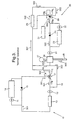
- Figure 1 there is shown the basic layout of the circuit arrangement.
- Figure 1 also shows the flow of fluid in the first circuit as represented by arrows labelled 101 and in the second circuit by arrows labelled 102, when the engine is in a standby condition. In a standby condition the engine is not actually running but is in a state ready for immediate start-up.
- Figure 2 the circuit arrangement of Figure I has arrows 201 representing fluid flow in the first circuit and arrows 202 representing fluid flow in the second circuit, when the diesel engine is operating under low and increasing load.
- arrows 301, 302 represent fluid flow in the first and second circuits respectively when the diesel engine is operating at high load, which would be under normal operation.
- the circuit arrangement as illustrated will be described for use with a large horse-power diesel engine, e.g. on a ship, although it may be utilised in other applications, e.g. with i.c. engines, gas turbines and other prime mover or in any other environment where a sophisticated temperature control arrangement is required.
- the arrangement comprises a first circuit 10 through which water is caused to circulate by pumps 11, 12 driven by any appropriate means, e.g. by the engine when it is running, or electrically when the engine is on standby.
- the circuit 10 also incorporates a first heat exchange means 13 (e.g. an engine water jacket) operable for exchange of heat between the circuit 10 and its surroundings (see below).
- the circuit 10 also includes a heating means 14, e.g. a suitably-rated electrical heater whereby heat may be added to the circulating water to maintain the temperature of the water at a first predetermined temperature (say 40°C).
- a heating means 14 e.g. a suitably-rated electrical heater whereby heat may be added to the circulating water to maintain the temperature of the water at a first predetermined temperature (say 40°C).
- the heater has a conventional built-in thermostat so that heating continues until the water reaches the first temperature.
- the heater 14 is utilised to maintain the temperature at a sufficiently high temperature during standby periods whilst the water is being circulated around the circuit 10. This is done to ensure quick start-up and/or quick build-up of engine power towards full load.
- the heater 14 has a non-retum valve 15 mounted in parallel thereto to prevent back-flow.
- the circuit arrangement also includes a second fluid circuit 20 through which water is circulated by pumps 21, 22, which are driven by appropriate means e.g. by the engine when running, or electrically.
- the second circuit 20 is connected to the first circuit 10 via an interconnecting means comprising a three-port valve 17 and a line 19.
- the three-port valve 17 has an inlet port 17 a connected to receive water flowing from heater 14 or engine jacket 13 and when the water is colder than a preset temperature all water flows out through outlet port 17 b to continue circulation around circuit 10 through heat exchange means 13. As the temperature rises valve port 17 b closes and valve port 17 c is opened so that water will flow from circuit 10 into circuit 20 towards cooling means 25 (see below).
- the valve 17 could operate at a preset temperature to change the direction of flow therethrough it is particularly envisaged that the valve will act as a proportional double beat valve having a valve member operable by expandable wax elements.
- valve member starts to progressively close off port 17 b as port 17 c is progressively opened until at a second preset temperature, say 85°C, port 17 b is fully closed and port 17 c is fully opened.
- a first preset temperature say 75 °C
- the valve member starts to progressively close off port 17 b as port 17 c is progressively opened until at a second preset temperature, say 85°C, port 17 b is fully closed and port 17 c is fully opened.
- a first preset temperature say 75 °C
- Line 19 constitutes a connecting line between circuit 20 and circuit 10 which permits water to flow back into circuit 10 to make up for water leaving circuit 10 via the opened port 17 c .
- the same quantity of 'cold' water flows back into circuit 10 via line 19 as 'hot' water flows into circuit 20 via valve 17.
- the pressures in the system ensure that flow in the line 18 which branches from line 19 is in the direction indicated by arrow 102 a so that water does not simply flow back into the first circuit via line 18 and 19 without passing through the main part of the second circuit.
- the second circuit 20 includes a cooling means 25 in the form of a cooler whereby heat may be dissipated from the circuit 20 and a heat exchange means 26 in the form of an intercooler whereby heat may be added to or taken from the circuit depending on the operating conditions, specifically whether the engine is on standby or on low-load, or increasing-load, or full-load.
- the intercooler has compressed air flowing therethrough from the compressor 27 of a turbocharger to the inlet manifold 28 of the cylinders of the diesel engine.
- the second circuit also comprises heating means 23 in the form of an electrical heater and a non-return valve 24 mounted in parallel therewith.
- the heater 23 has a conventional thermostat and acts to ensure that during standby or low load conditions the water flowing in the second circuit is maintained at or above a second predetermined temperature (say 70°C) which is higher than the first predetermined temperature (of say 40°C) for the first circuit under standby or low load conditions. To this end and to prevent heat being lost from circuit 20 in these conditions the cooler 25 is bypassed, while the engine is on standby or on low load, by a valve device 29.
- a second predetermined temperature say 70°C
- the first predetermined temperature of say 40°C
- the valve device 29 is shown as a three port (electronically-controlled) valve having an outlet port 29 a and two inlet ports 29 b , 29 c .
- Control of the valve device 29 is by means of a control means 31 which is responsive to at least the temperature in the first cooling circuit 10.
- the function of the valve 29 in response to signals from the control means 31 is to selectively bring the cooling means 25 into circuit by closing port 29 b and opening port 29 c or to take the cooling means 25 out of circuit by opening port 29 b and closing port 29 c .
- valve will operate in a progressive manner, and will comprise a valve member movable rectilinearly, pivotally or rotatably progressively to cover and uncover the inlet ports 29 b , 29 c .
- the control means as well as being responsive to the temperature in the first circuit 10, may also be responsive to various other operational parameters of the diesel engine. Specifically it may be responsive to the temperature of the charge air passing through the intercooler 26 so that if the temperature exceeds a value of say 75 °C the cooler 25 is brought into circuit by operation of the valve 29.
- control means 31 responds to ranges of temperature.
- control means may respond to the temperature of water in the first circuit being in a control range 85°- 90°C and to the charge air temperature being in a control range 75° - 80°C, the control means 31 responding on a 'highest wins' basis.
- the valve will start to progressively operate as soon as one of the temperatures (first circuit water temperature or charge air temperature) enters its respective control range. The valve will only direct all the water to the cooler when one of the temperatures reaches the top of its respective control range or when engine speed/load conditions require full cooling.
- the control means may comprise any suitable arrangement responsive to the parameters indicated to produce a control signal to operate the valve but will generally be an electronic circuit.
- valve 29 is biased to fail-safe to bring the cooler 25 into circuit should the valve fail i.e. valve port 29 b is closed and inlet port 29 c is opened whereby water circulating in the second circuit 20 passes through cooler 25. Further, loss of a temperature input signal causes the control means 31 to move the valve to its position bringing the cooler 25 into circuit. Under such conditions an alarm will operate.
- Valve 29 will control the temperature of the water leaving port 29 a such that it is at a temperature sufficiently high to maintain the temperature of the air leaving intercooler 26 at 105°C, say.
- At high load air 203 entering intercooler 26 will be at high temperature, say 210°C, and the valve 29 will control the temperature of water leaving port 29a to keep it sufficiently low to maintain the temperature of air leaving heat exchanger device 25 at 70°C.
- control means responds to decreasing load of the engine to operate the valve device 29 progressively to take the cooling means out of circuit and the fluid flowing through the second circuit may then be heated by the heating means 23 if the temperature falls sufficiently.
- the circuit arrangement may also involve means for cooling of the lubrication oil.
- final cooling is to sea water which will constitute at least part of the aforesaid surroundings, the sea water being circulated through the cooling means 25 and heat exchange means 13.
- the means 13, 25 will typically involve a titanium plate arrangement.
Abstract
Description
Claims (21)
- A fluid circuit arrangement comprising first (10) and second (20) fluid circuits in heat exchange relationship with a turbocharged internal combustion engine, an interconnecting means (17, 19) which selectively connects the first circuit and the second circuit, the first circuit and the second circuit having a first fluid for circulation therein as a coolant, the first circuit (10) comprising a first heat exchange means (13) enabling exchange of heat between the first circuit and the engine, the second circuit (20) comprising a cooling means (25) for controlled cooling of the first fluid and a second heat exchange means (26) enabling exchange of heat between the second circuit and a second fluid comprising charge air from the turbocharger, the second circuit also comprising a valve device (29) linked to valve control means (31) responsive to at least the temperature of the fluid in the first circuit (10) to control the flow of first fluid through the cooling means (25), characterized in that the first circuit comprises a first heater (14) associated with the first heat exchanger (13) and the second circuit comprises a second heater (23) associated with the second heat exchanger (26), the first and second heaters being provided with control means enabling the fluid in the first and second circuits to be maintained above respective first and second predetermined temperatures, so that the temperature of the coolant in each case is maintained at or above a predetermined temperature during standby periods and under low-load operation; and under low-load operation the second heat exchanger (26) acts to transfer heat to the charge air from the first fluid.
- A circuit arrangement as claimed in claim 1, wherein during the said controlled cooling the first fluid circulating in both the first circuit and the second circuit passes through the cooling means (25).
- A circuit arrangement as claimed in claim 1 or claim 2, wherein the interconnecting means (17, 19) connects the first circuit to the input side of the cooling means in the second circuit.
- A circuit arrangement as claimed in any preceding claim, in which both the first circuit and the second circuit include respective heating means for heating of the first fluid, these heating means comprising respective electric heaters (14, 23) provided with respective thermostats.
- A circuit arrangement as claimed in any preceding claim, wherein the control means (31) is also responsive to the temperature of the second fluid passing through the second heat exchange means (26).
- A circuit arrangement as claimed in any preceding claim, wherein the valve device (29) comprises two inlet ports (29b, 29c) and an outlet port (29a) and a valve element movable under control by the control means to close one inlet port progressively as the other inlet port is progressively opened.
- A circuit arrangement as claimed in claim 6, wherein as the one inlet port is progressively closed and the other inlet port is progressively opened, the first fluid is caused to flow through the cooling means (25).
- A circuit arrangement as claimed in any preceding claim, wherein the control means (31) is adapted to actuate the valve device (29) progressively in response to a predetermined temperature or range of temperatures of the first fluid in the first circuit (10).
- A circuit arrangement as claimed in claim 8, wherein the control means (31) is additionally adapted to actuate the valve device (29) progressively in response to a predetermined temperature or range of temperatures of the second fluid in the second circuit (20).
- A circuit arrangement as claimed in any preceding claim, wherein the first fluid circulating in the first and second circuits is a liquid.
- A circuit arrangement as claimed in any preceding claim, wherein the interconnecting means comprises a temperature-responsive valve device (17) which enables passage of the first fluid from the first circuit to the second circuit only when the fluid in the first circuit is above a preset temperature.
- A circuit arrangement as claimed in claim 11, wherein the temperature-responsive valve device (17) is constructed to operate progressively to enable passage of the first fluid from the first circuit (10) to the second circuit (20) as the temperature in the first circuit increases over a range of temperatures.
- A fluid circuit arrangement according to any preceding claim, in which the second predetermined temperature is higher than the first predetermined temperature.
- A fluid circuit arrangement according to any preceding claim, in which the interconnecting means (17, 19) is arranged to return make-up fluid from the output side of the second heat exchanger in the second circuit to the input side of the first heat exchanger in the first circuit.
- A diesel engine in combination with a fluid circuit arrangement as claimed in any preceding claim.
- A combination as claimed in claim 15, wherein the first heat exchange means comprises a jacket cooling means (13) for the engine and the second heat exchange means comprises an intercooler (26) between a compressor and an inlet manifold of the engine.
- A combination as claimed in claim 15 or claim 16, wherein the heating means is constituted in such a way that, in a standby condition of the engine, in which the engine is maintained in a state ready for immediate start-up, the temperature of the first fluid in the first circuit is maintained at or above a first predetermined temperature and the temperature of the first fluid in the second circuit is maintained at or above a second predetermined temperature.
- A combination as claimed in claim 17, wherein the second predetermined temperature is higher than the first predetermined temperature.
- A combination as claimed in any one of claims 15-18, wherein the control means is responsive to the temperature and/or the pressure of air in the intercooler (26) and/or to the speed of the engine.
- A combination as claimed in any one of claims 15-19, wherein the control means (31) is adapted to respond to increasing load of the engine to operate the valve device (29) progressively to bring the cooling means (25) into the circuit, whereby the fluid flowing through the second circuit is cooled via the cooling means.
- A combination as claimed in any one of claims 15-20, wherein the control means (31) is adapted to respond to low and/or decreasing load of the engine to operate the valve device (29) progressively to take the cooling means (25) out of circuit.
Applications Claiming Priority (3)
| Application Number | Priority Date | Filing Date | Title |
|---|---|---|---|
| GB9807694A GB2338056B (en) | 1998-04-14 | 1998-04-14 | Fluid circuit arrangement |
| GB9807694 | 1998-04-14 | ||
| PCT/GB1999/001063 WO1999053178A1 (en) | 1998-04-14 | 1999-04-14 | Fluid circuit arrangement |
Publications (2)
| Publication Number | Publication Date |
|---|---|
| EP1071869A1 EP1071869A1 (en) | 2001-01-31 |
| EP1071869B1 true EP1071869B1 (en) | 2004-06-30 |
Family
ID=10830159
Family Applications (1)
| Application Number | Title | Priority Date | Filing Date |
|---|---|---|---|
| EP99918077A Expired - Lifetime EP1071869B1 (en) | 1998-04-14 | 1999-04-14 | Fluid circuit arrangement |
Country Status (7)
| Country | Link |
|---|---|
| US (1) | US6491001B1 (en) |
| EP (1) | EP1071869B1 (en) |
| JP (1) | JP4325827B2 (en) |
| AT (1) | ATE270386T1 (en) |
| DE (1) | DE69918425T2 (en) |
| GB (1) | GB2338056B (en) |
| WO (1) | WO1999053178A1 (en) |
Cited By (1)
| Publication number | Priority date | Publication date | Assignee | Title |
|---|---|---|---|---|
| DE102007060670A1 (en) * | 2007-12-17 | 2009-08-27 | Mtu Friedrichshafen Gmbh | Method for controlling an internal combustion engine |
Families Citing this family (17)
| Publication number | Priority date | Publication date | Assignee | Title |
|---|---|---|---|---|
| FR2844571B1 (en) * | 2002-09-18 | 2008-02-29 | Valeo Thermique Moteur Sa | CONTROL VALVE FOR A FLUID CIRCUIT AND CIRCUIT COMPRISING SAID VALVE |
| FR2846715B1 (en) * | 2002-11-04 | 2006-06-23 | Valeo Climatisation | CALORIFICALLY DELIVERY DEVICE WITH A COOLING LOOP OF A MOTOR VEHICLE ENGINE |
| US7047913B2 (en) * | 2004-02-13 | 2006-05-23 | Deere & Company | Cooling system for a vehicle |
| JP2008528857A (en) * | 2005-01-28 | 2008-07-31 | タイタン・リサーチ・アンド・イノベイションズ・プロプライエタリー・リミテッド | Engine after cooling system |
| FR2890606B1 (en) * | 2005-09-13 | 2008-11-07 | Renault Sas | METHOD FOR CONTROLLING A MOTOR POWERTRAIN COMPRISING TWO COOLING CIRCUITS |
| EP1948917B1 (en) * | 2005-11-10 | 2012-08-08 | Behr GmbH & Co. KG | Circulation system, mixing element |
| US7669417B2 (en) | 2006-01-30 | 2010-03-02 | Titan Research And Innovations Pty Ltd | Engine after-cooling system |
| US20080115747A1 (en) * | 2006-10-31 | 2008-05-22 | International Engine Intellectual Property Company, Llc | Coolant controller for an internal combustion engine |
| DE102007047089B4 (en) * | 2007-10-01 | 2010-06-02 | Mtu Friedrichshafen Gmbh | Method for controlling the charge air temperature of an internal combustion engine |
| US8857480B2 (en) * | 2011-01-13 | 2014-10-14 | GM Global Technology Operations LLC | System and method for filling a plurality of isolated vehicle fluid circuits through a common fluid fill port |
| KR101551097B1 (en) * | 2014-06-11 | 2015-09-08 | 현대자동차주식회사 | Heating system of hybrid vehicle |
| CN104343524B (en) * | 2014-08-28 | 2016-08-31 | 河南柴油机重工有限责任公司 | A kind of external gas machine modular cooling device and cooling means |
| EP3001006A1 (en) * | 2014-09-29 | 2016-03-30 | Wärtsilä Finland Oy | A cooling system for an internal combustion piston engine, a method of operating an internal combustion piston engine and an internal combustion piston engine |
| CN105134444A (en) * | 2015-09-01 | 2015-12-09 | 东风朝阳朝柴动力有限公司 | Diesel engine automatic preheating device |
| US20190193203A1 (en) * | 2017-12-21 | 2019-06-27 | Arcam Ab | Additive manufacturing apparatus |
| CN110609579A (en) * | 2019-09-29 | 2019-12-24 | 吉林化工学院 | Water constant temperature control method and device for engine test bed |
| CN115751424B (en) * | 2022-09-29 | 2023-08-01 | 胜利油田华海石化有限责任公司 | Heating circulation heat exchange device with guarantee clean function of quality of water |
Citations (1)
| Publication number | Priority date | Publication date | Assignee | Title |
|---|---|---|---|---|
| US2681052A (en) * | 1951-12-21 | 1954-06-15 | Thomas W Walsh | Preheater for internal-combustion engines |
Family Cites Families (20)
| Publication number | Priority date | Publication date | Assignee | Title |
|---|---|---|---|---|
| DE1451887A1 (en) | 1964-12-15 | 1969-07-31 | Daimler Benz Ag | Method and device for facilitating the starting of diesel engines |
| DE2527872C2 (en) * | 1975-06-23 | 1983-08-04 | Klöckner-Humboldt-Deutz AG, 5000 Köln | Liquid cooling system for an internal combustion engine |
| US4367699A (en) * | 1981-01-27 | 1983-01-11 | Evc Associates Limited Partnership | Boiling liquid engine cooling system |
| US4520767A (en) * | 1983-09-16 | 1985-06-04 | Cummins Engine Company | Low flow cooling system and apparatus |
| DE3447182A1 (en) * | 1984-12-22 | 1986-06-26 | Kromberg & Schubert, 5600 Wuppertal | Heater for the passenger compartment in motor vehicles |
| JPS62247113A (en) * | 1986-03-28 | 1987-10-28 | Aisin Seiki Co Ltd | Cooling system control device for internal combustion engine |
| DE3622378A1 (en) * | 1986-07-03 | 1988-01-14 | Kloeckner Humboldt Deutz Ag | COOLING SYSTEM FOR AN INTERNAL COMBUSTION ENGINE |
| DE3824412C1 (en) * | 1988-07-19 | 1989-08-24 | Mtu Friedrichshafen Gmbh | |
| US4949690A (en) * | 1989-04-20 | 1990-08-21 | Maurente Gilberto V | Electric automatic oil heating and fuel evaporating system |
| GB2234343A (en) * | 1989-07-22 | 1991-01-30 | Ford Motor Co | Engine cooling system |
| JP2712711B2 (en) * | 1990-02-16 | 1998-02-16 | 株式会社デンソー | Method and apparatus for cooling internal combustion engine |
| DE4042123A1 (en) * | 1990-12-28 | 1992-07-02 | Eberspaecher J | Coolant circuit with heater for vehicle engine |
| DE4104093A1 (en) | 1991-02-11 | 1992-08-13 | Behr Gmbh & Co | COOLING SYSTEM FOR A COMBUSTION ENGINE VEHICLE |
| US5201285A (en) * | 1991-10-18 | 1993-04-13 | Touchstone, Inc. | Controlled cooling system for a turbocharged internal combustion engine |
| US5415147A (en) | 1993-12-23 | 1995-05-16 | General Electric Company | Split temperature regulating system and method for turbo charged internal combustion engine |
| US5415417A (en) * | 1993-12-30 | 1995-05-16 | Reis, Jr.; Robert M. | Robotic amusement gaming machine |
| DE4435693A1 (en) * | 1994-10-06 | 1996-04-11 | Behr Gmbh & Co | Additional heating arrangement |
| FR2741675B1 (en) * | 1995-11-23 | 1998-01-02 | Inst Francais Du Petrole | METHOD AND DEVICE FOR AIDING THE COLD STARTING OF MOTOR VEHICLES |
| DE19633190B4 (en) * | 1996-08-17 | 2004-02-26 | Daimlerchrysler Ag | Cooling system for an internal combustion engine |
| DE19727277A1 (en) | 1997-06-27 | 1999-01-07 | Iav Motor Gmbh | Conditioning charge air of exhaust-driven turbocharger |
-
1998
- 1998-04-14 GB GB9807694A patent/GB2338056B/en not_active Expired - Lifetime
-
1999
- 1999-04-14 EP EP99918077A patent/EP1071869B1/en not_active Expired - Lifetime
- 1999-04-14 DE DE69918425T patent/DE69918425T2/en not_active Expired - Lifetime
- 1999-04-14 WO PCT/GB1999/001063 patent/WO1999053178A1/en active IP Right Grant
- 1999-04-14 AT AT99918077T patent/ATE270386T1/en not_active IP Right Cessation
- 1999-04-14 JP JP2000543709A patent/JP4325827B2/en not_active Expired - Lifetime
- 1999-04-14 US US09/445,609 patent/US6491001B1/en not_active Expired - Lifetime
Patent Citations (1)
| Publication number | Priority date | Publication date | Assignee | Title |
|---|---|---|---|---|
| US2681052A (en) * | 1951-12-21 | 1954-06-15 | Thomas W Walsh | Preheater for internal-combustion engines |
Cited By (2)
| Publication number | Priority date | Publication date | Assignee | Title |
|---|---|---|---|---|
| DE102007060670A1 (en) * | 2007-12-17 | 2009-08-27 | Mtu Friedrichshafen Gmbh | Method for controlling an internal combustion engine |
| DE102007060670B4 (en) * | 2007-12-17 | 2009-11-19 | Mtu Friedrichshafen Gmbh | Method for controlling an internal combustion engine |
Also Published As
| Publication number | Publication date |
|---|---|
| GB2338056B (en) | 2002-08-28 |
| WO1999053178A1 (en) | 1999-10-21 |
| GB9807694D0 (en) | 1998-06-10 |
| GB2338056A (en) | 1999-12-08 |
| DE69918425T2 (en) | 2005-08-25 |
| DE69918425D1 (en) | 2004-08-05 |
| EP1071869A1 (en) | 2001-01-31 |
| JP4325827B2 (en) | 2009-09-02 |
| ATE270386T1 (en) | 2004-07-15 |
| JP2002511548A (en) | 2002-04-16 |
| US6491001B1 (en) | 2002-12-10 |
Similar Documents
| Publication | Publication Date | Title |
|---|---|---|
| EP1071869B1 (en) | Fluid circuit arrangement | |
| US7267084B2 (en) | Cooling and preheating device | |
| JP2712711B2 (en) | Method and apparatus for cooling internal combustion engine | |
| JP3179971U (en) | Combustion engine cooling system | |
| US6230668B1 (en) | Locomotive cooling system | |
| US4325219A (en) | Two loop engine coolant system | |
| US7263954B2 (en) | Internal combustion engine coolant flow | |
| US20030116105A1 (en) | Cooling circuit of a liquid-cooled internal combustion engine | |
| GB2055963A (en) | Supercharging Internal Combustion Engines | |
| GB2471514A (en) | Parallel Connected Exhaust Gas Heat Exchangers for a Motor Vehicle Engine | |
| ZA200608218B (en) | Cooling system for a vehicle | |
| EP1918545A2 (en) | Coolant controller for an internal combustion engine | |
| GB2501304A (en) | Engine system comprising coolant system having switchable coolant routes | |
| EP2795078A1 (en) | Arrangement and method for cooling of coolant in a cooling system in a vehicle | |
| CN108343500A (en) | A kind of car engine cooling system | |
| CN109139223A (en) | A kind of two-cycle engine high/low temperature cooling system | |
| JPH03500436A (en) | Cooling system for supercharged piston internal combustion engine | |
| US5755283A (en) | Combined thermostat and selector valve arrangement for gas driven heat pump systems | |
| CN109139224A (en) | A kind of engine dual cycle cooling system | |
| JP3455546B2 (en) | Multi-engine device with common fresh water cooling system | |
| JPS62298616A (en) | Engine cooling device | |
| US7249576B2 (en) | Low temperature thermostat housing system for an engine | |
| CN212671927U (en) | Engine cooling system | |
| JP3292217B2 (en) | Oil temperature control device for vehicles | |
| JP4670737B2 (en) | Engine cooling system |
Legal Events
| Date | Code | Title | Description |
|---|---|---|---|
| PUAI | Public reference made under article 153(3) epc to a published international application that has entered the european phase |
Free format text: ORIGINAL CODE: 0009012 |
|
| 17P | Request for examination filed |
Effective date: 20001013 |
|
| AK | Designated contracting states |
Kind code of ref document: A1 Designated state(s): AT BE CH DE ES FR GB IT LI NL SE |
|
| RBV | Designated contracting states (corrected) |
Designated state(s): AT BE CH DE ES FR GB IT LI NL SE |
|
| 17Q | First examination report despatched |
Effective date: 20010216 |
|
| RAP1 | Party data changed (applicant data changed or rights of an application transferred) |
Owner name: MAN B&W DIESEL LTD. |
|
| GRAP | Despatch of communication of intention to grant a patent |
Free format text: ORIGINAL CODE: EPIDOSNIGR1 |
|
| GRAS | Grant fee paid |
Free format text: ORIGINAL CODE: EPIDOSNIGR3 |
|
| GRAA | (expected) grant |
Free format text: ORIGINAL CODE: 0009210 |
|
| AK | Designated contracting states |
Kind code of ref document: B1 Designated state(s): AT BE CH DE ES FR GB IT LI NL SE |
|
| PG25 | Lapsed in a contracting state [announced via postgrant information from national office to epo] |
Ref country code: LI Free format text: LAPSE BECAUSE OF FAILURE TO SUBMIT A TRANSLATION OF THE DESCRIPTION OR TO PAY THE FEE WITHIN THE PRESCRIBED TIME-LIMIT Effective date: 20040630 Ref country code: IT Free format text: LAPSE BECAUSE OF FAILURE TO SUBMIT A TRANSLATION OF THE DESCRIPTION OR TO PAY THE FEE WITHIN THE PRE;WARNING: LAPSES OF ITALIAN PATENTS WITH EFFECTIVE DATE BEFORE 2007 MAY HAVE OCCURRED AT ANY TIME BEFORE 2007. THE CORRECT EFFECTIVE DATE MAY BE DIFFERENT FROM THE ONE RECORDED.SCRIBED TIME-LIMIT Effective date: 20040630 Ref country code: FR Free format text: LAPSE BECAUSE OF FAILURE TO SUBMIT A TRANSLATION OF THE DESCRIPTION OR TO PAY THE FEE WITHIN THE PRESCRIBED TIME-LIMIT Effective date: 20040630 Ref country code: CH Free format text: LAPSE BECAUSE OF FAILURE TO SUBMIT A TRANSLATION OF THE DESCRIPTION OR TO PAY THE FEE WITHIN THE PRESCRIBED TIME-LIMIT Effective date: 20040630 Ref country code: BE Free format text: LAPSE BECAUSE OF FAILURE TO SUBMIT A TRANSLATION OF THE DESCRIPTION OR TO PAY THE FEE WITHIN THE PRESCRIBED TIME-LIMIT Effective date: 20040630 Ref country code: AT Free format text: LAPSE BECAUSE OF FAILURE TO SUBMIT A TRANSLATION OF THE DESCRIPTION OR TO PAY THE FEE WITHIN THE PRESCRIBED TIME-LIMIT Effective date: 20040630 |
|
| REG | Reference to a national code |
Ref country code: GB Ref legal event code: FG4D Ref country code: CH Ref legal event code: EP |
|
| REF | Corresponds to: |
Ref document number: 69918425 Country of ref document: DE Date of ref document: 20040805 Kind code of ref document: P |
|
| PG25 | Lapsed in a contracting state [announced via postgrant information from national office to epo] |
Ref country code: SE Free format text: LAPSE BECAUSE OF FAILURE TO SUBMIT A TRANSLATION OF THE DESCRIPTION OR TO PAY THE FEE WITHIN THE PRESCRIBED TIME-LIMIT Effective date: 20040930 |
|
| PG25 | Lapsed in a contracting state [announced via postgrant information from national office to epo] |
Ref country code: ES Free format text: LAPSE BECAUSE OF FAILURE TO SUBMIT A TRANSLATION OF THE DESCRIPTION OR TO PAY THE FEE WITHIN THE PRESCRIBED TIME-LIMIT Effective date: 20041011 |
|
| REG | Reference to a national code |
Ref country code: CH Ref legal event code: PL |
|
| PLBE | No opposition filed within time limit |
Free format text: ORIGINAL CODE: 0009261 |
|
| STAA | Information on the status of an ep patent application or granted ep patent |
Free format text: STATUS: NO OPPOSITION FILED WITHIN TIME LIMIT |
|
| 26N | No opposition filed |
Effective date: 20050331 |
|
| EN | Fr: translation not filed | ||
| PGFP | Annual fee paid to national office [announced via postgrant information from national office to epo] |
Ref country code: NL Payment date: 20180424 Year of fee payment: 20 |
|
| PGFP | Annual fee paid to national office [announced via postgrant information from national office to epo] |
Ref country code: DE Payment date: 20180424 Year of fee payment: 20 |
|
| PGFP | Annual fee paid to national office [announced via postgrant information from national office to epo] |
Ref country code: GB Payment date: 20180423 Year of fee payment: 20 |
|
| REG | Reference to a national code |
Ref country code: DE Ref legal event code: R071 Ref document number: 69918425 Country of ref document: DE |
|
| REG | Reference to a national code |
Ref country code: NL Ref legal event code: MK Effective date: 20190413 |
|
| REG | Reference to a national code |
Ref country code: GB Ref legal event code: PE20 Expiry date: 20190413 |
|
| PG25 | Lapsed in a contracting state [announced via postgrant information from national office to epo] |
Ref country code: GB Free format text: LAPSE BECAUSE OF EXPIRATION OF PROTECTION Effective date: 20190413 |