JP4323927B2 - Image forming apparatus - Google Patents
Image forming apparatus Download PDFInfo
- Publication number
- JP4323927B2 JP4323927B2 JP2003373593A JP2003373593A JP4323927B2 JP 4323927 B2 JP4323927 B2 JP 4323927B2 JP 2003373593 A JP2003373593 A JP 2003373593A JP 2003373593 A JP2003373593 A JP 2003373593A JP 4323927 B2 JP4323927 B2 JP 4323927B2
- Authority
- JP
- Japan
- Prior art keywords
- intermediate transfer
- image forming
- image
- opening
- forming apparatus
- Prior art date
- Legal status (The legal status is an assumption and is not a legal conclusion. Google has not performed a legal analysis and makes no representation as to the accuracy of the status listed.)
- Expired - Fee Related
Links
Images


Landscapes
- Color Electrophotography (AREA)
- Electrophotography Configuration And Component (AREA)
- Electrostatic Charge, Transfer And Separation In Electrography (AREA)
Description
本発明はコンピュータ用プリンタや複写機など、静電記録方式や電子写真方式を利用したカラー画像形成装置に関するものである。 The present invention relates to a color image forming apparatus using an electrostatic recording system or an electrophotographic system, such as a printer for a computer or a copying machine.
従来、画像形成装置には、微小粉末を含む現像剤を静電的に制御吸着する静電記録方式や電子写真技術を利用した電子写真方式にて、画像形成を行なうものがある。こうした画像形成工程にて、画像形成手段によって、例えば像担持体である感光ドラムや感光ベルトの表面に静電潜像を形成する潜像形成工程、像担持体上の静電潜像を現像剤であるトナー等によって現像して可視像化し現像剤像(トナー像)とする現像工程、現像されたトナー像を転写装置により転写材上に転写して画像を担持させる転写工程、圧力や熱等を用いる定着装置によって転写材上のトナー像を転写材上に定着させる定着工程、これら各工程を順次行なうことによって画像形成物が得られる。 2. Description of the Related Art Conventionally, there are image forming apparatuses that perform image formation by an electrostatic recording method that electrostatically controls and adsorbs a developer containing fine powder or an electrophotographic method using electrophotographic technology. In such an image forming process, a latent image forming process for forming an electrostatic latent image on the surface of, for example, a photosensitive drum or a photosensitive belt, which is an image carrier, by an image forming unit; Development process with a toner or the like to make a visible image into a developer image (toner image), a transfer process in which the developed toner image is transferred onto a transfer material by a transfer device, and an image is carried, pressure or heat A fixing process that fixes the toner image on the transfer material onto the transfer material by a fixing device using the above, and an image formed product is obtained by sequentially performing these steps.
この技術を応用して、複数色の画像いわゆるカラー画像を得るためには、色の違う複数の現像剤を使用することによって可能である。原理的に、イエロー・マゼンタ・シアン色の現像剤を用いれば,混色によってフルカラーの画像を得ることができる。又、場合によって、この三種類に加えてブラック色の現像剤を用いる。 By applying this technique, a plurality of color images, so-called color images, can be obtained by using a plurality of developers having different colors. In principle, if yellow, magenta, and cyan developers are used, a full color image can be obtained by color mixing. In some cases, a black developer is used in addition to these three types.
カラー画像形成装置の構成として、現像剤を収納する現像装置を各色ごとに備え、それら複数の現像装置を直線又は曲線上に並べ、各色の現像剤に対応した静電潜像を現像させるものがある。紙やプラスチックシート等の転写材上に最終画像として得るまでの、カラー画像形成装置内の複数色画像の重ね合わせ工程の方法として、直接転写方式と中間転写方式がある。 As a configuration of a color image forming apparatus, a developing device for storing a developer is provided for each color, and the plurality of developing devices are arranged on a straight line or a curve to develop an electrostatic latent image corresponding to the developer of each color. is there. There are a direct transfer method and an intermediate transfer method as a method of superimposing a plurality of color images in a color image forming apparatus until a final image is obtained on a transfer material such as paper or a plastic sheet.
前者の直接転写方式においては、現像装置と隣接する(又は内包する)像担持体上のトナー像を転写工程で転写する対象が転写材である。即ち、直接転写方式とは、像担持体に対して転写材を接触または微小間隙にて通す際に、像担持体上の現像剤を転写材に引き寄せるように電気バイアスを形成し、像担持体から転写材に画像を直接転写させる方式である。そして、複数の現像装置及び複数の像担持体を持つカラー画像形成装置では、各色に対応する像担持体の対向する位置に転写材を移動させ、各色に対応したトナー像を転写材に順次転写する。 In the former direct transfer method, a transfer material is a target to which a toner image on an image carrier adjacent to (or included in) a developing device is transferred in a transfer process. In other words, the direct transfer method forms an electric bias so that the developer on the image carrier is attracted to the transfer material when the transfer material is brought into contact with the image carrier or through a minute gap. In this method, an image is directly transferred from a transfer material to a transfer material. In a color image forming apparatus having a plurality of developing devices and a plurality of image carriers, the transfer material is moved to the opposite position of the image carrier corresponding to each color, and the toner images corresponding to each color are sequentially transferred to the transfer material. To do.
それに対して、後者の中間転写方式では、像担持体から転写材に画像を転写する工程を実施するのに、像担持体から転写される各色のトナー像すべてを保持する第二の像担持体を用いる。即ち、転写工程においては、各色に対応したトナー像が現像された像担持体から、一旦この第二の像担持体に全てのトナー像を保持させ、第一・第二の像担持体間の転写位置より下流において第二の像担持体と転写材を接触及び接触点にて電気バイアスを形成して、第二の像担持体から転写材へ画像の転写を行なう。この第二の像担持体を中間転写体と呼ぶ場合がある。 On the other hand, in the latter intermediate transfer system, the second image carrier that holds all the toner images of the respective colors transferred from the image carrier to carry out the step of transferring the image from the image carrier to the transfer material. Is used. That is, in the transfer process, all the toner images are once held on the second image carrier from the image carrier on which the toner images corresponding to the respective colors have been developed, and the first and second image carriers are interposed. An electric bias is formed at the contact point between the second image carrier and the transfer material downstream from the transfer position, and the image is transferred from the second image carrier to the transfer material. This second image carrier is sometimes called an intermediate transfer member.
中間転写方式によるカラー画像形成装置は、直接転写方式のものより形成画像の安定性の点で有利である。なぜなら、各色に対応した像担持体上の単色トナー像を次工程で転写する際、必ず現像剤の重ね合わせを行なわなければならないが、直接転写方式では、像担持体から転写材に直接現像剤が転写されるので、転写材の物性・厚み・コシなどによって転写環境が異なり、重ね合わせに際して不安定になってしまう。転写材の搬送性も画像に影響を及ぼしてしまうからである。又、この際、転写材の吸着力によっては、既に転写材へ転写された現像剤が下流の像担持体へ逆転写してしまう恐れもある。それに対して、中間転写方式では、重ね合わせ工程での転写対象が常に同じ物体なので、安定した重ね合わせ画像を得ることができる。そして、中間転写体から転写材へは一括して画像転写されるので、最悪条件の転写材に対して転写条件を設定しておけば良い。 A color image forming apparatus using an intermediate transfer method is more advantageous in terms of stability of a formed image than that using a direct transfer method. This is because when a single color toner image on the image carrier corresponding to each color is transferred in the next step, the developer must be superimposed, but in the direct transfer method, the developer is directly applied from the image carrier to the transfer material. Since the image is transferred, the transfer environment differs depending on the physical properties, thickness, stiffness, etc. of the transfer material, and it becomes unstable upon superposition. This is because the transferability of the transfer material also affects the image. At this time, depending on the attracting force of the transfer material, the developer already transferred to the transfer material may be reversely transferred to the downstream image carrier. On the other hand, in the intermediate transfer method, since the transfer object in the overlay process is always the same object, a stable overlay image can be obtained. Since the image is transferred from the intermediate transfer member to the transfer material at once, the transfer conditions may be set for the worst-case transfer material.
中間転写体を用いたカラー画像形成装置を稼動させる際、装置本体の寿命よりも短い周期で消耗品である現像剤を使い切る場合がある。その際には、複数の現像装置において、現像剤を補給したり、もしくは現像剤を含むそれぞれの現像装置ごと取り替えたりする。 When a color image forming apparatus using an intermediate transfer member is operated, a developer that is a consumable item may be used up in a cycle shorter than the life of the apparatus main body. At that time, in a plurality of developing devices, the developer is replenished or each developing device including the developer is replaced.
しかしながら、電子写真技術を応用した現像装置及びそれに隣接した像担持体は、像担持体(第一の像担持体)に静電潜像を形成するための露光装置や、現像剤像の次工程処理が行われる中間転写体(第二の像担持体)に囲まれた状態で配置されることが多い。そのため、現像装置は装置本体の中央に配置され、使用者にとってアクセス困難な場所に配置されてしまうことが多かった。 However, the developing device applying the electrophotographic technology and the image carrier adjacent thereto are an exposure device for forming an electrostatic latent image on the image carrier (first image carrier), and the next step of the developer image. It is often arranged in a state surrounded by an intermediate transfer member (second image carrier) to be processed. For this reason, the developing device is often disposed at the center of the apparatus main body, and is disposed at a location that is difficult for the user to access.
又、画像形成中の何らかの問題により、転写材が滞留して画像形成装置本体に残留してしまう場合がある。 Also, due to some problem during image formation, the transfer material may stay and remain in the image forming apparatus main body.
転写材の搬送過程は次に述べるとおりである。転写材収納部にある未転写の転写材を中間転写体の転写ポイントまで供給する。転写ポイント通過直後には、転写材上に画像(現像剤像)が静電吸着された状態であり、現像剤を定着させるために転写材を定着装置に搬送する必要がある。尚、定着装置は、熱や圧力などを利用して、転写材上の現像剤像を構成する現像剤の溶融・押しつぶしを実施している。 The transfer material transport process is as follows. The untransferred transfer material in the transfer material storage unit is supplied to the transfer point of the intermediate transfer member. Immediately after passing the transfer point, the image (developer image) is electrostatically adsorbed on the transfer material, and it is necessary to transport the transfer material to the fixing device in order to fix the developer. Note that the fixing device uses heat, pressure, or the like to melt and crush the developer constituting the developer image on the transfer material.
ここで、この搬送過程の途中に転写材が滞留してしまうと、画像形成装置の正常稼動が行なわれなくなり、そこから復帰させるために使用者がその転写材を取り除かなければならない。 Here, if the transfer material stays in the middle of the conveyance process, the image forming apparatus cannot be operated normally, and the user has to remove the transfer material in order to return from the normal operation.
更に、中間転写体の取り扱い不具合による損傷や長時間使用による劣化等により不良画像が発生してしまうこともある。良好な画像を得るためには、中間転写体を修復するか又は新しい物と交換しなければならない。そのために、中間転写体を脱着する作業が必要である。 Furthermore, a defective image may be generated due to damage due to handling failure of the intermediate transfer member or deterioration due to long-term use. In order to obtain a good image, the intermediate transfer member must be repaired or replaced with a new one. For this purpose, it is necessary to remove the intermediate transfer member.
これらのメンテナンス性を考えた場合、特許文献1に記載されているような、図8に示す画像形成装置のように、複数の現像装置4(4Y、4M、4C、4BK)を含む画像形成部S(SY、SM、SC、SBK)を水平方向に並列配置する構成とすると、図9に示すように、上部のひとつの開閉部材(アクセスドア)11bで内部構成装置にアクセスすることができる。しかし、このことによって装置の設置面積が大きくなってしまい、設置場所が限定されたり、装置のメンテナンス等をする際に利用者が回りこまなければアクセスできない等、結果として不便さを感じさせることが多かった。 When considering these maintainability, an image forming unit including a plurality of developing devices 4 (4Y, 4M, 4C, 4BK) as in the image forming apparatus shown in FIG. When S (SY, SM, SC, SBK) is arranged in parallel in the horizontal direction, as shown in FIG. 9 , the internal component device can be accessed by one upper opening / closing member (access door) 11b. However, this increases the installation area of the device, limiting the installation location, and inconvenience as a result, such as being unable to access unless the user goes around when performing maintenance etc. of the device. There were many.
例えば、従来のカラー画像形成装置では、図8の概略断面図に示す構成のもので、装置上側から露光装置3、現像装置4、第一の像担持体である感光ドラム1(1Y、1M、1C、1BK)、中間転写体5a、転写材収納部6の順で配置されている。そして、転写材Pの搬送下流に定着装置8が配置されている。
For example, the conventional color image forming apparatus has the configuration shown in the schematic cross-sectional view of FIG. 8, and from the upper side of the apparatus, the
ここで、図9はアクセスドア11bを開けた状態を示しており、アクセスドア11b側に露光装置3が搭載され一体化されている。装置の固定側A2には各色の現像装置4や感光ドラム1等の画像形成部S、ベルト状の中間転写体5a及びその巻架ローラ5i等を含む中間転写部(中間転写ユニット)5が配置されている。つまり、上部にアクセスドア11bが配置され、中間転写ユニット5は複数の画像形成部Sの下部に配置されているため、中間転写体ユニット5を脱着する際には、図10に示すように、使用者が現像装置4と感光ドラム1等の画像形成手段を上部のアクセスドア11bを開けて一旦全て外して取り出さなければならない。図10においては、現像装置4BK、4C、そして感光ドラム1BK、1Cを画像形成装置から外した状態を示している。
Here, FIG. 9 shows a state in which the
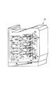
又、図11に特許文献2に記載された別の従来例の概略断面図を示す。この画像形成装置も図8に示されたのと同様に現像装置4を含む複数の画像形成部Sを水平方向に並列させた構成をとるが、ここでは、中間転写ユニット5が各画像形成部Sの上方に配置されている。図12はアクセスドア11c、11dが全て閉状態の時の斜視図であるが、この状態から、図13に示すように、水平に配列された画像形成部Sの側面の画像形成装置フレームに設けられた第一のアクセスドア11cを開けることで、各画像形成部Sそれぞれにおける各々の現像剤補給、現像装置4や像担持体1の脱着を行うことが可能である。
FIG. 11 is a schematic cross-sectional view of another conventional example described in Patent Document 2. This image forming apparatus also has a configuration in which a plurality of image forming units S including the developing device 4 are arranged in parallel in the horizontal direction, as shown in FIG. 8, but here, the
ところが、この画像形成装置において、中間転写ユニット5の脱着方向を現像装置4と同じ脱着方向にすると、画像形成装置を支持している側面のフレームに脱着のための大きな穴を設けることが必要となり、装置フレームの剛性が極端になくなってしまう。そのため中間転写ユニット5の脱着は、現像装置4を脱着する第一のドア11cとは別のもうひとつのドア11dから行なわなければならない。
However, in this image forming apparatus, when the detaching direction of the
図14は第二のアクセスドア11dを開け、中間転写ユニット5を途中まで脱着したところを示している。同様に装置フレームの剛性を確保するために、例えば、転写材のジャム処理は第二のドア11dとはちょうど反対側の第三のドア(不図示)から行なわなければならない。
FIG. 14 shows the
このように、複数の現像装置を有するカラー画像形成装置においては、現像剤補給、現像装置の交換、搬送経路に滞留した転写材の除去、又は中間転写体の交換、等のカラー画像形成装置のメンテナンスを行なうために、アクセスドアを設けなければならないが、そのため、従来例では、ある装置構成要素をメンテナンスするために、メンテナンスする必要の無い構成要素を装置から外さなければならない、という煩わしさがあった。又、メンテナンスの対象となるそれぞれの手段毎に、アクセスするためのドアを複数設けなければならないことが多かった。 As described above, in a color image forming apparatus having a plurality of developing devices, the replenishment of the developer, the replacement of the developing device, the removal of the transfer material staying in the conveyance path, or the replacement of the intermediate transfer member, etc. In order to perform maintenance, an access door must be provided. Therefore, in the conventional example, in order to maintain a certain device component, there is an inconvenience that a component that does not need to be maintained must be removed from the device. there were. In addition, it is often necessary to provide a plurality of doors for accessing each means to be maintained.
いずれの従来例でも,使用者に対して複雑な操作をさせなければならなかった。
本発明の目的は、複数色の現像装置を有し、中間転写方式の画像形成装置において、必要以上の数や大きさの開口を設けることなく、少ない開閉動作にて、画像形成装置内部構成全体に対しての視界を得られ、多くの動作を必要とせずに、現像剤補給もしくは現像装置交換、転写材除去処理、中間転写体の調整等のメンテナンスが可能な画像形成装置を提供することである。 SUMMARY OF THE INVENTION An object of the present invention is to provide an entire internal configuration of an image forming apparatus with a small number of opening / closing operations in an intermediate transfer type image forming apparatus having a plurality of color developing devices, without providing more openings and sizes than necessary. By providing an image forming apparatus that can perform maintenance such as developer replenishment or replacement of a developing device, transfer material removal processing, and adjustment of an intermediate transfer member without requiring many operations. is there.
上記目的は本発明に係る画像形成装置にて達成される。要約すれば、本発明は、画像が形成される複数の像担持体と、前記複数の像担持体上に形成された画像が転写される中間転写体と、装置本体に対して開閉可能な開閉部材と、を有し、前記開閉部材はその下端に回動中心を有する画像形成装置において、
前記中間転写体は、前記開閉部材の開放動作時、前記開閉部材のみに保持され、前記開閉部材の前記回動中心周りの回動による開放動作と共に移動するものであり、且つ、前記開閉部材の開放状態では、前記中間転写体は前記開閉部材に対して脱着可能であり、
前記中間転写体は、前記開閉部材の上端側であって前記中間転写体の一端に回動中心を有し、前記開閉部材の開放状態では、前記開閉部材に対して前記中間転写体の回動中心周りに回動することによって前記中間転写体の回動中心とは反対側の他端が下方に移動可能であることを特徴とする画像形成装置を提供する。
The above object is achieved by the image forming apparatus according to the present invention. In summary, the present invention provides a plurality of image carriers on which images are formed, an intermediate transfer member on which images formed on the plurality of image carriers are transferred, and an open / close that can be opened and closed with respect to the apparatus main body. An image forming apparatus having a rotation center at a lower end thereof,
The intermediate transfer member is held only by the opening / closing member during the opening operation of the opening / closing member, and moves together with the opening operation by rotation around the rotation center of the opening / closing member, in the open state, the intermediate transfer body Ri detachable der respect to the closing member,
The intermediate transfer member has a rotation center at one end of the intermediate transfer member on the upper end side of the opening / closing member, and the intermediate transfer member rotates with respect to the opening / closing member in the open state of the opening / closing member. There is provided an image forming apparatus characterized in that the other end of the intermediate transfer member opposite to the rotation center can be moved downward by rotating around the center .
本発明の画像形成装置は、画像が形成される複数の像担持体と、複数の像担持体上に形成された画像が転写される中間転写体と、装置本体に対して開閉可能な開閉部材と、を有し、開閉部材はその下端に回動中心を有する画像形成装置において、中間転写体は、開閉部材の開放動作時、開閉部材のみに保持され、開閉部材の回動中心周りの回動による開放動作と共に移動するものであり、且つ、開閉部材の開放状態では、中間転写体は開閉部材に対して脱着可能であり、中間転写体は、開閉部材の上端側であって中間転写体の一端に回動中心を有し、開閉部材の開放状態では、開閉部材に対して中間転写体の回動中心周りに回動することによって中間転写体の回動中心とは反対側の他端が下方に移動可能であるので、(一)開閉部材としてのアクセスドアを開くと、中間転写体部がドア側に保持されており、中間転写体部、像担持体及び現像装置等の画像形成手段、紙搬送経路等の、使用者に対する視認性が格段に向上し、感光ドラム・現像装置・中間転写体ユニットの交換が容易になるばかりでなく、(二)アクセスドアの数も減らすことができ、簡単な動作で画像形成手段や転写材搬送経路のメンテナンスが可能である。結果的に、画像形成装置のユーザビリティが向上する。 An image forming apparatus according to the present invention includes a plurality of image carriers on which images are formed, an intermediate transfer member to which images formed on the plurality of image carriers are transferred, and an opening / closing member that can be opened and closed with respect to the apparatus main body. In the image forming apparatus in which the opening / closing member has a rotation center at its lower end, the intermediate transfer member is held only by the opening / closing member during the opening operation of the opening / closing member, and rotates around the rotation center of the opening / closing member. It is intended to move with the opening operation by the movement, and, in the open state of the closing member, the intermediate transfer body Ri detachable der against closing member, the intermediate transfer member, the intermediate transfer an upper end side of the opening and closing member When the opening / closing member is in the open state, the other end opposite to the rotation center of the intermediate transfer body is obtained by rotating around the rotation center of the intermediate transfer body with respect to the opening / closing member. since the end is movable downwardly, as (1) opening and closing member When the access door is opened, the intermediate transfer member is held on the door side, and the visibility of the intermediate transfer member, image carrier, image forming means such as a developing device, paper transport path, etc. is greatly improved. This not only facilitates replacement of the photosensitive drum, developing device, and intermediate transfer body unit, but also reduces the number of access doors, and allows easy operation to maintain image forming means and transfer material transport paths. Is possible. As a result, the usability of the image forming apparatus is improved.
以下、本発明に係る画像形成装置を図面に則して更に詳しく説明する。 The image forming apparatus according to the present invention will be described below in more detail with reference to the drawings.
実施例1
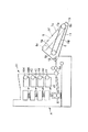
本発明に係る本実施例の画像形成装置の概略構成を図1に示す。尚、本実施例では、画像形成装置は、電子写真方式を利用したカラー画像形成装置Aであり、4色フルカラー画像を形成できるレーザビームプリンタである。そして、現像剤(例えば、トナー)で可視像化された画像を熱等によって転写材に定着させる画像形成工程を経て画像形成を行なう。
Example 1
FIG. 1 shows a schematic configuration of the image forming apparatus of the present embodiment according to the present invention. In this embodiment, the image forming apparatus is a color image forming apparatus A using an electrophotographic system, and is a laser beam printer capable of forming a full-color image of four colors. Then, an image is formed through an image forming process in which an image visualized with a developer (for example, toner) is fixed to a transfer material by heat or the like.
カラー画像形成装置Aは、形成する色(イエロー、マゼンタ、シアン、ブラック)毎に、第1の像担持体としてドラム型の電子写真感光体である、感光ドラム1(1Y、1M、1C、1BK)を備えている。尚、それぞれの感光ドラム1は駆動手段(図示せず)によって、例えば図1では反時計周りに回転駆動されるようになっている。 The color image forming apparatus A is a photosensitive drum 1 (1Y, 1M, 1C, 1BK) that is a drum-type electrophotographic photosensitive member as a first image carrier for each color (yellow, magenta, cyan, black) to be formed. ). Each photosensitive drum 1 is rotated by a driving means (not shown), for example, counterclockwise in FIG.
感光ドラム1の回転方向に沿ってその周囲に、画像形成手段として、帯電工程にて感光ドラム1の表面を均一に帯電させる帯電手段である帯電装置2(2Y、2M、2C、2BK)、潜像形成工程(露光工程)にて画像情報に基づいて光源(例えば、レーザ光やLED光)を点滅させ、感光ドラム1上に静電潜像を形成する潜像形成手段(露光手段)である露光装置3(3Y、3M、3C、3BK)、現像工程にて感光ドラム1上の静電潜像に現像剤であるトナーを付着させて可視像化(現像)して現像剤像(トナー像)を形成する現像手段である現像装置4(4Y、4M、4C、4BK)、転写工程にて感光ドラム1上のトナー像が転写される第二の像担持体としての中間転写体5aを含む中間転写部(中間転写ユニット)5等が設置されている。そして、この中間転写ユニット5を構成する中間転写体5aはベルト形状であり、時計回りに回転している。
A charging device 2 (2Y, 2M, 2C, 2BK), which is a charging unit that uniformly charges the surface of the photosensitive drum 1 in the charging process as an image forming unit around the photosensitive drum 1 in the rotation direction. A latent image forming unit (exposure unit) that forms a static latent image on the photosensitive drum 1 by blinking a light source (for example, laser light or LED light) based on image information in an image forming step (exposure step). In the exposure device 3 (3Y, 3M, 3C, 3BK), a developer image (toner) is visualized (developed) by attaching toner as a developer to the electrostatic latent image on the photosensitive drum 1 in the developing process. A developing device 4 (4Y, 4M, 4C, 4BK) that is a developing means for forming an image), and an
ここで、感光ドラム1と帯電装置2と現像装置4等の画像形成手段は、それぞれの色毎に一体化されて画像形成部S(SY、SM、SC、SBK)を構成している。そして、この画像形成部Sは、中間転写ユニット5に対して、鉛直方向で並列に固定配置されている。感光ドラム1上の静電潜像を現像する現像装置4は、それぞれの色毎にトナーを収容する現像剤収容部41を有している。各現像剤収容部41には、表面に現像剤であるトナーを担持するとともに、感光ドラム1と対向し、現像剤収容部41から感光ドラム1へとトナーを移動させる現像剤担持体である現像剤担持ローラ42が設けられており、現像剤担持ローラ42により感光ドラム1上の静電潜像を現像できるようになっている。
Here, the image forming means such as the photosensitive drum 1, the charging device 2, and the developing device 4 are integrated for each color to form an image forming unit S (SY, SM, SC, SBK). The image forming unit S is fixedly arranged in parallel to the
各色の感光ドラム1上のトナー像を、対向した中間転写体5aに各色順次転写、重ね合わせることにより、中間転写体5a上に静電吸着されたひとつのフルカラートナー像が形成される。尚、感光ドラム1から中間転写体5aにトナーを転写させるために、各感光ドラム1に対向させて電気バイアスを発生させる転写手段5d(5dY、5dM、5dC、5dBK)を、ベルトである中間転写体5aを挟んで感光ドラム1の反対側に設けている。
By sequentially transferring and superimposing the toner images on the photosensitive drums 1 for the respective colors onto the
中間転写体5a上にひとつのトナー像を形成した後、中間転写体5aはトナー像を担持し、転写材Pへの転写部Eまで更に回転する。一方、転写材収納箱6内の転写材Pは、給搬送装置7によって所定のタイミングで転写場所Eへ供給される。この転写場所Eには、転写ベルト5aに対して電気バイアスを発生させる転写手段5eを、転写材Pの搬送路を挟んで中間転写体5aの反対側に設けている。
After forming one toner image on the
このように静電吸着力を利用して、トナー像を転写材Pに転写させる。更に、定着工程にて転写材Pへトナー像を固定化させるために、転写材Pは定着手段である定着装置8へと搬送される。定着装置8では熱・圧力などを利用して、転写材P上のトナーを溶融・定着させる。
In this way, the toner image is transferred to the transfer material P using the electrostatic attraction force. Further, in order to fix the toner image to the transfer material P in the fixing process, the transfer material P is conveyed to a
定着装置8を通過した転写材Pは搬送ユニット9により、排紙トレイ10に排出される。尚、転写材Pは定着装置8〜排紙トレイ10まで底面から上面へと曲線である搬送経路20に沿って搬送される。
The transfer material P that has passed through the fixing
ところで、従来例にて説明したように、複数の画像形成部Sを有するカラー画像形成装置においては、それぞれの画像形成部Sに設けられた現像装置4において、現像剤補給、現像装置の交換、そして、搬送経路に滞留した転写材Pの除去、又は中間転写体5aの交換、等のカラー画像形成装置のメンテナンスを行なうために、開閉部材(アクセスドア)を設けなければならないが、そのため、従来例では、ある装置構成要素をメンテナンスするために、メンテナンスする必要の無い構成要素を装置から外さなければならない、という煩わしさがあった。又、メンテナンスの対象となるそれぞれの手段毎に、アクセスするためのドアを複数設けなければならないことが多かった。
By the way, as described in the conventional example, in a color image forming apparatus having a plurality of image forming units S, in the developing device 4 provided in each image forming unit S, replenishment of developer, replacement of the developing device, An open / close member (access door) must be provided in order to perform maintenance of the color image forming apparatus such as removal of the transfer material P staying in the conveyance path or replacement of the
そこで、本発明においては、使用者の簡単な操作によって、カラー画像形成装置のメンテナンスを行なうことができるようにした。 Therefore, in the present invention, the color image forming apparatus can be maintained by a simple operation of the user.
本発明の本実施例1は図1に示される構成の上記に説明した画像形成装置において実施される。上記に説明したように、画像形成部は鉛直方向に配列され、中間転写体5aが各画像形成部Sの一次転写部に沿って、各色のトナー像の一次転写が行われるベルト面Taを鉛直方向に形成しており、ベルト面Taは下方から上方へと移動するようにされる。そして、図2に示されるように、アクセスドア11は側面鉛直方向に設けられ、断面でその下端の支点12を回動中心とし、ベルト面Taと同じ方向に設置された状態(図2(a))から回動し、ドア11上端13が下方へ向かうようにして開けられている(図2(b))。
The first embodiment of the present invention is implemented in the above-described image forming apparatus having the configuration shown in FIG. As described above, the image forming units are arranged in the vertical direction, and the
尚、このアクセスドア11の開動作を行う時、画像形成時における中間転写体5aから転写材Pへ画像転写される箇所の前後での転写材移動軌跡方向で形成される面と略平行で同じ方向に開閉部材が回動するのがよい。なぜなら、まず画像形成装置において中間転写体5aは転写材搬送路に接していなければならない。使用者の装置内メンテナンスとして、転写材搬送路中の転写材ジャム処理がある。従って、搬送路に近接配置している中間転写体5aを移動させる必要がある。
When the
ここで、本発明の特徴として、アクセスドア11と画像形成装置の内部構成との関係において、感光ドラム1と中間転写体ユニット5とは、その境界で分割され、分割された中間転写体ユニット5部分がアクセスドア11に保持されていることが挙げられる。そのため、使用者はひとつのドアを開ける動作のみを行うことで、以下に挙げるメンテナンス操作に移行することができる。
Here, as a feature of the present invention, in the relationship between the
(1)転写材Pの搬送経路20のうち、転写材収納部6〜中間転写体5aから転写材Pへの画像転写部E〜定着装置8までの間で転写材Pのジャムが起こったとする。この場合、アクセスドア11をひとつ開くことによって、搬送経路20全てに対して使用者の視認性が確保されている。よって、使用者はジャム処理を容易に行なうことができる。
(1) In the
(2)図3に示すように、画像形成部Sを構成する部品、特に現像装置4及び感光ドラム1いずれの対も、他の構成部品に干渉することなく脱着可能である。 (2) As shown in FIG. 3, the parts constituting the image forming unit S, in particular, any pair of the developing device 4 and the photosensitive drum 1 can be attached and detached without interfering with other constituent parts.
(3)図4に示すように、アクセスドア11を開けた状態では、中間転写体ユニット5がアクセスドア11と共に露出されているので、アクセスドア11を開くことによって、中間転写ユニット5の脱着に干渉する構成部品はなく、使用者の視界にあるので、視認性が良く、容易に、中間転写ユニット5又は中間転写体5a等の中間転写ユニット5に関連する部品を交換することが可能である。
(3) As shown in FIG. 4, when the
ここで、図5に示されるように、アクセスドア11の開閉状態によって、中間転写ユニット5とドア11の相対位置が異なると好適である。即ち、中間転写ユニット5とドア11の相対位置において、ドア11が開いていない普通状態(図2(a))では、転写面Taが全ての画像形成部Sに接触している状態であるが、ドア11が開いても変化しない状態の中間転写ユニット5の位置5fから、ずらして位置5gに移動させることを可能とする。ここでは、普通状態(図2(a))で上側の中間転写体5aのローラ5b(例えばテンションローラを兼ねる)を支点として中間転写ユニット5が回動するようになっている。このような場合、ドア11の動きによって、ドア11に対する中間転写ユニット5の相対位置を変化させることができ、そのことで、装置内部視認範囲を拡大し、使用者にとって画像形成装置のメンテナンス性を更に向上させることができる。これによって、中間転写ユニット5の動きをドア11の回動軌跡と異なるものにすることができ、中間転写ユニット5における視界が広がる。尚、図2〜図5においては、便宜上中間転写ユニット5において2つのローラ5b、5cに中間転写体5aを巻架させた構成を図示しているが、図1のよう3つのテンションローラ5b、5cにて巻架されている場合も同様であり、下方の2つのローラ5cのうちいずれかをドア11において移動する支点としてもよい。このように、画像形成装置Aの構成によって適宜調整する。
Here, as shown in FIG. 5, it is preferable that the relative positions of the
又、別の方法として、中間転写ユニット5の自重によって相対位置を変化させることができる。例えば、中間転写ユニット5の上部のみをドア11に支持し、ドアを開けていくに従って、支持軸と中間転写ユニット5重心のズレが大きくなり、中間転写ユニット5は次第に傾いていく。この傾きを利用して、中間転写ユニット5が使用者に対して取り出しやすいような状態にドア11に保持された中間転写ユニット5の位置が下方に下がっていくように設定させればよい。つまり、アクセスドア11が開閉移動を行う時、中間転写ユニット5の移動量がアクセスドア11の移動量よりも大きくなる。
As another method, the relative position can be changed by the weight of the
その例として,中間転写ユニット5がローラ5b付近でアクセスドア11に保持されている。またローラ5c付近はアクセスドア11とは移動していかない,例えば画像形成装置の枠などに付いているレバー(図示せず)などで中間転写ユニット5を押し付けている構成をとる。アクセスドア11が閉まっている時はレバーによって中間転写ユニット5は画像形成位置にとどまることができる。アクセスドアが開く動作がきっかけとなって,レバーが中間転写ユニット5への押圧をやめるようにすれば,アクセスドア11が開いた状態での中間転写ユニット5はローラ5b付近で保持されて宙吊りの形になるので,例えば,ローラ5c付近は重力によって下がるのである。
As an example, the
ドア11に中間転写ユニット5が保持されていることで、自然状態では、ドア11の開閉に連動して中間転写ユニット5の移動速度が一定になってしまう。上記のような、中間転写ユニット5のドア11への設置状態を変更する等の方法で、ドア11と中間転写ユニット5の相対速度を一定にしないことで、ドア11の開閉動作中にいろいろな機能を盛り込むことができる。例えば,ドア11の開閉動作を利用して、中間転写ユニット5への回転駆動連結を脱着したり、中間転写ユニット5と他の内部構成部品との干渉を回避することが可能となる。
Since the
又、中間転写ユニット5において、中間転写体5aの駆動源が、設けられた画像形成部S、ここでは4つの画像形成部Sのうち少なくともひとつの画像形成部Sにおける像担持体である感光ドラム1の駆動源と同一であれば、回転同期を簡単に取ることができ、回転同期がとれれば、画像転写における劣化を防ぐことができる。例えば、ブラック画像形成部SBKにおける感光ドラム1BKと中間転写体5aの回転駆動源を共通にすると、ブラック形成画像の転写性は格段に向上する。更に、ブラックだけでなく、イエロー感光ドラム1Y、マゼンタ感光ドラム1M、シアン感光ドラム1Cも同一駆動源により、同期を取れば、色重ね合わせに関しても画像再現性が向上する。
In the
しかし、中間転写体5aと感光ドラム1のいずれかが同一駆動源であり、且つ、ドア11を開けることで中間転写体5aが移動するならば、中間転写体5aもしくは感光ドラム1の駆動経路途中に、駆動着脱機構が必要となる。本実施例のように、画像形成部Sを鉛直に配置した場合は、一般的にベルト状中間転写体5aが、鉛直方向に配列した2つのテンションローラ5bと5cとの間に張られている側に画像形成部Sを配置した方が、感光ドラム1から中間転写体5aへの画像転写性は良い。図1の構成の場合、普通状態における中間転写ユニット5の上側のローラ5bがベルト駆動を担うことが多い。そして、ドア11が開くのと連動して中間転写体5aの駆動着脱機構を働かせば、容易に中間転写ユニット5を移動させることができる。
However, if either the
尚、本実施例にて、画像形成部Sを鉛直方向に配置した理由は、図9や図12のような複数の画像形成部Sを水平方向に並列配置している画像形成装置では、装置の設置面積が大きくなってしまい、設置場所が限定されたり、装置のメンテナンス等をする際に利用者が回りこまなければアクセスできないなど、結果として不便さを感じさせることがあったからである。しかし、画像形成部Sを水平配置しているものにおいても、中間転写ユニット5を上方に設置し、上方のアクセスドアに中間転写ユニット5を保持させることで、本発明は適用可能である。
In the present embodiment, the reason why the image forming unit S is arranged in the vertical direction is that, in the image forming apparatus in which a plurality of image forming units S as shown in FIGS. As a result, the installation area is limited, the installation location is limited, and the user cannot access unless the user goes around when performing maintenance of the apparatus. However, even in the case where the image forming unit S is horizontally arranged, the present invention can be applied by installing the
又、中間転写体5aから転写材Pへのトナー像の転写が行なわれる第1の位置(転写部)Eに対して、転写部Eを通過した後の転写材搬送方向角度が通過前の転写材搬送角度に対して上45°よりも浅い角度であると好適である。その理由・構成は以下に述べる。
Further, the transfer material conveyance direction angle after passing through the transfer portion E with respect to the first position (transfer portion) E where the toner image is transferred from the
転写材Pへ転写した後、中間転写体5aは再び新しい画像を感光ドラム1から転写・保持しなければならない。一方、中間転写体5a上のトナーが転写材へ100%転写されることはなく、転写残トナーとしてそのまま中間転写体5a上に付着している場合がある。そしてそのまま感光ドラム1との転写箇所までトナーが付着していると、新しい画像と重なって画像品質が劣化してしまう。この画像劣化を防ぐために、中間転写体5aの経路上で転写材Pへの転写箇所と感光ドラム1との転写箇所の間に、中間転写体5a用の清掃部材5hを配置しなければならないことがある。
After the transfer to the transfer material P, the
又、転写材への転写箇所前後で転写材搬送方向角度が45°以下という条件で、良好な画像が得られる。更に、清掃部材5hを転写材搬送方向角度45°以上のところに配置した場合、もしも転写材Pの傾きが45°以上になった場合、転写材P上のトナー未定着画像が清掃部材5hにこすれてしまう恐れがある。
Further, a good image can be obtained under the condition that the transfer material conveyance direction angle is 45 ° or less before and after the transfer portion to the transfer material. Further, when the cleaning
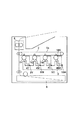
参考例
図6、図7に本発明の参考例を示す。図6は、中間転写ユニット5におけるテンションローラ5b、5cの数以外は図1におけるカラー画像形成装置同構成の画像形成装置である本参考例の画像形成装置Bの斜視図であり、便宜上、内部断面を装置側面方向から図示する。内部構成は実施例1と同構成である。本参考例では、図7に示すように、アクセスドア11aは鉛直方向を軸として水平方向に回動して開いている。この場合,左右どちらに開いても、得られる効果は同じである。
Reference Example FIGS. 6 and 7 show a reference example of the present invention. FIG. 6 is a perspective view of an image forming apparatus B of this reference example which is an image forming apparatus having the same configuration as that of the color image forming apparatus in FIG. 1 except for the number of
本参考例においても、ドア11aに中間転写ユニット5が支持されており、ドア11aを開くことで、中間転写ユニット5、感光ドラム1及び現像装置4等を有する画像形成部S、転写材搬送経路20ともに使用者からの視認性は充分に確保される。
Also in this reference example , the
以上、実施例1を用いて説明したように、本発明によれば、カラー画像形成装置の内部構成要素に対して、アクセスドアの分割点を静電潜像から現像化させた画像を担持する像担持体と中間転写体の接触部にし、アクセスドア側に中間転写体を保持させことで、少なくともひとつのドアを設けることにより、現像剤補給もしくは現像装置交換、転写材除去処理、中間転写体調整等のメンテナンスを行なうことが可能となる。 As described above with reference to Example 1, according to the present invention, with respect to internal components of a color image forming apparatus, for carrying an image obtained by developing the division point of the access door from the electrostatic latent image By providing at least one door by holding the intermediate transfer member on the access door side at the contact portion between the image carrier and the intermediate transfer member, developer replenishment or development device replacement, transfer material removal processing, intermediate transfer member Maintenance such as adjustment can be performed.
又、このドア構成において、転写材搬送と同じ方向からアクセスできるので、ひとつのアクセスドアを開ければ、現像装置、中間転写体及び転写材搬送部が露出されることになる。そして、前述した部分全てを使用者の視界に入れることができ、その構成要素に直にアクセス可能となる。 Further, in this door configuration, since it can be accessed from the same direction as the transfer material conveyance, if one access door is opened, the developing device, the intermediate transfer member, and the transfer material conveyance unit are exposed. And all the above-mentioned parts can be put into a user's view, and the component can be accessed directly.
1(1Y、1M、1C、1BK) 感光ドラム(像担持体)
4(4Y、4M、4C、4BK) 現像装置(画像形成手段)
5 中間転写ユニット(中間転写部)
5a 中間転写体
11、11a アクセスドア(開閉部材)
20 転写材搬送経路
P 転写材
S(SY、SM、SC、SBK) 画像形成部
E 転写部
1 (1Y, 1M, 1C, 1BK) Photosensitive drum (image carrier)
4 (4Y, 4M, 4C, 4BK) Developing device (image forming means)
5 Intermediate transfer unit (intermediate transfer unit)
5a
20 Transfer material transport path P Transfer material S (SY, SM, SC, SBK) Image forming portion E Transfer portion
Claims (1)
前記中間転写体は、前記開閉部材の開放動作時、前記開閉部材のみに保持され、前記開閉部材の前記回動中心周りの回動による開放動作と共に移動するものであり、且つ、前記開閉部材の開放状態では、前記中間転写体は前記開閉部材に対して脱着可能であり、
前記中間転写体は、前記開閉部材の上端側であって前記中間転写体の一端に回動中心を有し、前記開閉部材の開放状態では、前記開閉部材に対して前記中間転写体の回動中心周りに回動することによって前記中間転写体の回動中心とは反対側の他端が下方に移動可能であることを特徴とする画像形成装置。 A plurality of image carriers on which images are formed, an intermediate transfer member to which images formed on the plurality of image carriers are transferred, and an opening / closing member that can be opened and closed with respect to the apparatus body, In the image forming apparatus having a rotation center at the lower end of the opening / closing member,
The intermediate transfer member is held only by the opening / closing member during the opening operation of the opening / closing member, and moves together with the opening operation by rotation around the rotation center of the opening / closing member, in the open state, the intermediate transfer body Ri detachable der respect to the closing member,
The intermediate transfer member has a rotation center at one end of the intermediate transfer member on the upper end side of the opening / closing member, and the intermediate transfer member rotates with respect to the opening / closing member in the open state of the opening / closing member. An image forming apparatus , wherein the other end of the intermediate transfer member opposite to the center of rotation is movable downward by rotating around the center .
Priority Applications (1)
| Application Number | Priority Date | Filing Date | Title |
|---|---|---|---|
| JP2003373593A JP4323927B2 (en) | 2003-10-31 | 2003-10-31 | Image forming apparatus |
Applications Claiming Priority (1)
| Application Number | Priority Date | Filing Date | Title |
|---|---|---|---|
| JP2003373593A JP4323927B2 (en) | 2003-10-31 | 2003-10-31 | Image forming apparatus |
Publications (3)
| Publication Number | Publication Date |
|---|---|
| JP2005134831A JP2005134831A (en) | 2005-05-26 |
| JP2005134831A5 JP2005134831A5 (en) | 2006-12-14 |
| JP4323927B2 true JP4323927B2 (en) | 2009-09-02 |
Family
ID=34649576
Family Applications (1)
| Application Number | Title | Priority Date | Filing Date |
|---|---|---|---|
| JP2003373593A Expired - Fee Related JP4323927B2 (en) | 2003-10-31 | 2003-10-31 | Image forming apparatus |
Country Status (1)
| Country | Link |
|---|---|
| JP (1) | JP4323927B2 (en) |
Families Citing this family (2)
| Publication number | Priority date | Publication date | Assignee | Title |
|---|---|---|---|---|
| JP4725308B2 (en) | 2005-11-30 | 2011-07-13 | ブラザー工業株式会社 | Image forming apparatus |
| US20120237257A1 (en) * | 2011-03-18 | 2012-09-20 | Konica Minolta Business Technologies, Inc. | Color image forming apparatus |
-
2003
- 2003-10-31 JP JP2003373593A patent/JP4323927B2/en not_active Expired - Fee Related
Also Published As
| Publication number | Publication date |
|---|---|
| JP2005134831A (en) | 2005-05-26 |
Similar Documents
| Publication | Publication Date | Title |
|---|---|---|
| JP5127565B2 (en) | Cartridge and image forming apparatus | |
| JP4717455B2 (en) | Image forming apparatus | |
| JP6094869B2 (en) | Image forming apparatus | |
| EP2950163B1 (en) | Image forming apparatus | |
| JP2007164128A (en) | Image forming apparatus | |
| US9134641B2 (en) | Image forming apparatus | |
| US10474063B2 (en) | Image forming apparatus having movable shutter member | |
| JP6210693B2 (en) | Image forming apparatus | |
| JP7362381B2 (en) | Image forming device | |
| JP2006145801A (en) | Image forming apparatus | |
| JP2016161714A (en) | Developing device, process cartridge, and image forming apparatus | |
| JP4323927B2 (en) | Image forming apparatus | |
| JP2018077458A (en) | Development container, process cartridge and image formation apparatus | |
| JP2005156776A (en) | Color image forming apparatus | |
| JP2011095522A (en) | Image forming apparatus | |
| JP2006106134A (en) | Image forming apparatus | |
| JP4422974B2 (en) | Image forming apparatus | |
| JP2004145060A (en) | Color image forming apparatus | |
| JPH10115961A (en) | Image forming device | |
| JP4343658B2 (en) | Color image forming apparatus | |
| JP2004177525A (en) | Image forming apparatus and process cartridge | |
| JPH06138744A (en) | Color image forming device | |
| JP2003122078A (en) | Image forming apparatus | |
| JP6132197B2 (en) | Image forming apparatus | |
| JP2005331877A (en) | Image forming apparatus |
Legal Events
| Date | Code | Title | Description |
|---|---|---|---|
| A521 | Request for written amendment filed |
Free format text: JAPANESE INTERMEDIATE CODE: A523 Effective date: 20061025 |
|
| A621 | Written request for application examination |
Free format text: JAPANESE INTERMEDIATE CODE: A621 Effective date: 20061025 |
|
| A977 | Report on retrieval |
Free format text: JAPANESE INTERMEDIATE CODE: A971007 Effective date: 20080918 |
|
| A131 | Notification of reasons for refusal |
Free format text: JAPANESE INTERMEDIATE CODE: A131 Effective date: 20081118 |
|
| A521 | Request for written amendment filed |
Free format text: JAPANESE INTERMEDIATE CODE: A523 Effective date: 20090119 |
|
| A131 | Notification of reasons for refusal |
Free format text: JAPANESE INTERMEDIATE CODE: A131 Effective date: 20090224 |
|
| A521 | Request for written amendment filed |
Free format text: JAPANESE INTERMEDIATE CODE: A523 Effective date: 20090427 |
|
| TRDD | Decision of grant or rejection written | ||
| A01 | Written decision to grant a patent or to grant a registration (utility model) |
Free format text: JAPANESE INTERMEDIATE CODE: A01 Effective date: 20090519 |
|
| A01 | Written decision to grant a patent or to grant a registration (utility model) |
Free format text: JAPANESE INTERMEDIATE CODE: A01 |
|
| A61 | First payment of annual fees (during grant procedure) |
Free format text: JAPANESE INTERMEDIATE CODE: A61 Effective date: 20090605 |
|
| R150 | Certificate of patent or registration of utility model |
Free format text: JAPANESE INTERMEDIATE CODE: R150 |
|
| FPAY | Renewal fee payment (event date is renewal date of database) |
Free format text: PAYMENT UNTIL: 20120612 Year of fee payment: 3 |
|
| FPAY | Renewal fee payment (event date is renewal date of database) |
Free format text: PAYMENT UNTIL: 20120612 Year of fee payment: 3 |
|
| FPAY | Renewal fee payment (event date is renewal date of database) |
Free format text: PAYMENT UNTIL: 20130612 Year of fee payment: 4 |
|
| LAPS | Cancellation because of no payment of annual fees |