JP4322322B2 - Ultrasonic therapy device - Google Patents
Ultrasonic therapy device Download PDFInfo
- Publication number
- JP4322322B2 JP4322322B2 JP05955698A JP5955698A JP4322322B2 JP 4322322 B2 JP4322322 B2 JP 4322322B2 JP 05955698 A JP05955698 A JP 05955698A JP 5955698 A JP5955698 A JP 5955698A JP 4322322 B2 JP4322322 B2 JP 4322322B2
- Authority
- JP
- Japan
- Prior art keywords
- treatment
- ultrasonic
- ultrasound
- ultrasonic therapy
- therapy apparatus
- Prior art date
- Legal status (The legal status is an assumption and is not a legal conclusion. Google has not performed a legal analysis and makes no representation as to the accuracy of the status listed.)
- Expired - Fee Related
Links
- AWYMFBJJKFTCFO-UHFFFAOYSA-N C(C1)C2C1CCC2 Chemical compound C(C1)C2C1CCC2 AWYMFBJJKFTCFO-UHFFFAOYSA-N 0.000 description 1
Images


Classifications
-
- A—HUMAN NECESSITIES
- A61—MEDICAL OR VETERINARY SCIENCE; HYGIENE
- A61N—ELECTROTHERAPY; MAGNETOTHERAPY; RADIATION THERAPY; ULTRASOUND THERAPY
- A61N7/00—Ultrasound therapy
Landscapes
- Health & Medical Sciences (AREA)
- Engineering & Computer Science (AREA)
- Biomedical Technology (AREA)
- Nuclear Medicine, Radiotherapy & Molecular Imaging (AREA)
- Radiology & Medical Imaging (AREA)
- Life Sciences & Earth Sciences (AREA)
- Animal Behavior & Ethology (AREA)
- General Health & Medical Sciences (AREA)
- Public Health (AREA)
- Veterinary Medicine (AREA)
- Surgical Instruments (AREA)
Description
【0001】
【発明の属する技術分野】
本発明は、超音波により生体内の結石を破砕し、また癌等の腫瘍を焼灼する超音波治療装置に関する。
【0002】
【従来の技術】
近年、MIT(Minimally Invasive Teratment)とよばれる最少侵襲治療の流れが医療の各分野で注目を集めている。一例としては、結石症の治療に体外から強力超音波を照射し、無侵襲的に結石を破砕治療する結石破砕装置の実用化が挙げられ、泌尿器系結石の治療法を大きく様変わりさせた。この結石破砕装置に使用される強力超音波発生源としては、水中放電方式・電磁誘導方式・微小爆発方式・ピエゾ方式等があり、特にピエゾ方式では強力超音波の圧力が小さいという短所はあるが、小焦点で、消耗品がなく、強力超音波圧力を任意にコントロールでき、複数のピエゾ素子にかかる駆動電圧を位相制御することで焦点位置を任意にコントロールできる等、優れた長所がある。
【0003】
一方、癌治療の分野でもMITは1つのキーワードとなっており、特に癌の場合、その治療の多くを外科的手術に頼っている現状から、本来その臓器が持つ機能や外見上の形態を大きく損なう場合が極めて多く、生命を長らえたとしても患者にとって大きな負担が残る。このため、患者のQOL.(Quality of Life)を考慮した侵襲の少ない治療法及びそのための装置の開発が強く望まれている。
【0004】
このような流れの中、悪性新生物、いわゆる癌の治療技術のーつとして、ハイパーサーミア療法が注目されるようになってきた。これは、腫瘍組織と正常組織の熱感受性の違いを利用して、患部を42.5〜43゜C程度に加温・維持することで癌細胞のみを選択的に死減させる治療法である。加温の方法としてはマイクロ波等の電磁波を用いる方法が先行しているが、この方法では生体の電気的特性により深部の腫瘍を選択的に加温することは困難であり、深さ5cm以上の腫瘍に対しては良好な治療成績は望めない。そこで、深部腫瘍の治療には集束性が良く深達度の高い超音波エネルギーを利用する方法が考えられる。
【0005】
また、上記加温治療法を更に進めて、ピエゾ素子より発生した強力超音波を患部に鋭く集束させて腫瘍部分を80゜C以上に加熟し、腫瘍組織を瞬時に熱変性壊死させるような治療法も考えられている。
【0006】
この治療法では、従来のハイパーサーミアとは異なり、焦点近傍の限局した領域に非常に強い強度(数百〜数千W/cm2 )の超音波が投入されるため、焦点近傍の狭い領域のみが瞬時に熱変性壊死させられる。かつ、その小さな焦点を正確に位置決めしながら患部領域全体を焼灼する必要があるため、焦点の位置決め技術が非常に重要となる。
【0007】
これに関する1つの解決法として、MRIの化学シフトを利用した体内非侵襲温度分布画像化により術中の発熱点を計測する技術が開示されている。更に、超音波単独のシステムについても、治療用超音波の焦点領域からの反射波を検出して超音波画像上に表示する手法が開示されている。
【0008】
従来の、特に単純なBモード断層画像を術中モニタとして使用するタイプの超音波治療装置においては、Bモード断層画像1画面だけでは腫瘍の全容を一時に把握できないため、設定焼灼領域を設定しても設定位置や範囲が実際の患部とずれて設定される場合が生じる。従って、このまま照射を行うと腫瘍の撃ち残しが出るばかりでなく、周囲の正常組織を無駄に傷つけてしまう可能性があった。
【0009】
また、従来の超音波治療装置では「治療用超音波の入射経路が周囲臓器にどの程度掛かっているか」「このまま照射を行って安全か」等を事前に簡便かつリアルタイムに確認する手段が無かったため術前の治療計画に従うしかなく、実際の臓器の移動や治療用超音波入射経路の違いに応じた修正がきかなかった。このため、実際の照射の際に超音波通過領域に重要臓器が掛かってしまい、誤って副作用を生じてしまったり、移動の際にアプリケータが他の部位にあたって狙ったところを照射できなくなってしまう虞があった。
【0010】
更に、MRI(磁気共鳴診断装置)等の診断装置を術中モニタリング画像として用いた場合には3次元的な画像データ取得が可能であるため、治療用超音波の通過領域に他の重要臓器が掛からないように制御することは可能である。しかし、これらの見積もりはあくまでも仮想であり、「実際の照射位置からの強力超音波エネルギー入射時の通過経路への影響」、「呼吸移動等による周囲臓器との位置関係の変化とその影響」、「実際に照射する位置にアプリケータが移動した際にアプリケータが他の部位にあたって邪魔にならないか」、などを簡便に判別することは出来なかった。
【0011】
【発明が解決しようとする課題】
本発明の目的は、治療用超音波を従来よりも安全かつ確実に照射できる超音波治療装置を提供することにある。
【0012】
【課題を解決するための手段】
本発明は、患部を治療するために、治療用超音波を患部に集束する超音波治療装置において、治療用超音波発生源と超音波プローブとを有しているアプリケータと、前記アプリケータを移動する機構と、前記治療用超音波発生源から治療用超音波を発生させるために前記治療用超音波発生源を駆動するドライバと、前記超音波プローブを駆動して前記治療用超音波の焦点付近を超音波でスキャンし、得られたエコーに基づいて断層像を生成し、表示する診断装置と、前記患部を含むように治療領域を設定するためのコンソールと、治療シミュレーションを実行するシステムコントローラとを具備し、前記治療シミュレーション中には、前記機構は前記治療領域に従ってデザインされた前記焦点の移動コースに従って前記アプリケータを移動し、前記ドライバは前記治療用超音波を発生させないために前記治療用超音波発生源を駆動せず、前記診断装置は前記超音波プローブを介して前記焦点付近をスキャンして、前記断層像と一緒に前記焦点を表す焦点マーカを表示するものである。
(作用)患部が治療用超音波の焦点よりも大きいとき、患部を含むように治療領域が設定される。そして、治療用超音波の焦点は、この治療領域に基づいてデザインされた移動コースに従って移動される。これにより、焦点より大きな患部の全体が治療され得る。本発明では、実際に治療する、つまり治療用超音波を照射する前に、治療が良好に行われるか否かを、シミュレーションにより確認することができる。このシミュレーションでは、アプリケータは、治療領域に基づいてデザインされた移動コースに従って移動される。この移動中には、超音波プローブにより患者の体内は継続的にスキャンされイメージングされるが、治療用超音波は発生されない。そして、得られた断層像は、焦点を表す焦点マーカと一緒に表示される。このように、アプリケータを、実際のコースに沿って動かして、患部と焦点との位置関係を観察することにより、治療領域が患部に対して正しくセットされているか否かを正確に確認することができる。
【0013】
【発明の実施の形態】
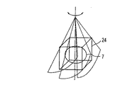
以下、図面を参照して、本発明を好ましい実施形態により説明する。図1には、本実施形態による超音波治療装置の構成を示している。アプリケータ1のフレーム27には、治療用超音波発生源2が取り付けられている。治療用超音波発生源2には、強力な超音波を発生するピエゾ素子又はピエゾ素子群が、球の一部分の形状に形成又はアレイされている。この治療用超音波発生源2の中心軸CL上であって、球半径の深さの点、つまり球の中心において、ピエゾ素子から発生した治療用超音波が集束するようになっている。この集束点を中心として、一定レベル以上のエネルギーを示す領域を、一般的に、焦点8と称している。この焦点8は、例えば、径10mm、長さ15mmの縦長形状を有している。
【0014】
このフレーム27及び治療用超音波発生源2の略中心部分には孔が開けられており、この孔に円柱形状の超音波プローブ16が、その軸が発生源2の中心軸CLに揃う状態で、且つ軸方向に前後に移動自在に挿入されている。治療用超音波発生源2に対する超音波プローブ16の突出量を検出するために、エンコーダ23が設けられている。このように発生源2に対して超音波プローブ16が設けられているので、発生源2の焦点8は、超音波プローブ16により得られる断層像では、その中心線上に存在するし、その深さはエンコーダ23により検出された突出量に基づいて計算することができるようになっている。
【0015】
この超音波プローブ16を介して焦点8の付近を超音波で走査して、断層像を生成し、これをディジタルスキャンコンバータ(DSC)18を介してCRT19に表示するために、超音波診断装置17が設けられている。なお、システムコントローラ9の機能により、CRT19に表示された断層像には、焦点を表す焦点マーカや、コンソールパネル10を介して設定された焼灼領域(治療領域)を表す図形マーカがスーパーインポーズされて、CRT19に表示されるようになっている。
【0016】
治療用超音波発生源2及び超音波プローブ16の下側には、治療用超音波やイメージング用の超音波を損失少なく患者に導くと共に、患者からの反射波を損失少なく超音波プローブ16に導くための脱気水等のカップリング液4がカップリング膜5に充填されている。
【0017】
アプリケータ1は、そのフレーム27において、ステージ21から伸びたアーム22の先端に取り付けられており、ステージ21の移動に対応して自由に移動し、また任意の姿勢で静止できるようになっている。このアーム22の動きは、システムコントローラ9の制御下にあるステージコントローラ20により完全に制御されている。
【0018】
治療時には、まず患者を寝台(図示せず)に載置して所定位置に固定する。そしてアプリケータ1のカップリング膜5を、図示しない超音波ゼリー等を塗布した患者体表に接触させる。そして、システムコントローラ9からの制御信号に従って連続波発生回路11又はパルス波発生回路12から切替スイッチ13を介して超音波域の高周波信号がRFアンプ14に供給される。RFアンプ14で増幅された高周波信号は、インピーダンスマッチング回路15を介して治療用超音波発生源2のピエゾ素子に供給される。これにより、ピエゾ素子は機械的に振動して、超音波を発生する。この超音波は、カップリング液4を介して患者体内に導かれ、焦点8を形成し、この焦点8にある患部(腫瘍又は結石)を治療(加温又は破砕)する。
【0019】
図2には、本実施形態による治療計画の立案の手順を示している。ここでは癌等の腫瘍を超音波で焼灼する場合で説明する。ここで、患部7が焦点8より大きいとき、患部7の全体を治療するには、焦点8を移動しながら、治療用超音波の照射を繰り返すという動きが必要になる。この焦点8の移動範囲を決定するのが、焼灼領域(治療領域)であり、治療計画の最大の目的は、この焼灼領域を患部に対して正しく、つまり、焼灼領域が過不足無く患部をカバーするように、設定することである。
【0020】
治療計画は、大きく、事前検査と、一次計画と、二次計画とに分けられる。このうち、二次計画が特徴的である。まず、事前検査ST1では、治療用超音波発生源2を駆動せず、治療用超音波を発生せず、超音波プローブ16を使って断層像により患者の体内を観察する。場合によっては、X線CT画像やMRI画像等が参照される。この事前検査ST1により、患部の大体の位置や大きさや形状が確認される。
【0021】
次に、一次計画では、焼灼領域がラフに設定される。このためにアプリケータ1を、事前計画ST1で確認した患部の近くの体表に当て(ST2)、超音波プローブ16を介して患部を立体的にイメージングする(ST3)。そして、患部7をカバーするように、焼灼領域を設定する(ST4)。
【0022】
図4(a)には、焼灼領域の設定画面を示している。この画面には、患部像7′と、焦点マーカ8′と、焼灼領域マーカ24′とが表示されている。焼灼領域を設定する一般的な手順は、焦点マーカ8′を患部像7′の中心に位置させると、焦点マーカ8′を中心として焼灼領域マーカ24′が例えば矩形に表示される。そして、患部像7′をカバーするように、この焼灼領域マーカ24′の位置やサイズを調整する。この作業を断層像の位置を変えながら繰り返すことで、焼灼領域がラフに設定される。
【0023】
焼灼領域が設定されると、この設定された焼灼領域に従って焦点8の移動コースがシステムコントローラ9でデザインされる。この移動コースは、正弦波形や渦巻き形等の基本コースのサイズを変更することによりデザインされてもよいし、焼灼領域に応じて自由にデザインするようにしてもよい。
【0024】
なお、焦点マーカ8′は、一般的な形状及びサイズに表示してもよいし、もっと正確な形状及びサイズで表示するようにしてもよい。後者では、治療用超音波の強度分布イメージを参照する。この強度分布イメージとは、実際に発生源2から治療用超音波パルスを発生し、そのエコーを超音波プローブ16で受信し、その受信信号に基づいてBモード像を生成する。Bモード像では、エコー強度の強いところが高輝度で表示される。また、エコー強度はその位置の照射強度を反映している。従って、このBモード像は治療用超音波の強度分布を表すことになる。この強度分布から一定の強度以上を示す領域を焦点8として、抽出することができる。なお、この強度分布イメージングの詳細については、治療用強力超音波を発生する超音波発生源から照射されたバースト波の高調波成分を診断用超音波プローブにより受信/画像化する手法が日本特許番号第1851304号、第1821772号に記載されており、また、カラードップラを応用した手法が特願平7−203576号公報に、また、診断用超音波プローブからは画像取得用超音波の送信を行わずに治療用超音波源から照射された超音波の受信のみを行い、その生体内からの反射波を画像化する手法が特許番号第1765452号に記載されている。
【0025】
次に、二次計画が行われる。二次計画では、図3(a)に示すように、システムコントローラ9の制御に従って、一次計画でデザインされた移動コースに従って、実際にアプリケータ1が移動される(ST6)。このとき、治療用超音波発生源2は駆動されず、治療用超音波は発生されない。また、アプリケータ1が移動コースに従って移動している間、超音波プローブ16及び診断装置17によって焦点付近のイメージングが継続され、図3(b)に示すように、刻々と変遷する画像を観察することができる。もちろん、この断層像と一緒に焦点を表す焦点マーカや焼灼領域マーカが表示される。このような作業を、以下、治療シミュレーションと称する。この治療シミュレーションにより、焼灼領域が患部に対して正しく設定されているか否かを正確に確認できる(ST7)。
【0026】
なお、実際の治療では、アプリケータ1は移動コースに沿って断続的に移動し、これに同期して静止時に治療用超音波を短時間照射するが、このシミュレーションでは、このようなアプリケータ1を断続的に移動するのではなく、連続的に移動し、しかも実際の治療時よりも、高速で移動する。これにより、実際の治療時間よりも、大幅に時間を短縮して、シミュレーションを終わらせることができる。
【0027】
もし、図4(b)に示すように、焼灼領域24が患部7に対して正しく設定されていないときには、コンソールパネル10を介して焼灼領域の中心位置(座標)やサイズや形状が微調整(再設定)される(ST5)。焼灼領域の中心位置の変更は、図5(a)に示すように、マウス等のポインティングデバイスを用いて焼灼領域マーカ24′をドラッグして移動することにより行われる。また、焼灼領域のサイズの変更は、図5(b)に示すように、マウス等のポインティングデバイスを用いて焼灼領域マーカ24′をドラッグして拡大、縮小することにより行われる。
【0028】
焼灼領域の再設定後には、治療シミュレーションST6が行われる。これにより、焼灼領域24が患部7に対して正しく設定されているか否かが再度確認される(ST7)。
【0029】
このST5、ST6、ST7のループは、焼灼領域24が患部7に対して正しく設定されていることが確認できるまで、繰り返される。焼灼領域24が患部7に対して正しく設定されていることが確認できた後には、実際に治療用超音波を照射して患部を治療する治療ステップST8が開始される。治療においては、システムコントローラ9の制御により、最終的に設定された焼灼領域に従ってデザインされた移動コースに沿ってアプリケータ1が移動される。このとき、SW13はC側に切り替えられ、連続波発生回路11からの連続的な高周波信号に従って超音波発生源2が駆動され、被検体に治療用超音波が連続的に患部に照射される。
【0030】
このような治療シミュレーションによると、短時間で焼灼領域が患部に対して正しく設定されているか否かを確認して、必要に応じて微調整することができる。従って、より安全で、確実で、信頼性の高い治療を行うことができる。また、実際にアプリケーション1を動かすことで、アプリケータ1が他の構造物等に干渉するか否かを確認することもできる。
【0031】
次に、上述した治療シミュレーションよりももっと簡易に、焼灼領域が患部に対して正しく設定されているか否かを確認することのできる簡易タイプシミュレーションについて説明する。上述した治療シミュレーションでは、実際の移動コースに従ってアプリケータ1を動かしていたが、簡易タイプシミュレーションでは、いわゆる3次元スキャンを採用している。この3次元スキャンの方法としては、図6(a)に示すような超音波プローブ16を軸回転する方法や、図7に示すような超音波プローブ16をスイング(首振り運動)させる方法や、超音波プローブ16を直線移動させる方法等があり、このいずれを採用してもよい。この3次元スキャンによって得られる図6(b)に示すような画像の変化を観察することにより、焼灼領域が患部に対して正しく設定されているか否かを、短時間のうちに、3次元で比較的正確に確認することができる。この簡易タイプのシミュレーションは、上述の治療シミュレーションと併用してもよい。
【0032】
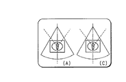
次に、焼灼領域が患部に対して正しく設定されているか否かの確認を容易にするための表示方法について説明する。この表示は、治療シミュレーションや簡易タイプシミュレーションが終了後に、システムコントローラ9により自動的に実行される。治療シミュレーションや簡易タイプシミュレーション中には、複数枚の断層像が生成されている。この複数枚分の断層像データは、フレームメモリ29に保持される。システムコントローラ9は、この複数枚の断層像の中から、上記確認を簡易にのに有用とされる数枚の断層像をピックアップして、一画面に同時表示する。有用とされる数枚の断層像としては、例えば、図3(a)の(A)点、(C)点で得た2枚の断層像、つまり超音波プローブ16が焼灼領域の辺縁にあるときにスキャンして得た断層像が好ましい(図8参照)。また、図6(a)に示したように、超音波プローブ16を軸回転する場合には、有用とされる数枚の断層像としては、例えば超音波プローブ16が0゜、90゜それぞれの位置にあるときにスキャンして得た2枚の断層像が好ましい(図9参照)。なお、この超音波プローブ16を軸回転する場合には、有用とされる数枚の断層像としては、例えば超音波プローブ16が0゜、45゜、90゜、135度それぞれの位置にあるときにスキャンして得た4枚の断層像を同時表示することも考えられる(図10参照)。
【0033】
なお、上述では、断層像を表示すると説明したが、複数枚分の断層像データから患部の3次元画像を作成し、表示するようにしてもよい。また、画像取得手段としては、超音波プローブに限られず、X線CTやMRI等を用いることもできる。従って、事前スキャンは超音波画像だけでなく単純X線画像、X線CTやMRI等の他の診断画像(2Dや3D)ガイド下での使用も考えられる。
【0034】
また、上述では、焦点を移動するために、アプリケータ1を機械的に動かしていたが、本発明は、フェーズドアレイタイプの発生源と、遅延コントロールとを採用して、電子的に焦点を移動する場合にも適用できる。この場合でも、治療シミュレーションにおいて、焦点の移動コースに従ってスキャン面を移動することは何ら変わることはない。
【0035】
また、上述では、エンコーダ23からの超音波プローブ16の突出量に基づいて、強度分布イメージのための治療用超音波パルスの発生タイミングと、そのエコーの受信タイミングとを制御することで、強度分布イメージを断層像の中心位置に配置ていたが、断層像の中の突出量に応じた位置に強度分布イメージを重ねるようにしてもよい。また、上述では、強度分布イメージングのために、パルス波発生回路12を連続波発生回路11と切替可能に設けているが、連続波発生回路11だけを設けて、この連続波を比較的短時間だけ照射するようにしてもよい。
【0036】
また、本実施形態では強力超音波発生源2としてピエゾ素子を用いているが、連続波を発生もしくは連続波に近い状態の超音波を発生できる方式であれば、例えば電磁誘導方式でも構成可能である。その他、本発明は、上述した実施形態に限定されず、種々変形して実施可能である。
【0037】
【発明の効果】
本発明によれば、治療用超音波を従来よりも安全かつ確実に照射できる超音波治療装置を提供することができる。
【図面の簡単な説明】
【図1】本発明の好ましい実施形態による超音波治療装置の構成を示すブロック図。
【図2】図1の超音波治療装置を用いて行われる治療計画の流れを示すフローチャート。
【図3】(a)は図2のシミュレーションステップST7において、アプリケータの動きを示す図、(b)は(a)の動きに伴う断層像の移り変わりを示す図。
【図4】(a)は図2のステップST5,ST6に対応する画面を示す図、(b)は焼灼領域が患部から外れているときの表示画面例を示す図。
【図5】(a)は図2のステップST6において、焼灼領域の位置を調整する方法の説明図、(b)は図2のステップST6において、焼灼領域のサイズを調整する方法の説明図。
【図6】(a)は図2のシミュレーションステップST7において、簡易モードでのスキャン方法を示す図、(b)は(a)のスキャン方法に対応する断層像の移り変わりを示す図。
【図7】簡易モードでの他のスキャン方法を示す図。
【図8】図3(b)の複数の断層像の中からピックアップされた、焼灼領域の端に対応する画像の表示画面例を示す図。
【図9】図6(b)の複数の断層像の中からピックアップされた0゜と90゜の画像の表示画面例を示す図。
【図10】図6(b)の複数の断層像の中からピックアップされた0゜と45゜と90゜と135゜の画像の表示画面例を示す図。
【符号の説明】
1…アプリケータ、
2…治療用超音波発生源、
4…カップリング液、
5…カップリング膜、
7…患部、
8…焦点、
9…システムコントローラ、
10…コンソールパネル、
11…連続波発生回路、
12…パルス波発生回路、
13…切替スイッチ、
14…RFアンプ、
15…インピーダンスマッチング回路、
16…超音波プローブ、
17…超音波診断装置、
18…ディジタルスキャンコンバータ(DSC)、
19…CRT、
20…ステージコントローラ、
21…ステージ、
22…アーム、
23…エンコーダ、
27…フレーム、
29…フレームメモリ。[0001]
BACKGROUND OF THE INVENTION
The present invention relates to an ultrasonic therapy apparatus for crushing in vivo calculus and ablating tumors such as cancer.
[0002]
[Prior art]
In recent years, the flow of minimally invasive treatment called MIT (Minimally Inverse Treatment) has attracted attention in various medical fields. One example is the practical application of a stone crushing device that irradiates high-power ultrasonic waves from outside the body and treats stones in a non-invasive manner for the treatment of lithiasis, which greatly changed the treatment of urinary stones. High-power ultrasonic sources used in this lithotripter include underwater discharge method, electromagnetic induction method, micro-explosion method, piezo method, etc. Especially, the piezo method has the disadvantage that the pressure of strong ultrasonic wave is small. It has excellent advantages such as small focus, no consumables, high-power ultrasonic pressure can be controlled arbitrarily, and focus position can be controlled arbitrarily by phase control of driving voltages applied to a plurality of piezo elements.
[0003]
On the other hand, MIT has become one keyword in the field of cancer treatment, and especially in the case of cancer, since the current state of reliance on surgical operation is largely dependent on the surgical function, the function and appearance of the organ are greatly increased. There are many cases of loss, and even if life is prolonged, a great burden is left on the patient. For this reason, the patient's QOL. Development of a less invasive treatment method and a device therefor in consideration of (Quality of Life) is strongly desired.
[0004]
In this trend, hyperthermia therapy has attracted attention as one of the treatment techniques for malignant neoplasms, so-called cancer. This is a treatment method that selectively kills only cancer cells by heating and maintaining the affected area at about 42.5 to 43 ° C. using the difference in heat sensitivity between tumor tissue and normal tissue. . As a method for heating, a method using electromagnetic waves such as microwaves has been preceded, but it is difficult to selectively heat a deep tumor due to the electrical characteristics of the living body, and the depth is 5 cm or more. Good treatment results are not expected for these tumors. Therefore, a method of using ultrasonic energy with high convergence and high degree of penetration can be considered for the treatment of deep tumors.
[0005]
Further, the above-mentioned warming treatment method is further advanced, the intense ultrasonic wave generated from the piezo element is sharply focused on the affected part, the tumor part is matured to 80 ° C. or more, and the tumor tissue is instantly heat-denatured necrotic. The law is also considered.
[0006]
Unlike conventional hyperthermia, in this treatment method, ultrasound with a very strong intensity (several hundred to several thousand W / cm 2) is applied to a limited area near the focal point, so only a narrow area near the focal point is instantaneous. Heat denatured necrosis. In addition, since it is necessary to cauterize the entire affected area while accurately positioning the small focus, focus positioning technology is very important.
[0007]
As one solution to this problem, a technique for measuring an intraoperative fever point by non-invasive temperature distribution imaging using the chemical shift of MRI is disclosed. Furthermore, a technique for detecting a reflected wave from a focal region of therapeutic ultrasound and displaying it on an ultrasound image is also disclosed for an ultrasound-only system.
[0008]
In a conventional ultrasonic therapy apparatus that uses a particularly simple B-mode tomographic image as an intraoperative monitor, it is impossible to grasp the entire tumor at a time using only one B-mode tomographic image. In some cases, the setting position and range are set so as to deviate from the actual affected area. Therefore, if irradiation is performed as it is, not only the tumor remains unshot, but there is a possibility that the surrounding normal tissue is damaged unnecessarily.
[0009]
In addition, with conventional ultrasonic therapy devices, there was no means to confirm in advance in advance, simply and in real time, such as “how much the incident path of therapeutic ultrasound is applied to surrounding organs” and “it is safe to perform irradiation as it is” We had to follow the preoperative treatment plan, and we couldn't correct it according to the actual movement of the organ and the difference in the ultrasonic incident path for treatment. For this reason, an important organ is applied to the ultrasonic wave passage area during actual irradiation, causing side effects by mistake, or when the applicator is unable to irradiate the target site on other parts during movement. There was a fear.
[0010]
Furthermore, when a diagnostic apparatus such as an MRI (magnetic resonance diagnostic apparatus) is used as an intraoperative monitoring image, it is possible to acquire three-dimensional image data. It is possible to control so that there is no. However, these estimates are only hypothetical, "effect on the path of passage when strong ultrasonic energy is incident from the actual irradiation position", "change in the positional relationship with surrounding organs due to respiratory movement and its influence", It has not been possible to easily determine whether or not the applicator does not get in the way of other parts when the applicator moves to the actual irradiation position.
[0011]
[Problems to be solved by the invention]
An object of the present invention is to provide an ultrasonic treatment apparatus capable of irradiating therapeutic ultrasonic waves more safely and reliably than before.
[0012]
[Means for Solving the Problems]
The present invention relates to an ultrasonic treatment apparatus that focuses therapeutic ultrasonic waves on an affected part in order to treat the affected part, an applicator having a therapeutic ultrasonic wave generation source and an ultrasonic probe, and the applicator comprising: A moving mechanism; a driver that drives the therapeutic ultrasound source to generate therapeutic ultrasound from the therapeutic ultrasound source; and a focal point of the therapeutic ultrasound by driving the ultrasound probe A diagnostic device that scans the vicinity with ultrasound and generates and displays a tomographic image based on the obtained echo, a console for setting a treatment area so as to include the affected area, and a system controller that executes a treatment simulation comprising the door, said during treatment simulation, the mechanism moves the applicator in accordance with the movement course of the focal point, which is designed according to the treatment area The driver does not drive the therapeutic ultrasonic wave generation source so as not to generate the therapeutic ultrasonic wave, and the diagnostic apparatus scans the vicinity of the focal point via the ultrasonic probe and combines it with the tomographic image. A focus marker representing the focus is displayed.
(Operation) When the affected part is larger than the focal point of the therapeutic ultrasonic wave, the treatment region is set so as to include the affected part. Then, the focus of the therapeutic ultrasonic wave is moved according to a moving course designed based on this treatment area. Thereby, the whole affected part larger than a focus can be treated. In the present invention, it is possible to confirm by simulation whether treatment is performed well before actual treatment, that is, before irradiation with therapeutic ultrasonic waves. In this simulation , the applicator is moved according to a moving course designed based on the treatment area. During this movement, the patient's body is continuously scanned and imaged by the ultrasound probe, but no therapeutic ultrasound is generated. The obtained tomographic image is displayed together with a focus marker representing the focus. In this way, by moving the applicator along the actual course and observing the positional relationship between the affected area and the focal point, it is possible to accurately confirm whether or not the treatment area is correctly set with respect to the affected area. Can do.
[0013]
DETAILED DESCRIPTION OF THE INVENTION
Hereinafter, the present invention will be described by way of preferred embodiments with reference to the drawings. FIG. 1 shows the configuration of the ultrasonic therapy apparatus according to the present embodiment. The therapeutic ultrasonic
[0014]
A hole is formed in the substantially central portion of the
[0015]
In order to generate a tomographic image by scanning the vicinity of the
[0016]
Below the therapeutic ultrasonic
[0017]
The applicator 1 is attached to the tip of an
[0018]
During treatment, the patient is first placed on a bed (not shown) and fixed in place. Then, the
[0019]
FIG. 2 shows a procedure for making a treatment plan according to the present embodiment. Here, a case where a tumor such as cancer is cauterized with ultrasound will be described. Here, when the
[0020]
The treatment plan is roughly divided into a preliminary examination, a primary plan, and a secondary plan. Of these, the secondary plan is characteristic. First, in the pre-inspection ST1, the therapeutic ultrasonic
[0021]
Next, in the primary plan, the ablation area is set roughly. For this purpose, the applicator 1 is applied to the body surface near the affected part confirmed in the prior plan ST1 (ST2), and the affected part is three-dimensionally imaged through the ultrasonic probe 16 (ST3). Then, an ablation area is set so as to cover the affected area 7 (ST4).
[0022]
FIG. 4A shows an ablation area setting screen. On this screen, an affected part image 7 ', a focus marker 8', and an ablation area marker 24 'are displayed. As a general procedure for setting the ablation area, when the focus marker 8 'is positioned at the center of the affected part image 7', the ablation area marker 24 'is displayed in a rectangular shape, for example, with the focus marker 8' as the center. Then, the position and size of the ablation area marker 24 'are adjusted so as to cover the affected part image 7'. By repeating this operation while changing the position of the tomographic image, the ablation area is set roughly.
[0023]
When the ablation area is set, the moving course of the
[0024]
The focus marker 8 'may be displayed in a general shape and size, or may be displayed in a more accurate shape and size. The latter refers to the intensity distribution image of therapeutic ultrasound. In this intensity distribution image, a therapeutic ultrasonic pulse is actually generated from the
[0025]
Next, a secondary plan is performed. In the secondary plan, as shown in FIG. 3A, the applicator 1 is actually moved according to the movement course designed in the primary plan in accordance with the control of the system controller 9 (ST6). At this time, the therapeutic ultrasonic
[0026]
In actual treatment, the applicator 1 moves intermittently along the movement course, and in synchronization with this, the therapeutic ultrasonic waves are irradiated for a short time when stationary. In this simulation , such an applicator 1 is used. Instead of moving intermittently, it moves continuously and moves faster than during the actual treatment. As a result, the simulation can be completed by significantly reducing the time compared to the actual treatment time.
[0027]
As shown in FIG. 4B, when the
[0028]
After resetting the ablation area, treatment simulation ST6 is performed. Thereby, it is confirmed again whether the
[0029]
This loop of ST5, ST6, ST7 is repeated until it can be confirmed that the
[0030]
According to such a treatment simulation , it is possible to confirm whether or not the ablation area is correctly set for the affected area in a short time, and make fine adjustments as necessary. Therefore, safer, reliable and reliable treatment can be performed. It is also possible to confirm whether or not the applicator 1 interferes with other structures by actually moving the application 1.
[0031]
Next, a simple type simulation capable of confirming whether or not the ablation area is correctly set for the affected area will be described in a simpler manner than the above-described treatment simulation . In the treatment simulation described above, the applicator 1 is moved according to the actual movement course, but in the simple type simulation , so-called three-dimensional scanning is adopted. As a method of this three-dimensional scanning, a method of rotating the
[0032]
Next, a display method for facilitating confirmation of whether or not the ablation area is correctly set for the affected area will be described. This display is automatically executed by the
[0033]
In the above description, the tomographic image is displayed. However, a three-dimensional image of the affected area may be created from a plurality of pieces of tomographic image data and displayed. Further, the image acquisition means is not limited to the ultrasonic probe, and X-ray CT, MRI, or the like can also be used. Therefore, the pre-scan is considered to be used not only with an ultrasound image but also under the guide of other diagnostic images (2D and 3D) such as simple X-ray images, X-ray CT and MRI.
[0034]
In the above description, the applicator 1 is mechanically moved to move the focal point. However, the present invention adopts a phased array type source and a delay control to electronically move the focal point. It can also be applied to Even in this case, in the treatment simulation , the movement of the scan plane according to the focus movement course does not change at all.
[0035]
In the above description, the intensity distribution is controlled by controlling the generation timing of the therapeutic ultrasonic pulse for the intensity distribution image and the reception timing of the echo based on the protrusion amount of the
[0036]
In this embodiment, a piezo element is used as the high-power ultrasonic
[0037]
【The invention's effect】
ADVANTAGE OF THE INVENTION According to this invention, the ultrasonic treatment apparatus which can irradiate therapeutic ultrasound more safely and reliably than before can be provided.
[Brief description of the drawings]
FIG. 1 is a block diagram showing the configuration of an ultrasonic therapy apparatus according to a preferred embodiment of the present invention.
FIG. 2 is a flowchart showing the flow of a treatment plan performed using the ultrasonic treatment apparatus of FIG.
3A is a diagram showing the movement of the applicator in simulation step ST7 of FIG. 2, and FIG. 3B is a diagram showing the transition of tomographic images accompanying the movement of FIG.
4A is a diagram showing a screen corresponding to steps ST5 and ST6 in FIG. 2, and FIG. 4B is a diagram showing an example of a display screen when the cautery region is out of the affected area.
5A is an explanatory view of a method for adjusting the position of the ablation area in step ST6 of FIG. 2, and FIG. 5B is an explanatory view of a method of adjusting the size of the ablation area in step ST6 of FIG.
6A is a diagram showing a scanning method in a simple mode in simulation step ST7 of FIG. 2, and FIG. 6B is a diagram showing transition of tomographic images corresponding to the scanning method of FIG.
FIG. 7 is a diagram illustrating another scanning method in the simple mode.
8 is a view showing an example of a display screen of an image corresponding to the edge of the ablation area picked up from a plurality of tomographic images in FIG.
FIG. 9 is a diagram showing an example of a display screen of images of 0 ° and 90 ° picked up from a plurality of tomographic images of FIG. 6 (b).
10 is a diagram showing an example of a display screen of images of 0 °, 45 °, 90 °, and 135 ° picked up from a plurality of tomographic images in FIG. 6B.
[Explanation of symbols]
1 ... applicator,
2 ... therapeutic ultrasound source,
4 ... coupling liquid,
5 ... Coupling membrane,
7 ... affected area,
8 ... Focus,
9 ... System controller,
10 ... Console panel,
11 ... Continuous wave generation circuit,
12 ... Pulse wave generation circuit,
13 ... changeover switch,
14 ... RF amplifier,
15: Impedance matching circuit,
16 ... ultrasonic probe,
17 ... ultrasonic diagnostic equipment,
18 ... Digital scan converter (DSC),
19 ... CRT,
20 ... Stage controller,
21 ... Stage,
22 ... arm,
23. Encoder,
27 ... Frame,
29: Frame memory.
Claims (11)
治療用超音波発生源と超音波プローブとを有しているアプリケータと、
前記アプリケータを移動する機構と、
前記治療用超音波発生源から治療用超音波を発生させるために前記治療用超音波発生源を駆動するドライバと、
前記超音波プローブを駆動して前記治療用超音波の焦点付近をイメージングするために超音波でスキャンし、得られたエコーに基づいて断層像を生成し、表示する診断装置と、
前記患部を含むように治療領域を設定するためのコンソールと、
治療シミュレーションを実行するシステムコントローラとを具備し、
前記治療シミュレーション中には、前記機構は前記治療領域に従って計画された前記焦点の移動コースに従って前記アプリケータを移動し、前記ドライバは前記治療用超音波を発生させないために前記治療用超音波発生源を駆動せず、前記診断装置は前記アプリケータが移動している間に前記超音波プローブを介して前記焦点付近のイメージングを継続して、前記断層像と一緒に前記焦点を表す焦点マーカを表示することを特徴とする超音波治療装置。In order to treat the affected area, in the ultrasonic therapy apparatus that focuses the therapeutic ultrasound on the affected area,
An applicator having a therapeutic ultrasound source and an ultrasound probe;
A mechanism for moving the applicator;
A driver that drives the therapeutic ultrasound source to generate therapeutic ultrasound from the therapeutic ultrasound source;
A diagnostic apparatus that drives the ultrasonic probe to scan with ultrasound to image near the focal point of the therapeutic ultrasonic wave, generates a tomographic image based on the obtained echo, and displays the tomographic image;
A console for setting a treatment area to include the affected area;
A system controller for executing treatment simulation,
During the treatment simulation, the mechanism moves the applicator according to a focal course planned according to the treatment area, and the driver does not generate the treatment ultrasound source. The diagnostic apparatus continues imaging near the focal point via the ultrasonic probe while the applicator is moving, and displays a focal marker representing the focal point together with the tomographic image. An ultrasonic therapy apparatus.
治療用超音波発生手段と、
前記治療用超音波の焦点付近に関する断層組織を映像化するための手段と、
前記患部を含むように治療領域を設定するための手段と、
治療シミュレーションを実行する手段とを具備し、
前記治療シミュレーション中には、前記治療用超音波発生源から前記治療用超音波は発生されず、前記断層組織は映像化され、この映像化される断層面は前記治療領域に対応する前記治療用超音波の焦点の移動コースに従って移動されることを特徴とする超音波治療装置。In order to treat the affected area, in the ultrasonic therapy apparatus that focuses the therapeutic ultrasound on the affected area,
Therapeutic ultrasound generation means;
Means for imaging a tomographic tissue about the focal point of the therapeutic ultrasound;
Means for setting a treatment area to include the affected area;
Means for performing a treatment simulation,
During the treatment simulation, the treatment ultrasound is not generated from the treatment ultrasound generation source, the tomographic tissue is imaged, and the imaged tomographic plane corresponds to the treatment region. An ultrasonic therapy apparatus which is moved according to a moving course of an ultrasonic focus.
治療用超音波発生手段と、
前記治療用超音波の焦点付近に関する断層組織を映像化するための超音波プローブを含む超音波診断ユニットと、
前記患部を含むように治療領域を設定するための手段と、
治療シミュレーションを実行する手段とを具備し、
前記治療シミュレーション中には、前記治療用超音波発生源から前記治療用超音波は発生せず、前記超音波プローブの軸回転、スイング、平行移動の少なくとも1つの動きにより複数枚の断層像を生成し、前記焦点を表すマーカと前記治療領域を表すマーカと前記断層像とを一緒に表示することを特徴とする超音波治療装置。In order to treat the affected area, in the ultrasonic therapy apparatus that focuses the therapeutic ultrasound on the affected area,
Therapeutic ultrasound generation means;
An ultrasound diagnostic unit including an ultrasound probe for imaging a tomographic tissue near the focal point of the therapeutic ultrasound;
Means for setting a treatment area to include the affected area;
Means for performing a treatment simulation,
During the treatment simulation, the treatment ultrasound is not generated from the treatment ultrasound generation source, and a plurality of tomographic images are generated by at least one of axial rotation, swing, and parallel movement of the ultrasound probe. and, ultrasonic therapy device and displaying the marker and the tomographic image together representing the marker and the treatment area representing the previous SL focus.
Priority Applications (2)
| Application Number | Priority Date | Filing Date | Title |
|---|---|---|---|
| JP05955698A JP4322322B2 (en) | 1997-03-31 | 1998-03-11 | Ultrasonic therapy device |
| US09/050,001 US6093148A (en) | 1997-03-31 | 1998-03-30 | Ultrasonic wave diagnosis apparatus |
Applications Claiming Priority (3)
| Application Number | Priority Date | Filing Date | Title |
|---|---|---|---|
| JP7986797 | 1997-03-31 | ||
| JP9-79867 | 1997-03-31 | ||
| JP05955698A JP4322322B2 (en) | 1997-03-31 | 1998-03-11 | Ultrasonic therapy device |
Publications (2)
| Publication Number | Publication Date |
|---|---|
| JPH10328194A JPH10328194A (en) | 1998-12-15 |
| JP4322322B2 true JP4322322B2 (en) | 2009-08-26 |
Family
ID=26400601
Family Applications (1)
| Application Number | Title | Priority Date | Filing Date |
|---|---|---|---|
| JP05955698A Expired - Fee Related JP4322322B2 (en) | 1997-03-31 | 1998-03-11 | Ultrasonic therapy device |
Country Status (2)
| Country | Link |
|---|---|
| US (1) | US6093148A (en) |
| JP (1) | JP4322322B2 (en) |
Families Citing this family (34)
| Publication number | Priority date | Publication date | Assignee | Title |
|---|---|---|---|---|
| US6334846B1 (en) * | 1995-03-31 | 2002-01-01 | Kabushiki Kaisha Toshiba | Ultrasound therapeutic apparatus |
| US6942617B2 (en) * | 2002-02-04 | 2005-09-13 | Shen-Min Liang | Automatic stone-tracking system |
| JP4555619B2 (en) * | 2004-06-28 | 2010-10-06 | アロカ株式会社 | Ultrasonic diagnostic equipment |
| US20060036168A1 (en) * | 2004-07-22 | 2006-02-16 | Shen-Min Liang | Electrohydraulic shock wave-generating system with automatic gap adjustment |
| US8535228B2 (en) | 2004-10-06 | 2013-09-17 | Guided Therapy Systems, Llc | Method and system for noninvasive face lifts and deep tissue tightening |
| US8444562B2 (en) | 2004-10-06 | 2013-05-21 | Guided Therapy Systems, Llc | System and method for treating muscle, tendon, ligament and cartilage tissue |
| US10864385B2 (en) | 2004-09-24 | 2020-12-15 | Guided Therapy Systems, Llc | Rejuvenating skin by heating tissue for cosmetic treatment of the face and body |
| PL2409728T3 (en) * | 2004-10-06 | 2018-01-31 | Guided Therapy Systems Llc | System for ultrasound tissue treatment |
| US11235179B2 (en) | 2004-10-06 | 2022-02-01 | Guided Therapy Systems, Llc | Energy based skin gland treatment |
| US8133180B2 (en) | 2004-10-06 | 2012-03-13 | Guided Therapy Systems, L.L.C. | Method and system for treating cellulite |
| US11883688B2 (en) | 2004-10-06 | 2024-01-30 | Guided Therapy Systems, Llc | Energy based fat reduction |
| CA2583600A1 (en) * | 2004-10-06 | 2006-04-20 | Guided Therapy Systems, L.L.C. | Method and system for noninvasive cosmetic enhancement |
| US8690779B2 (en) | 2004-10-06 | 2014-04-08 | Guided Therapy Systems, Llc | Noninvasive aesthetic treatment for tightening tissue |
| US9694212B2 (en) * | 2004-10-06 | 2017-07-04 | Guided Therapy Systems, Llc | Method and system for ultrasound treatment of skin |
| US20060111744A1 (en) | 2004-10-13 | 2006-05-25 | Guided Therapy Systems, L.L.C. | Method and system for treatment of sweat glands |
| US9827449B2 (en) * | 2004-10-06 | 2017-11-28 | Guided Therapy Systems, L.L.C. | Systems for treating skin laxity |
| IL301311A (en) * | 2004-10-06 | 2023-05-01 | Guided Therapy Systems Llc | Therapeutic ultrasound treatment system |
| US11724133B2 (en) * | 2004-10-07 | 2023-08-15 | Guided Therapy Systems, Llc | Ultrasound probe for treatment of skin |
| US11207548B2 (en) * | 2004-10-07 | 2021-12-28 | Guided Therapy Systems, L.L.C. | Ultrasound probe for treating skin laxity |
| JP2006136441A (en) * | 2004-11-11 | 2006-06-01 | Toshiba Corp | Apparatus and method for ultrasonic irradiation |
| US20090275832A1 (en) * | 2008-05-02 | 2009-11-05 | Daniel Gelbart | Lithotripsy system with automatic 3D tracking |
| US8979776B2 (en) * | 2008-05-02 | 2015-03-17 | Daniel Gelbart | Lithotripsy system with automatic 3D tracking |
| KR102479936B1 (en) | 2008-06-06 | 2022-12-22 | 얼테라, 인크 | Ultrasound treatment system |
| KR20110101204A (en) | 2008-12-24 | 2011-09-15 | 가이디드 테라피 시스템스, 엘.엘.씨. | Methods and systems for fat reduction and/or cellulite treatment |
| EP2312303A1 (en) * | 2009-10-12 | 2011-04-20 | Koninklijke Philips Electronics N.V. | Magnetic resonance imaging system and method for detecting a gas bubble |
| CN102740925B (en) * | 2009-10-12 | 2015-02-18 | 科纳医药股份有限公司 | Energetic modulation of nerves |
| EP2858241A4 (en) * | 2012-06-01 | 2016-01-06 | Nohsn Co Ltd | Impedance matching device and method |
| US9510802B2 (en) | 2012-09-21 | 2016-12-06 | Guided Therapy Systems, Llc | Reflective ultrasound technology for dermatological treatments |
| CN113648551A (en) | 2013-03-08 | 2021-11-16 | 奥赛拉公司 | Apparatus and method for multi-focal ultrasound therapy |
| SG11201608691YA (en) | 2014-04-18 | 2016-11-29 | Ulthera Inc | Band transducer ultrasound therapy |
| PT3405294T (en) | 2016-01-18 | 2023-03-03 | Ulthera Inc | Compact ultrasound device having annular ultrasound array peripherally electrically connected to flexible printed circuit board and method of assembly thereof |
| EP3981466B9 (en) | 2016-08-16 | 2023-10-04 | Ulthera, Inc. | Systems and methods for cosmetic ultrasound treatment of skin |
| TW202327520A (en) | 2018-01-26 | 2023-07-16 | 美商奧賽拉公司 | Systems and methods for simultaneous multi-focus ultrasound therapy in multiple dimensions |
| US11944849B2 (en) | 2018-02-20 | 2024-04-02 | Ulthera, Inc. | Systems and methods for combined cosmetic treatment of cellulite with ultrasound |
Family Cites Families (5)
| Publication number | Priority date | Publication date | Assignee | Title |
|---|---|---|---|---|
| US5143073A (en) * | 1983-12-14 | 1992-09-01 | Edap International, S.A. | Wave apparatus system |
| US5150712A (en) * | 1983-12-14 | 1992-09-29 | Edap International, S.A. | Apparatus for examining and localizing tumors using ultra sounds, comprising a device for localized hyperthermia treatment |
| DE3840077A1 (en) * | 1988-11-28 | 1990-05-31 | Wolf Gmbh Richard | LITHOTRIPTOR |
| DE3915384C2 (en) * | 1989-05-11 | 1994-05-11 | Dornier Medizintechnik | Location kinematics for a lithotripter |
| US5553618A (en) * | 1993-03-12 | 1996-09-10 | Kabushiki Kaisha Toshiba | Method and apparatus for ultrasound medical treatment |
-
1998
- 1998-03-11 JP JP05955698A patent/JP4322322B2/en not_active Expired - Fee Related
- 1998-03-30 US US09/050,001 patent/US6093148A/en not_active Expired - Lifetime
Also Published As
| Publication number | Publication date |
|---|---|
| JPH10328194A (en) | 1998-12-15 |
| US6093148A (en) | 2000-07-25 |
Similar Documents
| Publication | Publication Date | Title |
|---|---|---|
| JP4322322B2 (en) | Ultrasonic therapy device | |
| JP4095729B2 (en) | Therapeutic ultrasound system | |
| US7722539B2 (en) | Treatment of unwanted tissue by the selective destruction of vasculature providing nutrients to the tissue | |
| EP0614651B1 (en) | Ultrasonic wave medical treatment apparatus suitable for use under guidance of magnetic resonance imaging | |
| US7494466B2 (en) | Ultrasonic treatment of breast cancer | |
| US20080154132A1 (en) | Method and Apparatus for the Visualization of the Focus Generated Using Focused Ultrasound | |
| JPH05300910A (en) | Ultrasonic medical treatment system | |
| EP0659387A2 (en) | Ultrasonic diagnosis and therapy system in which focusing point of therapeutic ultrasonic wave is locked at predetermined position within observation ultrasonic scanning range | |
| JPH0884740A (en) | Treatment apparatus | |
| JPH0747079A (en) | Ultrasonic therapeutic system | |
| WO2008025190A1 (en) | A high intensity focused ultrasound therapeutic system guided by an imaging device guided | |
| EP1551303A2 (en) | Method and system for combined diagnostic and therapeutic ultrasound system incorporating noninvasive thermometry, ablation control and automation | |
| WO2004100811A1 (en) | Ultrasonic treatment equipment | |
| KR20140095848A (en) | Method and system for ultrasound treatment | |
| JP4434668B2 (en) | Treatment system and treatment support system | |
| JP4060829B2 (en) | Ultrasonic therapy device | |
| JP4192184B2 (en) | Ultrasonic therapy device | |
| JP2003325510A (en) | Ultrasonic-magnetic resonance composite medical apparatus | |
| JP2000229098A (en) | Ultrasonic therapy instrument | |
| JP5998017B2 (en) | Ultrasonic therapy apparatus and ultrasonic therapy support system | |
| JP2004130145A (en) | Ultrasonic therapy apparatus | |
| JP4012177B2 (en) | Ultrasonic therapy device | |
| JP2009011584A (en) | Ultrasonic therapy apparatus | |
| JPH0938096A (en) | Ultrasonic treatment device | |
| JP3369504B2 (en) | Ultrasound therapy equipment |
Legal Events
| Date | Code | Title | Description |
|---|---|---|---|
| A521 | Request for written amendment filed |
Free format text: JAPANESE INTERMEDIATE CODE: A523 Effective date: 20050303 |
|
| A621 | Written request for application examination |
Free format text: JAPANESE INTERMEDIATE CODE: A621 Effective date: 20050303 |
|
| A131 | Notification of reasons for refusal |
Free format text: JAPANESE INTERMEDIATE CODE: A131 Effective date: 20080617 |
|
| A521 | Request for written amendment filed |
Free format text: JAPANESE INTERMEDIATE CODE: A523 Effective date: 20080805 |
|
| A131 | Notification of reasons for refusal |
Free format text: JAPANESE INTERMEDIATE CODE: A131 Effective date: 20090310 |
|
| A521 | Request for written amendment filed |
Free format text: JAPANESE INTERMEDIATE CODE: A523 Effective date: 20090408 |
|
| TRDD | Decision of grant or rejection written | ||
| A01 | Written decision to grant a patent or to grant a registration (utility model) |
Free format text: JAPANESE INTERMEDIATE CODE: A01 Effective date: 20090512 |
|
| A01 | Written decision to grant a patent or to grant a registration (utility model) |
Free format text: JAPANESE INTERMEDIATE CODE: A01 |
|
| A61 | First payment of annual fees (during grant procedure) |
Free format text: JAPANESE INTERMEDIATE CODE: A61 Effective date: 20090603 |
|
| FPAY | Renewal fee payment (event date is renewal date of database) |
Free format text: PAYMENT UNTIL: 20120612 Year of fee payment: 3 |
|
| FPAY | Renewal fee payment (event date is renewal date of database) |
Free format text: PAYMENT UNTIL: 20130612 Year of fee payment: 4 |
|
| LAPS | Cancellation because of no payment of annual fees |