JP4320482B2 - Fuel cell electrode and manufacturing method thereof - Google Patents
Fuel cell electrode and manufacturing method thereof Download PDFInfo
- Publication number
- JP4320482B2 JP4320482B2 JP07888999A JP7888999A JP4320482B2 JP 4320482 B2 JP4320482 B2 JP 4320482B2 JP 07888999 A JP07888999 A JP 07888999A JP 7888999 A JP7888999 A JP 7888999A JP 4320482 B2 JP4320482 B2 JP 4320482B2
- Authority
- JP
- Japan
- Prior art keywords
- resin
- fuel cell
- electrode
- catalyst layer
- water
- Prior art date
- Legal status (The legal status is an assumption and is not a legal conclusion. Google has not performed a legal analysis and makes no representation as to the accuracy of the status listed.)
- Expired - Fee Related
Links
Images


Classifications
-
- Y—GENERAL TAGGING OF NEW TECHNOLOGICAL DEVELOPMENTS; GENERAL TAGGING OF CROSS-SECTIONAL TECHNOLOGIES SPANNING OVER SEVERAL SECTIONS OF THE IPC; TECHNICAL SUBJECTS COVERED BY FORMER USPC CROSS-REFERENCE ART COLLECTIONS [XRACs] AND DIGESTS
- Y02—TECHNOLOGIES OR APPLICATIONS FOR MITIGATION OR ADAPTATION AGAINST CLIMATE CHANGE
- Y02E—REDUCTION OF GREENHOUSE GAS [GHG] EMISSIONS, RELATED TO ENERGY GENERATION, TRANSMISSION OR DISTRIBUTION
- Y02E60/00—Enabling technologies; Technologies with a potential or indirect contribution to GHG emissions mitigation
- Y02E60/30—Hydrogen technology
- Y02E60/50—Fuel cells
-
- Y—GENERAL TAGGING OF NEW TECHNOLOGICAL DEVELOPMENTS; GENERAL TAGGING OF CROSS-SECTIONAL TECHNOLOGIES SPANNING OVER SEVERAL SECTIONS OF THE IPC; TECHNICAL SUBJECTS COVERED BY FORMER USPC CROSS-REFERENCE ART COLLECTIONS [XRACs] AND DIGESTS
- Y02—TECHNOLOGIES OR APPLICATIONS FOR MITIGATION OR ADAPTATION AGAINST CLIMATE CHANGE
- Y02P—CLIMATE CHANGE MITIGATION TECHNOLOGIES IN THE PRODUCTION OR PROCESSING OF GOODS
- Y02P70/00—Climate change mitigation technologies in the production process for final industrial or consumer products
- Y02P70/50—Manufacturing or production processes characterised by the final manufactured product
Description
【0001】
【発明の属する技術分野】
本発明は、燃料電池用電極およびその製造方法に関するものである。
【0002】
【従来の技術】
固体高分子電解質型燃料電池はイオン交換膜を電解質とし、このイオン交換膜の両面に、触媒層と、導電性多孔質体を含むガス拡散層とを備えたアノードとカソードの各電極を接合して構成され、アノードに水素、カソードに酸素を供給して電気化学反応により発電する装置である。各電極で生じる電気化学反応を下記に示す。
【0003】
アノード:H2→2H++2e
カソード:1/2O2+2H++2e→H2O
全反応: H2+1/2O2→H2O
この反応式から明らかなように、各電極の反応は、活物質であるガス(水素または酸素)、プロトン(H+)および電子(e)の授受が同時におこなうことができる三相界面でのみ進行する。
【0004】
燃料電池の電極は、図5に示されるように、触媒粒子51と固体高分子電解質52とが混ざり合ってこれらが三次元に分布するとともに、内部に複数の細孔54が形成された多孔性の触媒層56と、導電性多孔質体57を含むガス拡散層58よりなる。
【0005】
ガス拡散層58は、触媒層56の表層に一定の空間を設けて、電池外部から供給される活物質である酸素、水素を触媒層56の表層まで運ぶ流路の確保、およびカソードの触媒層で生成された水を触媒層56の表層から電池の系外に排出する流路を確保する役目を担っている。
【0006】
一方触媒層56は、触媒粒子51が電子伝導チャンネルを形成し、固体電解質52がプロトン伝導チャンネルを形成し、細孔54が触媒層56の表層まで運ばれた酸素または水素を電極の深部にまで供給し、電極(カソード)の深部で生成された水を電極の表層にまで排出する供給排出チャンネルを形成している。そして触媒層56内にこれら3つのチャンネルが三次元的に広がり、ガス、プロトン(H+)および電子(e)の授受を同時におこなうことのできる三相界面が無数に形成されて、電極反応の場を提供している。
【0007】
なお、図5において、53はPTFE(ポリテトラフルオロエチレン)粒子を示し、触媒層56の細孔54内および表層に撥水性を付与する役目を担う。さらに、55はイオン交換膜を示す。
ここで、電解質として働くイオン交換膜55は、含水状態において良好なプロトン伝導度を示すため、電池内を湿潤状態に保ちながら運転する必要がある。そのため、イオン交換膜55が乾燥しないように、アノードおよびカソードに供給される水素および酸素を適度に加湿することにより、イオン交換膜の水分管理がなされている。
【0008】
【発明が解決しようとする課題】
固体高分子電解質型燃料電池では、触媒層内の細孔が酸素または水素の供給チャンネルを形成しているために、これら活物質である供給ガスの加湿により、触媒層表層に水が溜まり、その水が細孔のガス供給の入り口を塞ぎ、細孔内へのガスの供給を妨げたり、細孔内に水が溜まり、触媒層の三相界面、特に電極深部への活物質の供給が滞り、実際に働く作用面積が減り、電池性能が十分取り出せないということがある。このために、導電性の多孔質体を含むガス拡散層および触媒層に、適度な撥水性を付与して、水が溜まらないようにしている。
【0009】
導電性多孔質体への撥水性の付与は、例えば一般に用いられる炭素繊維の焼結体であるカーボンペーパー(厚み1.5mm)の場合、PTFE粒子分散溶液にこのカーボンペーパーを浸漬させてPTFE粒子を含ませた後、窒素雰囲気中で、約350℃、15分間焼成することで、炭素繊維表面にPTFEをコートして行っている。
【0010】
一方、触媒層の撥水性の付与は、触媒粒子であるカーボン粒子担体に白金などの貴金属粒子を高分散に担持させた触媒担持カーボン粒子と固体高分子電解質溶液よりなる触媒層のペーストにPTFE粒子分散溶液混入することによりなされる。
【0011】
しかし、現状は触媒層および導電性多孔質体の撥水性は充分ではなく、電池の高出力化をはかるために、高温、加湿のガスを供給してイオン交換膜のプロトン伝導度を向上させようとするとすると、かえって触媒層の細孔内および表層に水が溜まり、触媒層の三相界面、特に電極深部への活物質の供給が滞り、実際に働く作用面積が減り、電池性能が十分引き出せないという問題がある。特に、カソードでは反応に伴い水が生成するために、細孔内に水が溜まりやすい傾向にある。
【0012】
これを回避するために、例えば触媒層では、触媒層を作製時に付与するPTFE粒子分散溶液の混合比を増やして、触媒層の撥水性を高めて、細孔内および表層に水が溜まりにくくしてやればよいのだが、PTFE粒子の電極内の体積増加分だけ、触媒担持カーボン、固体高分子電解質および細孔の占める割合が減り、電子伝導チャンネル、プロトン伝導チャンネル、酸素または水素および生成物である水の供給排出チャンネルの形成を阻害することになり、かえって電池の出力が低下するという問題がある。
【0013】
また、導電性多孔質体の撥水性の付与を付与する際のPTFE分散溶液の塗布量を増やせばよいのだが、あまり増やすとPTFE粒子が導電性多孔質体の孔を塞ぎ、かえってガスの供給を阻害することになる。
【0014】
以上に鑑み、本発明は、上記問題の発生を防ぎながら燃料電池用電極の撥水性を改善して、燃料電池電極の高性能化を図るものである。
【0015】
【課題を解決するための手段】
本発明の燃料電池用電極は、固体高分子電解質と触媒粒子と有孔性樹脂とを含む触媒層を有するものである。
【0016】
本願第1の発明の燃料電池用電極は、固体高分子電解質と触媒粒子とを含む触媒層を有する燃料電池用電極において、触媒層の細孔相当部または/および表面に、イオン交換基を有さない撥水性の有孔性樹脂を備えていることを特徴とする。
【0017】
本願第2の発明の燃料電池用電極は、請求項1に記載の燃料電池用電極が導電性多孔質体を含むガス拡散層を備え、前記導電性多孔質体が、イオン交換基を有さない撥水性の有孔性樹脂を備えていることを特徴とする。
【0018】
この場合、導電性多孔質体は、炭素材料よりなることがより好ましい。
【0019】
本願第3の発明は、本願第1の発明のイオン交換基を有さない撥水性の有孔性樹脂を備えた燃料電池用電極の製造方法において、触媒層にイオン交換基を有さない撥水性の樹脂を溶媒aに溶解した溶液を含ませた後、前記溶媒aを、前記樹脂に対して不溶性で、かつ溶媒aと相溶性のある溶媒bで置換する工程を経ることを特徴とする。
さらに、本願第4の発明は、本願第2の発明のイオン交換基を有さない撥水性の有孔性樹脂を備えた燃料電池用電極の製造方法において、触媒層とガス拡散層との積層体にイオン交換基を有さない撥水性の樹脂を溶媒aに溶解した溶液を含ませた後、前記溶媒aを、前記樹脂に対して不溶性で、かつ溶媒aと相溶性のある溶媒bで置換する工程を経ることを特徴とする。
【0020】
さらに、上記いずれの構成の電極においても、固体高分子電解質としてはイオン交換機能を有するものを用い、有孔性樹脂としてはイオン交換機能を有さない撥水性のものを用いる。そして、上記有孔性樹脂を構成する樹脂としては、フッ素樹脂がより好ましく、この中でもポリフッ化ビニリデン(PVdF)系樹脂を用いるのが好ましい。
【0021】
本願第3の発明は、本願第1の発明のイオン交換基を有さない撥水性の有孔性樹脂を備えた燃料電池用電極を製造するための方法であって、固体高分子電解質と触媒粒子とを含んでなる触媒層にイオン交換基を有さない撥水性の樹脂を溶媒aに溶解した溶液を含ませた後、前記樹脂に対して不溶性で、かつ溶媒aと相溶性のある溶媒bにこれを浸漬させ、前記溶媒aを、前記樹脂に対して不溶性で、かつ溶媒aと相溶性のある溶媒bで置換する工程を経るものである。
【0022】
本願第4の発明は、本願第2の発明のイオン交換基を有さない撥水性の有孔性樹脂を備えた燃料電池用電極の製造方法である。すなわち、燃料電池用電極が、固体高分子電解質と触媒粒子を含んでなる触媒層と、導電性多孔質体とが積層されてなる構造を有する場合には、触媒層とガス拡散層との積層体にイオン交換基を有さない撥水性の樹脂を溶媒aに溶解した溶液を含ませた後、前記樹脂に対して不溶性で、かつ溶媒aと相溶性のある溶媒bにこの積層体を浸漬させ、前記溶媒aを、前記樹脂に対して不溶性で、かつ溶媒aと相溶性のある溶媒bで置換する工程を経るものである。
【0023】
【発明の実施の形態】
以下、本発明に係る燃料電池用電極の構造例を図で示しながら説明することによって、本発明についてさらに具体的に説明する。図2、3、4は、本発明に係る燃料電池用電極の構造例を示す模式図である。
【0024】
これらの図に示されるように、本発明でいう固体高分子電解質と触媒粒子を含んでなる触媒層は、触媒粒子21、31、41と固体高分子電解質22、32、42とが混ざり合ってこれらが三次元に分布するとともに、内部に複数の細孔23、33、43が形成された多孔性の触媒層を母体とするものであって、基本的には、触媒粒子は電子伝導チャンネルを形成し、固体電解質はプロトン伝導チャンネルを形成し、細孔は酸素または水素および生成物である水の供給排出チャンネルを形成するものである。
【0025】
図2に示す燃料電池用電極は、触媒層の細孔相当部に三次元連通性の孔を多数有する有孔性樹脂24を備えるものであって、図3に示す燃料電池用電極は、触媒層の表面に三次元連通性の孔を多数有する有孔性樹脂34を備えるものであって、図4に示す燃料電池用電極は、触媒層の細孔相当部および表面に三次元連通性の孔を多数有する有孔性樹脂44を備え、触媒層および導電性の多孔質体が有孔性樹脂を備えるものである。図2〜図4において、有孔性樹脂としては、イオン交換基を有さない、撥水性の樹脂を用いる。
【0026】
なお、細孔にイオン交換基を有さない撥水性の有孔性樹脂が配されることによって細孔がなくなるため、この部分を細孔相当部と呼んでいる。また、図において、25、35、45はイオン交換膜を、26、36、46は多孔性の導電性基材カーボン繊維の焼結体よりなるカーボン電極基材を示す。また、必要に応じては、従来通り触媒層内にPTFE粒子を付与することもできる。
【0027】
本発明によれば、触媒層の細孔相当部または/および表層に有孔性のイオン交換機能のない撥水性樹脂を配することで、細孔相当部または/および表層の撥水性が高くなる。そして、これによって、触媒層の表層に水が溜まって細孔が覆い塞がれるのが防がれ、また細孔内に水が滞ることも防がれるために、活物質であるガスが触媒層の三相界面へ澱むことなく供給され、触媒層の高活性化がはかられる。
【0028】
なお、図2のように細孔内のみに、または図3のように表層のみにイオン交換基を有さない撥水性の有孔性樹脂を配しても本発明の効果は得られるが、図4のように、触媒層の母体の細孔相当部内および表層にイオン交換基を有さない撥水性の有孔性樹脂を配した方がより高活性化がはかられる。
【0029】
また、イオン交換基を有さない撥水性の有孔性樹脂は、これらの図に示されるように触媒層母体の表層の全面すべてに配してもよいが、表層の一部、または/および細孔内の一部に配してもよい。
【0030】
本発明の電極において用いられる触媒粒子としては、白金、ロジウム、ルテニウム、イリジウム、パラジウム、オスニウムなどの白金族金属およびその合金粒子、またはこれらの触媒を担持した触媒担持カーボンが適しており、固体高分子電解質としては、イオン交換樹脂からなるものが好ましく、パーフルオロスルフォン酸またはスチレン−ジビニルベンゼン系のスルフォン酸型固体高分子電解質が好ましい。
【0031】
ここで、活物質の供給、排出がスムーズに行われるように有孔性樹脂の細孔は連続気泡が好ましい。また、孔径としては、平均孔径1μm以下、さらに好ましくは0.5μm以下であることが、有効性樹脂の多孔度は45%以上であることが、ガスの供給、水の排出などの面で好ましい。緻密な連続気泡が得られる有孔性ポリマーの製法として溶媒抽出法を用いることが好ましい。すなわち、樹脂を溶解した溶液の溶媒aを、前記樹脂に対して不溶性で、かつ溶媒aと相溶性のある溶媒bで置換することにより、樹脂を溶解した溶液中の溶媒aを抽出して、溶媒aが除去された部分が孔となって有孔性樹脂を得るものである。
【0032】
ここで、本発明に用いる有孔性樹脂は、ポリ塩化ビニル、ポリアクリロニトリル、ポリエチレンオキシド、ポリプロピレンオキシド等のポリエーテル、ポリアクリロニトリル、フッ化ビニリデン重合体、ポリ塩化ビニリデン、ポリメチルメタクリレート、ポリメチルアクリレート、ポリビニルアルコール、ポリメタクリロニトリル、ポリビニルアセテート、ポリビニルピロリドン、ポリエチレンイミン、ポリブタジエン、ポリスチレン、ポリイソプレン、もしくはこれらの誘導体を、単独で、あるいは混合して用いてもよく、また、上記樹脂を構成する各種モノマーを共重合させた樹脂を用いてもよいが、好ましくは撥水性の高いフッ素樹脂、例えば三フッ化塩化エチレン共重合体(PCTFE)、フッ化ビニリデン重合体(PVdF)、フッ化ビニル重合体(PVF)などの含フッ素ホモポリマーまたは、エチレン・四フッ化エチレン共重合体(ETFE)、四フッ化エチレン・六フッ化プロピレン共重合体(EPE)、フッ化ビニリデン共重合体などの含フッ素コポリマーが好ましいし、これらの混合物でもよい。
【0033】
そして、先の溶媒抽出法による有孔性フッ素樹脂作製の際に、微細で均一な孔が得られることより、PVdFホモポリマー、フッ化ビニリデン・六フッ化プロピレン共重合体(P(VdF−HFP))または、フッ化ビニリデン・四フッ化エチレン共重合体(P(VdF−TFP))などのポリフッ化ビニリデン(PVdF)系樹脂が好ましい。中でも、撥水性に優れたフッ化ビニリデン重合体(PVdF)または柔らかくて取り扱いが容易なフッ化ビニリデン・六フッ化プロピレン共重合体(P(VdF−HFP))が好ましい。
【0034】
樹脂を溶解する溶媒aとしては、樹脂を溶解するものであればよく、ジメチルホルムアミド、プロピレンカーボネート、エチレンカーボネート、ジメチルカーボネート、ジエチルカーボネート、エチルメチルカーボネート等の炭酸エステル、ジメチルエーテル、ジエチルエーテル、エチルメチルエーテル、テトラヒドロフラン等のエーテル、ジメチルアセトアミド、1−メチル−ピロリジノン、n−メチル−ピロリドン等が挙げられる。
【0035】
抽出用溶媒bとしては、水または水とアルコールの混合溶液が安価で好ましい。
【0036】
これらの組み合わせにおいて、ポリフッ化ビニリデン(PVdF)または、P(VdF−HFP)をn−メチルピロリドン(NMP)に溶解させたものを水または水とアルコールの混合溶液で抽出したものが、撥水性、孔径の均一性などの面で好ましい。
【0037】
このような本発明の燃料電池用電極は、例えば、触媒担持カーボン粒子と固体高分子電解質溶液および必要に応じてはPTFE粒子分散溶液を加えた触媒層のペーストを高分子フィルムに製膜(一般に膜厚3〜30μm)した後、加熱乾燥する方法等により作製された従来の触媒層、または、カーボン粒子担体に白金などの貴金属粒子を高分散に担持させた触媒担持カーボン粒子および必要に応じてはPTFE粒子分散溶液を加えた触媒層のペーストを高分子フィルム上に製膜(一般に膜厚3〜30μm)して加熱乾燥した後、 固体高分子電解質溶液をこの上から塗布、含浸させる方法により作製された従来の触媒層に、樹脂を溶媒aにより溶解した溶液を、塗布または浸漬などによって含ませた後に、前記樹脂に対して不溶性で、かつ溶媒aと相溶性のある溶媒bで溶媒aを置換することにより得ることができる。
または、触媒担持カーボン粒子と固体高分子電解質溶液および必要に応じてはPTFE粒子分散溶液を加えた触媒層のペーストを導電性の多孔質体上に製膜(一般に膜厚3〜30μm)した後、加熱乾燥する方法等により作製された従来の電極、または、カーボン粒子担体に白金などの貴金属粒子を高分散に担持させた触媒担持カーボン粒子および必要に応じてはPTFE粒子分散溶液を加えた触媒層のペーストを導電性の多孔質体上に製膜(一般に膜厚3〜30μm)して加熱乾燥した後、 固体高分子電解質溶液をこの上から塗布、含浸させる方法により作製された従来の電極に、樹脂を溶媒aにより溶解した溶液を、塗布または浸漬などによって含ませた後に、前記樹脂に対して不溶性で、かつ溶媒aと相溶性のある溶媒bで溶媒aを置換することにより得ることができる。
【0038】
特に、上記の後者の作製方法によると、固体高分子電解質と触媒粒子とを含む触媒層と、導電性多孔質体を含むガス拡散電極とを備えた燃料電池用電極において、触媒層および導電性多孔質体がイオン交換基を有さない撥水性の有孔性樹脂を含むことを特徴とするため、高い活性を持つ燃料電池用電極が期待できる。また、この場合、高い撥水性を有するフッ素樹脂を用いれば、導電性多孔質体への撥水性の付与をあらかじめ行う必要がなく、導電性多孔質体に配された有孔性樹脂がその役割を担う。
【0039】
ここで、導電性多孔質体としては、発泡ニッケル、チタン繊維焼結体などを用いることができるが、導電性、重量などの面から多孔質炭素基材が好ましく、炭素繊維の焼結体などがよい。
【0040】
【実施例】
以下、本発明を好適な実施例を用いて説明する。
【0041】
[実施例1]
白金担持カーボン(田中貴金属製、10V30E:Valcan XC−72に白金を30wt%担持)と固体高分子電解質溶液(アルドリッチ社製、ナフィオン5wt%溶液)よりなる触媒層のペーストを、導電性多孔質体のカーボンシート(0.5mm)上に塗布して、窒素雰囲気中で120℃、1Hr乾燥して得た電極に、PVdF/NMP溶液(PVdF濃度:15wt%)を真空含浸させた後、水の中に10分間浸漬して、燃料電池用電極Aを得た。
【0042】
電極Aは、触媒層の細孔内および表層、さらに導電性多孔質体に有効性のPVdF樹脂が配された構造をしている。
【0043】
電極Aの白金量は、約1.0mg/cm2となるように、ペースト作製時の白金担持カーボンの量を調整した。
【0044】
さらに、電極Aをホットプレス(140℃)にてイオン交換膜(デュポン社製、ナフィオン、膜厚約50μm)の両面に接合し、燃料電池の単セルに組んでセルAを得た。
【0045】
[実施例2]
白金担持カーボン(田中貴金属製、10V30E:Valcan XC−72に白金を30wt%担持)と固体高分子電解質溶液(アルドリッチ社製、ナフィオン5wt%溶液)よりなるペーストを、高分子フィルム(PFA)上に塗布して、約1時間自然乾燥して得た触媒層を、ホットプレス(140℃)にてイオン交換膜(デュポン社製、ナフィオン、膜厚約50μm)の両面に接合し、触媒層−イオン交換膜接合体を得た。さらに、触媒層表面にPVdF/NMP溶液(PVdF濃度:15wt%)をはけで塗布した後、水の中に10分間浸漬して、触媒層B−イオン交換膜接合体を得た。
【0046】
触媒層Bは、主に表層に有孔性のPVdF樹脂が配された構造を有している。
【0047】
触媒層B−イオン交換膜接合体の片面の白金量は、約約1.0mg/cm2となるように、ペースト作製時の白金担持カーボンの量を調整した。
【0048】
この接合体の両面にガス拡散層となる撥水性を付与した導電性多孔質体のカーボンシート(0.5mm)をホットプレスにて接合し、燃料電池の単セルに組んでセルBを得た。
[比較例1]
白金担持カーボン(田中貴金属製、10V30E:Valcan XC−72に白金を30wt%担持)と固体高分子電解質溶液(アルドリッチ社製、ナフィオン5wt%溶液)およびPTFE粒子分散溶液(三井デュポンフロロケミカル社製、テフロン30J)よりなるペーストを、撥水性を付与した導電性多孔質体のカーボン電極基材(0.5mm)上に塗布して、窒素雰囲気中で120℃、1Hr乾燥して燃料電池用電極Cを得た。
【0049】
電極Cの白金量は、約約1.0mg/cm2となるように、ペースト作製時の白金担持カーボンの量を調整した。
【0050】
さらに、電極Cをホットプレス(140℃)にてイオン交換膜(デュポン社製、ナフィオン、膜厚約50μm)の両面に接合し、燃料電池の単セルに組んでセルCを得た。
【0051】
[比較例2]
白金担持カーボン(田中貴金属製、10V30E:Valcan XC−72に白金を30wt%担持)と固体高分子電解質(アルドリッチ社製、ナフィオン5wt%溶液)およびPTFE粒子分散溶液(三井デュポンフロロケミカル社製,テフロン30J)よりなるペーストを、高分子フィルム(PFA)上に塗布して,約1時間自然乾燥して得た電極を、ホットプレス(140℃)にてイオン交換膜(デュポン社製、ナフィオン、膜厚約50μm)の両面に接合し、触媒層D−イオン交換膜接合体を得た。
触媒層D−イオン交換膜接合体の片面の白金量は、約約1.0mg/cm2となるように、ペースト作製時の白金担持カーボンの量を調整した。
【0052】
この接合体の両面にガス拡散層となる撥水性を付与した導電性多孔質体のカーボンシート(0.5mm)をホットプレスにて接合し、燃料電池の単セルに組んでセルDを得た。
【0053】
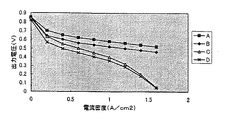
これらのセルの供給ガスに酸素、水素を用いた際の電流―電圧特性を図1に示す。運転条件は、供給ガス圧は2気圧で、それぞれ80℃の密閉水槽中でバブリングすることで加湿した。そして、セルの運転温度は75℃とし、各電流値での測定時の保持時間は5分とした。
【0054】
図1より、本発明によるセル(AおよびB)は、従来のセル(CおよびD)に比べて、各電流密度において出力電圧が高いことがわかる。特に、触媒層の細孔内および表層に有孔性のPVdFを配したAの出力はBと比べても高いことがわかる。これは本発明によれば、触媒層の細孔内および/または表層に高い撥水性を持つ有孔性のPVdFを配するために、電極の深部にまで活物質である水素および酸素の確実な供給が可能となり、従来の触媒層に比べて実際に作用する触媒層面積が大きいためである。特に、触媒層の細孔内および表層に有孔性のPVdFを配したセルAは良好な特性を示した。
【0055】
【発明の効果】
本発明の燃料電池用電極によれば、従来の電極に比べて実際に作用する電極面積が大きくなり、高性能な燃料電池の製造が可能となる。また、本発明の製造方法によれば、高性能な燃料電池の製造が可能な電極を製造することができる。
【図面の簡単な説明】
【図1】セルの電流―電圧特性を示す図。
【図2】本発明に係る燃料電池用電極の構造を示す模式図。
【図3】本発明に係る燃料電池用電極の構造を示す模式図。
【図4】本発明に係る燃料電池用電極の構造を示す模式図。
【図5】従来の燃料電池用電極の構造を示す模式図。
【符号の説明】
21、31、41:触媒粒子
22、32、42:固体高分子電解質
23、33、43:触媒層の細孔
24、34、44:有孔性樹脂
25、35、45:イオン交換膜
26、36、46:カーボン電極基材[0001]
BACKGROUND OF THE INVENTION
The present invention relates to a fuel cell electrode and a method for producing the same.
[0002]
[Prior art]
A solid polymer electrolyte fuel cell uses an ion exchange membrane as an electrolyte, and anode and cathode electrodes each having a catalyst layer and a gas diffusion layer containing a conductive porous body are bonded to both sides of the ion exchange membrane. It is a device that generates electricity through an electrochemical reaction by supplying hydrogen to the anode and oxygen to the cathode. The electrochemical reaction occurring at each electrode is shown below.
[0003]
Anode: H 2 → 2H + + 2e
Cathode: 1 / 2O 2 + 2H + + 2e → H 2 O
Total reaction: H 2 + 1 / 2O 2 → H 2 O
As is clear from this reaction formula, the reaction of each electrode proceeds only at the three-phase interface where the active material gas (hydrogen or oxygen), proton (H + ) and electron (e) can be exchanged simultaneously. To do.
[0004]
As shown in FIG. 5, the fuel cell electrode has a porous structure in which catalyst particles 51 and solid polymer electrolyte 52 are mixed and distributed in three dimensions, and a plurality of pores 54 are formed inside.
[0005]
The gas diffusion layer 58 is provided with a certain space in the surface layer of the
[0006]
On the other hand, in the
[0007]
In FIG. 5, reference numeral 53 denotes PTFE (polytetrafluoroethylene) particles, which play a role of imparting water repellency in the pores 54 of the
Here, the ion exchange membrane 55 serving as an electrolyte needs to be operated while keeping the inside of the battery in a wet state in order to show good proton conductivity in a water-containing state. Therefore, moisture management of the ion exchange membrane is performed by appropriately humidifying the hydrogen and oxygen supplied to the anode and the cathode so that the ion exchange membrane 55 is not dried.
[0008]
[Problems to be solved by the invention]
In the solid polymer electrolyte fuel cell, since pores in the catalyst layer form oxygen or hydrogen supply channels, water accumulates on the surface of the catalyst layer due to humidification of the supply gas as these active materials. Water blocks the gas supply inlet of the pores, hinders the gas supply into the pores, or water accumulates in the pores, and the supply of active material to the three-phase interface of the catalyst layer, especially the deep part of the electrode is delayed. In some cases, the working area is actually reduced and the battery performance cannot be taken out sufficiently. For this reason, moderate water repellency is imparted to the gas diffusion layer and the catalyst layer including the conductive porous body so that water does not accumulate.
[0009]
For example, in the case of carbon paper (thickness of 1.5 mm), which is a commonly used sintered carbon fiber, the carbon porous material is immersed in a PTFE particle dispersion solution to provide PTFE particles. Then, PTFE is coated on the carbon fiber surface by baking at about 350 ° C. for 15 minutes in a nitrogen atmosphere.
[0010]
On the other hand, imparting water repellency to the catalyst layer is achieved by applying PTFE particles to a catalyst layer paste composed of catalyst-supported carbon particles in which noble metal particles such as platinum are supported in a highly dispersed state on a carbon particle carrier that is catalyst particles and a solid polymer electrolyte solution. This is done by mixing the dispersion solution.
[0011]
However, at present, the water repellency of the catalyst layer and the conductive porous body is not sufficient, and in order to increase the output of the battery, let's improve the proton conductivity of the ion exchange membrane by supplying high-temperature and humidified gas. As a result, water accumulates in the pores of the catalyst layer and in the surface layer, and the supply of active material to the three-phase interface of the catalyst layer, particularly to the deep part of the electrode, is stagnated, the actual working area is reduced, and the battery performance can be sufficiently extracted. There is no problem. In particular, since water is generated at the cathode during the reaction, water tends to accumulate in the pores.
[0012]
In order to avoid this, for example, in the catalyst layer, it is possible to increase the mixing ratio of the PTFE particle dispersion solution applied at the time of preparation of the catalyst layer to increase the water repellency of the catalyst layer, thereby making it difficult for water to accumulate in the pores and in the surface layer. What is necessary is that the proportion of the catalyst-supported carbon, the solid polymer electrolyte, and the pores decreases by the volume increase in the electrode of the PTFE particles, and the electron conduction channel, the proton conduction channel, oxygen or hydrogen, and the product water. The formation of the supply / discharge channel is obstructed, and the output of the battery is reduced.
[0013]
In addition, it is only necessary to increase the coating amount of the PTFE dispersion solution when imparting water repellency to the conductive porous body. However, if the amount is increased too much, the PTFE particles block the pores of the conductive porous body, and instead supply gas. Will be inhibited.
[0014]
In view of the above, the present invention improves the water repellency of the fuel cell electrode while preventing the occurrence of the above-described problems, thereby improving the performance of the fuel cell electrode.
[0015]
[Means for Solving the Problems]
Fuel cell electrode of the present invention are those having a catalyst layer containing a solid polymer electrolyte and catalyst particles and porous resin.
[0016]
The electrode for a fuel cell according to the first invention of the present application is an electrode for a fuel cell having a catalyst layer containing a solid polymer electrolyte and catalyst particles, and has an ion exchange group at a portion corresponding to the pore of the catalyst layer or / and on the surface thereof. It is characterized by comprising a water-repellent porous resin that does not .
[0017]
Fuel cell electrode according to the second aspect of the invention is provided with a gas diffusion layer for a fuel cell electrode comprising a conductive porous body according to
[0018]
In this case, the conductive porous body is more preferably made of a carbon material.
[0019]
The third invention of the present application is a method for producing an electrode for a fuel cell having a water-repellent porous resin not having an ion exchange group of the first invention of the present application, wherein the catalyst layer has a repellent property having no ion exchange group. A solution in which an aqueous resin is dissolved in a solvent a is included , and then the solvent a is replaced with a solvent b that is insoluble in the resin and compatible with the solvent a. .
Further, the fourth invention of the present application is a method for producing an electrode for a fuel cell comprising a water-repellent porous resin not having an ion exchange group of the second invention of the present application , in which the catalyst layer and the gas diffusion layer are laminated. After adding a solution in which water-repellent resin having no ion exchange group is dissolved in solvent a, the solvent a is insoluble in the resin and is compatible with the solvent a. It is characterized by undergoing a replacement step.
[0020]
In any of the above-described electrodes, a solid polymer electrolyte having an ion exchange function is used, and a porous resin having a water repellent property having no ion exchange function is used . And as resin which comprises the said porous resin, a fluororesin is more preferable and it is preferable to use a polyvinylidene fluoride (PVdF) type-resin among these.
[0021]
A third invention of the present application is a method for producing an electrode for a fuel cell comprising a water-repellent porous resin having no ion exchange group of the first invention of the present application , comprising a solid polymer electrolyte and a catalyst A solution in which a water-repellent resin not having an ion exchange group is dissolved in a solvent a in a catalyst layer containing particles, and then insoluble in the resin and compatible with the solvent a This is performed by immersing it in b, and replacing the solvent a with a solvent b that is insoluble in the resin and compatible with the solvent a.
[0022]
A fourth invention of the present application is a method for producing an electrode for a fuel cell provided with a water-repellent porous resin not having an ion exchange group of the second invention of the present application. That is, when the fuel cell electrode has a structure in which a solid polymer electrolyte, a catalyst layer containing catalyst particles, and a conductive porous body are laminated, the lamination of the catalyst layer and the gas diffusion layer is performed. After including a solution of a water-repellent resin having no ion exchange group in the solvent in the solvent a, the laminate is immersed in the solvent b that is insoluble in the resin and compatible with the solvent a. The solvent a is replaced with a solvent b that is insoluble in the resin and compatible with the solvent a.
[0023]
DETAILED DESCRIPTION OF THE INVENTION
Hereinafter, the present invention will be described in more detail by explaining the structural examples of the fuel cell electrode according to the present invention with reference to the drawings. 2, 3 and 4 are schematic views showing structural examples of fuel cell electrodes according to the present invention.
[0024]
As shown in these drawings, the catalyst layer comprising the solid polymer electrolyte and the catalyst particles referred to in the present invention is a mixture of the
[0025]
The fuel cell electrode shown in FIG. 2 is provided with a
[0026]
In addition, since the pores are eliminated by disposing a water-repellent porous resin having no ion exchange group in the pores, this portion is called a pore equivalent portion. In the figure,
[0027]
According to the present invention, the water repellency of the pore-corresponding portion or / and the surface layer is increased by disposing the water-repellent resin having no porous ion exchange function on the pore-corresponding portion or / and the surface layer of the catalyst layer. . This prevents water from accumulating on the surface layer of the catalyst layer and covering the pores, and also prevents water from stagnation in the pores. The catalyst layer is supplied without stagnation to the three-phase interface of the layer, and high activation of the catalyst layer is achieved.
[0028]
In addition, even if it arrange | positions the water-repellent porous resin which does not have an ion exchange group only in a pore like FIG. 2, or only on the surface layer like FIG. 3, the effect of this invention is acquired, As shown in FIG. 4, higher activity can be achieved by arranging a water-repellent porous resin having no ion exchange group in the pore equivalent portion of the base of the catalyst layer and on the surface layer.
[0029]
In addition , the water-repellent porous resin having no ion exchange group may be disposed on the entire surface of the catalyst layer base as shown in these figures, but a part of the surface layer, and / or You may arrange | position to a part in pore.
[0030]
As the catalyst particles used in the electrode of the present invention, platinum group metals such as platinum, rhodium, ruthenium, iridium, palladium, osnium and alloy particles thereof, or catalyst-carrying carbon carrying these catalysts are suitable. The molecular electrolyte is preferably made of an ion exchange resin, preferably perfluorosulfonic acid or a styrene-divinylbenzene sulfonic acid type solid polymer electrolyte.
[0031]
Here, the pores of the porous resin are preferably open cells so that the active material can be smoothly supplied and discharged. The pore diameter is preferably 1 μm or less, more preferably 0.5 μm or less, and the porosity of the effective resin is preferably 45% or more in terms of gas supply, water discharge, and the like. . It is preferable to use a solvent extraction method as a method for producing a porous polymer capable of obtaining dense open cells. That is, by replacing the solvent a in the solution in which the resin is dissolved with a solvent b insoluble in the resin and compatible with the solvent a, the solvent a in the solution in which the resin is dissolved is extracted. The part from which the solvent a has been removed becomes pores to obtain a porous resin.
[0032]
Here, the porous resin used in the present invention is polyether such as polyvinyl chloride, polyacrylonitrile, polyethylene oxide, polypropylene oxide, polyacrylonitrile, vinylidene fluoride polymer, polyvinylidene chloride, polymethyl methacrylate, polymethyl acrylate. , Polyvinyl alcohol, polymethacrylonitrile, polyvinyl acetate, polyvinyl pyrrolidone, polyethyleneimine, polybutadiene, polystyrene, polyisoprene, or derivatives thereof may be used alone or in combination, and constitutes the above resin A resin obtained by copolymerization of various monomers may be used, but preferably a fluororesin having high water repellency, such as ethylene trifluoride chloride copolymer (PCTFE), vinylidene fluoride polymer (PVdF), fluoropolymer. Fluorinated homopolymers such as vinyl fluoride polymer (PVF), ethylene / tetrafluoroethylene copolymer (ETFE), tetrafluoroethylene / hexafluoropropylene copolymer (EPE), vinylidene fluoride copolymer Fluorine-containing copolymers such as are preferable, and a mixture thereof may be used.
[0033]
Then, when a porous fluororesin is produced by the previous solvent extraction method, fine and uniform pores are obtained, so that PVdF homopolymer, vinylidene fluoride / hexafluoropropylene copolymer (P (VdF-HFP )) Or a polyvinylidene fluoride (PVdF) resin such as a vinylidene fluoride / tetrafluoroethylene copolymer (P (VdF-TFP)). Among them, a vinylidene fluoride polymer (PVdF) excellent in water repellency or a soft vinylidene fluoride / hexafluoropropylene copolymer (P (VdF-HFP)) that is easy to handle is preferable.
[0034]
Solvent a that dissolves the resin may be any as long as it dissolves the resin. Carbonic acid esters such as dimethylformamide, propylene carbonate, ethylene carbonate, dimethyl carbonate, diethyl carbonate, and ethyl methyl carbonate, dimethyl ether, diethyl ether, and ethyl methyl ether , Ethers such as tetrahydrofuran, dimethylacetamide, 1-methyl-pyrrolidinone, n-methyl-pyrrolidone and the like.
[0035]
As the extraction solvent b, water or a mixed solution of water and alcohol is preferable because it is inexpensive.
[0036]
In these combinations, polyvinylidene fluoride (PVdF) or P (VdF-HFP) dissolved in n-methylpyrrolidone (NMP) is extracted with water or a mixed solution of water and alcohol. It is preferable in terms of uniformity of pore diameter.
[0037]
Such an electrode for a fuel cell of the present invention is formed, for example, by forming a catalyst layer paste containing catalyst-carrying carbon particles, a solid polymer electrolyte solution and, if necessary, a PTFE particle dispersion solution into a polymer film (generally, A conventional catalyst layer produced by a method such as heating and drying after a film thickness of 3 to 30 μm), or catalyst-carrying carbon particles in which noble metal particles such as platinum are supported in a highly dispersed manner on a carbon particle carrier and, if necessary, Is a method of forming a catalyst layer paste to which a PTFE particle dispersion solution has been added on a polymer film (generally having a film thickness of 3 to 30 μm), heating and drying, and then applying and impregnating a solid polymer electrolyte solution thereon. A solution obtained by dissolving a resin in a solvent a in a conventional catalyst layer thus prepared is applied or dipped, and then insoluble in the resin. Can be obtained by replacing the solvent a solvent b which with a compatible.
Alternatively, after forming a catalyst layer paste (generally having a film thickness of 3 to 30 μm) on the conductive porous body, the catalyst-supporting carbon particles, the solid polymer electrolyte solution, and, if necessary, the PTFE particle dispersion solution are added. , A conventional electrode produced by a method such as heating and drying, or a catalyst-supported carbon particle in which noble metal particles such as platinum are supported on a carbon particle support in a highly dispersed state and a catalyst in which a PTFE particle-dispersed solution is added if necessary A conventional electrode produced by forming a layer paste on a conductive porous body (generally having a film thickness of 3 to 30 μm), heating and drying, and then applying and impregnating a solid polymer electrolyte solution thereon Then, after a solution obtained by dissolving the resin in the solvent a is included by coating or dipping, the solvent a is placed in a solvent b that is insoluble in the resin and compatible with the solvent a. It can be obtained by.
[0038]
In particular, according to the latter production method, in a fuel cell electrode including a catalyst layer containing a solid polymer electrolyte and catalyst particles and a gas diffusion electrode containing a conductive porous body, the catalyst layer and the conductivity Since the porous body contains a water-repellent porous resin having no ion exchange group , a fuel cell electrode having high activity can be expected. In this case, if a fluororesin having high water repellency is used, there is no need to impart water repellency to the conductive porous body in advance, and the porous resin disposed in the conductive porous body plays a role in this. Take on.
[0039]
Here, as the conductive porous body, foamed nickel, titanium fiber sintered body or the like can be used, but a porous carbon base material is preferable from the viewpoint of conductivity, weight, etc., and a sintered body of carbon fiber, etc. Is good.
[0040]
【Example】
The present invention will be described below with reference to preferred embodiments.
[0041]
[Example 1]
A conductive porous material is made of a catalyst layer paste made of platinum-supported carbon (Tanaka Kikinzoku, 10V30E: Valcan XC-72 with 30 wt% platinum supported) and a solid polymer electrolyte solution (Aldrich,
[0042]
The electrode A has a structure in which an effective PVdF resin is disposed in the pores of the catalyst layer and on the surface layer, and further on the conductive porous body.
[0043]
The amount of platinum-supporting carbon at the time of preparing the paste was adjusted so that the amount of platinum in electrode A was about 1.0 mg / cm 2 .
[0044]
Furthermore, the electrode A was joined to both surfaces of an ion exchange membrane (manufactured by DuPont, Nafion, film thickness of about 50 μm) with a hot press (140 ° C.), and assembled into a single cell of a fuel cell to obtain a cell A.
[0045]
[Example 2]
A paste made of platinum-supported carbon (Tanaka Kikinzoku, 10V30E: 30% by weight of platinum supported on Valcan XC-72) and a solid polymer electrolyte solution (Aldrich,
[0046]
The catalyst layer B has a structure in which a porous PVdF resin is mainly disposed on the surface layer.
[0047]
The amount of platinum-supported carbon at the time of preparing the paste was adjusted so that the amount of platinum on one surface of the catalyst layer B-ion exchange membrane assembly was about 1.0 mg / cm 2 .
[0048]
A conductive porous carbon sheet (0.5 mm) imparted with water repellency to serve as a gas diffusion layer on both surfaces of this joined body was joined by hot pressing, and assembled into a single cell of a fuel cell to obtain cell B. .
[Comparative Example 1]
Platinum-supported carbon (manufactured by Tanaka Kikinzoku, 10V30E: 30% by weight of platinum supported on Valcan XC-72), solid polymer electrolyte solution (manufactured by Aldrich, 5% by weight Nafion solution), and PTFE particle dispersion solution (manufactured by DuPont Mitsui Chemicals, A paste made of Teflon 30J) is coated on a conductive porous carbon electrode substrate (0.5 mm) imparted with water repellency, and dried in a nitrogen atmosphere at 120 ° C. for 1 hour, and fuel cell electrode C Got.
[0049]
The amount of platinum-supporting carbon at the time of preparing the paste was adjusted so that the amount of platinum in electrode C was about 1.0 mg / cm 2 .
[0050]
Further, the electrode C was joined to both surfaces of an ion exchange membrane (manufactured by DuPont, Nafion, film thickness of about 50 μm) with a hot press (140 ° C.), and assembled into a single cell of a fuel cell to obtain a cell C.
[0051]
[Comparative Example 2]
Platinum-supported carbon (manufactured by Tanaka Kikinzoku, 10V30E: 30% by weight of platinum supported on Valcan XC-72), solid polymer electrolyte (manufactured by Aldrich, 5% by weight of Nafion) and PTFE particle dispersion (manufactured by Mitsui Dupont Fluorochemical, Teflon) 30J) is applied onto a polymer film (PFA) and naturally dried for about 1 hour. An electrode obtained by hot pressing (140 ° C.) is subjected to ion exchange membrane (manufactured by DuPont, Nafion, membrane). The catalyst layer D-ion exchange membrane assembly was obtained by bonding to both surfaces having a thickness of about 50 μm.
The amount of platinum-supported carbon at the time of preparing the paste was adjusted so that the amount of platinum on one side of the catalyst layer D-ion exchange membrane assembly was about 1.0 mg / cm 2 .
[0052]
Conductive porous carbon sheets (0.5 mm) imparted with water repellency to serve as gas diffusion layers on both sides of this joined body were joined by hot pressing, and assembled into a single cell of a fuel cell to obtain cell D. .
[0053]
FIG. 1 shows current-voltage characteristics when oxygen and hydrogen are used as the supply gas of these cells. The operating conditions were that the supply gas pressure was 2 atm, and each was humidified by bubbling in a sealed water bath at 80 ° C. The operating temperature of the cell was 75 ° C., and the holding time during measurement at each current value was 5 minutes.
[0054]
FIG. 1 shows that the cells (A and B) according to the present invention have a higher output voltage at each current density than the conventional cells (C and D). In particular, it can be seen that the output of A in which porous PVdF is arranged in the pores of the catalyst layer and in the surface layer is higher than that of B. This is because, according to the present invention, in order to arrange porous PVdF having high water repellency in the pores of the catalyst layer and / or in the surface layer, it is possible to ensure the active material hydrogen and oxygen to the deep part of the electrode. This is because supply is possible and the area of the catalyst layer actually acting is larger than that of the conventional catalyst layer. In particular, the cell A in which porous PVdF was disposed in the pores of the catalyst layer and in the surface layer showed good characteristics.
[0055]
【The invention's effect】
According to the electrode for a fuel cell of the present invention, the electrode area that actually acts is larger than that of a conventional electrode, and a high-performance fuel cell can be manufactured. Moreover, according to the manufacturing method of the present invention, an electrode capable of manufacturing a high-performance fuel cell can be manufactured.
[Brief description of the drawings]
FIG. 1 is a graph showing current-voltage characteristics of a cell.
FIG. 2 is a schematic diagram showing the structure of a fuel cell electrode according to the present invention.
FIG. 3 is a schematic diagram showing the structure of a fuel cell electrode according to the present invention.
FIG. 4 is a schematic diagram showing the structure of a fuel cell electrode according to the present invention.
FIG. 5 is a schematic view showing the structure of a conventional fuel cell electrode.
[Explanation of symbols]
21, 31, 41:
Claims (4)
Priority Applications (3)
| Application Number | Priority Date | Filing Date | Title |
|---|---|---|---|
| JP07888999A JP4320482B2 (en) | 1998-10-03 | 1999-03-24 | Fuel cell electrode and manufacturing method thereof |
| DE10004955A DE10004955A1 (en) | 1999-02-05 | 2000-02-04 | Electrode used for a fuel cell comprises a porous polymer and a catalyst layer containing a solid polymer electrolyte and catalyst particles |
| US09/497,515 US7147957B1 (en) | 1999-02-05 | 2000-02-04 | Electrode for fuel cell and manufacturing method therefor |
Applications Claiming Priority (3)
| Application Number | Priority Date | Filing Date | Title |
|---|---|---|---|
| JP29615898 | 1998-10-03 | ||
| JP10-296158 | 1998-10-03 | ||
| JP07888999A JP4320482B2 (en) | 1998-10-03 | 1999-03-24 | Fuel cell electrode and manufacturing method thereof |
Publications (3)
| Publication Number | Publication Date |
|---|---|
| JP2000173625A JP2000173625A (en) | 2000-06-23 |
| JP2000173625A5 JP2000173625A5 (en) | 2006-04-27 |
| JP4320482B2 true JP4320482B2 (en) | 2009-08-26 |
Family
ID=26419952
Family Applications (1)
| Application Number | Title | Priority Date | Filing Date |
|---|---|---|---|
| JP07888999A Expired - Fee Related JP4320482B2 (en) | 1998-10-03 | 1999-03-24 | Fuel cell electrode and manufacturing method thereof |
Country Status (1)
| Country | Link |
|---|---|
| JP (1) | JP4320482B2 (en) |
Cited By (1)
| Publication number | Priority date | Publication date | Assignee | Title |
|---|---|---|---|---|
| US7894118B2 (en) | 2008-03-11 | 2011-02-22 | Ricoh Company, Ltd. | Electrochromic compound, electrochromic composition and display device |
Families Citing this family (2)
| Publication number | Priority date | Publication date | Assignee | Title |
|---|---|---|---|---|
| WO2006064594A1 (en) * | 2004-12-17 | 2006-06-22 | Nec Corporation | Solid polymer type fuel cell |
| GB2558058A (en) * | 2016-10-26 | 2018-07-04 | Merck Patent Gmbh | Immersion-cast catalyst layers for fuel cells and a method for their production |
-
1999
- 1999-03-24 JP JP07888999A patent/JP4320482B2/en not_active Expired - Fee Related
Cited By (1)
| Publication number | Priority date | Publication date | Assignee | Title |
|---|---|---|---|---|
| US7894118B2 (en) | 2008-03-11 | 2011-02-22 | Ricoh Company, Ltd. | Electrochromic compound, electrochromic composition and display device |
Also Published As
| Publication number | Publication date |
|---|---|
| JP2000173625A (en) | 2000-06-23 |
Similar Documents
| Publication | Publication Date | Title |
|---|---|---|
| JP6408562B2 (en) | Self-humidifying membrane / electrode assembly and fuel cell equipped with the same | |
| JP2001345106A (en) | Electrode for fuel cell and manufacturing method | |
| JP3594533B2 (en) | Fuel cell | |
| JPH11288727A (en) | Solid high polymer fuel cell film/electrode junction body | |
| US20110008706A1 (en) | Polymer coating of pem fuel cell catalyst layers | |
| KR100773669B1 (en) | Direct-type fuel cell and direct-type fuel cell system | |
| US20190280307A1 (en) | Composite electrode layer for polymer electrolyte fuel cell | |
| JP2002100372A (en) | Gas diffusion electrode for fuel cell and its manufacturing method | |
| KR102084568B1 (en) | Component for fuel cell including graphene foam and functioning as flow field and gas diffusion layer | |
| CA2568763C (en) | Cell module having water permeable hollow body, and fuel cell comprising cell module | |
| JP2009199988A (en) | Anode electrode for direct methanol fuel cell and direct methanol type fuel cell using the same | |
| JP5079195B2 (en) | Gas diffusion electrode for fuel cell and manufacturing method thereof | |
| JPH07326363A (en) | Ion conductivity imparting electrode and jointing material for electrode and electrolyte and cell using the ion conductivity imparting electrode | |
| JP3813406B2 (en) | Fuel cell | |
| JP5354982B2 (en) | Direct oxidation fuel cell | |
| JP4433552B2 (en) | Composite catalyst and production method thereof | |
| JP4880131B2 (en) | Gas diffusion electrode and fuel cell using the same | |
| JP5023591B2 (en) | Membrane / electrode assembly for fuel cells | |
| JP4403634B2 (en) | Composite catalyst for solid polymer electrolyte fuel cell. | |
| JP4320482B2 (en) | Fuel cell electrode and manufacturing method thereof | |
| US7147957B1 (en) | Electrode for fuel cell and manufacturing method therefor | |
| US11616247B2 (en) | Multi-interface membrane electrode assembly | |
| JP4180556B2 (en) | Polymer electrolyte fuel cell | |
| JP2006085984A (en) | Mea for fuel cell and fuel cell using this | |
| JP2001093544A (en) | Electrode of fuel cell, method for manufacturing and fuel cell |
Legal Events
| Date | Code | Title | Description |
|---|---|---|---|
| A711 | Notification of change in applicant |
Free format text: JAPANESE INTERMEDIATE CODE: A712 Effective date: 20051213 |
|
| A521 | Written amendment |
Free format text: JAPANESE INTERMEDIATE CODE: A523 Effective date: 20060313 |
|
| A621 | Written request for application examination |
Free format text: JAPANESE INTERMEDIATE CODE: A621 Effective date: 20060313 |
|
| A977 | Report on retrieval |
Free format text: JAPANESE INTERMEDIATE CODE: A971007 Effective date: 20080317 |
|
| A131 | Notification of reasons for refusal |
Free format text: JAPANESE INTERMEDIATE CODE: A131 Effective date: 20080326 |
|
| A521 | Written amendment |
Free format text: JAPANESE INTERMEDIATE CODE: A523 Effective date: 20080509 |
|
| A131 | Notification of reasons for refusal |
Free format text: JAPANESE INTERMEDIATE CODE: A131 Effective date: 20081002 |
|
| A521 | Written amendment |
Free format text: JAPANESE INTERMEDIATE CODE: A523 Effective date: 20081030 |
|
| TRDD | Decision of grant or rejection written | ||
| A01 | Written decision to grant a patent or to grant a registration (utility model) |
Free format text: JAPANESE INTERMEDIATE CODE: A01 Effective date: 20090507 |
|
| A01 | Written decision to grant a patent or to grant a registration (utility model) |
Free format text: JAPANESE INTERMEDIATE CODE: A01 |
|
| A61 | First payment of annual fees (during grant procedure) |
Free format text: JAPANESE INTERMEDIATE CODE: A61 Effective date: 20090520 |
|
| R150 | Certificate of patent or registration of utility model |
Free format text: JAPANESE INTERMEDIATE CODE: R150 |
|
| FPAY | Renewal fee payment (event date is renewal date of database) |
Free format text: PAYMENT UNTIL: 20120612 Year of fee payment: 3 |
|
| FPAY | Renewal fee payment (event date is renewal date of database) |
Free format text: PAYMENT UNTIL: 20120612 Year of fee payment: 3 |
|
| S111 | Request for change of ownership or part of ownership |
Free format text: JAPANESE INTERMEDIATE CODE: R313111 |
|
| FPAY | Renewal fee payment (event date is renewal date of database) |
Free format text: PAYMENT UNTIL: 20120612 Year of fee payment: 3 |
|
| R360 | Written notification for declining of transfer of rights |
Free format text: JAPANESE INTERMEDIATE CODE: R360 |
|
| FPAY | Renewal fee payment (event date is renewal date of database) |
Free format text: PAYMENT UNTIL: 20120612 Year of fee payment: 3 |
|
| R360 | Written notification for declining of transfer of rights |
Free format text: JAPANESE INTERMEDIATE CODE: R360 |
|
| R371 | Transfer withdrawn |
Free format text: JAPANESE INTERMEDIATE CODE: R371 |
|
| S111 | Request for change of ownership or part of ownership |
Free format text: JAPANESE INTERMEDIATE CODE: R313111 |
|
| FPAY | Renewal fee payment (event date is renewal date of database) |
Free format text: PAYMENT UNTIL: 20120612 Year of fee payment: 3 |
|
| R350 | Written notification of registration of transfer |
Free format text: JAPANESE INTERMEDIATE CODE: R350 |
|
| FPAY | Renewal fee payment (event date is renewal date of database) |
Free format text: PAYMENT UNTIL: 20120612 Year of fee payment: 3 |
|
| FPAY | Renewal fee payment (event date is renewal date of database) |
Free format text: PAYMENT UNTIL: 20130612 Year of fee payment: 4 |
|
| LAPS | Cancellation because of no payment of annual fees |