JP4319665B2 - Method and apparatus for multiplexing data and control information in a radio communication system based on frequency division multiple access - Google Patents
Method and apparatus for multiplexing data and control information in a radio communication system based on frequency division multiple access Download PDFInfo
- Publication number
- JP4319665B2 JP4319665B2 JP2006129660A JP2006129660A JP4319665B2 JP 4319665 B2 JP4319665 B2 JP 4319665B2 JP 2006129660 A JP2006129660 A JP 2006129660A JP 2006129660 A JP2006129660 A JP 2006129660A JP 4319665 B2 JP4319665 B2 JP 4319665B2
- Authority
- JP
- Japan
- Prior art keywords
- data
- symbol block
- control information
- unit
- information
- Prior art date
- Legal status (The legal status is an assumption and is not a legal conclusion. Google has not performed a legal analysis and makes no representation as to the accuracy of the status listed.)
- Active
Links
Images


Classifications
-
- H—ELECTRICITY
- H04—ELECTRIC COMMUNICATION TECHNIQUE
- H04L—TRANSMISSION OF DIGITAL INFORMATION, e.g. TELEGRAPHIC COMMUNICATION
- H04L27/00—Modulated-carrier systems
- H04L27/26—Systems using multi-frequency codes
- H04L27/2601—Multicarrier modulation systems
- H04L27/2626—Arrangements specific to the transmitter only
- H04L27/2627—Modulators
- H04L27/2634—Inverse fast Fourier transform [IFFT] or inverse discrete Fourier transform [IDFT] modulators in combination with other circuits for modulation
- H04L27/2636—Inverse fast Fourier transform [IFFT] or inverse discrete Fourier transform [IDFT] modulators in combination with other circuits for modulation with FFT or DFT modulators, e.g. standard single-carrier frequency-division multiple access [SC-FDMA] transmitter or DFT spread orthogonal frequency division multiplexing [DFT-SOFDM]
-
- H—ELECTRICITY
- H04—ELECTRIC COMMUNICATION TECHNIQUE
- H04L—TRANSMISSION OF DIGITAL INFORMATION, e.g. TELEGRAPHIC COMMUNICATION
- H04L5/00—Arrangements affording multiple use of the transmission path
- H04L5/003—Arrangements for allocating sub-channels of the transmission path
- H04L5/0044—Arrangements for allocating sub-channels of the transmission path allocation of payload
-
- H—ELECTRICITY
- H04—ELECTRIC COMMUNICATION TECHNIQUE
- H04L—TRANSMISSION OF DIGITAL INFORMATION, e.g. TELEGRAPHIC COMMUNICATION
- H04L27/00—Modulated-carrier systems
- H04L27/26—Systems using multi-frequency codes
- H04L27/2601—Multicarrier modulation systems
- H04L27/2614—Peak power aspects
-
- H—ELECTRICITY
- H04—ELECTRIC COMMUNICATION TECHNIQUE
- H04L—TRANSMISSION OF DIGITAL INFORMATION, e.g. TELEGRAPHIC COMMUNICATION
- H04L27/00—Modulated-carrier systems
- H04L27/26—Systems using multi-frequency codes
- H04L27/2601—Multicarrier modulation systems
- H04L27/2647—Arrangements specific to the receiver only
- H04L27/2649—Demodulators
- H04L27/26524—Fast Fourier transform [FFT] or discrete Fourier transform [DFT] demodulators in combination with other circuits for demodulation
- H04L27/26526—Fast Fourier transform [FFT] or discrete Fourier transform [DFT] demodulators in combination with other circuits for demodulation with inverse FFT [IFFT] or inverse DFT [IDFT] demodulators, e.g. standard single-carrier frequency-division multiple access [SC-FDMA] receiver or DFT spread orthogonal frequency division multiplexing [DFT-SOFDM]
-
- H—ELECTRICITY
- H04—ELECTRIC COMMUNICATION TECHNIQUE
- H04L—TRANSMISSION OF DIGITAL INFORMATION, e.g. TELEGRAPHIC COMMUNICATION
- H04L5/00—Arrangements affording multiple use of the transmission path
- H04L5/003—Arrangements for allocating sub-channels of the transmission path
- H04L5/0053—Allocation of signaling, i.e. of overhead other than pilot signals
-
- H—ELECTRICITY
- H04—ELECTRIC COMMUNICATION TECHNIQUE
- H04L—TRANSMISSION OF DIGITAL INFORMATION, e.g. TELEGRAPHIC COMMUNICATION
- H04L25/00—Baseband systems
- H04L25/02—Details ; arrangements for supplying electrical power along data transmission lines
- H04L25/0202—Channel estimation
- H04L25/0224—Channel estimation using sounding signals
-
- H—ELECTRICITY
- H04—ELECTRIC COMMUNICATION TECHNIQUE
- H04L—TRANSMISSION OF DIGITAL INFORMATION, e.g. TELEGRAPHIC COMMUNICATION
- H04L27/00—Modulated-carrier systems
- H04L27/26—Systems using multi-frequency codes
- H04L27/2601—Multicarrier modulation systems
- H04L27/2647—Arrangements specific to the receiver only
-
- H—ELECTRICITY
- H04—ELECTRIC COMMUNICATION TECHNIQUE
- H04L—TRANSMISSION OF DIGITAL INFORMATION, e.g. TELEGRAPHIC COMMUNICATION
- H04L5/00—Arrangements affording multiple use of the transmission path
- H04L5/0001—Arrangements for dividing the transmission path
- H04L5/0003—Two-dimensional division
- H04L5/0005—Time-frequency
- H04L5/0007—Time-frequency the frequencies being orthogonal, e.g. OFDM(A), DMT
-
- H—ELECTRICITY
- H04—ELECTRIC COMMUNICATION TECHNIQUE
- H04L—TRANSMISSION OF DIGITAL INFORMATION, e.g. TELEGRAPHIC COMMUNICATION
- H04L5/00—Arrangements affording multiple use of the transmission path
- H04L5/003—Arrangements for allocating sub-channels of the transmission path
- H04L5/0048—Allocation of pilot signals, i.e. of signals known to the receiver
-
- H—ELECTRICITY
- H04—ELECTRIC COMMUNICATION TECHNIQUE
- H04L—TRANSMISSION OF DIGITAL INFORMATION, e.g. TELEGRAPHIC COMMUNICATION
- H04L5/00—Arrangements affording multiple use of the transmission path
- H04L5/0091—Signaling for the administration of the divided path
- H04L5/0094—Indication of how sub-channels of the path are allocated
Description
本発明は、周波数分割多重接続基盤の無線通信システムに係り、詳しくは、データと制御情報とを多重化して転送する方法及び装置に関する。 The present invention relates to a radio communication system based on frequency division multiple access, and more particularly, to a method and apparatus for multiplexing and transferring data and control information.
近年、放送及び移動通信システムの技術の発達に伴い、直交周波数分割多重(Orthogonal Frequency Division Multiplexing;以下、「OFDM」と称する。)転送技術が汎用されている。OFDM技術は、無線通信チャンネルによく見られるマルチパス信号成分間の干渉を排除して多重接続ユーザ間の直交性を保証すると共に、周波数資源の効率よい使用を可能にするものである。この理由から、OFDM技術は、既存のコード分割多重接続(Code Division Multiple Access;以下、「CDMA」と称する。)技術と比較して、データの高速転送が可能であり、しかも、広域システムに有用な技術とされている。しかしながら、上記OFDM技術は、マルチキャリア転送技術であって、送信データを多数のサブキャリアに分けて載せて並列転送するが故に、送信信号の最大電力対平均電力比(Peak-to-Average Power Ratio;以下、「PAPR」と称する。)を高めてしまうという不都合がある。 In recent years, with the development of broadcasting and mobile communication systems, orthogonal frequency division multiplexing (hereinafter referred to as “OFDM”) transfer technology has been widely used. OFDM technology eliminates interference between multipath signal components often found in wireless communication channels to ensure orthogonality among multiple connected users and allows efficient use of frequency resources. For this reason, the OFDM technology is capable of high-speed data transfer compared to the existing Code Division Multiple Access (hereinafter referred to as “CDMA”) technology, and is useful for a wide area system. Technology. However, the OFDM technique is a multi-carrier transfer technique and transmits transmission data divided into a large number of subcarriers in parallel, so that the maximum power-to-average power ratio (Peak-to-Average Power Ratio) of the transmission signal is increased. Hereinafter referred to as “PAPR”).
PAPRが高いと、送信機の無線周波数(RF)の電力増幅器からの出力信号に歪みを生じさせるため、送信機は、このような不都合を防ぐために、増幅器の入力電力を減らす電力バックオフを必要とする。このため、OFDM技術を移動通信システムの上りリンクに適用する場合、端末が転送信号に対して電力バックオフを行う必要があり、その結果、セルカバーリッジが低減することになる。 A high PAPR causes distortion in the output signal from the transmitter's radio frequency (RF) power amplifier, so the transmitter needs a power back-off that reduces the amplifier's input power to prevent this inconvenience. And For this reason, when the OFDM technology is applied to the uplink of a mobile communication system, the terminal needs to perform power back-off for the transfer signal, and as a result, cell coverage is reduced.
上記OFDM技術のPAPR問題を解決できる技術として、近年、IFDMA(Interleaved Frequency Division Multiple Access)に関する研究が盛んに行われている。IFDMAは、OFDMと同様に、多重接続ユーザ間の直交性を保証できるシングルキャリア転送基盤の技術であって、送信信号のPAPRが非常に低いというメリットがある。このため、上記IFDMAを移動通信システムに適用する場合、OFDM技術に比べてPAPRによるセルカバーリッジの減少の問題が抑えられる。 In recent years, research on IFDMA (Interleaved Frequency Division Multiple Acces) has been actively conducted as a technique that can solve the PAPR problem of the OFDM technique. IFDMA, like OFDM, is a single carrier transfer-based technology that can guarantee orthogonality between multiple connected users, and has the advantage that the PAPR of the transmission signal is very low. Therefore, when IFDMA is applied to a mobile communication system, the problem of cell coverage reduction due to PAPR can be suppressed as compared with OFDM technology.
図1は、通常のIFDMA送信機の構造図である。 FIG. 1 is a structural diagram of a normal IFDMA transmitter.
図1には、高速フーリエ変換(Fast Fourier Transform;以下、「FFT」と称する。)104と、逆高速フーリエ変換(Inverse Fast Fourier Transform;以下、「IFFT」と称する。)106とを用いた構造を示しているが、他の具現方法も採用可能である。このようなFFT104とIFFT106とを用いた具現は、ハードウェアの複雑度が高くないことから、IFDMAシステムのパラメータの変更を変更し易くするというメリットがある。 In FIG. 1, a structure using a Fast Fourier Transform (hereinafter referred to as “FFT”) 104 and an Inverse Fast Fourier Transform (hereinafter referred to as “IFFT”) 106. However, other implementation methods can be employed. Such implementation using the FFT 104 and the IFFT 106 has an advantage that it is easy to change the change of the parameters of the IFDMA system because the hardware complexity is not high.
OFDMとIFDMAとの違いを送信機の構造の点からみたとき、OFDM送信機においてマルチキャリアの転送に用いられるIFFT106に加えて、IFDMA送信機においては、FFT104が上記IFFT106の前端にさらに設けられる。このため、図1に示すように、M個の送信変調シンボル100が集まってなるブロック単位で上記FFT104に入力する。上記ブロックを以下ではシンボルブロックと呼び、上記シンボルブロックがFFTに入力する周期をシンボルブロック周期と言う。上記FFT104からの信号は、等間隔にてIFFT106の入力に印加され、これは、IFDMA送信信号成分が周波数領域において等間隔のサブキャリアを介して転送されるようにする。このような過程中に、通常、上記IFFT106の入出力サイズNは、上記FFT104の入出力サイズMに比べて大となる。OFDMにおいては、上記変調シンボルブロック100が上記FFT104を経ることなく直ちにIFFT106に入力し、多数のサブキャリアを介して転送されるので、高い値のPAPRが得られる。
When the difference between OFDM and IFDMA is considered in terms of the structure of the transmitter, in addition to the IFFT 106 used for multicarrier transfer in the OFDM transmitter, an
IFDMは、送信シンボルが上記IFFT106において最終的に処理されてマルチキャリアに転送されるにも拘わらず、その前に上記送信シンボルブロックを上記FFT104により前処理することにより、FFT104とIFFT106との相殺作用により上記IFFT106からの出力信号がシングルキャリアに転送されたのと同様な効果が得られ、これは、PAPRの低下につながる。また、最終的に、上記IFFT106からの出力を並列−直列変換器(PSC)102において直列ストリームに変換後、OFDMシステムのように、サイクリック及びプレフィックス(cyclic prefix;以下、「CP」と称する。)あるいは保護区間108を付けて転送することにより、マルチパスチャンネル信号成分同士の干渉を防ぐことができる。
Although IFDM is finally processed by the IFFT 106 and transferred to the multicarrier, the IFDM preliminarily processes the transmission symbol block by the
図2は、IFDMAとほとんど同じ技術であって、多重接続ユーザ間の直交性を保証すると共に、シングルキャリア転送を基盤とする、OFDMに比べて低いPAPRが得られるLFDMA(Localized Frequency Division Multiple Access)技術の送信機の構造を示す。図1と図2に示すように、送信機の構造面でLFDMA技術がIFDMA技術と異なる点は、FFT204からの出力が連続するインデックスのIFFT206入力に印加されるということである。このため、LFDMA送信信号を周波数領域において考慮すると、上記FFT204からの出力が上記IFFT206入力にマッピングされるときに用いられた隣り合うサブキャリアよりなる帯域を占める。換言すると、周波数領域において、IFDMA送信信号は、等間隔にて散在しているサブキャリア帯域を占め、LFDMA信号は、隣り合うサブキャリアよりなるサブキャリア帯域を占める。
FIG. 2 shows almost the same technology as IFDMA, which guarantees orthogonality between multiple connected users and provides low PAPR compared to OFDM based on single carrier transfer, which is LFDMA (Localized Frequency Division Multiple Access). The structure of the technology transmitter is shown. As shown in FIGS. 1 and 2, the difference between the LFDMA technique and the IFDMA technique in terms of the structure of the transmitter is that the output from the
上記IFDMA及びLFDMA基盤のシステムを放送あるいは移動通信システムに適用するためには、データ転送に加えて、上記データを受信器において復調・復号可能にするための制御情報及びパイロットの転送が必要となる。パイロットは、送信機と受信器との間の所定のパターンを持つため、無線フェージングチャンネルにより受信信号に歪みが生じた場合、受信器は、上記パイロットを基に上記無線フェージングチャンネルにより受信信号に生じた歪みを推定して除去することができる。一方、上記制御情報は、送信データに適用された変調方式、チャンネルコード方式、データブロックのサイズ、サブパケットIDなどの複合自動再送要求(Hybrid Automatic Repeat Request;以下、「HARQ」と称する。)関係の情報などを含んでいる。受信器は、上記制御情報を受信することにより、送信データに適用された上記情報を取得して受信データの復調・復号などの動作を行うことが可能になる。 In order to apply the IFDMA and LFDMA-based systems to broadcasting or mobile communication systems, in addition to data transfer, control information and pilot transfer for enabling the data to be demodulated / decoded at the receiver are required. . Since the pilot has a predetermined pattern between the transmitter and the receiver, when the received signal is distorted by the radio fading channel, the receiver is generated in the received signal by the radio fading channel based on the pilot. The estimated distortion can be removed. On the other hand, the control information relates to a hybrid automatic repeat request (hereinafter referred to as “HARQ”) such as a modulation scheme applied to transmission data, a channel code scheme, a data block size, and a subpacket ID. Information. By receiving the control information, the receiver can acquire the information applied to the transmission data and perform operations such as demodulation and decoding of the reception data.
現在、移動通信システムに汎用されているCDMA技術においては、上記データ、制御情報、パイロットなどに相異なるチャンネル区分コードを適用して転送することにより、受信器が上記信号を干渉無しに分離して検出できるようにしている。一方、OFDM技術においては、上記データ、制御情報、パイロットなどを相異なるサブキャリアに載せて送るか、あるいは時分割して送る。 Currently, in CDMA technology widely used in mobile communication systems, the receiver separates the signal without interference by applying different channel classification codes to the data, control information, pilot, etc. It can be detected. On the other hand, in the OFDM technique, the data, control information, pilot, etc. are sent on different subcarriers or are sent in time division.
しかしながら、通常、上記制御情報は、1タイムスロットを全て占める程度に情報量が多くないため、上記時分割基盤の多重化方式を採用する場合、資源の無駄遣いが起こることがある。そして、上記制御情報をOFDM技術に適用するように、データとは異なる別途のサブキャリアを用いて転送する場合、送信信号のPAPRが高くなるという不都合がある。 However, since the control information usually does not have a large amount of information to the extent that it occupies one time slot, when the time division based multiplexing method is adopted, resources may be wasted. When the control information is transferred using a separate subcarrier different from the data so as to be applied to the OFDM technology, there is a disadvantage that the PAPR of the transmission signal becomes high.
本発明は上記事情に鑑みてなされたものであり、その目的は、IFDMA及びLFDMA基盤の通信システムにおいて、送信信号のPAPRを低減し、かつ資源を有効利用できるようにデータと制御情報とを多重化する方法及び装置を提供するところにある。 The present invention has been made in view of the above circumstances, and an object of the present invention is to multiplex data and control information in an IFDMA and LFDMA-based communication system so as to reduce the PAPR of a transmission signal and effectively use resources. There is a need to provide a method and apparatus.
また、本発明は、IFDMA及びLFDMA基盤の通信システムにおいて、データと制御情報とを1つのFFTブロック周期内におけるFFT入力端において多重化する方法及び装置を提供する。 The present invention also provides a method and apparatus for multiplexing data and control information at an FFT input end within one FFT block period in an IFDMA and LFDMA based communication system.
さらに、本発明は、IFDMA及びLFDMA基盤の通信システムにおいて、データと制御情報とを転送時間間隔(Trasmission Time Interval;以下、「TTI」と称する。)内における各シンボルブロック周期中に分散させて多重化する方法及び装置を提供する。 Further, according to the present invention, in an IFDMA and LFDMA-based communication system, data and control information are multiplexed by being distributed during each symbol block period within a transfer time interval (hereinafter referred to as “TTI”). A method and apparatus are provided.
上記目的を達成するために、本発明の一実施の形態による装置は、周波数分割多重接続基盤の通信システムのデータ転送装置において、複数のシンボルブロック周期よりなる1つのTTI中に転送しようとする制御情報が存在する場合、上記TTI内における予め定められたシンボルブロック周期中に、上記制御情報と転送すべきデータとを含むシンボルブロックを生成するシンボルブロック生成部と、上記シンボルブロックをFFTするFFT部と、上記FFT部からの信号をIFFTして転送するIFFT部と、を備えることを特徴とする。 In order to achieve the above object, a device according to an embodiment of the present invention is a data transfer device of a frequency division multiple access-based communication system that performs control during one TTI consisting of a plurality of symbol block periods. When information is present, a symbol block generator that generates a symbol block including the control information and data to be transferred during a predetermined symbol block period in the TTI, and an FFT unit that performs FFT on the symbol block And an IFFT unit that transfers the signal from the FFT unit by IFFT.
本発明の他の実施の形態による装置は、周波数分割多重接続基盤の通信システムのデータ受信装置において、1シンボルブロック周期中の受信信号を入力されてFFTを行うFFT部と、上記FFT部からの信号に対してIFFTを行い、シンボルブロックを修復するIFFT部と、上記シンボルブロック周期が、データと制御情報とを多重化する予め定められるシンボルブロック周期である場合、上記シンボルブロックのうち予め定められるIFFT出力インデックスに該当する変調シンボルを上記IFFT部から受け取り、復調・復号して制御情報を出力する制御情報復調復号部と、上記制御情報を用いて、上記シンボルブロックのうち上記制御情報を除く残りのIFFT出力インデックスに該当する変調シンボルを上記IFFT部から受け取り、復調・復号してデータを出力するデータ復調復号部と、を備えることを特徴とする。 According to another embodiment of the present invention, there is provided a data receiving apparatus of a frequency division multiple access based communication system, an FFT unit that receives a received signal in one symbol block period and performs an FFT, and an FFT from the FFT unit. IFFT unit that performs IFFT on a signal and repairs a symbol block, and when the symbol block period is a predetermined symbol block period that multiplexes data and control information, it is predetermined among the symbol blocks A control information demodulating / decoding unit that receives a modulation symbol corresponding to the IFFT output index from the IFFT unit, demodulates and decodes the modulation symbol, and outputs control information, and the rest of the symbol block excluding the control information using the control information Modulation symbols corresponding to the IFFT output index of the IFFT unit Only taken, characterized in that it comprises, a data demodulation and decoding unit for outputting the data by demodulating and decoding.
本発明の一実施の形態による方法は、周波数分割多重接続基盤の通信システムのデータ転送方法において、複数のシンボル周期よりなる1つのTTI中に転送しようとする制御情報が存在する場合、上記TTI内における予め定められたシンボル周期中に、上記制御情報と転送すべきデータとを含むシンボルブロックを生成するステップと、上記シンボルブロックをFFTするステップと、上記FFTされた信号をIFFTして転送するステップと、を含むことを特徴とする。 The method according to an embodiment of the present invention is a data transfer method for a frequency division multiple access-based communication system, where there is control information to be transferred in one TTI consisting of a plurality of symbol periods. Generating a symbol block including the control information and data to be transferred, performing FFT on the symbol block, and performing IFFT transfer on the FFT signal during a predetermined symbol period in FIG. It is characterized by including these.
本発明の他の実施の形態による方法は、周波数分割多重接続基盤の通信システムにおけるデータ受信方法において、1シンボルブロック周期中の受信信号が入力されてFFT部により変換するステップと、上記FFTされた信号をIFFT部によりシンボルブロックとして修復するステップと、上記シンボルブロック周期が、データと制御情報とを多重化する予め定められるシンボルブロック周期である場合、上記シンボルブロックのうち予め定められるIFFT出力インデックスに該当する変調シンボルを上記IFFT部から受け取り、復調・復号して制御情報を出力するステップと、上記制御情報を用いて、上記シンボルブロックのうち上記制御情報を除く残りのIFFT出力インデックスに該当する変調シンボルを上記IFFT部から受け取り、復調・復号してデータを出力するステップと、を含むことを特徴とする。 According to another embodiment of the present invention, there is provided a data reception method in a frequency division multiple access based communication system, wherein a received signal in one symbol block period is input and converted by an FFT unit, and the FFT is performed. When the signal is restored as a symbol block by the IFFT unit, and the symbol block period is a predetermined symbol block period for multiplexing data and control information, a predetermined IFFT output index of the symbol blocks is set. A step of receiving a corresponding modulation symbol from the IFFT unit, demodulating / decoding and outputting control information, and using the control information, a modulation corresponding to the remaining IFFT output index excluding the control information in the symbol block Symbol from the IFFT part Only taken, characterized in that it comprises the steps of: outputting data by demodulating and decoding.
本発明によれば、データと制御情報とを同じ1シンボルブロック内に多重化した後、シングルキャリアを用いてIFDMAあるいはLFDMA転送することにより、既存の時分割及び周波数分割多重化方法と比較して、資源の使用効率の向上とPAPRの低減化を両立できる。 According to the present invention, after data and control information are multiplexed in the same one symbol block, IFDMA or LFDMA transfer is performed using a single carrier, thereby comparing with existing time division and frequency division multiplexing methods. It is possible to achieve both improvement of resource use efficiency and reduction of PAPR.
以下、添付した図面に基づき、本発明に係る好適な実施の形態を詳細に説明する。下記の説明においては、本発明に係る動作を理解する上で必要となる部分だけが説明され、それ以外の部分についての説明は、本発明の要旨を曖昧にしないために省かれていることに留意すべきである。さらに、後述する用語は、本発明における機能を考慮して定義された用語であって、これは、ユーザ、運用者の意図または慣例などによって異なる。よって、その定義は、この明細書の全般に亘る内容を基に行われるべきである。 Hereinafter, preferred embodiments of the present invention will be described in detail with reference to the accompanying drawings. In the following description, only parts necessary for understanding the operation according to the present invention will be described, and descriptions of other parts will be omitted in order not to obscure the gist of the present invention. It should be noted. Furthermore, the terms described later are terms that are defined in consideration of the functions in the present invention, and these differ depending on the user, the intention or practice of the operator, and the like. Therefore, the definition should be made based on the entire contents of this specification.
本発明においては、データと制御情報とを1つのTTI内に属する多数のシンボルブロックのうち少なくとも1つのシンボルブロックに多重化して同時転送する方法を提案する。この方法によれば、既存の諸方法と比較して、PAPRの低減化及び資源の使用効率の向上を両立できる。ここで、上記制御情報は、送信データに適用される変調方式、チャンネルコード方式、データブロックのサイズ、サブパケットIDなどのHARQ(Hybrid Automatic Repeat Request)関係の情報などであり、必要に応じて、CQI(Channel Quality Indicator)やACK/NACKなどの制御情報を含むこともある。 The present invention proposes a method of multiplexing and simultaneously transferring data and control information to at least one symbol block among a number of symbol blocks belonging to one TTI. According to this method, it is possible to achieve both a reduction in PAPR and an improvement in resource use efficiency as compared with existing methods. Here, the control information is information related to HARQ (Hybrid Automatic Repeat Request) such as a modulation scheme, channel code scheme, data block size, sub-packet ID, and the like applied to transmission data. Control information such as CQI (Channel Quality Indicator) and ACK / NACK may be included.
<第1の実施の形態>
図3は、本発明の好適な第1の実施の形態によるデータ、制御情報、パイロットの多重化転送装置を示す。
<First Embodiment>
FIG. 3 shows a multiplexed transmission apparatus for data, control information, and pilot according to the first preferred embodiment of the present invention.
図3に示すように、送信機のシンボルブロック生成部304は、各シンボルブロック周期ごとに転送すべきデータ、制御情報及びパイロットよりなる群から選ばれる少なくとも1以上を多重化してシンボルブロックを生成する。図3の実施の形態において、1つのTTI300中には、8個のシンボルブロック周期が存在する。
As shown in FIG. 3, the symbol
このとき、シンボルブロック生成器304は、現在TTI300内に転送すべき制御情報が存在するかどうかを判断し、もし、存在する場合、上記TTI300内における予め定められたシンボルブロック周期302中に、上記制御情報と上記データとを含むシンボルブロックを生成する。そして、上記シンボルブロック生成器304は、他のシンボルブロック周期中に、データあるいはパイロットのみを含むシンボルブロックを生成する。上記各シンボルブロックはM個のシンボルよりなり、上記M個のシンボルは、FFT310のM個の入力にマッピングされる。
At this time, the
図3中、IFDMA及びLFDMA転送技術は、上記FFT310からの出力信号をIFFT314を用いてマルチキャリアに転送するものである。このため、上記IFFT314からのN個の出力は、図1に示すように、PSC102により直列ストリームに変換された後、CPが付けられて転送される。この時、各N個の出力が生じる周期がシンボルブロック周期となる。
In FIG. 3, IFDMA and LFDMA transfer techniques transfer the output signal from the
このため、図3中、上記TTI300内に存在する8個のシンボルブロックは、それぞれ該当するシンボルブロック周期毎に上記FFT310に入力される。ここで、各シンボルブロックは、FFT310の全体の入力タップに入力するFFT入力ブロックとなり、FFT310のタップサイズMと同じサイズを持つ。そして、上記FFT310からのM個の出力は、図1と図2に示すように、適用したいIFDMAあるいはLFDMA技術に該当するマッピングルールに基づき、IFFT314の入力にマッピング312される。最後に、上記IFFT314からの出力は、直列ストリームに変換された後、CPが付けられて転送される。
For this reason, in FIG. 3, the eight symbol blocks existing in the
図9は、本発明の好適な実施の形態による送信機の動作を示すフローチャートである。 FIG. 9 is a flowchart illustrating the operation of the transmitter according to the preferred embodiment of the present invention.
ステップS900において、送信機は、転送すべきデータ、制御情報、パイロットなどを多重化してTTI内のフレーム、すなわち、転送データを形成する。すなわち、1つのTTI中に転送すべき制御情報が存在する場合、送信機は、上記TTI中における予め定められるシンボルブロック内に上記制御情報を含め、上記シンボルブロックの残りの部分にはデータを含める。このとき、パイロット信号は1シンボルブロックに含まれて転送され、データは、上記制御信号が含まれているシンボルブロックの一部と、上記パイロット信号が含まれているシンボルブロックを除く他のシンボルブロックとに含まれる。ステップS902において、送信機は、各シンボルブロック周期毎に該当周期のシンボルブロックに対してFFTを行う。 In step S900, the transmitter multiplexes data to be transferred, control information, pilot, and the like to form a frame in the TTI, that is, transfer data. That is, when there is control information to be transferred in one TTI, the transmitter includes the control information in a predetermined symbol block in the TTI, and includes data in the remaining part of the symbol block. . At this time, the pilot signal is included and transferred in one symbol block, and the data is a part of the symbol block including the control signal and the other symbol blocks excluding the symbol block including the pilot signal. And included. In step S902, the transmitter performs FFT on the symbol block of the corresponding period for each symbol block period.
ステップS904において、上記FFTからの出力は、適用したいIFDMAあるいはLFDMA技術に該当するマッピングルールに基づき、IFFT入力にマッピングされてIFFTが行われる。その後、ステップS906において、送信機は、上記IFFTからの出力にCPを付けて転送する。 In step S904, the output from the FFT is mapped to the IFFT input based on the mapping rule corresponding to the IFDMA or LFDMA technique to be applied, and IFFT is performed. Thereafter, in step S906, the transmitter transfers the output from the IFFT with a CP.
このように、上記第1の実施の形態において提案する方法は、図3に示すように、データ306と制御情報304とを1シンボルブロック周期中にFFT入力端において多重化することである。そして、パイロット308は、データ306及び制御情報304とは異なり、1シンボルブロック周期の全体に亘って転送する。IFDMA及びLFDMA転送の場合、上記パイロット308がデータと同じ1シンボルブロック周期中に多重化されると、チャンネルの推定が困難になるため、受信データ及び制御情報が正常に復調され難い。ところが、受信器の動作についての記述のように、制御情報304の場合は、1シンボルブロック周期内にデータ306と共に多重化されても、受信データ306及び制御情報304の正常な復調・復号が可能になる。
Thus, as shown in FIG. 3, the method proposed in the first embodiment is to multiplex data 306 and control
上記データ306、制御情報304及びパイロット308の多重化方法は、FFT310及びIFFT314を基盤としないIFDMA及びLFDMA送信機の構造にも適用可能である。
The multiplexing method of the data 306, the
図3に示すように、データと制御情報とを1本のIFDMAシンボルストリーム内において多重化することにより、OFDMシステムのように、データと制御情報とを周波数領域において分割して相異なるサブキャリア帯域にIFDMAあるいはLFDMA方式により転送する場合に比べて、低いPAPRが得られるというメリットがある。そして、データと制御情報とを時間上に多重化して相異なるシンボルブロック周期中にIFDMAあるいはLFDMA転送する場合と比較すると、資源の有効利用が可能になる。これは、通常、制御情報の量が多くないため、1シンボルブロック周期を制御情報の転送に全て割り当てる場合、余剰の資源が制御情報の転送に割り当てられ、その分、データの転送に使用可能な資源が減るという問題があるからである。このような問題は、大量のデータを高いデータレートをもって転送する必要がある場合に一層深刻化する。 As shown in FIG. 3, by multiplexing data and control information in one IFDMA symbol stream, the data and control information are divided in the frequency domain and different subcarrier bands as in an OFDM system. There is an advantage that a low PAPR can be obtained compared to the case of transferring by IFDMA or LFDMA. Compared with the case where data and control information are multiplexed in time and transferred by IFDMA or LFDMA during different symbol block periods, resources can be used effectively. This is because the amount of control information is usually not large, and when one symbol block period is allotted for transfer of control information, surplus resources are allocated for transfer of control information and can be used for data transfer accordingly. This is because there is a problem that resources are reduced. Such a problem becomes more serious when a large amount of data needs to be transferred at a high data rate.
以下、このように、データと制御情報とを多重化する場合、受信器がデータを正常に復調・復号できるようにするための送信IFDMA及びLFDMA信号のフレームフォーマットについて説明する。通常、転送すべきデータの量や転送される無線チャンネルの状況に応じて、異なる変調方式及びコード方式がデータの転送に適用可能であり、HARQ技術が適用されるときは、再転送の状況によって異なるHARQ制御情報が転送されることがある。このため、受信器が上記制御情報を復調・復号して上記制御情報を正確に取得してはじめて、データの正常な復調が可能になる。 In the following, the frame format of transmission IFDMA and LFDMA signals for allowing the receiver to normally demodulate and decode data when data and control information are multiplexed as described above will be described. Usually, different modulation schemes and code schemes can be applied to data transfer according to the amount of data to be transferred and the status of the wireless channel to be transferred. When HARQ technology is applied, depending on the retransmission status Different HARQ control information may be transferred. For this reason, normal demodulation of data is possible only after the receiver demodulates and decodes the control information and accurately acquires the control information.
受信器が上記制御情報を常に正常に復調できるようにするために、上記制御情報の転送フォーマットを1つに固定するか、あるいは、無線リンクの設定時に送信機と受信器との間にどのフォーマットを用いるかを定めておく必要がある。すなわち、制御情報は、常に固定された変調方式とチャンネル符号化方式、制御情報のビット数、そして固定されたタイムスロット及びFFT入力にマッピングされて転送されなければ、受信器が上記制御情報を正常に復調して復号することができない。例えば、図3に示すように、制御情報には、符号化率1/3の畳み込み符号化が行われた後、QPSK変調方式により転送される。この制御情報は、L個の変調シンボルにより構成され、上記L個の変調シンボルは、TTI内における第2のシンボルブロック周期中に、入力インデックス0〜(L−1)のFFT入力に印加されて転送される。これにより、受信器は、既知の上記制御情報の転送フォーマットを用いて、上記制御情報に対して復調・復号を行うことができる。もし、制御情報が固定フォーマットにより転送されない場合、受信機は、種々なフォーマットに対する検出を試みるブラインドフォーマットの検出方式を採用しなければならない。
In order to allow the receiver to always demodulate the control information normally, the transfer format of the control information is fixed to one, or which format is used between the transmitter and the receiver when setting up the radio link. It is necessary to determine whether to use. That is, if the control information is not always transferred after being mapped to the fixed modulation scheme and channel coding scheme, the number of bits of the control information, and the fixed time slot and FFT input, the receiver corrects the control information normally. Cannot be demodulated and decoded. For example, as shown in FIG. 3, the control information is transferred by the QPSK modulation method after being subjected to convolutional coding at a coding rate of 1/3. This control information is composed of L modulation symbols, and the L modulation symbols are applied to the FFT inputs of
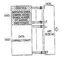
図4は、本発明の好適な第1の実施の形態による、制御情報とデータとが多重化されたシンボルブロック周期におけるFFTマッピングを示す。図4中、L個の変調シンボルにより構成された制御情報400が上記FFT404の入力インデックス0〜(L−1)の入力に印加され、データ402は、残りのFFT入力に印加される。すなわち、入力インデックスL〜(M−1)に印加される。ここで、制御情報400の変調シンボルがマッピングされる位置が、上記上位インデックス0〜(L−1)に限定されないことに留意しなければならない。すなわち、制御情報は、FFTのM個の入力タップのうち送信機と受信器とに既に知られているL個のタップにもマッピング可能である。
FIG. 4 shows an FFT mapping in a symbol block period in which control information and data are multiplexed according to the first preferred embodiment of the present invention. In FIG. 4, control
図5は、本発明の好適な第1の実施の形態による受信器の構造図である。 FIG. 5 is a structural diagram of a receiver according to the first preferred embodiment of the present invention.
図5を参照すると、上記受信器は、先ず、受信信号成分からCPを除去した後にFFT502を行い、上記FFT502からの出力からパイロットを取り出してチャンネル推定を行う。より具体的には、上記受信器のFFT502は、図3に示す送信部のIFFT314に対応して、上記FFT502に入力する受信信号500を周波数領域の信号に変換する。このとき、上記FFT502からの出力がパイロット510に該当する場合、上記FFT502からの出力は、チャンネル推定器504に入力される。すなわち、上記FFT502からの出力が生じるシンボルブロック周期が、図3に示すように、1つのTTI内における予め定められるパイロット周期である場合に、上記FFT502からの出力をパイロット510と見なす。
Referring to FIG. 5, the receiver first performs
上記チャンネル推定器504は、上記パイロット510からチャンネル状態を推定してチャンネル推定情報512を生成し、IFFT506においてデータ及び制御情報を復調可能に、上記チャンネル推定情報512を上記チャンネル補償ブロック524に渡す。その後、上記FFT502からの出力がデータ及び制御情報514を含むシンボルブロック周期、あるいはデータを含むシンボルブロック周期に該当する場合、上記FFT502からの出力は、上記チャンネル補償ブロック524により上記チャンネル推定情報512に基づいてチャンネル補償される。図示は省略するが、上記チャンネル推定器504においてパイロット510を取り出し、チャンネル補償ブロック524においてチャンネル補償動作を行うことは、上記IFFT506の出力端において行うことも可能である。
The
上記チャンネル補償の行われた信号526は、送信機に適用されたIFDMAあるいはLFDMAマッピングルールに基づいて上記IFFT506に入力した後、復調・復号が行われる。
The channel-compensated signal 526 is input to the
特に、制御情報とデータとを含むシンボルブロック周期の場合、送信機において、制御情報は、FFT404の入力インデックス0〜(L−1)に印加されて転送されるため、図5の上記IFFT506においては、出力インデックス0〜(L−1)の出力520を制御情報復調復号器508に印加することにより、制御情報を取り出すことが可能になる。そして、データの場合は、1シンボルブロック周期中に専らデータのみが転送される場合もあるため、上記IFFT506からの全ての出力、すなわち、出力インデックス0〜(M−1)からの出力518がデータ復調復号器522に印加される。上記制御情報に該当するシンボルブロック周期中に上記制御情報の復調・復号が行われて、送信機においてデータの転送時に用いられた変調及びコード方式、データ量、HARQ制御情報など516が上記データ復調復号器522に渡されると、最終的に復号されたデータが上記データ復調復号器522から出力される。
In particular, in the case of a symbol block period including control information and data, since the control information is applied to and transferred from the
図8は、本発明の好適な第1の実施の形態による受信器の動作を示すフローチャートである。 FIG. 8 is a flowchart showing the operation of the receiver according to the first preferred embodiment of the present invention.
ステップS800において、上記受信器は、受信信号成分からCPを除去した後にFFTを行い、上記FFT出力からパイロットを取り出してチャンネル推定を行う。ステップS802において、上記FFT出力が、データ及び制御情報を含むシンボルブロック周期、あるいは、データを含むシンボルブロック周期に該当する場合、上記FFT出力は、上記チャンネル補償ブロック524においてチャンネル補償が行われる。
In step S800, the receiver performs FFT after removing the CP from the received signal component, extracts a pilot from the FFT output, and performs channel estimation. In step S802, if the FFT output corresponds to a symbol block period including data and control information or a symbol block period including data, the
ステップS804において、上記チャンネル補償の行われた信号は、送信機に適用されたIFDMAあるいはLFDMAマッピングルールに基づいてIFFTに入力し、データ及び制御情報を含むシンボルブロック周期に該当するIFFT出力のうち制御情報に該当するインデックスの出力は、復調・復号によりデータに適用された変調及びコード、HARQ制御情報などを含む制御情報に変換される。 In step S804, the channel-compensated signal is input to the IFFT based on the IFDMA or LFDMA mapping rule applied to the transmitter, and is controlled among IFFT outputs corresponding to a symbol block period including data and control information. The output of the index corresponding to the information is converted into control information including modulation and code applied to the data by demodulation and decoding, HARQ control information, and the like.
ステップS806において、上記制御情報は、データ及び制御情報を含むシンボルブロック周期、あるいはデータのみを含むシンボル周期に該当するIFFT出力を復調・復号してデータを復元するのに用いられる。 In step S806, the control information is used to reconstruct data by demodulating and decoding an IFFT output corresponding to a symbol block period including data and control information or a symbol period including only data.
<第2の実施の形態>
図6は、本発明の好適な第2の実施の形態による制御情報とデータの多重化方法を示す。
<Second Embodiment>
FIG. 6 shows a method for multiplexing control information and data according to the second preferred embodiment of the present invention.
上記第1の実施の形態との違いは、制御情報602を1つのTTI600内の多数のシンボルブロック周期内に分散して転送するということである。すなわち、データと制御情報602とを各シンボルブロック周期604中に多重化するが、TTI600内の多数のシンボルブロック周期に分散して転送することにより、フェージングチャンネルから時間ダイバーシティゲインを得て制御情報の検出能を改善しているところに、第2の実施の形態の核心がある。図6において、データと制御情報とが多重化されたシンボルブロック周期中に、制御情報はK個のシンボルよりなり、データは(M−K)個のシンボルよりなり、上記制御情報及びデータはそれぞれFFT610の入力インデックス0〜(K−1)とK〜(M−1)とに印加される。上記K及びMの値は、それぞれ必要な制御情報の量及び転送すべきデータの量により決められる。
The difference from the first embodiment is that the
上記第1の実施の形態と同様に、上記制御情報602において、適用された変調及びコード方式、シンボルの総数、FFT610入力へのマッピングなどが送信機と受信器との間に予め定められているため、受信器は、所定の上記制御情報の転送フォーマットを基に制御情報の復調・復号を行うことができる。そして、上記第2の実施の形態においては、上記第1の実施の形態とは異なり、パイロットのオーバーヘッドを減らすために、パイロット606を1つのTTI内における第4のシンボルブロック周期中にのみ転送することができる。
Similar to the first embodiment, in the
このような送信信号は、第1の実施の形態と同様に、FFT610を介して適用されるIFDMAあるいはLFDMA技術によってIFFT入力にマッピング612された後、IFFT614により処理され、CPが付けられて転送される。上記送信信号を処理するための受信器の構造及び処理の手続きは、図5と図8に示す上記第1の実施の形態と基本的に同様である。上記第1の実施の形態とは異なり、第2の実施の形態においては、多数のシンボルブロック周期内に分散されて転送された制御情報のシンボルをいずれも受信し、復調・復号により制御情報を取得した後、データシンボルに対して復調・復号を行う。
Similar to the first embodiment, such a transmission signal is mapped 612 to the IFFT input by IFDMA or LFDMA technology applied via the
一方、上記第1の実施の形態による図8及び図9のフローチャートは、第2の実施の形態にも同様に適用可能である。 On the other hand, the flowcharts of FIGS. 8 and 9 according to the first embodiment are also applicable to the second embodiment.
図7は、本発明の好適な第1及び第2の実施の形態による受信部のIFFT出力が制御情報復調復号器とデータ復調復号器とにマッピングされる構造の一例を示す。 FIG. 7 shows an example of a structure in which the IFFT output of the receiving unit according to the first and second preferred embodiments of the present invention is mapped to the control information demodulation decoder and the data demodulation decoder.
図7に示すように、受信部のIFFT700において、インデックス0〜(K−1)とK〜(M−1)からの出力はそれぞれ制御情報復調復号器702とデータ復調復号器704とに印加され、各復調復号器702、704においては、制御情報とデータとの正常な復調・復号が可能になる。
As shown in FIG. 7, in
一方、本発明の詳細な説明の欄においては、その具体的な実施の形態について説明したが、本発明の範囲から逸脱しない限り、種々な変形が可能であることは言うまでもない。よって、本発明の範囲は、上述した実施の形態に限定されるものではなく、特許請求の範囲及びその均等物により定まるべきである。 On the other hand, in the detailed description section of the present invention, specific embodiments thereof have been described, but it goes without saying that various modifications are possible without departing from the scope of the present invention. Therefore, the scope of the present invention should not be limited to the above-described embodiments, but should be determined by the claims and their equivalents.
300:TTI
302:シンボルブロック周期
304:シンボルブロック生成部
306:データ
308:パイロット
310:FFT
312:IFDMA又はLFDMAマッピング
314:IFFT
300: TTI
302: Symbol block cycle 304: Symbol block generation unit 306: Data 308: Pilot 310: FFT
312: IFDMA or LFDMA mapping 314: IFFT
Claims (20)
複数のシンボルブロック周期よりなる1転送時間間隔(TTI)中に転送しようとする制御情報が存在する場合、前記TTI内における予め定められたシンボルブロック周期中に、前記制御情報と転送すべきデータとを含むシンボルブロックを生成するシンボルブロック生成部と、
前記シンボルブロックを高速フーリエ変換(FFT)するFFT部と、
前記FFT部からの信号を逆高速フーリエ変換(IFFT)して転送するIFFT部と、
を備えることを特徴とするデータ転送装置。 In a data transfer device of a frequency division multiple access based communication system,
When there is control information to be transferred in one transfer time interval (TTI) consisting of a plurality of symbol block periods, the control information and data to be transferred during a predetermined symbol block period in the TTI A symbol block generator for generating a symbol block including
An FFT unit for performing a fast Fourier transform (FFT) on the symbol block;
An IFFT unit for transferring the signal from the FFT unit by inverse fast Fourier transform (IFFT);
A data transfer device comprising:
複数のシンボル周期よりなる1転送時間間隔(TTI)中に転送しようとする制御情報が存在する場合、前記TTI内における予め定められたシンボル周期中に、前記制御情報と転送すべきデータとを含むシンボルブロックを生成するステップと、
前記シンボルブロックを高速フーリエ変換(FFT)するステップと、
前記FFTされた信号を逆高速フーリエ変換(IFFT)して転送するステップと、
を含むことを特徴とするデータ転送方法。 In a data transfer method for a communication system based on frequency division multiple access,
When control information to be transferred exists in one transfer time interval (TTI) composed of a plurality of symbol periods, the control information and data to be transferred are included in a predetermined symbol period in the TTI. Generating a symbol block;
Fast Fourier transform (FFT) the symbol block;
Transferring the FFTed signal by inverse fast Fourier transform (IFFT);
A data transfer method comprising:
1シンボルブロック周期中の受信信号が入力されて高速フーリエ変換(FFT)を行うFFT部と、
前記FFT部からの信号に対して逆高速フーリエ変換(IFFT)を行い、シンボルブロックを修復するIFFT部と、
前記シンボルブロック周期が、データと制御情報とを多重化する予め定められるシンボルブロック周期である場合、前記シンボルブロックのうち予め定められるIFFT出力インデックスに該当する変調シンボルを前記IFFT部から受け取り、復調・復号して制御情報を出力する制御情報復調復号部と、
前記制御情報を用いて、前記シンボルブロックのうち前記制御情報を除く残りのIFFT出力インデックスに該当する変調シンボルを前記IFFT部から受け取り、復調・復号してデータを出力するデータ復調復号部と、
を備えることを特徴とするデータ受信装置。 In a data receiver of a frequency division multiple access based communication system,
An FFT unit that receives a received signal in one symbol block period and performs a fast Fourier transform (FFT);
An IFFT unit that performs an inverse fast Fourier transform (IFFT) on the signal from the FFT unit to restore a symbol block;
When the symbol block period is a predetermined symbol block period for multiplexing data and control information, a modulation symbol corresponding to a predetermined IFFT output index among the symbol blocks is received from the IFFT unit, A control information demodulation / decoding unit for decoding and outputting control information;
A data demodulating / decoding unit that receives modulation symbols corresponding to the remaining IFFT output indexes excluding the control information in the symbol block from the IFFT unit using the control information;
A data receiving apparatus comprising:
前記チャンネル推定情報を用いて前記FFT部からのデータ及び制御情報を含むシンボルブロックをチャンネル補償した後、前記IFFT部に出力するチャンネル補償部と、
をさらに備えることを特徴とする請求項7に記載のデータ受信装置。 A channel estimator that generates channel estimation information using a pilot symbol from the FFT unit when the symbol block period is a predetermined symbol block period including a pilot;
A channel compensation unit for channel-compensating a symbol block including data and control information from the FFT unit using the channel estimation information, and then outputting to the IFFT unit;
The data receiving device according to claim 7, further comprising:
前記チャンネル推定情報を用いて前記FFT部からのデータ及び制御情報を含むシンボルブロックをチャンネル補償した後、前記IFFT部に出力するチャンネル補償部と、
をさらに備えることを特徴とする請求項7に記載のデータ受信装置。 A channel estimator that generates channel estimation information using a pilot symbol from the IFFT unit when the symbol block period is a predetermined symbol block period including a pilot;
A channel compensation unit for channel-compensating a symbol block including data and control information from the FFT unit using the channel estimation information, and then outputting to the IFFT unit;
The data receiving device according to claim 7, further comprising:
前記チャンネル推定情報を用いて前記IFFT部からのデータ及び制御情報を含むシンボルブロックをチャンネル補償した後、前記復調部に出力するチャンネル補償部と、
をさらに備えることを特徴とする請求項7に記載のデータ受信装置。 A channel estimator that generates channel estimation information using a pilot symbol from the IFFT unit when the symbol block period is a predetermined symbol block period including a pilot;
A channel compensation unit for channel-compensating a symbol block including data and control information from the IFFT unit using the channel estimation information, and then outputting to the demodulation unit;
The data receiving device according to claim 7, further comprising:
前記チャンネル推定情報を用いて前記FFT部からのデータ及び制御情報を含むシンボルブロックをチャンネル補償した後、前記復調部に出力するチャンネル補償部と、
をさらに備えることを特徴とする請求項7に記載のデータ受信装置。 A channel estimator that generates channel estimation information using a pilot symbol from the IFFT unit when the symbol block period is a predetermined symbol block period including a pilot;
A channel compensation unit for channel-compensating a symbol block including data and control information from the FFT unit using the channel estimation information and then outputting to the demodulation unit;
The data receiving device according to claim 7, further comprising:
1シンボルブロック周期中の受信信号が入力されて高速フーリエ変換(FFT)部により変換するステップと、
前記FFTされた信号を逆高速フーリエ変換(IFFT)部によりシンボルブロックとして修復するステップと、
前記シンボルブロック周期が、データと制御情報とを多重化する予め定められるシンボルブロック周期である場合、前記シンボルブロックのうち予め定められるIFFT出力インデックスに該当する変調シンボルを前記IFFT部から受け取り、復調・復号して制御情報を出力するステップと、
前記制御情報を用いて、前記シンボルブロックのうち前記制御情報を除く残りのIFFT出力インデックスに該当する変調シンボルを前記IFFT部から受け取り、復調・復号してデータを出力するステップと、
を含むことを特徴とするデータ受信方法。 In a data reception method for a communication system based on frequency division multiple access,
A received signal in one symbol block period is input and converted by a fast Fourier transform (FFT) unit;
Repairing the FFTed signal as a symbol block by an inverse fast Fourier transform (IFFT) unit;
When the symbol block period is a predetermined symbol block period for multiplexing data and control information, a modulation symbol corresponding to a predetermined IFFT output index among the symbol blocks is received from the IFFT unit, Decrypting and outputting control information;
Using the control information, receiving a modulation symbol corresponding to the remaining IFFT output index excluding the control information in the symbol block from the IFFT unit, demodulating and decoding, and outputting data;
A data receiving method comprising:
前記チャンネル推定情報を用いて前記FFT部からのデータ及び制御情報を含むシンボルブロックをチャンネル補償した後、前記IFFT部に出力するステップと、
をさらに含むことを特徴とする請求項14に記載のデータ受信方法。 When the symbol block period is a predetermined symbol block period including a pilot, generating channel estimation information using pilot symbols from the FFT unit;
After channel-compensating a symbol block including data and control information from the FFT unit using the channel estimation information, outputting to the IFFT unit;
The data receiving method according to claim 14, further comprising:
前記チャンネル推定情報を用いて前記FFT部からのデータ及び制御情報を含むシンボルブロックをチャンネル補償した後、前記IFFT部に出力するステップと、
をさらに含むことを特徴とする請求項14に記載のデータ受信方法。 When the symbol block period is a predetermined symbol block period including a pilot, generating channel estimation information using pilot symbols from the IFFT unit;
After channel-compensating a symbol block including data and control information from the FFT unit using the channel estimation information, outputting to the IFFT unit;
The data receiving method according to claim 14, further comprising:
前記チャンネル推定情報を用いて前記IFFT部からのデータ及び制御情報を含むシンボルブロックをチャンネル補償した後、前記復調部に出力するステップと、
をさらに含むことを特徴とする請求項14に記載のデータ受信方法。 When the symbol block period is a predetermined symbol block period including a pilot, generating channel estimation information using pilot symbols from the FFT unit;
After channel-compensating a symbol block including data and control information from the IFFT unit using the channel estimation information, outputting to the demodulation unit;
The data receiving method according to claim 14, further comprising:
前記チャンネル推定情報を用いて前記IFFT部からのデータ及び制御情報を含むシンボルブロックをチャンネル補償した後、前記復調部に出力するステップと、
をさらに含むことを特徴とする請求項14に記載のデータ受信方法。 When the symbol block period is a predetermined symbol block period including a pilot, generating channel estimation information using pilot symbols from the IFFT unit;
After channel-compensating a symbol block including data and control information from the IFFT unit using the channel estimation information, outputting to the demodulation unit;
The data receiving method according to claim 14, further comprising:
Applications Claiming Priority (1)
| Application Number | Priority Date | Filing Date | Title |
|---|---|---|---|
| KR1020050037294A KR100724949B1 (en) | 2005-05-03 | 2005-05-03 | Method and Apparatus for multiplexing data and control information in wireless communication systems based on frequency division multiple access |
Publications (2)
| Publication Number | Publication Date |
|---|---|
| JP2006314110A JP2006314110A (en) | 2006-11-16 |
| JP4319665B2 true JP4319665B2 (en) | 2009-08-26 |
Family
ID=36649568
Family Applications (1)
| Application Number | Title | Priority Date | Filing Date |
|---|---|---|---|
| JP2006129660A Active JP4319665B2 (en) | 2005-05-03 | 2006-05-08 | Method and apparatus for multiplexing data and control information in a radio communication system based on frequency division multiple access |
Country Status (15)
| Country | Link |
|---|---|
| US (4) | US7613245B2 (en) |
| EP (2) | EP1720310B1 (en) |
| JP (1) | JP4319665B2 (en) |
| KR (1) | KR100724949B1 (en) |
| CN (1) | CN1863181B (en) |
| AU (1) | AU2006201869B2 (en) |
| DK (2) | DK1720310T3 (en) |
| ES (2) | ES2879325T3 (en) |
| FI (1) | FI3454516T3 (en) |
| HU (1) | HUE055073T2 (en) |
| LT (1) | LT3454516T (en) |
| PL (2) | PL3454516T3 (en) |
| PT (2) | PT3454516T (en) |
| RU (1) | RU2320087C2 (en) |
| SI (2) | SI3454516T1 (en) |
Families Citing this family (61)
| Publication number | Priority date | Publication date | Assignee | Title |
|---|---|---|---|---|
| US8135088B2 (en) | 2005-03-07 | 2012-03-13 | Q1UALCOMM Incorporated | Pilot transmission and channel estimation for a communication system utilizing frequency division multiplexing |
| US7715460B2 (en) | 2005-04-22 | 2010-05-11 | Interdigital Technology Corporation | Hybrid orthogonal frequency division multiple access system and method |
| KR100724949B1 (en) * | 2005-05-03 | 2007-06-04 | 삼성전자주식회사 | Method and Apparatus for multiplexing data and control information in wireless communication systems based on frequency division multiple access |
| KR100790125B1 (en) * | 2005-06-22 | 2008-01-02 | 삼성전자주식회사 | Method and transmitting apparatus for allocating resourses for the uplink transmission in orthogonal frequency division multiplexing system |
| TW200733622A (en) * | 2006-01-17 | 2007-09-01 | Interdigital Tech Corp | Method and apparatus for mapping an uplink control channel to a physical channel in a single carrier frequency division multiple access system |
| US7623487B2 (en) * | 2006-05-24 | 2009-11-24 | Nortel Networks Limited | OFDM system and method for supporting a wide range of mobility speeds |
| US8374161B2 (en) * | 2006-07-07 | 2013-02-12 | Qualcomm Incorporated | Method and apparatus for sending data and control information in a wireless communication system |
| US9143288B2 (en) * | 2006-07-24 | 2015-09-22 | Qualcomm Incorporated | Variable control channel for a wireless communication system |
| US8929300B2 (en) | 2006-08-18 | 2015-01-06 | Panasonic Intellectual Property Corporation Of America | Radio communication base station device and control channel arranging method |
| US8363606B2 (en) * | 2006-09-05 | 2013-01-29 | Qualcomm Incorporated | Method and apparatus for data and control multiplexing |
| US7848446B2 (en) * | 2006-09-27 | 2010-12-07 | Telefonaktiebolaget L M Ericsson (Publ) | Reduction of peak-to-average-power ratio in a telecommunications system |
| EP2070246B1 (en) | 2006-10-04 | 2015-08-19 | Microsoft Technology Licensing, LLC | Method for multiplexing control and data channel |
| WO2008047874A1 (en) * | 2006-10-19 | 2008-04-24 | Nec Corporation | Signal generation device, method, and its program in radio transmission system |
| CA2665682C (en) * | 2006-10-31 | 2016-10-25 | Qualcomm Incorporated | Method and apparatus for increasing ack resources for a wireless communication system |
| ATE544256T1 (en) * | 2006-11-01 | 2012-02-15 | Qualcomm Inc | CONTROL AND DATA MULTIPLEXING WITH VARIABLE POWER OFFSET IN AN SC-FDMA SYSTEM |
| KR101288215B1 (en) * | 2006-11-17 | 2013-07-18 | 삼성전자주식회사 | Method and apparayus for transmitting and reseiving data in mobile commuication system |
| JP4930006B2 (en) * | 2006-11-22 | 2012-05-09 | 日本電気株式会社 | Mobile communication apparatus, mobile communication system, and power consumption reduction method used therefor |
| US8954105B2 (en) | 2006-12-18 | 2015-02-10 | Samsung Electronics Co., Ltd. | Method and apparatus for transmitting/receiving data and control information through an uplink in a wireless communication system |
| KR101351020B1 (en) * | 2007-01-04 | 2014-01-16 | 엘지전자 주식회사 | Method for multiplexing control signal in the mobile communication system |
| US8223854B2 (en) * | 2007-01-10 | 2012-07-17 | Motorola Mobility, Inc. | Method and apparatus for transmission of uplink control signaling and user data in a single carrier orthogonal frequency division multiplexing communication system |
| KR101372927B1 (en) | 2007-01-22 | 2014-03-12 | 삼성전자주식회사 | Digital broadcasting receiver and channel tuning method thereof |
| KR100987266B1 (en) * | 2007-02-14 | 2010-10-12 | 삼성전자주식회사 | Method and apparatus for transmitting and receiving control information of single carrier-frequency division multiple access system |
| KR101206118B1 (en) * | 2007-03-14 | 2012-11-29 | 인터디지탈 테크날러지 코포레이션 | Transmission of ack/nack and transmit power control feedback in evolved utra |
| WO2008120925A1 (en) * | 2007-03-29 | 2008-10-09 | Lg Electronics Inc. | Method of transmitting sounding reference signal in wireless communication system |
| US8331328B2 (en) | 2007-06-08 | 2012-12-11 | Samsung Electronic Co., Ltd | Control and data signaling in SC-FDMA communication systems |
| KR100956494B1 (en) | 2007-06-14 | 2010-05-07 | 엘지전자 주식회사 | Method for transmitting control signal |
| JP4916389B2 (en) | 2007-06-19 | 2012-04-11 | 株式会社エヌ・ティ・ティ・ドコモ | Wireless communication control method, base station apparatus, and user apparatus |
| KR101380558B1 (en) | 2007-06-19 | 2014-04-02 | 엘지전자 주식회사 | Method of Transmitting Sounding Reference Signal |
| PL2192714T3 (en) * | 2007-07-06 | 2016-02-29 | Huawei Tech Co Ltd | HARQ communication method, system, base station apparatus, and mobile station apparatus thereof |
| US8467367B2 (en) * | 2007-08-06 | 2013-06-18 | Qualcomm Incorporated | Multiplexing and transmission of traffic data and control information in a wireless communication system |
| KR101430267B1 (en) | 2007-08-14 | 2014-08-18 | 엘지전자 주식회사 | Method of Transmitting Data in a Wireless Communication System |
| KR100913106B1 (en) | 2007-08-14 | 2009-08-21 | 엘지전자 주식회사 | Method For Acquiring Resource Region Information For PHICH and Method of Receiving PDCCH |
| KR101507785B1 (en) | 2007-08-16 | 2015-04-03 | 엘지전자 주식회사 | A method for transmitting channel quality information in a MIMO (Multiple Input Multiple Output) system |
| KR101405974B1 (en) | 2007-08-16 | 2014-06-27 | 엘지전자 주식회사 | Methods for transmitting codewords in multiple input multiple output system |
| KR101792110B1 (en) | 2007-09-12 | 2017-11-02 | 애플 인크. | Systems and methods for uplink signalling |
| KR101531416B1 (en) | 2007-09-13 | 2015-06-24 | 옵티스 셀룰러 테크놀로지, 엘엘씨 | Method For Transmitting Uplink Signals |
| US7970067B1 (en) * | 2007-10-31 | 2011-06-28 | Samsung Electronics Co., Ltd. | OFDM receiver and method for enhancing channel estimation performance in communication environment where high doppler frequency exists |
| EP2383920B1 (en) | 2007-12-20 | 2014-07-30 | Optis Wireless Technology, LLC | Control channel signaling using a common signaling field for transport format and redundancy version |
| JP5061892B2 (en) * | 2007-12-28 | 2012-10-31 | 富士通株式会社 | Signal multiplexing method, transmitting station and receiving station in radio communication system |
| US8451778B2 (en) * | 2008-04-30 | 2013-05-28 | Lg Electronics Inc. | Method and apparatus for transmitting control signal in radio communication system |
| US8634333B2 (en) | 2008-05-07 | 2014-01-21 | Qualcomm Incorporated | Bundling of ACK information in a wireless communication system |
| KR101441147B1 (en) | 2008-08-12 | 2014-09-18 | 엘지전자 주식회사 | Method of transmitting sr in wireless communication system |
| US8121232B2 (en) | 2008-11-06 | 2012-02-21 | Lg Electronics Inc. | Transmitting/receiving system and method of processing broadcast signal in transmitting/receiving system |
| US20100120442A1 (en) * | 2008-11-12 | 2010-05-13 | Motorola, Inc. | Resource sharing in relay operations within wireless communication systems |
| KR101587281B1 (en) * | 2009-03-12 | 2016-01-20 | 삼성전자주식회사 | Method for encoding contorl information in a communication system and transmission/reception method and apparatus thereof |
| CN102077627B (en) * | 2009-04-30 | 2013-03-27 | 华为技术有限公司 | Uplink signal processing method, base station and user terminal |
| KR101784189B1 (en) * | 2009-10-28 | 2017-10-12 | 엘지전자 주식회사 | Method and appratus for transmitting uplink control information in multiple-carrier system |
| US9094083B2 (en) * | 2010-05-18 | 2015-07-28 | Qualcomm Incorporated | Systems, apparatus and methods to facilitate efficient repeater usage |
| US8705399B2 (en) | 2010-10-29 | 2014-04-22 | Neocific, Inc. | Transmission of synchronization and control signals in a broadband wireless system |
| KR101452022B1 (en) * | 2010-11-09 | 2014-10-23 | 한국전자통신연구원 | Receiving device and method for providing input bits of the Fast Fourier Transformer depending on the modulation |
| JP6465810B2 (en) * | 2012-12-21 | 2019-02-06 | サムスン エレクトロニクス カンパニー リミテッド | Signal transmission / reception method and apparatus using multiple modulation techniques in wireless communication system |
| US10826663B2 (en) * | 2013-03-13 | 2020-11-03 | Huawei Technologies Co., Ltd. | System and method for determining a pilot signal |
| US9716573B2 (en) | 2014-06-13 | 2017-07-25 | Futurewei Technologies, Inc. | Aggregated touchless wireless fronthaul |
| US10404441B2 (en) | 2014-11-11 | 2019-09-03 | Electronics And Telecommunications Research Institute | Method and apparatus for configuring transmission time interval in mobile communication system |
| US9755779B2 (en) * | 2015-04-17 | 2017-09-05 | Futurewei Technologies, Inc. | Digital representations of analog signals and control words using different multi-level modulation formats |
| US10868650B2 (en) * | 2015-05-27 | 2020-12-15 | Qualcomm Incorporated | Pilot reconfiguration and retransmission in wireless networks |
| US10027413B2 (en) | 2015-06-18 | 2018-07-17 | Futurewei Technologies, Inc. | Cascaded waveform modulation with an embedded control signal for high-performance mobile fronthaul |
| MX2019001310A (en) | 2016-08-01 | 2019-10-07 | Nokia Technologies Oy | On the usage of control resources for data transmission. |
| RU2684636C1 (en) * | 2018-05-25 | 2019-04-11 | Общество с ограниченной ответственностью "НИРИТ-СИНВЭЙ Телеком Технолоджи" | Method of data transmission based on ofdm signals |
| EP3591919A1 (en) * | 2018-07-05 | 2020-01-08 | Nxp B.V. | Signal communication with decoding window |
| US11689343B2 (en) * | 2020-04-15 | 2023-06-27 | Qualcomm Incorporated | Peak suppression information multiplexing on downlink shared channel |
Family Cites Families (38)
| Publication number | Priority date | Publication date | Assignee | Title |
|---|---|---|---|---|
| US5659569A (en) | 1990-06-25 | 1997-08-19 | Qualcomm Incorporated | Data burst randomizer |
| US5151919A (en) | 1990-12-17 | 1992-09-29 | Ericsson-Ge Mobile Communications Holding Inc. | Cdma subtractive demodulation |
| US5396516A (en) | 1993-02-22 | 1995-03-07 | Qualcomm Incorporated | Method and system for the dynamic modification of control paremeters in a transmitter power control system |
| US5790551A (en) | 1995-11-28 | 1998-08-04 | At&T Wireless Services Inc. | Packet data transmission using dynamic channel assignment |
| DE19617293A1 (en) * | 1996-04-30 | 1997-11-20 | Bosch Gmbh Robert | Process for setting up a transport data stream |
| US5859840A (en) | 1996-05-31 | 1999-01-12 | Qualcomm Incorporated | Spread spectrum communication system which defines channel groups comprising selected channels that are additional to a primary channel and transmits group messages during call set up |
| JP3254390B2 (en) | 1996-10-18 | 2002-02-04 | 三菱電機株式会社 | Transmission power control device |
| US6335922B1 (en) | 1997-02-11 | 2002-01-01 | Qualcomm Incorporated | Method and apparatus for forward link rate scheduling |
| WO1999001956A1 (en) | 1997-07-01 | 1999-01-14 | Advanced Digital Television Broadcasting Laboratory | Orthogonal frequency-division multiplex transmission system, and its transmitter and receiver |
| US6529492B1 (en) * | 1997-12-30 | 2003-03-04 | Matsushita Electric Industrial Co., Ltd. | CDMA radio multiplex transmitting device and a CDMA radio multiplex receiving device |
| US6356569B1 (en) * | 1997-12-31 | 2002-03-12 | At&T Corp | Digital channelizer with arbitrary output sampling frequency |
| EP0967763B1 (en) * | 1998-06-29 | 2004-12-01 | Alcatel | Multicarrier receiver with per-carrier RLS frequency domain equalisation |
| JP3812203B2 (en) | 1999-02-17 | 2006-08-23 | 三菱電機株式会社 | Waveguide slot array antenna |
| EP1079576A3 (en) * | 1999-08-25 | 2003-05-07 | Matsushita Electric Industrial Co., Ltd. | Multicarrier receiver with direct extraction of a control signal |
| US6798791B1 (en) | 1999-12-16 | 2004-09-28 | Agere Systems Inc | Cluster frame synchronization scheme for a satellite digital audio radio system |
| KR100748490B1 (en) * | 2000-01-28 | 2007-08-13 | 엘지전자 주식회사 | Tps extraction apparatus for dvb-t system |
| WO2002005467A1 (en) * | 2000-07-10 | 2002-01-17 | Matsushita Electric Industrial Co., Ltd. | Multi-carrier communication device and peak power suppressing method |
| KR100781969B1 (en) * | 2001-03-26 | 2007-12-06 | 삼성전자주식회사 | Data communication apparatus and method based on the Orthogonal Frequency Division Multiple Access |
| KR100375350B1 (en) * | 2001-03-26 | 2003-03-08 | 삼성전자주식회사 | Data communication apparatus and method based on the Orthogonal Frequency Division Multiple Access |
| DE10115221A1 (en) * | 2001-03-28 | 2002-10-10 | Bosch Gmbh Robert | Method for frame and frequency synchronization of an OFDM signal and method for transmitting an OFDM signal |
| CN1159911C (en) * | 2002-02-01 | 2004-07-28 | 清华大学 | Time-domain synchronous orthogonal frequency division multiplex modulation method of low peak average power ratio |
| JP2003309533A (en) * | 2002-04-17 | 2003-10-31 | Matsushita Electric Ind Co Ltd | Wireless transmitter, wireless receiver, and method thereof |
| KR100770912B1 (en) * | 2003-06-16 | 2007-10-26 | 삼성전자주식회사 | Apparatus for generating preamble sequences in communication system using orthogonal frequency division multiplexing scheme and method thereof |
| WO2005015775A1 (en) * | 2003-08-11 | 2005-02-17 | Nortel Networks Limited | System and method for embedding ofdm in cdma systems |
| KR100511554B1 (en) * | 2003-09-02 | 2005-08-31 | 한국전자통신연구원 | Method for comprising and assigning forwarding channel on orthogonal frequency division multiple access frequency division duplex |
| US7221680B2 (en) * | 2003-09-02 | 2007-05-22 | Qualcomm Incorporated | Multiplexing and transmission of multiple data streams in a wireless multi-carrier communication system |
| EP1521413A3 (en) * | 2003-10-01 | 2009-09-30 | Panasonic Corporation | Multicarrier reception with channel estimation and equalisation |
| JP3877215B2 (en) * | 2003-10-10 | 2007-02-07 | 株式会社インテリジェント・コスモス研究機構 | Transmission device, communication system, and communication method |
| US8526412B2 (en) * | 2003-10-24 | 2013-09-03 | Qualcomm Incorporated | Frequency division multiplexing of multiple data streams in a wireless multi-carrier communication system |
| KR100891806B1 (en) * | 2003-11-26 | 2009-04-07 | 삼성전자주식회사 | Apparatus for channel allocaction adaptively by channel estimation in orthogonal frequency division multiple access system and the method thereof |
| US8135088B2 (en) | 2005-03-07 | 2012-03-13 | Q1UALCOMM Incorporated | Pilot transmission and channel estimation for a communication system utilizing frequency division multiplexing |
| US8031583B2 (en) * | 2005-03-30 | 2011-10-04 | Motorola Mobility, Inc. | Method and apparatus for reducing round trip latency and overhead within a communication system |
| KR100724949B1 (en) * | 2005-05-03 | 2007-06-04 | 삼성전자주식회사 | Method and Apparatus for multiplexing data and control information in wireless communication systems based on frequency division multiple access |
| US8019006B2 (en) * | 2005-05-19 | 2011-09-13 | Samsung Electronics Co., Ltd. | Apparatus and method for FT pre-coding of data and control signals to reduce PAPR in a multi-carrier wireless network |
| JP4432933B2 (en) * | 2005-07-08 | 2010-03-17 | セイコーエプソン株式会社 | Image display device and image display method |
| TW200733622A (en) * | 2006-01-17 | 2007-09-01 | Interdigital Tech Corp | Method and apparatus for mapping an uplink control channel to a physical channel in a single carrier frequency division multiple access system |
| US20070189151A1 (en) * | 2006-02-10 | 2007-08-16 | Interdigital Technology Corporation | Method and apparatus for performing uplink transmission in a multiple-input multiple-output single carrier frequency division multiple access system |
| JP5121404B2 (en) * | 2006-11-15 | 2013-01-16 | パナソニック株式会社 | Semiconductor device for spread spectrum radar apparatus |
-
2005
- 2005-05-03 KR KR1020050037294A patent/KR100724949B1/en active IP Right Grant
-
2006
- 2006-05-03 ES ES06009140T patent/ES2879325T3/en active Active
- 2006-05-03 SI SI200632433T patent/SI3454516T1/en unknown
- 2006-05-03 LT LTEP18191168.6T patent/LT3454516T/en unknown
- 2006-05-03 DK DK06009140.2T patent/DK1720310T3/en active
- 2006-05-03 PT PT181911686T patent/PT3454516T/en unknown
- 2006-05-03 FI FIEP18191168.6T patent/FI3454516T3/en active
- 2006-05-03 PT PT60091402T patent/PT1720310T/en unknown
- 2006-05-03 HU HUE06009140A patent/HUE055073T2/en unknown
- 2006-05-03 SI SI200632405T patent/SI1720310T1/en unknown
- 2006-05-03 EP EP06009140.2A patent/EP1720310B1/en active Active
- 2006-05-03 EP EP18191168.6A patent/EP3454516B1/en active Active
- 2006-05-03 PL PL18191168.6T patent/PL3454516T3/en unknown
- 2006-05-03 DK DK18191168.6T patent/DK3454516T3/en active
- 2006-05-03 RU RU2006115276/09A patent/RU2320087C2/en active
- 2006-05-03 US US11/416,393 patent/US7613245B2/en active Active
- 2006-05-03 PL PL06009140T patent/PL1720310T3/en unknown
- 2006-05-03 AU AU2006201869A patent/AU2006201869B2/en active Active
- 2006-05-03 ES ES18191168T patent/ES2958746T3/en active Active
- 2006-05-08 CN CN2006100841587A patent/CN1863181B/en active Active
- 2006-05-08 JP JP2006129660A patent/JP4319665B2/en active Active
-
2009
- 2009-06-09 US US12/481,337 patent/US7697631B2/en active Active
-
2010
- 2010-03-08 US US12/661,001 patent/US7929590B2/en active Active
-
2011
- 2011-03-11 US US13/046,633 patent/US8571122B2/en active Active
Also Published As
Similar Documents
| Publication | Publication Date | Title |
|---|---|---|
| JP4319665B2 (en) | Method and apparatus for multiplexing data and control information in a radio communication system based on frequency division multiple access | |
| AU2004247167B2 (en) | Apparatus and method for transmitting and receiving a pilot pattern for identification of a base station in an OFDM communication system | |
| KR101564479B1 (en) | Method and system for reduced complexity channel estimation and interference cancellation for v-mimo demodulation | |
| JP4515501B2 (en) | Apparatus and method for transmitting and receiving pilot signal in communication system using orthogonal frequency division multiple system | |
| US8576935B2 (en) | Adaptive pilot structure to assist channel estimation in spread spectrum systems | |
| US20090245399A1 (en) | Method and apparatus for inserting guard interval in a mobile communication system | |
| EP1740008A1 (en) | Downlink soft handover in an OFDM system | |
| US20110211544A1 (en) | Transmission apparatus, transmission method, reception apparatus and reception method | |
| KR20060136290A (en) | Method and apparatus for transceiving downlink data to combining receive data in ofdm system | |
| KR20100133497A (en) | Method and system for providing an uplink structure and minimizing pilot signal overhead in a wireless communication network | |
| US20040258014A1 (en) | Apparatus and method for assigning a dedicated pilot channel for identification of a base station in an OFDM communication system | |
| US20040257981A1 (en) | Apparatus and method for transmitting and receiving pilot patterns for identifying base stations in an OFDM communication system | |
| EP1679850A2 (en) | Pilot-based channel estimation method for mc-cdma system | |
| EP1777869A1 (en) | Apparatus and method for channel scheduling in an OFDM system | |
| EP1999859B1 (en) | Apparatus and method for efficiently transmitting/receiving a control channel in a mobile communication system simultaneously supporting a synchronous hrpd system and an ofdm system | |
| WO2009060324A1 (en) | System and method of selectively communicating using ofdm transmissions and single-carrier block transmissions |
Legal Events
| Date | Code | Title | Description |
|---|---|---|---|
| A977 | Report on retrieval |
Free format text: JAPANESE INTERMEDIATE CODE: A971007 Effective date: 20081125 |
|
| A131 | Notification of reasons for refusal |
Free format text: JAPANESE INTERMEDIATE CODE: A131 Effective date: 20081209 |
|
| TRDD | Decision of grant or rejection written | ||
| A01 | Written decision to grant a patent or to grant a registration (utility model) |
Free format text: JAPANESE INTERMEDIATE CODE: A01 Effective date: 20090507 |
|
| A01 | Written decision to grant a patent or to grant a registration (utility model) |
Free format text: JAPANESE INTERMEDIATE CODE: A01 |
|
| A61 | First payment of annual fees (during grant procedure) |
Free format text: JAPANESE INTERMEDIATE CODE: A61 Effective date: 20090528 |
|
| FPAY | Renewal fee payment (event date is renewal date of database) |
Free format text: PAYMENT UNTIL: 20120605 Year of fee payment: 3 |
|
| R150 | Certificate of patent or registration of utility model |
Ref document number: 4319665 Country of ref document: JP Free format text: JAPANESE INTERMEDIATE CODE: R150 Free format text: JAPANESE INTERMEDIATE CODE: R150 |
|
| S111 | Request for change of ownership or part of ownership |
Free format text: JAPANESE INTERMEDIATE CODE: R313113 |
|
| FPAY | Renewal fee payment (event date is renewal date of database) |
Free format text: PAYMENT UNTIL: 20120605 Year of fee payment: 3 |
|
| R350 | Written notification of registration of transfer |
Free format text: JAPANESE INTERMEDIATE CODE: R350 |
|
| FPAY | Renewal fee payment (event date is renewal date of database) |
Free format text: PAYMENT UNTIL: 20120605 Year of fee payment: 3 |
|
| FPAY | Renewal fee payment (event date is renewal date of database) |
Free format text: PAYMENT UNTIL: 20130605 Year of fee payment: 4 |
|
| R250 | Receipt of annual fees |
Free format text: JAPANESE INTERMEDIATE CODE: R250 |
|
| R250 | Receipt of annual fees |
Free format text: JAPANESE INTERMEDIATE CODE: R250 |
|
| R250 | Receipt of annual fees |
Free format text: JAPANESE INTERMEDIATE CODE: R250 |
|
| R250 | Receipt of annual fees |
Free format text: JAPANESE INTERMEDIATE CODE: R250 |
|
| R250 | Receipt of annual fees |
Free format text: JAPANESE INTERMEDIATE CODE: R250 |
|
| R250 | Receipt of annual fees |
Free format text: JAPANESE INTERMEDIATE CODE: R250 |
|
| R250 | Receipt of annual fees |
Free format text: JAPANESE INTERMEDIATE CODE: R250 |
|
| R250 | Receipt of annual fees |
Free format text: JAPANESE INTERMEDIATE CODE: R250 |
|
| R250 | Receipt of annual fees |
Free format text: JAPANESE INTERMEDIATE CODE: R250 |
|
| R250 | Receipt of annual fees |
Free format text: JAPANESE INTERMEDIATE CODE: R250 |
|
| R250 | Receipt of annual fees |
Free format text: JAPANESE INTERMEDIATE CODE: R250 |
|
| R250 | Receipt of annual fees |
Free format text: JAPANESE INTERMEDIATE CODE: R250 |