JP4319657B2 - Piezoelectric vibrator - Google Patents
Piezoelectric vibrator Download PDFInfo
- Publication number
- JP4319657B2 JP4319657B2 JP2006020862A JP2006020862A JP4319657B2 JP 4319657 B2 JP4319657 B2 JP 4319657B2 JP 2006020862 A JP2006020862 A JP 2006020862A JP 2006020862 A JP2006020862 A JP 2006020862A JP 4319657 B2 JP4319657 B2 JP 4319657B2
- Authority
- JP
- Japan
- Prior art keywords
- vibrating arm
- end side
- tuning fork
- groove
- hole
- Prior art date
- Legal status (The legal status is an assumption and is not a legal conclusion. Google has not performed a legal analysis and makes no representation as to the accuracy of the status listed.)
- Expired - Fee Related
Links
Images


Description
本発明は基部に振動腕部が伸び出した構造の圧電振動子に関する。 The present invention relates to a piezoelectric vibrator having a structure in which a vibrating arm portion extends from a base portion.
この種の圧電振動子例えば音叉型の水晶振動子は一般に腕時計の歩度を刻む信号源として周知され、近年では携帯型の電子機器に同期信号源として採用されている。このようなものでは電子機器の小型化に対応してさらに小さな水晶振動子が求められている。 This type of piezoelectric vibrator, for example, a tuning-fork type quartz vibrator, is generally known as a signal source for engraving the rate of a wristwatch, and has recently been adopted as a synchronization signal source in portable electronic devices. In such a case, there is a demand for a smaller crystal resonator corresponding to the downsizing of electronic equipment.
音叉型水晶振動子の構成については例えば特許文献1に記載されている。その構成を図10に示すと音叉型の水晶振動子は基部1に一対の振動腕部である音叉腕2a及び2bが設けられ各音叉腕2a,2bにおける両主面には溝部3が設けられている。当該溝部3及び各音叉腕2a,2bの両側面には、各音叉腕2a,2bの屈曲振動に基づいた音叉振動を励起するための励振電極5が設けられている。当該音叉型振動子に電荷を与えた際に一方の音叉腕2aの側面及び他方の音叉腕2bの溝部3内が同電位となり、他方の音叉腕2bの側面及び一方の音叉腕2aの溝部3内が逆電位となるように励振電極5は結線されている。
The configuration of the tuning fork type crystal resonator is described in
このような音叉型水晶振動子によれば溝部3を形成しない場合に比較して、X軸方向(音叉腕の幅方向)での電界強度が増して各音叉腕2a,2bの両側面間で互いに逆方向に伸縮するY軸方向(音叉腕の長さ方向)での屈曲振動が強励振される。
According to such a tuning fork type crystal resonator, the electric field strength in the X-axis direction (tuning fork arm width direction) is increased as compared with the case where the
このように構成することにより音叉腕2a,2bの振動損失が低くなり基本的にCI(クリスタルインピーダンス)値が良好な圧電振動子を得ることができる。
With this configuration, the vibration loss of the
しかしながら当該水晶振動子を利用した電子部品における消費電力の省電力化の要請から更なるCI値の低下が求められている。また前記特許文献1記載の音叉型水晶振動子は既述のように音叉腕に溝部が設けられているため当該水晶振動子を小型化した場合に耐衝撃性が小さくなり、落下などの耐衝撃性が低く電子部品などを製造する際に破損等の不具合が発生するおそれがあった。
However, there is a demand for further reduction in the CI value in response to a request for power saving in electronic components using the crystal resonator. Since the tuning fork type crystal resonator described in
本発明は、このような問題を解決するためになされたものであって、その目的とするところは、振動腕部を供えた圧電振動子についてCI値を小さくするところにある。また他の目的は腕部を備えた圧電振動子について衝撃性を向上させることにある。 The present invention has been made to solve such a problem, and an object thereof is to reduce the CI value of a piezoelectric vibrator provided with a vibrating arm portion. Another object is to improve impact characteristics of a piezoelectric vibrator having an arm portion.
本発明は、基部から振動腕部が2本伸びだして音叉型に形成され、振動腕部の表面部及び裏面部の少なくとも一方に、当該振動腕部の基端部側から長さ方向に沿って形成された溝部を備えた圧電振動子において、
前記振動腕部の基端部に位置する溝部の中に設けられ、振動腕部の表面部及び裏面部間を貫通する貫通孔と、
この貫通孔内に形成され、貫通孔が開いている溝部内に形成された電極と同電位である電極と、を備え、
圧電振動子における振動腕部の先端側及びその反対側を夫々一端側及び他端側とすると、前記溝部の他端が2本の振動腕部の間における基端部分である音叉股部よりも前記他端側に位置すると共に、前記貫通孔の一端及び他端が夫々前記音叉股部よりも前記一端側及び他端側に位置することを特徴とする。
In the present invention, two vibrating arm portions are extended from the base portion to form a tuning fork type, and at least one of the front surface portion and the back surface portion of the vibrating arm portion is extended along the length direction from the proximal end side of the vibrating arm portion. In a piezoelectric vibrator having a groove formed by
A through-hole provided in a groove located at the base end of the vibrating arm and penetrating between a front surface and a back surface of the vibrating arm;
An electrode that is formed in the through hole and has the same potential as the electrode formed in the groove portion in which the through hole is open ,
When the distal end side and the opposite side of the vibrating arm portion in the piezoelectric vibrator are respectively one end side and the other end side, the other end of the groove portion is more than the tuning fork crotch portion that is the base end portion between the two vibrating arm portions. It is located on the other end side, and one end and the other end of the through hole are located on the one end side and the other end side, respectively, with respect to the tuning fork crotch portion .
他の発明は、基部から振動腕部2本伸びだして音叉型に形成された圧電振動子において、
振動腕部の表面部及び裏面部の少なくとも一方に、当該振動腕部の基端部側から長さ方向に沿って形成されかつ各々長さ方向に沿って分割された複数の溝部と、
前記振動腕部の基端部に位置する溝部の中に設けられ、振動腕部の表面部及び裏面部間を貫通する貫通孔と、
この貫通孔内に形成され、貫通孔が開いている溝部内に形成された電極と同電位である電極と、を備え、
圧電振動子における振動腕部の先端側及びその反対側を夫々一端側及び他端側とすると、前記溝部の他端が2本の振動腕部の間における基端部分である音叉股部よりも前記他端側に位置すると共に、前記貫通孔の一端及び他端が夫々前記音叉股部よりも前記一端側及び他端側に位置することを特徴とする。
Another invention is a piezoelectric vibrator formed in a tuning fork shape by extending two vibrating arms from a base,
A plurality of groove portions formed along the length direction from the base end side of the vibration arm portion and divided along the length direction on at least one of the front surface portion and the back surface portion of the vibration arm portion;
A through-hole provided in a groove located at the base end of the vibrating arm and penetrating between a front surface and a back surface of the vibrating arm;
An electrode that is formed in the through hole and has the same potential as the electrode formed in the groove portion in which the through hole is open ,
When the distal end side and the opposite side of the vibrating arm portion in the piezoelectric vibrator are respectively one end side and the other end side, the other end of the groove portion is more than the tuning fork crotch portion that is the base end portion between the two vibrating arm portions. It is located on the other end side, and one end and the other end of the through hole are located on the one end side and the other end side, respectively, with respect to the tuning fork crotch portion .
本発明は、振動腕部の基端部に位置する溝部の中に貫通孔を設け、この貫通孔内にも電極を設けた構成としている。振動腕部を振動させる力は主に溝部内の電極と振動腕部の側面の電極との間の電気力線により生じるが、電気力線による振動腕部を振動させる作用は、振動腕部の根元(基端部)が大きい。従って振動腕部の基端部に貫通孔を開けてここに電極を設けるようにすれば、基端部の電気力線が増えて効率よく振動することになる。このため圧電振動子のクリスタルインピーダンス(CI値)が小さくなり、消費電力を抑えることができる。 In the present invention, a through hole is provided in a groove located at the base end portion of the vibrating arm portion, and an electrode is also provided in the through hole. The force that vibrates the vibrating arm is mainly generated by the electric lines of force between the electrode in the groove and the side electrode of the vibrating arm, but the action of vibrating the vibrating arm by the electric lines of force The root (base end) is large. Therefore, if a through hole is formed in the base end portion of the vibrating arm portion and an electrode is provided here, the electric lines of force at the base end portion are increased and the vibration is efficiently performed. For this reason, the crystal impedance (CI value) of the piezoelectric vibrator is reduced, and power consumption can be suppressed .
(第1の実施の形態)
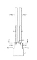
図1は、本発明の圧電振動子を音叉型の水晶振動子に適用した実施の形態を示す図である。この水晶振動子における水晶振動子本体(水晶片)は、両側部の上部側が矩形に切り欠かれた切り欠き部11を備えた概ね角型の基部1と、この基部1の上端側から各々互いに間隔をおいて平行に伸びだした2本の(一対の)振動腕部2(2a、2b)とを備えていて全体の形状が音叉型の水晶片として構成されている。更に振動腕部2(2a、2b)の表面部及び裏面部には、各々当該振動腕部2(2a、2b)の基端部から先端側に向けて溝部3が形成されていると共に、前記基端部に位置する溝部3の中には、振動腕部の2(2a、2b)の両主面間を貫通する、即ち表面部及び裏面部間を貫通する例えば角型の貫通孔4(4a、4b)が形成されている。図1では、貫通孔4は、溝部3よりも少し狭く記載してあるが、例えば一辺が溝部3の幅に相当する長さの正方形状に形成してもよい。
(First embodiment)
FIG. 1 is a diagram showing an embodiment in which a piezoelectric vibrator of the present invention is applied to a tuning fork type crystal vibrator. A crystal resonator body (crystal piece) in this crystal resonator includes a substantially
一対の振動腕部2a、2bの間における基部1の平面形状は湾曲しており、各溝部3は、この湾曲部(音叉又部)の最下部(振動腕部2の先端側を上方としている)20よりも基部1の下方側に少し食い込んで形成されており、貫通孔4の下端は、前記最下部20と同じ高さレベルに位置している。
The planar shape of the
ここで図2を参照しながら励振電極及び引き出し電極に関して述べると、この水晶振動子には、一対をなす一方の電極と他方の電極とが存在する。先ず振動腕部2aに着目すると、振動腕部2aの溝部3の内面全体及び当該溝部3内の貫通孔4aの内面全体に亘って一方の励振電極51が形成されていると共に、この振動腕部2aの両側面21、21、及び主面22、22(表面部及び裏面部)における溝部3よりも上方部位には他方の励振電極61が形成されている。なお図2において励振電極51は、図面を見やすくするために斜線と黒の点在領域とを使い分けて表している。
Here, the excitation electrode and the extraction electrode will be described with reference to FIG. 2. In this crystal resonator, one electrode and the other electrode forming a pair exist. First, paying attention to the vibrating
また振動腕部2bに着目すると、振動腕部2bの溝部3の内面全体及び当該溝部3内の貫通孔4bの内面全体に亘って他方の励振電極61が形成されていると共にこの振動腕部2bの両側面21、21、及び主面22、22(表面部及び裏面部)における溝部3よりも上方部位には一方の励振電極51が形成されている。そしてこれら一方の励振電極51同士が電気的に接続されるように基部1の表面に引き出し電極52からなるパターンが形成されていると共に、他方の励振電極61同士が電気的に接続されるように基部1の表面に引き出し電極62からなるパターンが形成されている。
Focusing on the vibrating
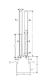
この水晶振動子の各部位の寸法を図3を参照しながら示すと、振動腕部2(2a、2b)の長さL1は例えば1650μmであり、溝部3の長さL2は例えば847μmであり、基部1の底面から音叉又部の最下部20までの長さL3は例えば600μmである。また振動腕部2(2a、2b)の幅W1は例えば100μmであり、溝部3の幅W2は例えば65μmであり、基部1の底面の幅W3は例えば500μmである。
When the dimensions of each part of the crystal resonator are shown with reference to FIG. 3, the length L1 of the vibrating arm 2 (2a, 2b) is, for example, 1650 μm, and the length L2 of the
次に上述実施の形態の作用について説明する。振動腕部2aの両側面及び主面と振動腕部2bの溝部3及び貫通孔4bとは同電位となり、また振動腕部2bの両側面及び主面と振動腕部2aの溝部3及び貫通孔4aとは逆電位となる。図4(a)は、貫通孔4を設けない構造における、各振動腕部2a、2bに発生する電気力線を模式的に示した図であり、溝部3を形成することでX軸方向(振動腕部2の幅方向)での電界強度が増し、各振動腕部2a、2b間で逆方向に伸縮する、Y軸方向における屈曲振動が強励振される。そして本実施の形態のように貫通孔4を設ける場合には、図4(b)に示すように貫通孔4の内面からも電気力線が発生するが、この貫通孔4は、振動腕部2の基端部に設けられていることから、ここで発生する電気力線が振動腕部2の振動に寄与する程度は大きく、この結果振動腕部2の基端部における電気力線が増加することにより、振動効率が高まり、CI値が低減することとなる。実際にこの実施の形態の水晶振動子についてCI値を測定したところ、図10に示す構造の水晶振動子に比べて3kΩ程度小さくなった。
Next, the operation of the above embodiment will be described. Both side surfaces and the main surface of the vibrating
前記貫通孔4を形成するにあたっては、本来の振動モード以外の振動モードが発生しない程度の大きさにすることが必要である。即ち、電気力線を増やすという観点からは貫通孔4は大きいほどよいが、あまり大きくすると、貫通孔4内の互いに対向する面同士の振動モードが大きくなり、予定としている発振周波数例えば32kHzを得ることができなくなる。
In forming the through-
図5はこの第1の実施の形態の変形例を示し、この例では、貫通孔4の上下方向の中央点が前記最下部20と同じ高さレベルに位置している。
FIG. 5 shows a modification of the first embodiment. In this example, the vertical center point of the through-
(第2の実施形態)
第2の実施形態として、両側部の上部側が矩形に切り欠かれた切り欠き部11を備えた概ね角型の基部1と、この基部1の上端側から各々互いに間隔をおいて平行に伸びだした2本の(一対の)振動腕部2(2a、2b)とを備え、さらに夫々の振動腕部2の基部の上端側から長さ方向に沿って溝部3が形成され、当該溝部3が長さ方向に分割されている水晶振動子について説明する。
(Second Embodiment)
As a second embodiment, a substantially
このような水晶振動子は例えば図6に示すように振動腕部2a,2bの表面部及び/または裏面部において長さ方向に夫々二等分された溝部31,32が、基端部側から長さ方向に沿って形成されるように構成される。
For example, as shown in FIG. 6, such a crystal resonator has
また他の例として当該水晶振動子には図7及び図8に示すように音叉腕の表面部及び/または裏面部において、長さの異なる2つの溝部31,32が基端部から長さ方向に沿って夫々形成される。
As another example, in the crystal resonator, as shown in FIGS. 7 and 8, two
さらに他の例としては図9に示すように当該水晶振動子は、音叉腕の表面部及び/または裏面部において長さ方向に夫々三等分された溝部31,32,33が、基端部側から長さ方向に沿って形成されるように構成される。また当該水晶振動子は第1の実施形態と第2の実施形態とを組み合わせた構成としてもよい。例えば図6において基端部側の溝部32内に第1の実施形態と同様に貫通孔6を形成してもよい。
As yet another example, as shown in FIG. 9, the crystal resonator has
1 基部
11 切り欠き部
2 振動腕部
20 最下部
3 溝部
4 貫通孔
51 一方の励振電極
61 他方の励振電極
DESCRIPTION OF
Claims (2)
前記振動腕部の基端部に位置する溝部の中に設けられ、振動腕部の表面部及び裏面部間を貫通する貫通孔と、
この貫通孔内に形成され、貫通孔が開いている溝部内に形成された電極と同電位である電極と、を備え、
圧電振動子における振動腕部の先端側及びその反対側を夫々一端側及び他端側とすると、前記溝部の他端が2本の振動腕部の間における基端部分である音叉股部よりも前記他端側に位置すると共に、前記貫通孔の一端及び他端が夫々前記音叉股部よりも前記一端側及び他端側に位置することを特徴とする圧電振動子。 Two vibrating arm portions extend from the base portion to form a tuning fork shape, and are formed on at least one of the front surface portion and the back surface portion of the vibrating arm portion along the length direction from the proximal end side of the vibrating arm portion. In a piezoelectric vibrator having a groove,
A through-hole provided in a groove located at the base end of the vibrating arm and penetrating between a front surface and a back surface of the vibrating arm;
An electrode that is formed in the through hole and has the same potential as the electrode formed in the groove portion in which the through hole is open ,
When the distal end side and the opposite side of the vibrating arm portion in the piezoelectric vibrator are respectively one end side and the other end side, the other end of the groove portion is more than the tuning fork crotch portion that is the base end portion between the two vibrating arm portions. A piezoelectric vibrator, wherein the piezoelectric vibrator is located on the other end side, and one end and the other end of the through hole are located on the one end side and the other end side of the tuning fork crotch portion , respectively.
振動腕部の表面部及び裏面部の少なくとも一方に、当該振動腕部の基端部側から長さ方向に沿って形成されかつ各々長さ方向に沿って分割された複数の溝部と、
前記振動腕部の基端部に位置する溝部の中に設けられ、振動腕部の表面部及び裏面部間を貫通する貫通孔と、
この貫通孔内に形成され、貫通孔が開いている溝部内に形成された電極と同電位である電極と、を備え、
圧電振動子における振動腕部の先端側及びその反対側を夫々一端側及び他端側とすると、前記溝部の他端が2本の振動腕部の間における基端部分である音叉股部よりも前記他端側に位置すると共に、前記貫通孔の一端及び他端が夫々前記音叉股部よりも前記一端側及び他端側に位置することを特徴とする圧電振動子。 In the piezoelectric vibrator formed in a tuning fork shape by extending two vibrating arms from the base,
A plurality of groove portions formed along the length direction from the base end side of the vibration arm portion and divided along the length direction on at least one of the front surface portion and the back surface portion of the vibration arm portion;
A through-hole provided in a groove located at the base end of the vibrating arm and penetrating between a front surface and a back surface of the vibrating arm;
An electrode that is formed in the through hole and has the same potential as the electrode formed in the groove portion in which the through hole is open ,
When the distal end side and the opposite side of the vibrating arm portion in the piezoelectric vibrator are respectively one end side and the other end side, the other end of the groove portion is more than the tuning fork crotch portion that is the base end portion between the two vibrating arm portions. A piezoelectric vibrator, wherein the piezoelectric vibrator is located on the other end side, and one end and the other end of the through hole are located on the one end side and the other end side of the tuning fork crotch portion , respectively.
Priority Applications (1)
| Application Number | Priority Date | Filing Date | Title |
|---|---|---|---|
| JP2006020862A JP4319657B2 (en) | 2006-01-30 | 2006-01-30 | Piezoelectric vibrator |
Applications Claiming Priority (1)
| Application Number | Priority Date | Filing Date | Title |
|---|---|---|---|
| JP2006020862A JP4319657B2 (en) | 2006-01-30 | 2006-01-30 | Piezoelectric vibrator |
Related Parent Applications (1)
| Application Number | Title | Priority Date | Filing Date |
|---|---|---|---|
| JP2005026099 Division | 2005-02-02 | 2005-02-02 |
Publications (2)
| Publication Number | Publication Date |
|---|---|
| JP2006217603A JP2006217603A (en) | 2006-08-17 |
| JP4319657B2 true JP4319657B2 (en) | 2009-08-26 |
Family
ID=36980366
Family Applications (1)
| Application Number | Title | Priority Date | Filing Date |
|---|---|---|---|
| JP2006020862A Expired - Fee Related JP4319657B2 (en) | 2006-01-30 | 2006-01-30 | Piezoelectric vibrator |
Country Status (1)
| Country | Link |
|---|---|
| JP (1) | JP4319657B2 (en) |
Families Citing this family (13)
| Publication number | Priority date | Publication date | Assignee | Title |
|---|---|---|---|---|
| JP4578499B2 (en) * | 2007-03-30 | 2010-11-10 | 京セラキンセキ株式会社 | Tuning fork-type bending crystal resonator, crystal resonator and crystal oscillator having the same |
| WO2009143492A1 (en) * | 2008-05-23 | 2009-11-26 | Statek Corporation | Piezoelectric resonator |
| JP2010103805A (en) * | 2008-10-24 | 2010-05-06 | Seiko Epson Corp | Bending vibration piece, bending vibrator, and piezoelectric device |
| JP2010193133A (en) * | 2009-02-18 | 2010-09-02 | Epson Toyocom Corp | Bending vibrator piece and bending vibrator |
| JP2010252303A (en) * | 2009-03-25 | 2010-11-04 | Seiko Epson Corp | Bending vibrator piece and oscillator using the same |
| TWI398097B (en) * | 2009-11-18 | 2013-06-01 | Wafer Mems Co Ltd | Tuning fork quartz crystal resonator |
| TWI420811B (en) * | 2009-11-18 | 2013-12-21 | Wafer Mems Co Ltd | Tuning fork quartz crystal resonator |
| JP5299645B2 (en) * | 2010-01-29 | 2013-09-25 | セイコーエプソン株式会社 | Bending vibrator element and method for manufacturing bending vibrator |
| US20110215680A1 (en) * | 2010-03-05 | 2011-09-08 | Seiko Epson Corporation | Resonator element, resonator, oscillator, and electronic device |
| JP5085679B2 (en) * | 2010-03-15 | 2012-11-28 | 日本電波工業株式会社 | Piezoelectric vibrating piece and piezoelectric device |
| JP5080616B2 (en) * | 2010-06-28 | 2012-11-21 | 日本電波工業株式会社 | Tuning fork type piezoelectric vibrating piece and piezoelectric device |
| CN103250349B (en) * | 2011-02-07 | 2015-09-02 | 株式会社大真空 | Tuning-fork type piezoelectric vibrating pieces and tuning-fork type piezoelectric unit |
| JP5839919B2 (en) * | 2011-09-28 | 2016-01-06 | エスアイアイ・クリスタルテクノロジー株式会社 | Piezoelectric vibrating piece, piezoelectric vibrator, oscillator, electronic device, and radio clock |
-
2006
- 2006-01-30 JP JP2006020862A patent/JP4319657B2/en not_active Expired - Fee Related
Also Published As
| Publication number | Publication date |
|---|---|
| JP2006217603A (en) | 2006-08-17 |
Similar Documents
| Publication | Publication Date | Title |
|---|---|---|
| JP4319657B2 (en) | Piezoelectric vibrator | |
| JP5048603B2 (en) | Piezoelectric resonator with optimal operating capacitance | |
| JP5000201B2 (en) | Small piezoelectric resonator | |
| JP4646744B2 (en) | Small crystal resonator | |
| JP4879963B2 (en) | Piezoelectric vibrating piece, piezoelectric vibrator and piezoelectric oscillator | |
| JP2006345517A (en) | Small-sized piezoelectric resonator | |
| JP2006270177A (en) | Piezoelectric vibration reed and piezoelectric device | |
| TW201119224A (en) | Tuning fork quartz crystal resonator | |
| JP2004357178A (en) | Piezoelectric vibrator | |
| JP2007013910A (en) | Piezoelectric resonator | |
| JP4235207B2 (en) | Piezoelectric vibrator, piezoelectric vibrator package, and oscillation circuit | |
| JP5652122B2 (en) | Vibrating piece, vibrating device and electronic device | |
| JP5605501B2 (en) | Tuning fork type vibrator | |
| JP5972686B2 (en) | Crystal oscillator | |
| JP2008099144A (en) | Piezoelectric oscillating piece and piezoelectric device | |
| JP2010232932A (en) | Piezoelectric vibration chip | |
| JP2007006375A (en) | Piezoelectric resonator and manufacturing method thereof | |
| JP5045890B2 (en) | Piezoelectric vibrating piece | |
| JP2004135052A (en) | Tuning fork type vibrator | |
| JP2007163200A (en) | Vibrating reed and angular velocity sensor | |
| JP2010246020A (en) | Tuning fork type crystal resonator | |
| JP5508046B2 (en) | Piezoelectric vibration element | |
| JP2007081749A (en) | Tuning-fork crystal vibrator | |
| JP2013046127A (en) | Piezoelectric vibration piece and piezoelectric device | |
| JP5708881B2 (en) | Crystal vibrator |
Legal Events
| Date | Code | Title | Description |
|---|---|---|---|
| A977 | Report on retrieval |
Free format text: JAPANESE INTERMEDIATE CODE: A971007 Effective date: 20090205 |
|
| A131 | Notification of reasons for refusal |
Free format text: JAPANESE INTERMEDIATE CODE: A131 Effective date: 20090217 |
|
| A521 | Request for written amendment filed |
Free format text: JAPANESE INTERMEDIATE CODE: A523 Effective date: 20090420 |
|
| TRDD | Decision of grant or rejection written | ||
| A01 | Written decision to grant a patent or to grant a registration (utility model) |
Free format text: JAPANESE INTERMEDIATE CODE: A01 Effective date: 20090519 |
|
| A01 | Written decision to grant a patent or to grant a registration (utility model) |
Free format text: JAPANESE INTERMEDIATE CODE: A01 |
|
| A61 | First payment of annual fees (during grant procedure) |
Free format text: JAPANESE INTERMEDIATE CODE: A61 Effective date: 20090528 |
|
| FPAY | Renewal fee payment (event date is renewal date of database) |
Free format text: PAYMENT UNTIL: 20120605 Year of fee payment: 3 |
|
| R150 | Certificate of patent or registration of utility model |
Free format text: JAPANESE INTERMEDIATE CODE: R150 |
|
| FPAY | Renewal fee payment (event date is renewal date of database) |
Free format text: PAYMENT UNTIL: 20120605 Year of fee payment: 3 |
|
| FPAY | Renewal fee payment (event date is renewal date of database) |
Free format text: PAYMENT UNTIL: 20120605 Year of fee payment: 3 |
|
| FPAY | Renewal fee payment (event date is renewal date of database) |
Free format text: PAYMENT UNTIL: 20130605 Year of fee payment: 4 |
|
| FPAY | Renewal fee payment (event date is renewal date of database) |
Free format text: PAYMENT UNTIL: 20130605 Year of fee payment: 4 |
|
| R250 | Receipt of annual fees |
Free format text: JAPANESE INTERMEDIATE CODE: R250 |
|
| R250 | Receipt of annual fees |
Free format text: JAPANESE INTERMEDIATE CODE: R250 |
|
| LAPS | Cancellation because of no payment of annual fees |