JP4319267B2 - Printing plate mounting method and apparatus - Google Patents
Printing plate mounting method and apparatus Download PDFInfo
- Publication number
- JP4319267B2 JP4319267B2 JP20679798A JP20679798A JP4319267B2 JP 4319267 B2 JP4319267 B2 JP 4319267B2 JP 20679798 A JP20679798 A JP 20679798A JP 20679798 A JP20679798 A JP 20679798A JP 4319267 B2 JP4319267 B2 JP 4319267B2
- Authority
- JP
- Japan
- Prior art keywords
- printing plate
- camera
- carrier sheet
- camera assembly
- assembly
- Prior art date
- Legal status (The legal status is an assumption and is not a legal conclusion. Google has not performed a legal analysis and makes no representation as to the accuracy of the status listed.)
- Expired - Fee Related
Links
Images


Classifications
-
- B—PERFORMING OPERATIONS; TRANSPORTING
- B41—PRINTING; LINING MACHINES; TYPEWRITERS; STAMPS
- B41F—PRINTING MACHINES OR PRESSES
- B41F27/00—Devices for attaching printing elements or formes to supports
- B41F27/005—Attaching and registering printing formes to supports
-
- Y—GENERAL TAGGING OF NEW TECHNOLOGICAL DEVELOPMENTS; GENERAL TAGGING OF CROSS-SECTIONAL TECHNOLOGIES SPANNING OVER SEVERAL SECTIONS OF THE IPC; TECHNICAL SUBJECTS COVERED BY FORMER USPC CROSS-REFERENCE ART COLLECTIONS [XRACs] AND DIGESTS
- Y10—TECHNICAL SUBJECTS COVERED BY FORMER USPC
- Y10S—TECHNICAL SUBJECTS COVERED BY FORMER USPC CROSS-REFERENCE ART COLLECTIONS [XRACs] AND DIGESTS
- Y10S101/00—Printing
- Y10S101/36—Means for registering or alignment of print plates on print press structure
Landscapes
- Inking, Control Or Cleaning Of Printing Machines (AREA)
- Supply, Installation And Extraction Of Printed Sheets Or Plates (AREA)
Description
【0001】
【発明の属する技術分野】
本発明は、キャリアシート上に印刷版を取り付ける方法および装置に関し、特にキャリアシート上にフレキソ印刷版を見当を合わせて取り付ける方法および装置に関する。
【0002】
【従来の技術】
フレキソ印刷版は、ゴムや感光性ポリマーあるいは同様の材料で作った弾力のあるレリーフ画像版であり、広範な種類の物品に印刷するために用いられる。印刷工程の重要なステップの1つは、版胴に対する印刷版の正確な位置決めである。印刷が版胴の軸線に対して平行、すなわちねじれないように印刷版を配置する必要がある。また、多色印刷において、それぞれ異なる色に対応する印刷版は、これらが見当を合わせて印刷されるように整列される必要がある。
【0003】
この位置決めは、ピン見当合わせ穿設器具および貼込み器具を用いてしばしば達成される。この場合、版胴は一般的に印刷機から取り外され、別個の貼込み器具としばしば関係する見当合わせ穴を用いて印刷版が版胴に取り付けられる。
【0004】
しかしながら、段ボール容器を印刷するのに使用される一般的な多くの印刷機の場合、通常、版胴は印刷機から取り外されない。段ボール印刷のためのフレキソ印刷版を取り付ける従来の方法は、キャリアシートおよび貼込み/校正機ユニットの使用を必要とする。1つあるいはそれ以上の印刷版は、キャリアシートとして知られる大きな可撓性シートの上に接着あるいは粘着テープを介して固定される。例えば、厚紙箱の段ボール印刷においては、箱の両側の相対的に小さな領域がしばしば印刷されるが、これはキャリアシート上に多数の印刷版を取り付ける必要がある。印刷版は、光ガイドおよび反射鏡を使用して印刷版の位置を手動で測定することにより、キャリアシート上に配置される。そして、キャリアシートが印刷機の版胴に配置される。段ボールポスト印刷市場における印刷のため、一色あるいは多色製品を配備する必要がある。多色印刷のため、各連続的な色に対する印刷版は、反射鏡を有する貼込み/校正機ユニットを用いてそれらのキャリアシートの上に配置される。
【0005】
段ボール印刷のための印刷版の取り付け方法の主たる進歩は、単ヘッドドリル(single-head drill )の導入によって達成された。印刷機は、この単ヘッドドリルを用いてキャリアシートおよび印刷版の両方に見当合わせ穴を穿設することができる。そして、印刷版が取り付けピンと粘着テープとを用いてキャリアシートに固定される。印刷版が固定されたならば、ピンは取り外される。従って、キャリアシート上の印刷版のライン揃えが各色に対して同じであり、貼込み/校正機ユニットを使用する必要性を排除することができる。また、取り付け処理の速度および正確性を共に改善することができる。
【0006】
【発明が解決しようとする課題】
貼込み/校正機ユニットを用いてキャリアシート上に1つ以上の印刷版を取り付ける方法は、時間が嵩み、作業者の熟練度に高く依存し、誤りやを矛盾する結果をはらむ可能性がある。見当合わせ作業に対する改善の要求が増大している現状では、この方法は到底満足できるものではない。
【0007】
単ヘッドドリルを用いてキャリアシート上に1つ以上の印刷版を取り付ける方法は、キャリアシートおよび印刷版に対する見当合わせ穴の穿設のための時間を独立に必要とし、さらに間違った印刷版をキャリアシートの間違った場所に取り付ける可能性があるため、このような配置や他の誤りを排除することができない。
【0008】
さらに、印刷作業後の段ボール印刷機は、次の印刷作業のために各色の印刷版が取り付けられたキャリアシートをしばしば保持している。しかしながら、1つあるいはそれ以上の印刷版を収納中のキャリアシートから取り外す可能性がある場合、問題が発生する。それは、印刷版を他のものと見当を合わせて交換することが極めて困難だからである。また、その後の印刷中に追加の色を加える必要がある可能性もあり、従来、他の色に対してキャリアシートに正確に取り付けた印刷版との見当合わせを保証するように、新たな色に対する印刷版をキャリアシートの正確な位置に取り付けることは非常に困難である。
【0009】
【発明の目的】
本発明の目的は、穿設作業や取り付けピンを使用することなく、キャリアシートに1つ以上の印刷版を取り付けるための方法および装置を提供することにある。
【0010】
本発明の他の目的は、手計算や手動配置の必要性を排除し、キャリアシート上の印刷版の正確な位置を自動的に決定可能な方法および装置を提供することにある。
【0011】
本発明の別な目的は、多色カラー印刷のために他のキャリアシートに取り付けられた印刷版に対して最初の見当合わせおよびこれに続く見当合わせを確実に行うことが可能な印刷版の取り付け方法および装置を提供することにある。
【0012】
【課題を解決するための手段】
本発明の第1の形態は、第1および第2の見当マークをそれぞれ有する複数の印刷版をキャリアシートに取り付けるための印刷版取り付け装置であって、固定ベース上に取り付けられるテーブルと、このテーブルに隣接して支持部材に対し移動可能に取り付けられ、前記第1の見当マークを観察するための第1ビデオモニタに接続する第1カメラアセンブリィと、前記テーブルに隣接して前記支持部材に対し移動可能に取り付けられ、前記第2の見当マークを観察するための第2ビデオモニタに接続する第2カメラアセンブリィと、前記第1および第2のカメラアセンブリィに連結され、前記テーブルに対してこれら第1および第2のカメラアセンブリィを独立に移動させる移動手段と、この移動手段に接続して移動信号を送信し、各印刷版の前記第1および第2の見当マークに対応した少なくとも2つの移動信号を発生させる信号発生手段を有する作動コントローラとを具え、前記第1および第2のカメラアセブリィは、前記支持部材に沿って第1の方向に移動自在であり、前記第2カメラアセンブリィは、前記第1の方向と直交する第2の方向に沿って移動する可動ステージを持ったオフセット調整アセンブリィを有することを特徴とするものである。
【0013】
本発明の第2の形態は、第1および第2の見当マークをそれぞれ有する複数の印刷版をキャリアシートに取り付けるための印刷版取り付け方法であって、
(a) 固定ベースに取り付けられるテーブル上に前記キャリアシートを載置するステップと、
(b) 前記テーブルを移動する移動手段と、第1の前記印刷版を取り付けるための前記第1の見当マークに対応した第1の位置座標へ第1カメラアセンブリィを移動する移動手段とに第1の移動信号を作動コントローラから送信するステップと、
(c) 前記第1の印刷版を取り付けるための前記第2の見当マークに対応した第2の位置座標へ第2カメラアセンブリィを移動する移動手段に対し、第2の移動信号を前記作動コントローラから送信するステップと、
(d) 前記テーブルと前記第1および第2のカメラアセンブリィとを前記第1および第2の移動信号に応じて移動させ、前記第1および第2のカメラアセンブリィを前記第1および第2の位置座標にそれぞれ位置決めするステップであって、前記第1および第2のカメラアセブリィは、これらが取り付けられる支持部材に沿って第1の方向に移動自在であり、前記第2カメラアセンブリィは、前記第1の方向と直交する第2の方向に沿って移動する可動ステージを持ったオフセット調整アセンブリィを有するステップと、
(e) 前記第1および第2のカメラアセンブリィの下方の前記キャリアシート上に前記第1の印刷版を載置し、前記テーブルに隣接する支持部材に移動可能に取り付けられた前記第1のカメラアセンブリィが接続する第1のビデオモニタの十字線画像に前記第1の見当マークを合致させると共に前記テーブルに隣接する前記支持部材に移動可能に取り付けられた前記第2カメラアセンブリィが接続する前記第2ビデオモニタの十字線画像に前記第2の見当マークを合致させるステップと、
(f) この位置決めステップの後に前記キャリアシート上に前記第1の印刷版を固定するステップとを具えたことを特徴とするものである。
【0014】
【発明の実施の形態】
本発明の第1の形態による印刷版取り付け装置において、第1および第2のカメラアセブリィは、支持部材に沿って第1の方向に移動自在であり、第2カメラアセンブリィは、第1の方向と直交する第2の方向に沿って移動する可動ステージを持ったオフセット調整アセンブリィを有するものであってもよい。この場合、テーブルは、このテーブルに連結されて当該テーブルを固定ベースに対し第2の方向に沿って動かす手段を有することが好ましい。
【0015】
第1および第2のカメラアセンブリィは、カメラと予備見当合わせ光アセンブリィとをそれぞれ具え、第1カメラアセンブリィは、キャリアシート上にマーキングを付す描画ペンアセンブリィを有するものであってもよい。この場合、描画ペンアセンブリィは、電磁プランジャによって作動する可動ロッドに取り付けられた描画ペンを具えていることが好ましい。
【0016】
移動手段は、移動信号を受信するリニアアクチュエータと、第1および第2の方向に沿った第1および第2のカメラアセンブリィまたはテーブルの移動距離を測定するエンコーダとを具えていてもよい。
【0017】
作動コントローラに接続して第1および第2の方向に沿った第1および第2のカメラアセンブリィの対応位置をそれぞれ表示する第1および第2のデジタル表示器をさらに具えることも可能である。
【0018】
信号発生手段は、作動コントローラに接続するコンピュータで実行されるソフトウェアプログラムを具えていてもよく、あるいは、作動コントローラに組み込まれる予めプログラムされたメモリカードを具えていてもよい。
【0019】
本発明の第2の形態による印刷版取り付け方法において、キャリアシートに取り付けられる次の印刷版に対して(b) から(f) のステップがそれぞれ繰り返されるものであってもよい。
【0020】
作動コントローラから第1および第2の移動信号を送信するステップは、作動コントローラに接続するコンピュータで実行されるソフトウェアプログラムから第1および第2の移動信号を発することにより行われるものであってもよく、あるいは、作動コントローラに組み込まれる予めプログラムされたメモリカードから第1および第2の移動信号を発することにより行われるものであってもよい。
【0022】
第1カメラアセンブリィは、描画ペンを有する描画ペンアセンブリィを具え、キャリアシートに描画ペンで描画するステップをさらに具えることも可能である。
【0023】
それぞれの移動手段は、移動信号を受信するリニアアクチュエータを具えてもよい。
【0024】
【実施例】
本発明による印刷板取り付け方法を実現し得る印刷版取り付け装置をフレキソ印刷用の刷版に応用した一実施例について、図1〜図3を参照しながら詳細に説明するが、本発明はこのような実施例に限らず、同様な課題を内包する他の分野の技術にも応用することができる。
【0025】
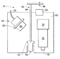
図1は、複数の印刷版12、例えばフレキソ印刷版をキャリアシート14上に取り付けるための装置を描いており、各印刷版12は第1および第2のトンボ、つまり見当マークを有する。印刷版取り付け装置10は、上面にキャリアシート14が取り付けられる可動テーブル16と、この可動テーブル16に隣接して案内支持部材22に移動可能に取り付けられる第1カメラアセンブリィ18と、可動テーブル16に隣接して案内支持部材22に移動可能に取り付けられる第2カメラアセンブリィ20とを具えている。第1カメラアセンブリィ18は、第1の見当マークを観察するための第1表示ユニット26の第1TVモニタ24に接続し、第2カメラアセンブリィ20は、第2の見当マークを観察するための第2表示ユニット30の第2TVモニタ28に接続している。この好ましい実施例において、第1および第2のTVモニタ24, 28は、作動コントローラ32を介してそれぞれ第1および第2のカメラアセンブリィ18, 20に接続している。さらに、この印刷版取り付け装置10は、第1および第2のカメラアセンブリィ18, 20に接続して可動テーブル16に対して各カメラアセンブリィ18, 20を独立に移動するための手段を有する。また、作動コントローラ32は移動手段に接続してそこに移動信号を送出する。作動コントローラ32は、各印刷版12に対する2つの見当マークに対応した少なくとも2つの移動信号をライン34, 36を介して発する。作動コントローラ32で発せられた移動信号は、作動コントローラ32の前もってプログラムしたメモリカードからか、あるいはこれに接続するコンピュータ38によって実行されるソフトウェアプログラムから制御される。
【0026】
可動テーブル16は、一対の溝付きレール(図示せず)上にボールレースを有する案内ブロックを用いて固定ベース(図示せず)の上に摺動可能に取り付けられており、溝付きレールは、案内支持部材22に対して直交する、以下でy方向と呼称される方向への可動テーブル16の移動をもたらすように、固定ベースの上面に配置されている。案内支持部材22は、エンドサポート40によって固定ベースに対してその端部が可動テーブル16の上に水平かつこれと平行に固定されている。案内支持部材22は、第1カメラアセンブリィ18に取り付けたねじ案内ブラケットに支持される第1ねじ軸42を有し、この第1ねじ軸42が回された場合、第1カメラアセンブリィ18が案内支持部材22と平行に可動テーブル16の上を移動するようになっている。この案内支持部材22に対する平行移動の方向は、以下においてx方向と呼称される。第2ねじ軸44は、第2カメラアセンブリィ20に同様に連結されている。第1および第2のねじ軸42, 44は、共にエンドサポート40内に設置したDCサーボモータ(図示せず)によって回され、これらDCサーボモータは作動コントローラ32に接続し、この作動コントローラ32からライン34, 36を介して送信される移動信号により制御される。第3ねじ軸(図示せず)は、y方向の可動テーブル16の移動をもたらし、この移動は、第1および第2のカメラアセンブリィ18, 20のx方向の独立した移動を行う。第3ねじ軸も、DCサーボモータによって回され、作動コントローラ32に接続してこの作動コントローラ32からライン46を介して送信される移動信号によって制御される。希望するのであれば、以下に説明するような前もってプログラムした座標の代わりに、ジョイスティック48を用いることによって移動信号を手動で発生させることができる。また、可動テーブル16にはx方向に延在する位置決めバー50がそのx方向前端に沿って正確に位置決め状態で設けられている。
【0027】
図2は、y方向に移動可能な可動テーブル16の上に取り付けられ、x方向に移動可能に予め描かれた第2カメラアセンブリィ20を描いている。第2カメラアセンブリィ20は、カメラ52と、カメラレンズ54と窓(window)56とオフセット調整アセンブリィ58とを有する。また、第2カメラアセンブリィ20は、予備見当合わせ光アセンブリィ(図示せず)を有し、これは第1カメラアセンブリィ18に関して以下により詳細に記述される予備見当合わせ光アセンブリィ80と同じものである。カメラ52およびレンズ54は、オフセット調整アセンブリィ58上のカメラ取り付けブラケット62に固定具64を用いて取り付けられており、カメラ52およびレンズ54が可動テーブル16の方に向けられている。窓56は、レンズ54が塵埃で汚されないようにレンズ54に取り付けられている。第1および第2のカメラアセンブリィ18, 20と可動テーブル16とが特定の見当マークに対してx, y座標に対応した位置にある時、カメラ52のレンズ54は、キャリアシート14(または特定の印刷版12の見当マーク)上にピントが合う。
【0028】
オフセット調整アセンブリィ58は、そこに取り付けられるカメラ52およびレンズ54を有するカメラ取り付けブラケット62のための可動ステージ66を有する。可動ステージ66は、案内支持部材22の第1ねじ軸42が取り付けられるねじ案内ブラケットを有するリニアアクチュエータ68に取り付けられ、案内支持部材22の第1ねじ軸42は、x方向のリニア軸受70に沿ってねじ案内ブラケットを動かすための手段として共に機能する。可動ステージ66は、ロータリエンコーダおよびモータ(図示せず)を有し、y方向のカメラ52の移動を可能とする。
【0029】
オフセット調整アセンブリィ58は、1つあるいはそれ以上の印刷版12がキャリアシート14に対して交換されるか、あるいは1つあるいはそれ以上の追加の印刷版12が最初の取り付け作業に次いでキャリアシート14に取り付けられる場合、特に有効である。使用者側において、しばしば用いられる「使い古し」のキャリアシートから印刷版を交換することは、極めて困難である。これら「使い古し」のキャリアシートの大部分は、電子システムを用いずに取り付けられており、従ってこれらの古い版台の全部が正しく平行ではない。1台のカメラのオフセット機能は、古い印刷版と同じ位置に新しい印刷版の正確な取り付けを可能とするけれども、このような印刷版は、100%平行ではない。本発明によるオフセット調整アセンブリィ58は、交換されるか、あるいは新たな印刷版を第2のカメラアセンブリィ20のカメラ52のy方向の座標に調整して正確に見当合わせすることをオペレータに可能とする。オフセット調整アセンブリィ58は、他のキャリアシート上の対応する印刷版を次に取り付けるための調整オフセットを記憶し、従ってそれぞれ連続する印刷版の取り付けのためにリセットしたり再設定したりする必要がない。
【0030】
第1カメラアセンブリィ18は、オフセット調整アセンブリィ58を除いて上述した第2カメラアセンブリィ20と同じであり、カメラ取り付けブラケット60が第2ねじ軸44に連結されたねじ案内ブラケットに直接取り付けられている。また、図2に示すように、各カメラアセンブリィ18, 20は、リニアエンコーダ72、例えば Anilam 直線スケールを有し、x軸線に沿った各カメラアセンブリィ18, 20の正確な位置を測定するために作動コントローラ32に接続している。可動テーブル16は、ロータリエンコーダ(図示せず)を有し、y軸線に沿った可動テーブル16の正確な位置を測定するために作動コントローラ32に接続している。x, y両方の軸線に沿った各カメラアセンブリィ18, 20の位置は、作動コントローラ32から伝えられ、第1および第2の表示ユニット26, 30にそれぞれ表示され、可動テーブル16に対して各カメラアセンブリィ18, 20のx, y位置座標に対する数値が表示される。作動コントローラ32は、可動テーブル16および各カメラアセンブリィ18, 20の座標位置を記憶し、取り付け作業中に可動テーブル16が動いた場合、可動テーブル16は望ましいy座標位置に自動的に戻されよう。
【0031】
図3は、第1カメラアセンブリィ18を描いており、上述のようにy方向に移動可能な可動テーブル16の上方に取り付けられ、x方向に移動可能である。第1カメラアセンブリィ18は、カメラ74と、カメラレンズ76と、窓78と、予備見当合わせ光アセンブリィ80と、描画ペンアセンブリィ82とを有する。カメラ74およびレンズ76および窓78は、カメラ74およびレンズ76がオフセット調整アセンブリィ58に取り付けられるのではなく、第2ねじ軸44が連結されるねじ案内ブラケットに直接取り付けられたカメラ取り付けブラケット60に装着される点を除き、上述した第2カメラアセンブリィ20と同じである。予備見当合わせ光アセンブリィ80は、可撓性の光ファイバケーブル86に組み合わされる集光レンズ84を有する。光ファイバケーブル86は、案内支持部材22に配置されるクォーツハロゲン照明器具の如き光源(図示せず)に連結されている。集光レンズ84は、固定具88によりカメラ取り付けブラケット60に対して適正な場所に保持され、レンズ76およびカメラ74の直下のキャリアシート14上の領域に光を照らすように配置される。予備見当合わせ光アセンブリィ80は、このキャリアシート14上の領域の他に、所定の見当マークに対応するx, y座標位置の印刷版12上の見当マークも照明する。
【0032】
なお、第1カメラアセンブリィ18は、図示しないけれども上述したような予備見当合わせ光アセンブリィ80を有する。
【0033】
第1カメラアセンブリィ18は、描画ペンアセンブリィ82の描画ペン92を配置するための開口90を有する。描画ペンアセンブリィ82は、プル形の中空ソレノイド98に吸引される電磁プランジャ96を有する可動ロッド94に取り付けられた描画ペン92を具えている。描画ペン92は、自動プロッタで描画するために用いられる一般的なペンであり、例えば Hewlett Packardから得ることができる。使用状態にない場合、描画ペン92は図示の如き格納位置に退避している。キャリアシート14上の容器レイアウトの打ち抜き線 (die cut lines)あるいは折り返し線 (folding lines)を描くために描画ペンアセンブリィ82が使用され、描画ペン92は、電磁プランジャ96が中空ソレノイド98に入り込む待機位置に手動で押し下げられる。中空ソレノイド98が動作して描画ペン92がキャリアシート14と接触するように動かされる。第1カメラアンセブリィ18および可動テーブル16は、オペレータがこの取り付け装置10のコンピュータ38の適当なファイルを選択することにより動かされ、キャリアシート14上に線を描く。
【0034】
各カメラアセンブリィ18, 20は、カメラ52, 74に接続する第1および第2の表示ユニット26, 30を有する独立したビデオ画像システムの一部をそれぞれ形成する。各表示ユニット26, 30は、第1および第2のTVモニタ24, 28をそれぞれ有し、垂直および水平線を具えた十字線画像をTVモニタスクリーンに生ずる電子交差線(electronic cross-line )発生器(図示せず)に接続している。垂直および水平線の交点は、印刷版12の一部、すなわちカメラレンズ54, 76の中心直下に配置した見当マークと正確に一致する。各TVカメラ52, 74は、一般的には印刷版12の目標領域を25倍に拡大する。また、各表示ユニット26, 30は、数値すなわちデジタル表示器100, 102を具えており、見当マークのx, y位置座標が読み出される。十字線を発生するために用いられる技術および受信画像を表示する技術およびカメラの座標位置を読み出す技術は、この分野において周知である。
【0035】
本発明における十字線発生器は、アルファベット/数字記号、例えばA1, A2, …,B1, B2,…の形態で各TVモニタ24, 28に情報を表示するための符号発生器を有し、これらはキャリアシート14に取り付けられる各印刷版12に対する第1および第2の見当マークに対応する。符号発生器は、作動コントローラ32およびコンピュータ38から次に取り付けられるべき印刷版12に関する情報を受信する。作動コントローラ32によって相互に接続されるカメラアセンブリィ18, 20と個々の表示ユニット26, 30とは、可動テーブル16上に保持されたキャリアシート14の印刷版12の正確な位置決めを可能とする光学システムをもたらしている。
【0036】
段ボール容器、例えば段ボール箱に対する上述した印刷版取り付け装置10の一般的な作業工程を以下に記載する。この工程の第1のステップは、印刷されるべき色に対する貼込み台紙の準備である。貼込み台紙は、見当マークのすべてを含む印刷されるべき図柄を実物大に描いたものであり、展開した平らな容器、すなわち印刷されるべき基体のレイアウトに重ねられる。見当マークを含む図柄および容器レイアウトが描かれ、および/または処理され、そしてプリプレスコンピュータの一般的なファイルに電子的に格納される。キャリアシート14に取り付けられるべき各印刷版12のため、図柄製作者は、キャリアシート14上の予め設定した原点およびキャリアシート14に対する印刷版12のための第1の見当マークと第2の見当マークとの位置に対する印刷版の位置を決定する。各印刷版12に対する位置および見当マークは、電子的に格納される。さらに、容器のレイアウトに関する打ち抜き線および折り返し線は、電子的に格納される。見当マークを含む電子的に格納した図柄が印刷版12のレリーフパターンを形成するのに用いられるマスクを生成するために使用されることは、当業者に理解されよう。
【0037】
キャリアシート14は可動テーブル16上に置かれる。キャリアシート14は、概ね厚肉の可撓性プラスチック材料である。一般的なキャリアシート14は、ポリエステルで作られ、0. 10mmから5. 0mmまでの範囲の厚みを有する。キャリアシート14は、位置決めバー50を用いて可動テーブル16上に配置される。位置決めバー50は、MATTHEWS(登録商標)ロックあるいは同様な位置決め器具であってよい。多くの場合において、版胴に設けた特殊固定器具は、印刷中にキャリアシート14を所定箇所に保持するのに用いられる。これらが使用される場合、位置決めバー50に対して使用されるのと同じ同一型式の固定器具を有することが都合がよい。また、キャリアシート14は、見当合わせ穴と取り付けピンとを用いて位置決め可能である。取り付けピンまたは位置決めバー50は、可動テーブル16に対して一体的あるいは取り外し可能に装着可能である。キャリアシート15は、例えば平たい重りや真空吸引を使用することによって、その移動が阻止される。真空吸引を使用する可動テーブル16は、寸法の異なるキャリアシートに対応させるために複数の吸引領域を有することが好ましい。
【0038】
キャリアシート14にそれぞれ取り付けられるべき印刷版12のため、貼込み作業者は、記録した印刷版位置および見当マークをプリプレスコンピュータから引き出し、取り付け装置10のコンピュータ38のファイルに取り込む。各カメラアセンブリィ18, 20は、予め設定した原点位置に可動テーブル16上を独立に動かされる。これは、キャリアシート14の最前部の一方の隅や、キャリアシート14の最前部の中点などであってよい。可動テーブル16に対する各カメラアセンブリィ18, 20の移動は、溝付きレールに沿ったy方向の可動テーブル16の移動と、案内支持部材22に沿ったx方向の各カメラアセンブリィ18, 20の移動とによって達成される。各デジタル表示器100, 102は、望ましい原点においてx=0, y=0に調整される。可動テーブル16は、y方向に動かされると共に各カメラアセンブリィ18, 20は、各カメラアセンブリィ18, 20が個々の見当マークに対して記録したx, y座標となるまで、案内支持部材22に沿ってx方向に動かされる。第1カメラアセンブリィ18は、作動コントローラ32からの第1の移動信号に応じ、第1の印刷版12の第1の見当マークに対して記録されたx, y座標を有する位置まで、案内支持部材22に沿って動かされる。また、第2のカメラアセンブリィ20は、作動コントローラ32からの第2の信号に応じ、第2の見当マークに対して記録されたx, y座標を有する位置まで案内支持部材22に沿って動かされる。各カメラアセンブリィ18, 20は、固定手段(図示せず)を用いて所定箇所に固定される。各カメラアセンブリィ18, 20の予備見当合わせ光アセンブリィ80は、第1の印刷版12のための個々の見当マークが形成されたキャリアシート14の部分を照明する。
【0039】
粘着テープは、印刷版12の非レリーフ(非印刷)側に設けられる。この粘着テープは、取り付け作業中、剥離を容易にする保護シート、例えばワックス紙でカバーされていることが好ましく、印刷版12に対する粘着テープの中央部分は、粘着性を持たせるためにカバーされていない。第1の印刷版12は、非レリーフ側がキャリアシート14を向くと共に第1および第2の見当マークを含むレリーフ側がキャリアシート14上の予備見当合わせ光アセンブリィ80の下方位置に動かされる。そして、印刷版12がキャリアシート14上に載置され、印刷版12の第1の見当マークが第1カメラアセンブリィ18の予備見当合わせ光アセンブリィ80によって照明され、第1TVモニタ24のスクリーンに表示された十字線マークと合致させ、印刷版12の第2の見当マークが第2カメラアセンブリィ20の予備見当合わせ光アセンブリィ80によって照明され、第2TVモニタ28のスクリーンに表示された十字線マークと合致させられる。第1の印刷版12は、キャリアシート14上の所定箇所に押し付けられ、露出している粘着領域に沿ってキャリアシート14に付着する。第1の印刷版12の粘着領域の両側の保護シートは、この印刷版12から慎重に取り外され、印刷版12の残った領域がキャリアシート14に対して接着するように、その所定箇所がキャリアシート14に押し付けられる。
【0040】
次に、第2の印刷版のための見当合わせ座標が引き出され、各カメラアセンブリィ18, 20ならびに可動テーブル16は、所定箇所に動かされ、第2の印刷版が上述したように準備される。これは、キャリアシート14に取り付けられるべきすべての残りの印刷版に対して繰り返される。印刷版取り付け作業中に可動テーブル16が望ましい見当合わせ座標から離れるように動かすことは可能である。この場合、取り付けられている印刷版12のためのy座標を記憶している作動コントローラ32は、正しいy座標位置に可動テーブル16を戻すように作動可能である。
【0041】
本発明は、2つのカメラアセンブリィ18, 20を必要とするだけで、多数の印刷版をキャリアシート14に取り付け可能であるという点で利点を生ずる。キャリアシート14を可動テーブル16上の所定箇所に位置させた後、好ましくは印刷版12がキャリアシート14に取り付けられる前に、展開した平らな容器のレイアウトがキャリアシート14上に描かれ、例えば、容器のゆがんだ打ち抜き線およびゆがんだ折り返し線が表示される。第1カメラアセンブリィ18は原点位置に配置される。描画ペンアセンブリィ82の描画ペン92は、描画ペン92がキャリアシート14と接触するように動かされる。そして、可動テーブル16および/または第1カメラアセンブリィ18が動かされ、描画ペン92は打ち抜き線と、折り返し線と、容器のその他の関連するマークとをキャリアシート14上に描く。キャリアシート14を作ることは、印刷機による印刷前に、印刷版12が印刷されるべき望ましい箱に対してキャリアシート14上に正確に配置され、印刷される箱が視覚化されるように援助することを保証する。
【0042】
全ての印刷版12がキャリアシート14に取り付けられた後、各印刷版12の周縁は、取り扱いおよび/または印刷中にキャリアシート14から印刷版12が剥がれないようにエッジシーラントで適切にシールされる。そして、印刷版12と共にキャリアシート14が版胴に取り付けられる。位置決めバー50は、版胴に対してキャリアシート14を取り付けるために使用可能である。通常、キャリアシート14は、テンションバンドか、あるいは版胴に設けた特殊固定装置によって版胴に保持される。
【0043】
【発明の効果】
本発明によると、印刷版に形成された第1の見当マークを観察するための第1ビデオモニタに接続する第1カメラアセンブリィと、印刷版に形成された第2の見当マークを観察するための第2ビデオモニタに接続する第2カメラアセンブリィとをテーブルに対して独立に移動するようにし、テーブルに隣接する支持部材に移動可能に取り付けられた第1のカメラアセンブリィが接続する第1のビデオモニタの十字線画像と第1の見当マークとを合致させると共に支持部材に移動可能に取り付けられた第2カメラアセンブリィが接続する第2ビデオモニタの十字線画像と第2の見当マークとを合致させるようにしたので、穿設作業や取り付けピンを使用することなく、キャリアシート上に1つ以上の印刷版を取り付けることができる。
【0044】
また、手動計算および手動配置の必要性を除去して代わりにキャリアシート上の印刷版の正確な位置を自動的に決定することができる。
【0045】
さらに、多色カラー印刷のために他のキャリアシートに取り付けた印刷版に対し、最初およびこれに続く見当合わせを確実に行うことができる。
【図面の簡単な説明】
【図1】本発明をフレキソ印刷版に応用した一実施例の全体を表す概略斜視図である。
【図2】図1に示した実施例における第2カメラアセンブリィの概略側面図であり、カメラとオフセット調整アセンブリィとを示す。
【図3】図1に示した実施例における第1カメラアセンブリィの概略正面図であり、カメラと予備見当合わせ光アセンブリィと描画ペンアセンブリィとを示す。
【符号の説明】
10 装置
12 印刷版
14 キャリアシート
16 可動テーブル
18 第1カメラアセンブリィ
20 第2カメラアセンブリィ
22 案内支持部材
24 第1TVモニタ
26 第1表示ユニット
28 第2TVモニタ
30 第2表示ユニット
32 作動コントローラ
34, 36 ライン
38 コンピュータ
40 エンドサポート
42 第1ねじ軸
44 第2ねじ軸
46 ライン
48 ジョイスティック
50 位置決めバー
52 カメラ
54 カメラレンズ
56 窓
58 オフセット調整アセンブリィ
60, 62 カメラ取り付けブラケット
64 固定具
66 可動ステージ
68 リニアアクチュエータ
70 リニア軸受
72 リニアエンコーダ
74 カメラ
76 カメラレンズ
78 窓
80 予備見当合わせ光アセンブリィ
82 描画ペンアセンブリィ
84 集光レンズ
86 光ファイバケーブル
88 固定具
90 開口
92 描画ペン
94 可動ロッド
96 電磁プランジャ
98 プル形ソレノイド
100, 102 デジタル表示器[0001]
BACKGROUND OF THE INVENTION
The present invention relates to a method and apparatus for mounting a printing plate on a carrier sheet, and more particularly to a method and apparatus for registering and mounting a flexographic printing plate on a carrier sheet.
[0002]
[Prior art]
Flexographic printing plates are elastic relief image plates made of rubber, photosensitive polymers or similar materials and are used to print on a wide variety of articles. One important step in the printing process is the precise positioning of the printing plate relative to the plate cylinder. It is necessary to position the printing plate so that the printing is parallel to the axis of the plate cylinder, ie not twisted. Also, in multicolor printing, printing plates corresponding to different colors need to be aligned so that they are printed in register.
[0003]
This positioning is often accomplished using a pin registration drill and sticker. In this case, the plate cylinder is typically removed from the printing press and the printing plate is attached to the plate cylinder using registration holes often associated with separate applicators.
[0004]
However, in many common printing presses used to print cardboard containers, the plate cylinder is usually not removed from the printing press. Conventional methods of attaching flexographic printing plates for cardboard printing require the use of a carrier sheet and a paste / proof machine unit. One or more printing plates are secured via adhesive or adhesive tape on a large flexible sheet known as a carrier sheet. For example, in cardboard printing of cardboard boxes, a relatively small area on both sides of the box is often printed, which requires mounting multiple printing plates on the carrier sheet. The printing plate is placed on the carrier sheet by manually measuring the position of the printing plate using a light guide and a reflector. Then, the carrier sheet is disposed on the plate cylinder of the printing press. For printing in the corrugated post printing market, it is necessary to deploy one-color or multi-color products. For multicolor printing, the printing plates for each successive color are placed on their carrier sheet using a paste / proofer unit with a reflector.
[0005]
A major advance in the method of mounting printing plates for corrugated board printing has been achieved by the introduction of single-head drills. The printing press can use this single head drill to make registration holes in both the carrier sheet and the printing plate. And a printing plate is fixed to a carrier sheet using an attachment pin and an adhesive tape. If the printing plate is fixed, the pins are removed. Therefore, the line alignment of the printing plate on the carrier sheet is the same for each color, and the need to use a pasting / calibrating machine unit can be eliminated. Also, both the speed and accuracy of the attachment process can be improved.
[0006]
[Problems to be solved by the invention]
The method of attaching one or more printing plates on a carrier sheet using a pasting / calibrator unit is time consuming, highly dependent on the skill of the operator, and can lead to inconsistent results. is there. In the current situation where there is an increasing demand for improvement in registration work, this method is not satisfactory.
[0007]
The method of mounting one or more printing plates on a carrier sheet using a single head drill requires time for drilling registration holes in the carrier sheet and the printing plate independently, and the wrong printing plate can be Such placement and other errors cannot be ruled out because of the possibility of mounting in the wrong place on the seat.
[0008]
Further, a corrugated board printing machine after a printing operation often holds a carrier sheet on which a printing plate of each color is attached for the next printing operation. However, problems arise when there is a possibility of removing one or more printing plates from a stored carrier sheet. This is because it is extremely difficult to exchange a printing plate in register with another. Also, additional colors may need to be added during subsequent printing, and new colors are conventionally used to ensure registration with other printing plates that are correctly mounted on the carrier sheet. It is very difficult to attach the printing plate to the exact position of the carrier sheet.
[0009]
OBJECT OF THE INVENTION
It is an object of the present invention to provide a method and apparatus for attaching one or more printing plates to a carrier sheet without using drilling operations or attachment pins.
[0010]
Another object of the present invention is to provide a method and apparatus that can automatically determine the exact position of a printing plate on a carrier sheet, eliminating the need for manual calculations and manual placement.
[0011]
Another object of the present invention is the attachment of a printing plate that can ensure initial registration and subsequent registration to printing plates mounted on other carrier sheets for multicolor printing. It is to provide a method and apparatus.
[0012]
[Means for Solving the Problems]
A first aspect of the present invention is a printing plate mounting apparatus for mounting a plurality of printing plates each having first and second registration marks to a carrier sheet, a table mounted on a fixed base, and the table Adjacent to the support member Against A first camera assembly movably mounted and connected to a first video monitor for observing the first registration mark; and on the support member adjacent to the table Against A second camera assembly movably mounted and connected to a second video monitor for observing the second registration mark; and coupled to the first and second camera assemblies; A moving means for independently moving the first and second camera assemblies, and a movement signal connected to the moving means for transmitting, and at least two corresponding to the first and second registration marks of each printing plate And an operation controller having signal generating means for generating two movement signals. The first and second camera assemblies are movable in a first direction along the support member, and the second camera assembly is along a second direction orthogonal to the first direction. Has an offset adjustment assembly with a moving movable stage It is characterized by this.
[0013]
The second aspect of the present invention is a printing plate mounting method for mounting a plurality of printing plates each having first and second registration marks to a carrier sheet,
(a) placing the carrier sheet on a table attached to a fixed base;
(b) moving means for moving the table and moving means for moving the first camera assembly to a first position coordinate corresponding to the first register mark for mounting the first printing plate; Sending a movement signal of 1 from the actuation controller;
(c) A second movement signal is sent to the operation controller for moving means for moving the second camera assembly to a second position coordinate corresponding to the second registration mark for mounting the first printing plate. Sending from
(d) moving the table and the first and second camera assemblies according to the first and second movement signals, and moving the first and second camera assemblies to the first and second Positioning to the position coordinates of The first and second camera assemblies are movable in a first direction along a support member to which the first and second camera assemblies are attached, and the second camera assembly is a second one orthogonal to the first direction. Step having an offset adjustment assembly with a movable stage moving along two directions When,
(e) The first printing plate is placed on the carrier sheet below the first and second camera assemblies, and the first printing plate is movably attached to a support member adjacent to the table. The first registration mark is matched with the cross-hair image of the first video monitor to which the camera assembly is connected, and the second camera assembly is movably attached to the support member adjacent to the table. Matching the second registration mark to the crosshair image of the second video monitor;
(f) A step of fixing the first printing plate on the carrier sheet after the positioning step is provided.
[0014]
DETAILED DESCRIPTION OF THE INVENTION
In the printing plate mounting apparatus according to the first aspect of the present invention, the first and second camera assemblies are movable in the first direction along the support member, and the second camera assembly is moved in the first direction. It may have an offset adjustment assembly having a movable stage that moves along a second direction orthogonal to each other. In this case, the table preferably has means connected to the table to move the table along the second direction with respect to the fixed base.
[0015]
The first and second camera assemblies may each include a camera and a pre-register light assembly, and the first camera assembly may have a drawing pen assembly for marking on the carrier sheet. . In this case, the drawing pen assembly preferably comprises a drawing pen attached to a movable rod actuated by an electromagnetic plunger.
[0016]
The moving means may comprise a linear actuator that receives the movement signal and an encoder that measures the moving distance of the first and second camera assemblies or tables along the first and second directions.
[0017]
It is also possible to further comprise first and second digital indicators connected to the actuation controller for displaying corresponding positions of the first and second camera assemblies along the first and second directions, respectively. .
[0018]
The signal generating means may comprise a software program executed on a computer connected to the actuation controller or may comprise a preprogrammed memory card that is incorporated into the actuation controller.
[0019]
In the printing plate attachment method according to the second aspect of the present invention, the steps (b) to (f) may be repeated for the next printing plate attached to the carrier sheet.
[0020]
The step of transmitting the first and second movement signals from the operation controller may be performed by issuing the first and second movement signals from a software program executed on a computer connected to the operation controller. Alternatively, it may be performed by issuing first and second movement signals from a pre-programmed memory card incorporated in the operation controller.
[0022]
The first camera assembly may include a drawing pen assembly having a drawing pen, and may further include a step of drawing on the carrier sheet with the drawing pen.
[0023]
Each moving means may comprise a linear actuator that receives a movement signal.
[0024]
【Example】
An embodiment in which a printing plate mounting apparatus capable of realizing the printing plate mounting method according to the present invention is applied to a flexographic printing plate will be described in detail with reference to FIGS. 1 to 3. The present invention is not limited to this embodiment, and can be applied to technologies in other fields including similar problems.
[0025]
FIG. 1 depicts an apparatus for mounting a plurality of
[0026]
The movable table 16 is slidably mounted on a fixed base (not shown) using a guide block having a ball race on a pair of grooved rails (not shown). It is arranged on the upper surface of the fixed base so as to effect the movement of the movable table 16 in a direction perpendicular to the
[0027]
FIG. 2 depicts a
[0028]
The offset
[0029]
The offset
[0030]
The
[0031]
FIG. 3 depicts the
[0032]
The
[0033]
The
[0034]
Each
[0035]
The crosshair generator in the present invention has a code generator for displaying information on each
[0036]
A general working process of the printing
[0037]
The carrier sheet 14 is placed on the movable table 16. The carrier sheet 14 is a generally thick flexible plastic material. A typical carrier sheet 14 is made of polyester and has a thickness ranging from 0.10 mm to 5.0 mm. The carrier sheet 14 is disposed on the movable table 16 using the
[0038]
For each
[0039]
The adhesive tape is provided on the non-relief (non-printing) side of the
[0040]
Next, the registration coordinates for the second printing plate are retrieved, and each
[0041]
The present invention provides an advantage in that a large number of printing plates can be attached to the carrier sheet 14 by requiring only two
[0042]
After all the
[0043]
【The invention's effect】
According to the present invention, a first camera assembly connected to a first video monitor for observing a first registration mark formed on the printing plate, and a second registration mark formed on the printing plate. The second camera assembly connected to the second video monitor is moved independently with respect to the table, and the first camera assembly movably attached to the support member adjacent to the table is connected to the first camera assembly. The crosshair image of the second video monitor and the second registration mark connected to the second camera assembly movably attached to the support member while matching the crosshair image of the video monitor with the first registration mark Therefore, one or more printing plates can be mounted on the carrier sheet without using a drilling operation or mounting pins.
[0044]
Also, the need for manual calculation and manual placement can be eliminated and instead the exact position of the printing plate on the carrier sheet can be automatically determined.
[0045]
Furthermore, the first and subsequent registrations can be reliably performed on printing plates attached to other carrier sheets for multicolor printing.
[Brief description of the drawings]
FIG. 1 is a schematic perspective view showing the whole of an embodiment in which the present invention is applied to a flexographic printing plate.
FIG. 2 is a schematic side view of a second camera assembly in the embodiment shown in FIG. 1, showing the camera and offset adjustment assembly.
3 is a schematic front view of a first camera assembly in the embodiment shown in FIG. 1, showing a camera, a pre-registration light assembly, and a drawing pen assembly.
[Explanation of symbols]
10 devices
12 printing plate
14 Carrier sheet
16 Movable table
18 First camera assembly
20 Second camera assembly
22 Guide support member
24 First TV monitor
26 First display unit
28 Second TV monitor
30 Second display unit
32 Actuation controller
34, 36 lines
38 computers
40 End support
42 First screw shaft
44 Second screw shaft
46 lines
48 Joystick
50 Positioning bar
52 Camera
54 Camera lens
56 windows
58 Offset adjustment assembly
60, 62 Camera mounting bracket
64 Fixture
66 Movable stage
68 Linear actuator
70 Linear bearing
72 Linear encoder
74 cameras
76 Camera lens
78 windows
80 Pre-registration light assembly
82 Drawing Pen Assembly
84 condenser lens
86 Optical fiber cable
88 Fixture
90 opening
92 Drawing pen
94 Movable rod
96 Electromagnetic plunger
98 Pull type solenoid
100, 102 Digital display
Claims (2)
固定ベース上に取り付けられるテーブルと、
このテーブルに隣接して支持部材に対し移動可能に取り付けられ、前記第1の見当マークを観察するための第1ビデオモニタに接続する第1カメラアセンブリィと、
前記テーブルに隣接して前記支持部材に対し移動可能に取り付けられ、前記第2の見当マークを観察するための第2ビデオモニタに接続する第2カメラアセンブリィと、
前記第1および第2のカメラアセンブリィに連結され、前記テーブルに対してこれら第1および第2のカメラアセンブリィを独立に移動させる移動手段と、
この移動手段に接続して移動信号を送信し、各印刷版の前記第1および第2の見当マークに対応した少なくとも2つの移動信号を発生させる信号発生手段を有する作動コントローラと
を具え、前記第1および第2のカメラアセブリィは、前記支持部材に沿って第1の方向に移動自在であり、前記第2カメラアセンブリィは、前記第1の方向と直交する第2の方向に沿って移動する可動ステージを持ったオフセット調整アセンブリィを有することを特徴とする印刷版取り付け装置。A printing plate mounting apparatus for mounting a plurality of printing plates each having first and second registration marks to a carrier sheet,
A table mounted on a fixed base;
Movably mounted against the support member adjacent to the table, a first camera assembly I connected to the first video monitor for viewing said first registration marks,
Movably mounted against the said support member adjacent said table, and a second camera assembly I connected to the second video monitor for viewing said second registration mark,
Moving means coupled to the first and second camera assemblies and independently moving the first and second camera assemblies relative to the table;
This was connected to a moving means to transmit a movement signal, comprising an actuating controller having at least two signal generating means for generating a movement signal corresponding to the first and second register marks of the respective printing plate, the first The first and second camera assemblies are movable in a first direction along the support member, and the second camera assembly is movable in a second direction orthogonal to the first direction. A printing plate mounting apparatus comprising an offset adjustment assembly having a stage .
(a) 固定ベースに取り付けられるテーブル上に前記キャリアシートを載置するステップと、
(b) 前記テーブルを移動する移動手段と、第1の前記印刷版を取り付けるための前記第1の見当マークに対応した第1の位置座標へ第1カメラアセンブリィを移動する移動手段とに第1の移動信号を作動コントローラから送信するステップと、
(c) 前記第1の印刷版を取り付けるための前記第2の見当マークに対応した第2の位置座標へ第2カメラアセンブリィを移動する移動手段に対し、第2の移動信号を前記作動コントローラから送信するステップと、
(d) 前記テーブルと前記第1および第2のカメラアセンブリィとを前記第1および第2の移動信号に応じて移動させ、前記第1および第2のカメラアセンブリィを前記第1および第2の位置座標にそれぞれ位置決めするステップであって、前記第1および第2のカメラアセブリィは、これらが取り付けられる支持部材に沿って第1の方向に移動自在であり、前記第2カメラアセンブリィは、前記第1の方向と直交する第2の方向に沿って移動する可動ステージを持ったオフセット調整アセンブリィを有するステップと、
(e) 前記第1および第2のカメラアセンブリィの下方の前記キャリアシート上に前記第1の印刷版を載置し、前記テーブルに隣接する支持部材に移動可能に取り付けられた前記第1のカメラアセンブリィが接続する第1のビデオモニタの十字線画像に前記第1の見当マークを合致させると共に前記テーブルに隣接する前記支持部材に移動可能に取り付けられた前記第2カメラアセンブリィが接続する前記第2ビデオモニタの十字線画像に前記第2の見当マークを合致させるステップと、
(f) この位置決めステップの後に前記キャリアシート上に前記第1の印刷版を固定するステップと
を具えたことを特徴とする印刷版取り付け方法。A printing plate mounting method for mounting a plurality of printing plates each having first and second registration marks to a carrier sheet,
(a) placing the carrier sheet on a table attached to a fixed base;
(b) moving means for moving the table and moving means for moving the first camera assembly to a first position coordinate corresponding to the first register mark for mounting the first printing plate; Sending a movement signal of 1 from the actuation controller;
(c) A second movement signal is sent to the operation controller for moving means for moving the second camera assembly to a second position coordinate corresponding to the second registration mark for mounting the first printing plate. Sending from
(d) moving the table and the first and second camera assemblies according to the first and second movement signals, and moving the first and second camera assemblies to the first and second Each of the first and second camera assemblies is movable in a first direction along a support member to which the first and second camera assemblies are attached, and the second camera assembly includes Having an offset adjustment assembly having a movable stage moving along a second direction orthogonal to the first direction ;
(e) The first printing plate is placed on the carrier sheet below the first and second camera assemblies, and the first printing plate is movably attached to a support member adjacent to the table. The first registration mark is matched with the cross-hair image of the first video monitor to which the camera assembly is connected, and the second camera assembly is movably attached to the support member adjacent to the table. Matching the second registration mark to the crosshair image of the second video monitor;
(f) A method of attaching a printing plate, comprising the step of fixing the first printing plate on the carrier sheet after the positioning step.
Applications Claiming Priority (2)
| Application Number | Priority Date | Filing Date | Title |
|---|---|---|---|
| US08/898,098 | 1997-07-22 | ||
| US08/898,098 US5850789A (en) | 1997-07-22 | 1997-07-22 | Method and apparatus for mounting printing plates |
Publications (2)
| Publication Number | Publication Date |
|---|---|
| JPH1177983A JPH1177983A (en) | 1999-03-23 |
| JP4319267B2 true JP4319267B2 (en) | 2009-08-26 |
Family
ID=25408943
Family Applications (1)
| Application Number | Title | Priority Date | Filing Date |
|---|---|---|---|
| JP20679798A Expired - Fee Related JP4319267B2 (en) | 1997-07-22 | 1998-07-22 | Printing plate mounting method and apparatus |
Country Status (4)
| Country | Link |
|---|---|
| US (1) | US5850789A (en) |
| EP (1) | EP0893254B1 (en) |
| JP (1) | JP4319267B2 (en) |
| DE (1) | DE69803013T2 (en) |
Cited By (2)
| Publication number | Priority date | Publication date | Assignee | Title |
|---|---|---|---|---|
| US8827738B2 (en) | 2009-11-03 | 2014-09-09 | Orica Explosives Technology Pty Ltd | Connector, and methods of use |
| DE102018212473A1 (en) | 2017-08-25 | 2019-02-28 | Yazaki Corporation | Ladder connection arrangement of plate-shaped guide elements |
Families Citing this family (38)
| Publication number | Priority date | Publication date | Assignee | Title |
|---|---|---|---|---|
| NL1007631C2 (en) * | 1997-11-27 | 1999-06-14 | Av Flexologic Bv | Method and device for positioning printing plates. |
| JP3190956B2 (en) * | 1998-11-02 | 2001-07-23 | 株式会社金田機械製作所 | Manufacturing method of printing plate for newspaper printing |
| US6282027B1 (en) * | 1999-03-26 | 2001-08-28 | Vari-Lite, Inc. | Zoomable beamspreader with matched optical surfaces for non-imaging illumination applications |
| JP3357024B2 (en) * | 1999-04-19 | 2002-12-16 | リョービ株式会社 | Printing plate processing apparatus and register mark position detecting method thereof |
| US6117615A (en) * | 1999-07-28 | 2000-09-12 | E. I. Du Pont De Nemours And Company | Method for mounting multiple printing elements onto a cylindrical element |
| US6298783B1 (en) * | 1999-10-29 | 2001-10-09 | Fargo Electronics, Inc. | Printhead alignment device and method of use |
| JP2001261196A (en) * | 2000-03-15 | 2001-09-26 | Fuji Photo Film Co Ltd | Sheet positioning method and device |
| JP3407112B2 (en) * | 2000-10-30 | 2003-05-19 | 株式会社東京機械製作所 | Plate mounting position determination device |
| KR100387604B1 (en) * | 2001-03-05 | 2003-06-18 | 주식회사 씨엔피테크 | Printing Plate Setting Apparatus Using Panel PC And Stepping Motor |
| US7033450B2 (en) * | 2002-10-17 | 2006-04-25 | Kodak Graphic Communications Canada Company | Flexographic printing method |
| US6794626B2 (en) * | 2002-01-15 | 2004-09-21 | Agfa Corporation | Method and system for verifying correct mounting of a printing plate on an external drum imaging machine |
| US6823793B2 (en) * | 2003-01-06 | 2004-11-30 | Esko Graphics, Nv | Method and apparatus for mounting flexographic plate segments |
| US7456379B2 (en) * | 2003-02-03 | 2008-11-25 | Kodak Graphic Communications Canada Company | Printing plate registration and optical alignment device including locating at least a part of a reference edge in at least one digital camera image |
| NL1023431C2 (en) * | 2003-05-14 | 2004-11-16 | Av Flexologic Bv | Regulated positioning device for flexible printing plates. |
| US20050125980A1 (en) * | 2003-12-11 | 2005-06-16 | Rakow Donald E.Jr. | System and method of constructing wire wrap well screens |
| US8146497B2 (en) * | 2004-05-04 | 2012-04-03 | Sys Tec S.R.L. | Method and machine for aligning flexographic printing plates on printing cylinders |
| ITBO20040749A1 (en) * | 2004-12-02 | 2005-03-02 | Bieffebi Spa | MACHINE FOR THE ASSEMBLY OF A FLEXOGRAPHIC CLICHE REGISTER WITH A VIRTUAL INFORMATION SYSTEM |
| WO2006082601A1 (en) * | 2005-02-04 | 2006-08-10 | Sys Tec S.R.L. | Machine for flexographic printing lines |
| CN101321625B (en) * | 2005-10-17 | 2012-04-25 | 杰拉尔德·J·加特纳 | System and method for mounting a plate to an adhesive member |
| US7511732B2 (en) * | 2006-03-30 | 2009-03-31 | Crucible Technologies, Llc | Assembly and method for securing an endoscope to a digital camera |
| US7819060B2 (en) * | 2007-04-13 | 2010-10-26 | E.I. Du Pont De Nemours And Company | Method for mounting cylindrically-shaped printing forms |
| US8236479B2 (en) | 2008-01-23 | 2012-08-07 | E I Du Pont De Nemours And Company | Method for printing a pattern on a substrate |
| US8129091B2 (en) * | 2008-05-28 | 2012-03-06 | E.I. Du Pont De Nemours And Company | Method for preparing a composite printing form using a template |
| US8034540B2 (en) * | 2008-07-31 | 2011-10-11 | Eastman Kodak Company | System and method employing secondary back exposure of flexographic plate |
| US20100186234A1 (en) | 2009-01-28 | 2010-07-29 | Yehuda Binder | Electric shaver with imaging capability |
| ITBS20090057A1 (en) * | 2009-03-24 | 2010-09-25 | Sys Tec S R L | DEVICE AND METHOD OF ASSEMBLY OF PRINTING SHEETS |
| US8263314B2 (en) * | 2009-08-14 | 2012-09-11 | E I Du Pont De Nemours And Company | Method for preparing a composite printing form |
| EP2428360B1 (en) * | 2010-09-10 | 2017-03-15 | Bobst Bielefeld GmbH | Method and mounter for mounting printing plates |
| EP2701910B1 (en) * | 2011-04-28 | 2017-05-31 | Leader Engineering-Fabrication, Inc. | Method and apparatus for mounting a printing plate |
| NL2006897C2 (en) * | 2011-06-06 | 2012-12-10 | Av Flexologic Bv | METHOD AND DEVICE FOR PLACING A PRESSURE PLATE IN ITS REGISTER POSITION. |
| US20140000516A1 (en) * | 2012-06-29 | 2014-01-02 | Toyota Motor Engineering & Manufacturing North America, Inc. | Digital point marking transfer |
| DE102012214824A1 (en) * | 2012-08-21 | 2014-02-27 | Ball Europe Gmbh | Method and device for aligning printing plates on printing cylinders |
| NL2009341C2 (en) * | 2012-08-22 | 2014-02-25 | Color Control B V | DEVICE AND METHOD FOR CORRECTING THE EFFECTS OF A DEROGATION FROM THE POSITION OF A MOVABLE CAMERA IN A POSITIONING DEVICE FOR POSITIONING FLEXIBLE PRESSURE PLATES ON A SUPPORT. |
| US20140096696A1 (en) * | 2012-10-05 | 2014-04-10 | Nela Ternes Register Group, Inc. | Open loop control system and methods for color print registration |
| EP3488295B1 (en) | 2016-07-21 | 2021-09-22 | Esko-Graphics Imaging GmbH | System and process for mounting a printing plate on a carrier |
| EP3672809B1 (en) * | 2017-08-24 | 2022-01-19 | Esko-Graphics Imaging GmbH | Printing plate segment mounting system and method |
| CN110027332B (en) * | 2018-01-11 | 2021-01-26 | 昆山瑞咏成精密设备有限公司 | Concave surface high-precision repeated overprinting method and blind hole printing machine |
| US11340843B2 (en) | 2019-05-17 | 2022-05-24 | Esko-Graphics Imaging Gmbh | System and method for storing interrelated image information in a print job file |
Family Cites Families (20)
| Publication number | Priority date | Publication date | Assignee | Title |
|---|---|---|---|---|
| DD147974B1 (en) * | 1980-01-31 | 1987-03-25 | Joerg Wunderlich | DEVICE FOR POSITIONING AN OBJECT ON A TRAEGER |
| DE3135442A1 (en) * | 1980-09-09 | 1982-06-16 | Protocol Engineering Ltd., Berkhamsted, Hertfordshire | METHOD FOR FIXING AT LEAST ONE FLEXIBLE PRINT PLATE IN A ROTARY PRESS PRESS OR THE LIKE |
| DE3209484A1 (en) * | 1982-03-16 | 1983-09-29 | Windmöller & Hölscher, 4540 Lengerich | METHOD FOR FASTENING THE Clichés ON THE FORM CYLINDERS OF FLEXO PRINTING MACHINES FOR MULTI-COLOR PRINTING |
| DE3633855A1 (en) * | 1986-10-04 | 1988-04-14 | Heidelberger Druckmasch Ag | METHOD AND DEVICE FOR FIXING CORRECTION |
| US4707930A (en) * | 1986-10-28 | 1987-11-24 | Sakata Shokai, Ltd. | Apparatus for mounting a relief plate for letterpress printing |
| DK171290B1 (en) * | 1987-02-27 | 1996-08-26 | Du Pont | Apparatus for mounting a flexible cliche on a format cylinder for a printing machine |
| JP2757036B2 (en) * | 1989-08-26 | 1998-05-25 | 株式会社新川 | Marking method and device |
| US5132911A (en) * | 1989-12-27 | 1992-07-21 | Leader Engineering Fabrication, Inc. | Apparatus for mounting and proofing printing plates |
| US5058287A (en) * | 1990-08-21 | 1991-10-22 | Richard Harley | Register system and method for flexographic printing plates |
| US5136948A (en) * | 1990-10-31 | 1992-08-11 | Kabushiki Kaisha Shinkawa | Marking method and apparatus |
| GB9104705D0 (en) * | 1991-03-06 | 1991-04-17 | Lowe John M | Vision system |
| DE4208179C2 (en) * | 1992-03-12 | 1996-02-29 | Koenig & Bauer Albert Ag | Method and device for the correct alignment and application of clichés on the lateral surfaces of forme cylinders |
| US5317971A (en) * | 1992-08-26 | 1994-06-07 | Deye Jr Charles E | Pin register mounter and method of mounting flexographic plates |
| US5439328A (en) * | 1993-08-24 | 1995-08-08 | E. I. Du Pont De Nemours And Company | Single-head drill with video attachment |
| GB9323978D0 (en) * | 1993-11-22 | 1994-01-12 | Dek Printing Machines Ltd | Alignment systems |
| DE4401269A1 (en) * | 1994-01-18 | 1995-07-20 | Roland Man Druckmasch | Method and device for the correct positioning of printing form sleeves |
| JP3304252B2 (en) * | 1994-11-17 | 2002-07-22 | 有限会社加茂電機研究所 | Method of making a printing plate having punch holes for setting in a printing press |
| US5488781A (en) * | 1994-12-13 | 1996-02-06 | Av Flexologic B.V. | Positioning apparatus for printing plates |
| DK0728580T3 (en) * | 1995-02-24 | 1999-11-29 | Bieffebi Spa | Machine for mounting flexible printing plates on plate holder cylinders in flexographic printing machines and for printing the sample |
| DE19522676A1 (en) * | 1995-06-22 | 1997-01-02 | Polygram Manufacturing & Distr | Process for the exact alignment of a print image to a geometrically correct print position of a printing press |
-
1997
- 1997-07-22 US US08/898,098 patent/US5850789A/en not_active Expired - Lifetime
-
1998
- 1998-06-17 EP EP98111135A patent/EP0893254B1/en not_active Expired - Lifetime
- 1998-06-17 DE DE69803013T patent/DE69803013T2/en not_active Expired - Lifetime
- 1998-07-22 JP JP20679798A patent/JP4319267B2/en not_active Expired - Fee Related
Cited By (2)
| Publication number | Priority date | Publication date | Assignee | Title |
|---|---|---|---|---|
| US8827738B2 (en) | 2009-11-03 | 2014-09-09 | Orica Explosives Technology Pty Ltd | Connector, and methods of use |
| DE102018212473A1 (en) | 2017-08-25 | 2019-02-28 | Yazaki Corporation | Ladder connection arrangement of plate-shaped guide elements |
Also Published As
| Publication number | Publication date |
|---|---|
| DE69803013T2 (en) | 2002-07-18 |
| US5850789A (en) | 1998-12-22 |
| EP0893254A2 (en) | 1999-01-27 |
| EP0893254B1 (en) | 2001-12-19 |
| JPH1177983A (en) | 1999-03-23 |
| DE69803013D1 (en) | 2002-01-31 |
| EP0893254A3 (en) | 1999-06-16 |
Similar Documents
| Publication | Publication Date | Title |
|---|---|---|
| JP4319267B2 (en) | Printing plate mounting method and apparatus | |
| US5439328A (en) | Single-head drill with video attachment | |
| EP1666251B1 (en) | Machine for in-register mounting of flexographic printing plates with a virtual data-processing system | |
| US4872407A (en) | Method for the mounting of a flexible printing plate on a cylinder, and apparatus for the execution of the method | |
| AU641576B2 (en) | Screen printing plate and method and apparatus for its manufacture | |
| US20050005802A1 (en) | Method and apparatus for mounting flexographic plate segments | |
| US11602929B2 (en) | Printing plate segment mounting system and method | |
| EP1241004B1 (en) | A screen printer and a method for setting a screen plate | |
| JPS6321183B2 (en) | ||
| US4707930A (en) | Apparatus for mounting a relief plate for letterpress printing | |
| JP2006240124A (en) | Frame positioning method for screen printing machine, and screen printing machine | |
| US5531162A (en) | Press plate registering method | |
| JPH04270348A (en) | Photosensitive material printing device and aligning device | |
| JP2666368B2 (en) | Screen printing machine | |
| US4322161A (en) | Stripper's table and method of compositing lithographic work pieces | |
| JP2679886B2 (en) | Film pasting device | |
| JP2828860B2 (en) | Punch device | |
| JP4216388B2 (en) | Backup pin setting method in board backup device | |
| GB2052096A (en) | A Method and Machine for Positioning Films on Base Sheets | |
| JPS61120748A (en) | Registration of plate | |
| KR20070010819A (en) | Screen printer for fabricating flat panel display | |
| JP2725125B2 (en) | Plate registration adjustment method | |
| JPH0572711A (en) | Film sticking device | |
| JPS6238726A (en) | Positioning method for material | |
| JPH11138743A (en) | Screen printer and screen printing method |
Legal Events
| Date | Code | Title | Description |
|---|---|---|---|
| A521 | Request for written amendment filed |
Free format text: JAPANESE INTERMEDIATE CODE: A523 Effective date: 20050523 |
|
| A621 | Written request for application examination |
Free format text: JAPANESE INTERMEDIATE CODE: A621 Effective date: 20050523 |
|
| RD04 | Notification of resignation of power of attorney |
Free format text: JAPANESE INTERMEDIATE CODE: A7424 Effective date: 20050523 |
|
| A977 | Report on retrieval |
Free format text: JAPANESE INTERMEDIATE CODE: A971007 Effective date: 20080929 |
|
| A131 | Notification of reasons for refusal |
Free format text: JAPANESE INTERMEDIATE CODE: A131 Effective date: 20081010 |
|
| A601 | Written request for extension of time |
Free format text: JAPANESE INTERMEDIATE CODE: A601 Effective date: 20090108 |
|
| A602 | Written permission of extension of time |
Free format text: JAPANESE INTERMEDIATE CODE: A602 Effective date: 20090114 |
|
| A521 | Request for written amendment filed |
Free format text: JAPANESE INTERMEDIATE CODE: A523 Effective date: 20090210 |
|
| TRDD | Decision of grant or rejection written | ||
| A01 | Written decision to grant a patent or to grant a registration (utility model) |
Free format text: JAPANESE INTERMEDIATE CODE: A01 Effective date: 20090508 |
|
| A01 | Written decision to grant a patent or to grant a registration (utility model) |
Free format text: JAPANESE INTERMEDIATE CODE: A01 |
|
| A61 | First payment of annual fees (during grant procedure) |
Free format text: JAPANESE INTERMEDIATE CODE: A61 Effective date: 20090528 |
|
| FPAY | Renewal fee payment (event date is renewal date of database) |
Free format text: PAYMENT UNTIL: 20120605 Year of fee payment: 3 |
|
| R150 | Certificate of patent or registration of utility model |
Free format text: JAPANESE INTERMEDIATE CODE: R150 |
|
| LAPS | Cancellation because of no payment of annual fees |