EP0893254A2 - Method and apparatus for registration mounting printing plates - Google Patents
Method and apparatus for registration mounting printing plates Download PDFInfo
- Publication number
- EP0893254A2 EP0893254A2 EP98111135A EP98111135A EP0893254A2 EP 0893254 A2 EP0893254 A2 EP 0893254A2 EP 98111135 A EP98111135 A EP 98111135A EP 98111135 A EP98111135 A EP 98111135A EP 0893254 A2 EP0893254 A2 EP 0893254A2
- Authority
- EP
- European Patent Office
- Prior art keywords
- camera
- moving
- carrier sheet
- camera assembly
- accordance
- Prior art date
- Legal status (The legal status is an assumption and is not a legal conclusion. Google has not performed a legal analysis and makes no representation as to the accuracy of the status listed.)
- Granted
Links
Images

Classifications
-
- B—PERFORMING OPERATIONS; TRANSPORTING
- B41—PRINTING; LINING MACHINES; TYPEWRITERS; STAMPS
- B41F—PRINTING MACHINES OR PRESSES
- B41F27/00—Devices for attaching printing elements or formes to supports
- B41F27/005—Attaching and registering printing formes to supports
-
- Y—GENERAL TAGGING OF NEW TECHNOLOGICAL DEVELOPMENTS; GENERAL TAGGING OF CROSS-SECTIONAL TECHNOLOGIES SPANNING OVER SEVERAL SECTIONS OF THE IPC; TECHNICAL SUBJECTS COVERED BY FORMER USPC CROSS-REFERENCE ART COLLECTIONS [XRACs] AND DIGESTS
- Y10—TECHNICAL SUBJECTS COVERED BY FORMER USPC
- Y10S—TECHNICAL SUBJECTS COVERED BY FORMER USPC CROSS-REFERENCE ART COLLECTIONS [XRACs] AND DIGESTS
- Y10S101/00—Printing
- Y10S101/36—Means for registering or alignment of print plates on print press structure
Definitions
- This invention pertains to a method and apparatus for mounting plates onto a carrier sheet, and particularly for registration mounting flexographic printing plates onto the carrier sheet.
- Flexographic printing plates are resilient relief image plates made of rubber or photopolymer or similar materials which are used to print on a wide variety of substrates.
- One critical step in the printing process is the accurate positioning of the printing plates onto the printing cylinder.
- the printing plate must be positioned such that the printing is parallel to the axis of the cylinder, i.e., not skewed.
- the plates for each different color must be aligned so they print in register. Frequently, this positioning is accomplished using pin registration drilling and mounting devices.
- the printing plate cylinder is typically removed from the printing press, and the plates are mounted to the cylinder using registration holes often in combination with a separate mounting device. However, for some printing presses, such as those typically used to print corrugated containers, the printing cylinders generally are not removed from the press.
- a conventional method for mounting flexographic plates for corrugated printing involves the use of a carrier sheet and a mounter/proofer unit.
- One or more plates are mounted onto a large flexible sheet known as the carrier sheet, and attached with adhesive or stickyback tape.
- the carrier sheet Oftentimes in corrugated printing of cardboard boxes for example, relatively small areas on each side of a box are printed which require the mounting of several plates onto the carrier sheet.
- the plates are placed on the carrier sheet by manually measuring plate locations and then manually positioning the plates on the carrier sheet using optical guides and mirrors.
- the carrier sheet is then placed on the printing cylinder of the press. For printing in the corrugated post print market, one color or multiple color jobs have to be positioned.
- a major advance in the method of mounting plates for corrugated printing was achieved by the introduction of a single-head drill. With this drill, the printer was able to drill registration holes in both the carrier sheet and the plates. The plates were then mounted on the carrier sheet using mounting pins and stickyback tape. Once the plates were mounted, the pins were removed. Thus the alignment of the plates on the carrier sheet was the same for each color and the need to use the mounter/proofer was eliminated. Both the speed and the accuracy of the mounting process were improved.
- corrugated printers after a print run often retain the carrier sheet with the mounted plates of each color for subsequent printing runs.
- an additional color may have to be added during subsequent printing and heretofore it was very difficult to mount the plates on the carrier sheet for the new color in exact position to assure registration with the previously mounted plates on the carrier sheets for the other colors.
- an apparatus and method for mounting a plurality of plates onto a carrier sheet, each plate having a first and a second registration mark thereon includes a table mounted on a stationary base.
- a first camera assembly is moveably attached to a support adjacent the table and is connected to a first video monitor for viewing the first registration marks.
- a second video camera is moveably attached to the support adjacent the table and is connected to a second video monitor for viewing the second registration marks.
- Linear actuators are connected to the first and the second camera assemblies and to the table for independently moving each camera assembly relative to the table.
- a motion controller is connected to the linear actuators for generating at least two moving signals corresponding to the two registration marks for each plate.
- Each plate is positioned on the carrier sheet beneath the first and the second camera assemblies so that the first registration mark aligns with a cross-hair image on the first video monitor and the second registration mark aligns with a cross-hair image on the second video monitor.
- the first and second camera assemblies are adapted to move along the support in a first direction
- the second camera assembly includes an offset adjustment assembly comprising a moveable stage adapted to move along a second direction orthogonal to the first direction
- Figure 1 is a perspective diagrammatic view of an apparatus for mounting plates onto a carrier sheet showing a right camera assembly and a left camera assembly.
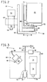
- Figure 2 is a schematic elevation view of the right camera assembly of the apparatus of Figure 1, showing a camera and an offset adjustment assembly.
- Figure 3 is a schematic elevation view of the left camera assembly of the apparatus of Figure 1, showing a camera, a light assembly, and a plotting pen assembly.
- Figure 1 illustrates an apparatus 10 for mounting a plurality of printing plates 12, e.g., flexographic printing plates, onto a carrier sheet 14, each plate 12 having a first and a second registration mark thereon.
- the apparatus 10 comprises a moveable table 16 on top of which the carrier sheet 14 is mounted, a first camera assembly 18 adjacent to table 16 and moveably attached to a guide supporting member 22, and a second camera assembly 20 adjacent the table 16 and moveably attached to the guide supporting member 22.
- the first camera assembly 18 is connected to a first TV-monitor 24 in a first display unit 26 for viewing the first registration marks
- the second camera assembly 20 is connected to a second TV-monitor 28 in a second display unit 30 for viewing the second registration marks.
- the first and second TV-monitors 24 and 26 are connected, respectively, to the first and second camera assemblies 18 and 20 via a motion controller 32.
- the apparatus 10 further includes means connected to the first and the second camera assemblies 18 and 20 for independently moving each assembly 18 and 20 relative to the table 16.
- the motion controller 32 is also connected to the moving means for sending moving signals thereto, the motion controller 32 generating at least two moving signals over lines 34 and 36 corresponding to the two registration marks for each plate 12.
- the moving signals generated by the motion controller 32 are controlled either from a preprogrammed memory card in the motion controller 32 or from a software program run by a computer 38 connected thereto.
- the moveable table 16 is slideably mounted over a stationary base (not shown) using guide blocks having ball raceways over a pair of grooved rails (not shown), which are located on top of the stationary base to provide movement of the table 16 in a direction perpendicular to the guide supporting member 22, hereinafter called the y-direction.
- the guide supporting member 22 is secured at its ends to the stationary base by end supports 40 and at a level above the table 16 and parallel thereto.
- the guide supporting member 22 includes a first threaded shaft 42 journaled within a threaded guide bracket attached to the first camera assembly 18 so that the first camera assembly 18 is caused to move over the table 16 parallel to the guide supporting member 22 when the first threaded shaft 40 is rotated.
- a second threaded shaft 44 is connected similarly to the second camera assembly 20. Both the first and the second shafts 42 and 44 are rotated by DC servo motors (not shown) located within the end supports 40 which are connected to and controlled by the moving signals received over lines 34 and 36 from the motion controller 32.
- a third threaded shaft (not shown) provides movement of the table 16 in the y-direction, this movement being independent of movement of the first and second camera assemblies 18 and 20 in the x-direction.
- the third shaft is rotated by a DC servo motor which also is connected to and controlled by a moving signal received over line 46 from the motion controller 32.
- the moving signals can be generated manually by use of a joystick 48 instead of preprogrammed coordinates as described below.
- the table 16 is adapted along its front x-direction edge to accurately locate a positioning bar 50, also extending in the x-direction.
- FIG. 2 illustrates the second camera assembly 20 previously described as mounted and moveable in the x-direction over the table 16 which is moveable in the y-direction.
- the second camera assembly 20 includes a camera 52, a camera lens 54, a window 56 and an offset adjustment assembly 58.
- the second camera assembly 20 also includes a preregistration light assembly (not shown) which is the same as the preregistration light assembly 80 described below in detail in association with the first camera assembly 18.
- the camera 52 and lens 54 are mounted to a camera mounting bracket 62 on the offset adjustment assembly 58 with a clamp 64 so that the camera 52 and lens 54 are directed toward the cable 16.
- the window 56 is attached to the lens 54 to prevent dust from contaminating the lens 54.
- the lens 54 of the camera 52 is focused upon the carrier sheet 14 (or the registration mark of the particular plate).
- the offset adjustment assembly 58 includes a moveable stage 66 for the camera mounting bracket 62 having the camera 52 and lens 54 mounted thereto.
- the stage 66 is mounted to a linear actuator 68 including the threaded guide bracket attached to the first threaded shaft 42 of the guide supporting member 22, which cooperatively function as means for moving the threaded guide bracket along a linear bearing 70 in the x-direction.
- the moveable stage 66 has a rotary encoder and a motor (not shown) which permits motion of the camera 52 in the y-direction.
- the offset adjustment assembly 58 is particularly useful when one or more plates 12 are remounted to the carrier sheet 14 or one or more additional plates 12 are mounted to the carrier sheet 14 subsequent to the original mounting operation. It is very difficult to remount single plates from "old" carrier sheets which have been in use for some time at the customer. Most of these "old" carrier sheets have been mounted without the help of electronic systems and therefore not all of these old mounts are real parallel.
- the offset function of one camera permits the mounting of new plates in exactly the same position as the old plates even though such plates were not 100% in parallel.
- the offset adjustment assembly 58 permits the operator to adjust the coordinate of the camera 52 in the second camera assembly 20 in the y-direction to properly register the remounted or new plate.
- the offset adjustment assembly 58 retains the adjustment offset for subsequent mounting of the corresponding plates on the other carrier sheets and therefore does not need to be reset or reestablished for each subsequent mounting of a plate.
- the first camera assembly 18 is similar to the above-described second camera assembly 20 without the offset adjustment assembly 58, so that the camera mounting bracket 60 is attached directly to the threaded guide bracket connected to the second threaded shaft 44.
- each camera assembly 18 and 20 also has a linear encoder 72, e.g., Anilam linear scales, connected to the motion controller 32 for measuring the precise position of each camera assembly 18 and 20 along the x-axis.
- the moveable table 16 includes a rotary encoder (not shown) connected to the motion controller 32 for measuring the precise position of the table 16 along the y-axis.
- each camera assembly 18 and 20 along both axes are transmitted from the motion controller 32 and displayed respectively on the first and second display units 26 and 30 which show numerical values for the x- and y-position coordinates of the camera assemblies 18 and 20 relative to the moveable table 16.
- the motion controller 32 retains the coordinate positions of the table 16 and the camera assemblies 18 and 20 so that if the table 16 is moved during the mounting operation, the table 16 will automatically return back to the desired y-coordinate position.
- FIG. 3 illustrates the first camera assembly 18 previously described as mounted and moveable in the x-direction over the table 16 which is moveable in the y-direction.
- the first camera assembly 18 includes a camera 74, a camera lens 76, a window 78, a preregistration light assembly 80, and a plotting pen assembly 82.
- the camera 74, lens 76, and window 78 are the same as described above for the second camera assembly 20 with the exception that the camera 74 and lens 76 are not mounted to an offset adjustment assembly 58 but are mounted to a camera mounting bracket 60 attached directly to the threaded guide bracket connected to the second threaded shaft 44.
- the preregistration light assembly 80 includes a light focusing lens 84 attached to a flexible fiber optic cable 86.
- the fiber optic cable 86 is attached to a light source (not shown), such as a quartz halogen optic illuminator, located on the guide supporting member 22.
- the light focusing lens 84 is held in place by a clamp 88 to the camera mounting bracket 60, and is positioned to shine light on the area on the carrier sheet 14 directly beneath the lens 76 and camera 74.
- the preregistration light assembly 80 illuminates the area on the carrier sheet 14 as well as the registration mark on the plate 12 at the location of the x- and y-coordinates for the particular registration mark.
- the first camera assembly 18 also includes a preregistration light assembly 80 as described but not shown.
- the first camera assembly 18 includes an opening 90 for positioning a pen 92 of the plotting pen assembly 82.
- the plotting pen assembly 82 includes the plotting pen 92 attached to a moveable rod 94 having a solenoid plunger 96 that is linked to a tubular pull-type solenoid 98.
- the pen 92 is a conventional pen used for plotting in automatic plotters and can be obtained from Hewlett Packard for example. When not in use, the pen 92 is in a retracted position as shown.
- the pen 92 is manually pulled down into a ready position at which the solenoid plunger 96 enters the solenoid 98.
- the solenoid 98 is activated and the pen 92 is moved to contact the carrier sheet 14.
- the first camera assembly 18 and the table 17 are moved to draw lines on the carrier sheet 14 upon activation by an operator selecting the appropriate file on the computer 38 of the present apparatus.
- Each camera assembly 18 and 20 forms, respectively, part of a separate video imaging system including the first and second display units 26 and 30 connected to the cameras 52 and 74.
- Each display unit 26 and 30 includes, respectively, the TV-monitors 24 and 28 connected to electronic cross-line generators (not shown) which produce on the TV-monitor screens a cross-hair image comprising vertical and horizontal lines. The intersection of the vertical and horizontal lines coincides precisely with the portion of the printing plate 12, i.e., registration mark, positioned directly beneath the center of the camera lens 54 and 76.
- the TV-cameras 52 and 74 typically produce a 25X magnification of the target area of the printing plate 12.
- the display units 26 and 30 also comprise numerical or digital displays 100 and 102 which read-out the x- and y-position coordinates of the registration mark.
- the technology used to generate the cross-hairs, display the received image and read-out the coordinate position of the camera is well known in the art.
- the cross-line generators contain a character generator for displaying information on the TV-monitors 24 and 28 in the form of alpha/numeric characters, e.g., A1, A2, ... B1, B2 ..., which correspond to the first and second registration marks for each printing plate 12 being mounted on the carrier sheet 14.
- the character generator receives information from the motion controller 32 and computer 38 as to which plate 12 should be mounted next.
- the camera assemblies 18 and 20 and respective display units 26 and 30, interconnected by the motion controller 32, provide an optical system enabling accurate positioning of the plates 12 on the carrier sheet 14 supported on the moveable table 16.
- a typical process used for the above-described flexographic printing plate mounting apparatus 10 is described below in the context of a corrugated container, e.g., a box.
- the first step in the process is the preparation of the mechanicals for each color to be printed.
- the mechanicals are full scale representations of the artwork to be printed, including all registration marks, superimposed on a layout of the unfolded, flat container, i.e., the substrate to be printed.
- the artwork, including registration marks, and container layout are generated and/or manipulated and then stored electronically in files typically in a pre-press computer.
- the artwork specialist determines the position of the plate relative to a predetermined zero position on the carrier sheet 14 and the position of a first registration mark and a second registration mark for the plate 12 relative to the carrier sheet 14.
- the position and registration marks for each plate 12 are stored electronically.
- die cut lines and fold lines associated with the layout of the container are stored electronically.
- the electronically stored artwork, including the registration marks is used to generate a mask which is used to form the relief pattern in the plate 12.
- a carrier sheet 14 is placed on the moveable table 16.
- the carrier sheet 14 is generally a heavy-gage flexible plastic material.
- a typical carrier sheet 14 is made of polyester and has a thickness in the range of 0.10 mm to 5.0 mm.
- the carrier sheet 14 is positioned on the table 16 using the positioning bar 50.
- the bar 50 can be a MATTHEW® lock or similar positioning device. In some cases, special clamping devices built into the printing cylinder are used to hold the carrier sheet 14 in place during printing. When these are used, it is advantageous to have the same type of clamping device as that used for the bar 50.
- the carrier sheet 14 can also be positioned using register holes and mounting pins.
- the pins or bar 50 can be permanently or removably attached to the table 16.
- the carrier sheet 15 is kept from moving by use of, for examble, flat weights or vacuum holddown.
- the table 16 using vacuum holddown may have several zones in order to accomodate different size carrier sheets.
- a mounter operator retrieves the recorded plate position and registration marks from the pre-press computer which is received in a file on the computer 38 for the mounting apparatus 10.
- Each of the camera assemblies 18 and 20 is moved independently over the moveable table 16 to a position which is the predetermined zero point. This can be one of the corners of the carrier sheet 14 at the leading edge, the center point of the carrier sheet 14 at the leading edge, etc.
- the movement of the camera assemblies 18 and 20 relative to the table 16 is accomplished by moving the table 16 along the grooved rails in the y-direction and also moving the camera assemblies 18 and 20 along the guide supporting member 22 in the x-direction.
- the table 16 is moved in the y-direction and the camera assemblies 18 and 20 are moved along the guide supporting member 22, in the x-direction until each camera assembly 18 and 20 is at the recorded x- and y-coordinates for the respective registration mark.
- the first camera assembly 18, in response to a first moving signal from the motion controller 32, is moved along the guide supporting member 22 until at the position having the x- and y-coordinates recorded for the first registration mark for the first plate 12, and the second camera assembly 20, in response to a second signal from the motion controller 32, is moved along the guide supporting member 22 until at the position having the x- and y-coordinates recorded for the second registration mark.
- the camera assemblies 18 and 20 are locked into place using locking means (not shown).
- the preregistration light assembly 80 in each camera assembly 18 and 20 illuminates the carrier sheet 14 in the location of the respective registration marks for the first printing plate 12.
- Stickyback tape is applied to the non-printing side (non-relief) of the plate 12. It is preferred during mounting that the stickyback tape is covered with an easy-release protective sheet, e.g., waxy paper, and a strip of the stickyback tape central to the plate 12 is not covered to reveal the adhesive.
- the first printing plate 12 is moved into position above the carrier sheet 14 with the non-relief side toward the carrier sheet 14 and the relief side including first and second registration marks under the preregistration light assembly 80.
- the plate 12 is then located on the carrier sheet 14, so that the First registration mark in the plate 12 is illuminated by the light assembly 80 of the first camera assembly 18 and aligns with the cross-hair marks shown on the screen of the first TV-monitor 24, and so that the second registration mark in the plate 12 is illuminated by the light assembly 80 of the second camera assembly 20 and aligns with the cross-hair marks shown on the screen of the second TV-monitor 28.
- the first plate 12 is pressed into place onto the carrier sheet 14 to adhere along the exposed adhesive area.
- the easy release sheet on each side of the adhered area of the first plate 12 is carefully removed from the plate and the remaining area of the plate 12 is pressed into place to adhere to the carrier sheet 14.
- the registration coordinates for a second plate are retrieved, the camera assemblies 18 and 20 and the table 16 are moved into place, the second plate is prepared as described above. This is repeated for all of the remaining plates to be mounted on the carrier sheet 14. It is possible during the plate mounting process that the table 16 may move off from the desired registration coordinates. In this case, the motion controller 32 which retains the y-coordinate for the current plate being mounted, signals to have the table 16 return to the correct y-coordinate location.
- the present invention offers advantages in that multiple plates can be mounted onto a carrier sheet 14 with the need for only two camera assemblies 18 and 20.
- the layout of the unfolded flat container is drawn onto the carrier sheet 14 which shows, for example, the distorted die cut lines and distorted fold lines of the container.
- the first camera assembly 18 is positioned at the zero location.
- the pen 92 in the plotting pen assembly 82 is moved so that the pen 92 contacts the carrier sheet 14.
- the table 16 and/or the first camera assembly 18 is then moved so that the pen 92 draws the die cut lines, fold lines, and any other relevant markings of the container onto the carrier sheet 14. Marking the carrier sheet 14 assures the printer prior to printing that the plates are positioned properly on the carrier sheet 14 relative to the desired box to be printed, and helps the printer to visualize the printed box.
- each of the plates 12 After all the plates 12 have been mounted to the carrier sheet 14, perimeter edges of each of the plates 12 are sealed into place with an edge sealant to prevent the plate 12 from peeling from the carrier sheet 14 during handling and/or printing.
- the carrier sheet 14 with the plates 12 is then mounted onto a printing cylinder.
- the positioning bar 50 can be used to mount the carrier sheet 14 to the cylinder.
- the sheets are usually held to the cylinder with tension bands or with special clamping devices built into the cylinder.
Abstract
Description
Claims (16)
- An apparatus for mounting a plurality of plates onto a carrier sheet, each plate having a first and a second registration mark thereon, comprising:a table mounted on a stationary base;a first camera assembly adjacent the cable and moveably attached to a support, said first camera assembly connected to a first video monitor for viewing said first registration marks;a second camera assembly adjacent the table and moveably attached to said support, said second camera assembly connected to a second video monitor for viewing said second registration marks;means connected to said first and said second camera assemblies for independently moving each camera assembly relative to said table; anda motion controller connected to said moving means for sending moving signals thereto, said motion controller including means for generating at least two moving signals corresponding to said two registration marks for each plate.
- An apparatus in accordance with Claim 1 wherein said first and second camera assemblies are adapted to move along said support in a first direction, and wherein said second camera assembly includes an, offset adjustment assembly comprising a moveable stage adapted to move along a second direction orthogonal to said first direction.
- An apparatus in accordance with Claim 2 wherein said table has means connected thereto for moving said table relative to said stationary base along said second direction.
- An apparatus in accordance with Claim 1 wherein said first and said second camera assemblies each comprise a camera and a preregistration light assembly, and wherein said first camera assembly includes a plotting pen assembly adapted to draw a marking on said carrier sheet.
- An apparatus in accordance with Claim 4 wherein said plotting pen assembly comprises a plotting pen attached to a moveable rod activated by a solenoid plunger.
- An apparatus in accordance with Claim 1 wherein each moving means comprises a linear actuator for receiving said moving signals, and an encoder for measuring the distance each camera assembly or table moves along said first and said second directions.
- An apparatus in accordance with Claim 1 further comprising a first and a second digital display connected to said motion controller for showing, respectively, the position coordinates of said first and said second camera assemblies along said first and second directions.
- An apparatus in accordance with Claim 1 wherein said generating means comprises a software program run by a computer connected to said motion controller.
- An apparatus in accordance with Claim 1 wherein said generating means comprises a preprogrammed memory card contained in said motion controller.
- A method for mounting a plurality of plates onto a carrier sheet, each plate having a first and a second registration mark thereon, comprising:(a) placing said carrier sheet on a table mounted on a stationary base;(b) sending first moving signals from a motion controller to means for moving said table and to means for moving a first camera assembly to first position coordinates corresponding to said first registration mark for a first plate being mounted, said first camera assembly moveably attached to a support adjacent said table id connected to a first video monitor;(c) sending second moving signals from said motion controller to means for moving a second camera assembly to second position coordinates corresponding to said second registration mark for said first plate being mounted, said second camera assembly moveably attached to said support adjacent said table and connected to a second video monitor;(d) moving said table and said first and said second camera assemblies in response to said rust and said second moving signals so as to locate said first and said second camera assemblies, respectively, at said first and said second position coordinates;(e) positioning said first plate on said carrier sheet beneath said first and said second camera assemblies so that said first registration mark aligns with a cross-hair image on said first video monitor id said second registration mark aligns with a cross-hair image on said second video monitor; and(f) mounting said first plate onto said carrier sheet after said positioning step.
- A method in accordance with Claim 10 wherein steps (b) through (f) are repeated, respectively, for subsequent plates being mounted on said carrier sheet.
- A method in accordance with Claim 10 wherein the steps of sending said first and said second moving signals from said motion controller is performed by generating said first and said second signals from a software program run by a computer connected to said motion controller.
- A method in accordance with Claim 10 wherein the steps of sending said first and said second moving signals from said motion controller is performed by generating said first and said second signals from a preprogrammed memory card contained in said motion controller
- A method in accordance with Claim 10 wherein said first and said second camera assemblies are adapted to move along said support in a first direction, wherein said second camera assembly includes a moveable stage adapted to move along a second direction orthogonal to said first direction, and wherein said method further comprises moving said second camera assembly along said second direction.
- A method in accordance with Claim 10 wherein said first camera assembly includes a plotting pen assembly containing a plotting pen, and wherein said method further comprises the step of drawing a marking on said carrier sheet with said plotting pen.
- A method in accordance with Claim 10 wherein each moving means comprises a linear actuator for receiving said moving signals.
Applications Claiming Priority (2)
| Application Number | Priority Date | Filing Date | Title |
|---|---|---|---|
| US898098 | 1997-07-22 | ||
| US08/898,098 US5850789A (en) | 1997-07-22 | 1997-07-22 | Method and apparatus for mounting printing plates |
Publications (3)
| Publication Number | Publication Date |
|---|---|
| EP0893254A2 true EP0893254A2 (en) | 1999-01-27 |
| EP0893254A3 EP0893254A3 (en) | 1999-06-16 |
| EP0893254B1 EP0893254B1 (en) | 2001-12-19 |
Family
ID=25408943
Family Applications (1)
| Application Number | Title | Priority Date | Filing Date |
|---|---|---|---|
| EP98111135A Expired - Lifetime EP0893254B1 (en) | 1997-07-22 | 1998-06-17 | Method and apparatus for registration mounting printing plates |
Country Status (4)
| Country | Link |
|---|---|
| US (1) | US5850789A (en) |
| EP (1) | EP0893254B1 (en) |
| JP (1) | JP4319267B2 (en) |
| DE (1) | DE69803013T2 (en) |
Cited By (5)
| Publication number | Priority date | Publication date | Assignee | Title |
|---|---|---|---|---|
| EP1445097A1 (en) * | 2002-01-15 | 2004-08-11 | Agfa Corporation | Verifying correct mounting of a printing plate on an external drum imaging machine |
| EP1543966A1 (en) * | 2003-12-19 | 2005-06-22 | Creo Inc. | Method and apparatus for detecting the seam of a flexographic printing plate precursor |
| WO2006082601A1 (en) * | 2005-02-04 | 2006-08-10 | Sys Tec S.R.L. | Machine for flexographic printing lines |
| EP2532522A1 (en) * | 2011-06-06 | 2012-12-12 | AV Flexologic B.V. | Method and device for positioning a printing plate in its register position |
| NL2009341C2 (en) * | 2012-08-22 | 2014-02-25 | Color Control B V | DEVICE AND METHOD FOR CORRECTING THE EFFECTS OF A DEROGATION FROM THE POSITION OF A MOVABLE CAMERA IN A POSITIONING DEVICE FOR POSITIONING FLEXIBLE PRESSURE PLATES ON A SUPPORT. |
Families Citing this family (35)
| Publication number | Priority date | Publication date | Assignee | Title |
|---|---|---|---|---|
| NL1007631C2 (en) * | 1997-11-27 | 1999-06-14 | Av Flexologic Bv | Method and device for positioning printing plates. |
| JP3190956B2 (en) * | 1998-11-02 | 2001-07-23 | 株式会社金田機械製作所 | Manufacturing method of printing plate for newspaper printing |
| US6282027B1 (en) * | 1999-03-26 | 2001-08-28 | Vari-Lite, Inc. | Zoomable beamspreader with matched optical surfaces for non-imaging illumination applications |
| JP3357024B2 (en) * | 1999-04-19 | 2002-12-16 | リョービ株式会社 | Printing plate processing apparatus and register mark position detecting method thereof |
| US6117615A (en) * | 1999-07-28 | 2000-09-12 | E. I. Du Pont De Nemours And Company | Method for mounting multiple printing elements onto a cylindrical element |
| US6298783B1 (en) * | 1999-10-29 | 2001-10-09 | Fargo Electronics, Inc. | Printhead alignment device and method of use |
| JP2001261196A (en) * | 2000-03-15 | 2001-09-26 | Fuji Photo Film Co Ltd | Sheet positioning method and device |
| JP3407112B2 (en) * | 2000-10-30 | 2003-05-19 | 株式会社東京機械製作所 | Plate mounting position determination device |
| KR100387604B1 (en) * | 2001-03-05 | 2003-06-18 | 주식회사 씨엔피테크 | Printing Plate Setting Apparatus Using Panel PC And Stepping Motor |
| US6823793B2 (en) * | 2003-01-06 | 2004-11-30 | Esko Graphics, Nv | Method and apparatus for mounting flexographic plate segments |
| US7456379B2 (en) * | 2003-02-03 | 2008-11-25 | Kodak Graphic Communications Canada Company | Printing plate registration and optical alignment device including locating at least a part of a reference edge in at least one digital camera image |
| NL1023431C2 (en) * | 2003-05-14 | 2004-11-16 | Av Flexologic Bv | Regulated positioning device for flexible printing plates. |
| US20050125980A1 (en) * | 2003-12-11 | 2005-06-16 | Rakow Donald E.Jr. | System and method of constructing wire wrap well screens |
| EP1742797B1 (en) * | 2004-05-04 | 2012-01-11 | SYS Tec. S.R.L. | Method and machine for aligning flexographic printing plates on printing cylinders |
| ITBO20040749A1 (en) * | 2004-12-02 | 2005-03-02 | Bieffebi Spa | MACHINE FOR THE ASSEMBLY OF A FLEXOGRAPHIC CLICHE REGISTER WITH A VIRTUAL INFORMATION SYSTEM |
| EP1957270B1 (en) * | 2005-10-17 | 2015-04-15 | Gerald J. Gartner | Method for mounting a plate to an adhesive member |
| US7511732B2 (en) * | 2006-03-30 | 2009-03-31 | Crucible Technologies, Llc | Assembly and method for securing an endoscope to a digital camera |
| US7819060B2 (en) | 2007-04-13 | 2010-10-26 | E.I. Du Pont De Nemours And Company | Method for mounting cylindrically-shaped printing forms |
| US8236479B2 (en) | 2008-01-23 | 2012-08-07 | E I Du Pont De Nemours And Company | Method for printing a pattern on a substrate |
| US8129091B2 (en) * | 2008-05-28 | 2012-03-06 | E.I. Du Pont De Nemours And Company | Method for preparing a composite printing form using a template |
| US8034540B2 (en) * | 2008-07-31 | 2011-10-11 | Eastman Kodak Company | System and method employing secondary back exposure of flexographic plate |
| US20100186234A1 (en) | 2009-01-28 | 2010-07-29 | Yehuda Binder | Electric shaver with imaging capability |
| ITBS20090057A1 (en) * | 2009-03-24 | 2010-09-25 | Sys Tec S R L | DEVICE AND METHOD OF ASSEMBLY OF PRINTING SHEETS |
| US8263314B2 (en) * | 2009-08-14 | 2012-09-11 | E I Du Pont De Nemours And Company | Method for preparing a composite printing form |
| PE20130052A1 (en) | 2009-11-03 | 2013-02-04 | Orica Explosives Tech Pty Ltd | CONNECTOR |
| EP2428360B1 (en) * | 2010-09-10 | 2017-03-15 | Bobst Bielefeld GmbH | Method and mounter for mounting printing plates |
| CA2834037C (en) * | 2011-04-28 | 2020-01-28 | Leader Engineering-Fabrication, Inc. | Method and apparatus for mounting a printing plate |
| US20140000516A1 (en) * | 2012-06-29 | 2014-01-02 | Toyota Motor Engineering & Manufacturing North America, Inc. | Digital point marking transfer |
| DE102012214824A1 (en) * | 2012-08-21 | 2014-02-27 | Ball Europe Gmbh | Method and device for aligning printing plates on printing cylinders |
| US20140096696A1 (en) * | 2012-10-05 | 2014-04-10 | Nela Ternes Register Group, Inc. | Open loop control system and methods for color print registration |
| CN109690417B (en) | 2016-07-21 | 2021-08-06 | 埃斯科绘图成像有限责任公司 | System and method for mounting printing plate on carrier |
| EP3672809B1 (en) * | 2017-08-24 | 2022-01-19 | Esko-Graphics Imaging GmbH | Printing plate segment mounting system and method |
| JP6691080B2 (en) | 2017-08-25 | 2020-04-28 | 矢崎総業株式会社 | Conductor connection structure of plate-shaped cable |
| CN110027332B (en) * | 2018-01-11 | 2021-01-26 | 昆山瑞咏成精密设备有限公司 | Concave surface high-precision repeated overprinting method and blind hole printing machine |
| EP3794811B1 (en) | 2019-05-17 | 2022-02-16 | Esko-Graphics Imaging GmbH | System and method for storing interrelated image information in a print job file |
Citations (8)
| Publication number | Priority date | Publication date | Assignee | Title |
|---|---|---|---|---|
| EP0089015A1 (en) * | 1982-03-16 | 1983-09-21 | Windmöller & Hölscher | Method of registering and attaching printing plates on the plate cylinder of flexographic multicolour printing machines |
| US4707930A (en) * | 1986-10-28 | 1987-11-24 | Sakata Shokai, Ltd. | Apparatus for mounting a relief plate for letterpress printing |
| WO1988006522A1 (en) * | 1987-02-27 | 1988-09-07 | Allan Banke | Method for mounting a plate on a cylinder and device for carrying out the method |
| DE4429565A1 (en) * | 1993-08-24 | 1995-03-02 | Du Pont | Device for drilling holes |
| US5488781A (en) * | 1994-12-13 | 1996-02-06 | Av Flexologic B.V. | Positioning apparatus for printing plates |
| EP0728580A1 (en) * | 1995-02-24 | 1996-08-28 | BIEFFEBI S.p.A. | Machine for mounting flexible printing plates on plate-holder cylinders of flexographic printing machines and for printing proofs |
| JPH08224857A (en) * | 1994-11-17 | 1996-09-03 | Kamo Denki Kenkyusho:Kk | Forming method for press plate having punched holes for setting to press |
| EP0749829A1 (en) * | 1995-06-22 | 1996-12-27 | Polygram Manufacturing & Distribution Centres GmbH | Method for exact alignment of a printing image on a geometrically correct position in a printing machine |
Family Cites Families (12)
| Publication number | Priority date | Publication date | Assignee | Title |
|---|---|---|---|---|
| DD147974B1 (en) * | 1980-01-31 | 1987-03-25 | Joerg Wunderlich | DEVICE FOR POSITIONING AN OBJECT ON A TRAEGER |
| DE3135442A1 (en) * | 1980-09-09 | 1982-06-16 | Protocol Engineering Ltd., Berkhamsted, Hertfordshire | METHOD FOR FIXING AT LEAST ONE FLEXIBLE PRINT PLATE IN A ROTARY PRESS PRESS OR THE LIKE |
| DE3633855A1 (en) * | 1986-10-04 | 1988-04-14 | Heidelberger Druckmasch Ag | METHOD AND DEVICE FOR FIXING CORRECTION |
| JP2757036B2 (en) * | 1989-08-26 | 1998-05-25 | 株式会社新川 | Marking method and device |
| US5132911A (en) * | 1989-12-27 | 1992-07-21 | Leader Engineering Fabrication, Inc. | Apparatus for mounting and proofing printing plates |
| US5058287A (en) * | 1990-08-21 | 1991-10-22 | Richard Harley | Register system and method for flexographic printing plates |
| US5136948A (en) * | 1990-10-31 | 1992-08-11 | Kabushiki Kaisha Shinkawa | Marking method and apparatus |
| GB9104705D0 (en) * | 1991-03-06 | 1991-04-17 | Lowe John M | Vision system |
| DE4208179C2 (en) * | 1992-03-12 | 1996-02-29 | Koenig & Bauer Albert Ag | Method and device for the correct alignment and application of clichés on the lateral surfaces of forme cylinders |
| US5317971A (en) * | 1992-08-26 | 1994-06-07 | Deye Jr Charles E | Pin register mounter and method of mounting flexographic plates |
| GB9323978D0 (en) * | 1993-11-22 | 1994-01-12 | Dek Printing Machines Ltd | Alignment systems |
| DE4401269A1 (en) * | 1994-01-18 | 1995-07-20 | Roland Man Druckmasch | Method and device for the correct positioning of printing form sleeves |
-
1997
- 1997-07-22 US US08/898,098 patent/US5850789A/en not_active Expired - Lifetime
-
1998
- 1998-06-17 EP EP98111135A patent/EP0893254B1/en not_active Expired - Lifetime
- 1998-06-17 DE DE69803013T patent/DE69803013T2/en not_active Expired - Lifetime
- 1998-07-22 JP JP20679798A patent/JP4319267B2/en not_active Expired - Fee Related
Patent Citations (8)
| Publication number | Priority date | Publication date | Assignee | Title |
|---|---|---|---|---|
| EP0089015A1 (en) * | 1982-03-16 | 1983-09-21 | Windmöller & Hölscher | Method of registering and attaching printing plates on the plate cylinder of flexographic multicolour printing machines |
| US4707930A (en) * | 1986-10-28 | 1987-11-24 | Sakata Shokai, Ltd. | Apparatus for mounting a relief plate for letterpress printing |
| WO1988006522A1 (en) * | 1987-02-27 | 1988-09-07 | Allan Banke | Method for mounting a plate on a cylinder and device for carrying out the method |
| DE4429565A1 (en) * | 1993-08-24 | 1995-03-02 | Du Pont | Device for drilling holes |
| JPH08224857A (en) * | 1994-11-17 | 1996-09-03 | Kamo Denki Kenkyusho:Kk | Forming method for press plate having punched holes for setting to press |
| US5488781A (en) * | 1994-12-13 | 1996-02-06 | Av Flexologic B.V. | Positioning apparatus for printing plates |
| EP0728580A1 (en) * | 1995-02-24 | 1996-08-28 | BIEFFEBI S.p.A. | Machine for mounting flexible printing plates on plate-holder cylinders of flexographic printing machines and for printing proofs |
| EP0749829A1 (en) * | 1995-06-22 | 1996-12-27 | Polygram Manufacturing & Distribution Centres GmbH | Method for exact alignment of a printing image on a geometrically correct position in a printing machine |
Non-Patent Citations (1)
| Title |
|---|
| PATENT ABSTRACTS OF JAPAN vol. 97, no. 1, 31 January 1997 & JP 08 224857 A (KAMO DENKI KENKYUSHO : KK), 3 September 1996 * |
Cited By (8)
| Publication number | Priority date | Publication date | Assignee | Title |
|---|---|---|---|---|
| EP1445097A1 (en) * | 2002-01-15 | 2004-08-11 | Agfa Corporation | Verifying correct mounting of a printing plate on an external drum imaging machine |
| EP1543966A1 (en) * | 2003-12-19 | 2005-06-22 | Creo Inc. | Method and apparatus for detecting the seam of a flexographic printing plate precursor |
| WO2006082601A1 (en) * | 2005-02-04 | 2006-08-10 | Sys Tec S.R.L. | Machine for flexographic printing lines |
| EP2532522A1 (en) * | 2011-06-06 | 2012-12-12 | AV Flexologic B.V. | Method and device for positioning a printing plate in its register position |
| US9308716B2 (en) | 2011-06-06 | 2016-04-12 | Av Flexologic B.V. | Method and device for placing a printing plate in its register position |
| NL2009341C2 (en) * | 2012-08-22 | 2014-02-25 | Color Control B V | DEVICE AND METHOD FOR CORRECTING THE EFFECTS OF A DEROGATION FROM THE POSITION OF A MOVABLE CAMERA IN A POSITIONING DEVICE FOR POSITIONING FLEXIBLE PRESSURE PLATES ON A SUPPORT. |
| EP2700503A1 (en) * | 2012-08-22 | 2014-02-26 | Color Control B.V. | Device and method for correcting the position of a movable camera for positioning flexible printing plates on a carrier |
| US9930205B2 (en) | 2012-08-22 | 2018-03-27 | Color Control B.V. | Apparatus and method for correcting the effects of a deviation of the position of a movable camera in a positioning apparatus for the positioning of flexible printing plates on a carrier |
Also Published As
| Publication number | Publication date |
|---|---|
| EP0893254B1 (en) | 2001-12-19 |
| DE69803013T2 (en) | 2002-07-18 |
| EP0893254A3 (en) | 1999-06-16 |
| DE69803013D1 (en) | 2002-01-31 |
| JPH1177983A (en) | 1999-03-23 |
| US5850789A (en) | 1998-12-22 |
| JP4319267B2 (en) | 2009-08-26 |
Similar Documents
| Publication | Publication Date | Title |
|---|---|---|
| US5850789A (en) | Method and apparatus for mounting printing plates | |
| US5439328A (en) | Single-head drill with video attachment | |
| EP0417080B1 (en) | Device for mounting a plate on a cylinder | |
| AU641576B2 (en) | Screen printing plate and method and apparatus for its manufacture | |
| US6948432B2 (en) | Method and apparatus for mounting flexographic plate segments | |
| US4827626A (en) | Method and apparatus for register correction | |
| US4833985A (en) | Apparatus for matching register marks and punching U-holes for press plate | |
| EP2701910B1 (en) | Method and apparatus for mounting a printing plate | |
| EP3672809B1 (en) | Printing plate segment mounting system and method | |
| JPS58177359A (en) | Method of setting up printing block at accurate position on form cylinder of flex graph printer for polychrome printing | |
| EP1241004B1 (en) | A screen printer and a method for setting a screen plate | |
| US4707930A (en) | Apparatus for mounting a relief plate for letterpress printing | |
| US5585886A (en) | Apparatus for printing a photosensitive material and positioning device | |
| JPS63207646A (en) | Plate registering method in screen printing machine | |
| US5058287A (en) | Register system and method for flexographic printing plates | |
| JP2006240124A (en) | Frame positioning method for screen printing machine, and screen printing machine | |
| JPS6311660B2 (en) | ||
| JP3112581B2 (en) | Positioning device and printing device | |
| JPS6391253A (en) | Registering method of offset printer and its device | |
| KR100750515B1 (en) | Screen printer for fabricating flat panel display | |
| JP2679886B2 (en) | Film pasting device | |
| CA2051094A1 (en) | Print analysis system | |
| JPS61108555A (en) | Multicolor screen printing device | |
| JP3304252B2 (en) | Method of making a printing plate having punch holes for setting in a printing press | |
| JPH11138743A (en) | Screen printer and screen printing method |
Legal Events
| Date | Code | Title | Description |
|---|---|---|---|
| PUAI | Public reference made under article 153(3) epc to a published international application that has entered the european phase |
Free format text: ORIGINAL CODE: 0009012 |
|
| AK | Designated contracting states |
Kind code of ref document: A2 Designated state(s): DE FR GB IT NL |
|
| AX | Request for extension of the european patent |
Free format text: AL;LT;LV;MK;RO;SI |
|
| PUAL | Search report despatched |
Free format text: ORIGINAL CODE: 0009013 |
|
| AK | Designated contracting states |
Kind code of ref document: A3 Designated state(s): AT BE CH CY DE DK ES FI FR GB GR IE IT LI LU MC NL PT SE |
|
| AX | Request for extension of the european patent |
Free format text: AL;LT;LV;MK;RO;SI |
|
| RIC1 | Information provided on ipc code assigned before grant |
Free format text: 6B 41F 27/00 A, 6B 41F 27/12 B, 6B 41F 5/24 B, 6B 41F 27/14 B |
|
| 17P | Request for examination filed |
Effective date: 19990813 |
|
| AKX | Designation fees paid |
Free format text: DE FR GB IT NL |
|
| 17Q | First examination report despatched |
Effective date: 20000223 |
|
| GRAG | Despatch of communication of intention to grant |
Free format text: ORIGINAL CODE: EPIDOS AGRA |
|
| GRAG | Despatch of communication of intention to grant |
Free format text: ORIGINAL CODE: EPIDOS AGRA |
|
| GRAH | Despatch of communication of intention to grant a patent |
Free format text: ORIGINAL CODE: EPIDOS IGRA |
|
| GRAH | Despatch of communication of intention to grant a patent |
Free format text: ORIGINAL CODE: EPIDOS IGRA |
|
| GRAA | (expected) grant |
Free format text: ORIGINAL CODE: 0009210 |
|
| AK | Designated contracting states |
Kind code of ref document: B1 Designated state(s): DE FR GB IT NL |
|
| REG | Reference to a national code |
Ref country code: GB Ref legal event code: IF02 |
|
| REF | Corresponds to: |
Ref document number: 69803013 Country of ref document: DE Date of ref document: 20020131 |
|
| ET | Fr: translation filed | ||
| PLBE | No opposition filed within time limit |
Free format text: ORIGINAL CODE: 0009261 |
|
| STAA | Information on the status of an ep patent application or granted ep patent |
Free format text: STATUS: NO OPPOSITION FILED WITHIN TIME LIMIT |
|
| 26N | No opposition filed | ||
| PGFP | Annual fee paid to national office [announced via postgrant information from national office to epo] |
Ref country code: FR Payment date: 20100709 Year of fee payment: 13 |
|
| PGFP | Annual fee paid to national office [announced via postgrant information from national office to epo] |
Ref country code: IT Payment date: 20100616 Year of fee payment: 13 |
|
| PGFP | Annual fee paid to national office [announced via postgrant information from national office to epo] |
Ref country code: NL Payment date: 20100603 Year of fee payment: 13 |
|
| PGFP | Annual fee paid to national office [announced via postgrant information from national office to epo] |
Ref country code: GB Payment date: 20100616 Year of fee payment: 13 Ref country code: DE Payment date: 20100610 Year of fee payment: 13 |
|
| REG | Reference to a national code |
Ref country code: NL Ref legal event code: V1 Effective date: 20120101 |
|
| GBPC | Gb: european patent ceased through non-payment of renewal fee |
Effective date: 20110617 |
|
| PG25 | Lapsed in a contracting state [announced via postgrant information from national office to epo] |
Ref country code: IT Free format text: LAPSE BECAUSE OF NON-PAYMENT OF DUE FEES Effective date: 20110617 |
|
| REG | Reference to a national code |
Ref country code: FR Ref legal event code: ST Effective date: 20120229 |
|
| REG | Reference to a national code |
Ref country code: DE Ref legal event code: R119 Ref document number: 69803013 Country of ref document: DE Effective date: 20120103 |
|
| PG25 | Lapsed in a contracting state [announced via postgrant information from national office to epo] |
Ref country code: DE Free format text: LAPSE BECAUSE OF NON-PAYMENT OF DUE FEES Effective date: 20120103 Ref country code: FR Free format text: LAPSE BECAUSE OF NON-PAYMENT OF DUE FEES Effective date: 20110630 |
|
| PG25 | Lapsed in a contracting state [announced via postgrant information from national office to epo] |
Ref country code: NL Free format text: LAPSE BECAUSE OF NON-PAYMENT OF DUE FEES Effective date: 20120101 |
|
| PG25 | Lapsed in a contracting state [announced via postgrant information from national office to epo] |
Ref country code: GB Free format text: LAPSE BECAUSE OF NON-PAYMENT OF DUE FEES Effective date: 20110617 |