JP4313402B2 - Marching career - Google Patents
Marching career Download PDFInfo
- Publication number
- JP4313402B2 JP4313402B2 JP2007119679A JP2007119679A JP4313402B2 JP 4313402 B2 JP4313402 B2 JP 4313402B2 JP 2007119679 A JP2007119679 A JP 2007119679A JP 2007119679 A JP2007119679 A JP 2007119679A JP 4313402 B2 JP4313402 B2 JP 4313402B2
- Authority
- JP
- Japan
- Prior art keywords
- frame
- shoulder
- marching
- cushion
- carrier
- Prior art date
- Legal status (The legal status is an assumption and is not a legal conclusion. Google has not performed a legal analysis and makes no representation as to the accuracy of the status listed.)
- Active
Links
- 210000001015 abdomen Anatomy 0.000 claims description 12
- 230000037431 insertion Effects 0.000 description 10
- 238000003780 insertion Methods 0.000 description 10
- 238000009527 percussion Methods 0.000 description 7
- 230000037237 body shape Effects 0.000 description 6
- 239000000463 material Substances 0.000 description 6
- 239000002184 metal Substances 0.000 description 6
- 239000011347 resin Substances 0.000 description 4
- 229920005989 resin Polymers 0.000 description 4
- 229920002635 polyurethane Polymers 0.000 description 3
- 239000004814 polyurethane Substances 0.000 description 3
- 125000006850 spacer group Chemical group 0.000 description 3
- 230000003187 abdominal effect Effects 0.000 description 2
- 239000012141 concentrate Substances 0.000 description 2
- 239000013013 elastic material Substances 0.000 description 2
- 238000007664 blowing Methods 0.000 description 1
- 210000001217 buttock Anatomy 0.000 description 1
- 239000000969 carrier Substances 0.000 description 1
- 230000000694 effects Effects 0.000 description 1
- 229920001971 elastomer Polymers 0.000 description 1
- 230000007306 turnover Effects 0.000 description 1
Images


Classifications
-
- G—PHYSICS
- G10—MUSICAL INSTRUMENTS; ACOUSTICS
- G10G—REPRESENTATION OF MUSIC; RECORDING MUSIC IN NOTATION FORM; ACCESSORIES FOR MUSIC OR MUSICAL INSTRUMENTS NOT OTHERWISE PROVIDED FOR, e.g. SUPPORTS
- G10G5/00—Supports for musical instruments
- G10G5/005—Supports for musical instruments while playing, e.g. cord, strap or harness
Landscapes
- Physics & Mathematics (AREA)
- Engineering & Computer Science (AREA)
- Acoustics & Sound (AREA)
- Multimedia (AREA)
- Auxiliary Devices For Music (AREA)
Description
本発明は、マーチングドラム等の楽器を演奏者の前方で支持するマーチングキャリアに関する。 The present invention relates to a marching carrier for supporting a musical instrument such as a marching drum in front of a performer.
例えば、パレード等では、演奏者が、肩掛け式のマーチングキャリアにより支持されたマーチングドラム等の楽器を演奏する。この場合、演奏者は、停止して楽器を演奏するだけでなく、動きを伴いながら演奏することもある。このため、マーチングキャリアには、演奏者の身体に楽器を確実に支持することが要求される。こうした理由から、楽器を吊り下げて支持するベルト式のマーチングキャリアではなく、演奏者の両肩に掛けられるフック状の肩掛け部と、楽器を支持するプレート部とを一体化したものが主流となっている。 For example, in a parade or the like, a performer plays a musical instrument such as a marching drum supported by a shoulder-type marching carrier. In this case, the performer may not only stop and play the instrument, but also perform with movement. For this reason, marching carriers are required to reliably support musical instruments on the performer's body. For this reason, instead of a belt-type marching carrier that suspends and supports a musical instrument, a hook-shaped shoulder that can be hung on both shoulders of the performer and a plate that supports the musical instrument are the mainstream. ing.
しかし、一体型のマーチングキャリアの場合、楽器を確実に支持できる反面、ベルト式のマーチングキャリアのように、肩掛け部が演奏者の身体に沿って変形しない。このため、マーチングキャリアと演奏者との接触面積を十分に確保できず、楽器の荷重が演奏者の肩や背中といった特定の箇所に集中し、演奏者への負荷が大きくなるという問題があった。そこで、演奏者への負荷を小さくするため、演奏者の身体に合わせて肩掛け部の形状や位置等を調節可能なキャリアが提案されている。例えば、特許文献1には、上プレートと、上プレートの上端に回動可能に連結されたアームと、上プレートの下端に回動可能に連結された下プレートとを備えるキャリアが開示されている。特許文献2には、一対の肩掛け具を備え、両肩掛け具間の距離を変更可能なマーチングキャリアが開示されている。特許文献3には、フレームの上端に回動可能に連結された一対のストラップを備えたマーチングキャリアが開示されている。特許文献4には、肩掛け用ストラップの長さを変更可能なマーチングキャリアが開示されている。特許文献5には、背中クッション内にエアを吹き込むことにより、背中クッションの厚さを変更可能なマーチングキャリアが開示されている。
上記のキャリアにより演奏者が前方で楽器を支持する際、演奏者は、主として、キャリアとの接触部分である腹、背中及び肩といった各部位において楽器の荷重を受ける。しかしながら、上記各文献に開示のキャリアによれば、肩掛け部の角度や位置を調節できるものの、演奏者の背中や肩といった部位毎に別々に調節できるように形成されていない。このため、演奏者の背中や肩の形状によっては、これらの部位とキャリアとの接触面積を十分に確保できないことがある。特に、マーチングキャリアに支持される楽器の重量が大きい場合、演奏者の背中や肩等の特定の箇所に楽器の荷重が集中し、演奏者への負担が軽減されないという問題があった。 When the performer supports the musical instrument in the front by the carrier, the performer receives the load of the musical instrument mainly at each part such as the abdomen, back, and shoulder that is a contact portion with the carrier. However, according to the carrier disclosed in each of the above-mentioned documents, although the angle and position of the shoulder portion can be adjusted, it is not formed so that it can be adjusted separately for each part such as the back and shoulders of the performer. For this reason, depending on the shape of the performer's back and shoulders, the contact area between these parts and the carrier may not be sufficiently secured. In particular, when the weight of the musical instrument supported by the marching carrier is large, there is a problem that the load on the musical instrument is concentrated on specific places such as the back and shoulders of the performer and the burden on the performer cannot be reduced.
本発明は、このような問題に鑑みてなされたものであり、その目的は、演奏者の背中や肩における特定の箇所に楽器の荷重が集中することを抑止でき、演奏者への負担を軽減することのできるマーチングキャリアを提供することにある。 The present invention has been made in view of such problems, and its purpose is to reduce the burden on the performer by suppressing the concentration of the load of the instrument on a specific location on the performer's back or shoulder. It is to provide a marching carrier that can do this.
上記の目的を達成するために、請求項1に記載の発明は、演奏者の前方で楽器を支持するマーチングキャリアであって、演奏者の胴体の前面に当接されるキャリア本体と、キャリア本体の下部に装着され、楽器を支持する支持部材と、キャリア本体の上部に設けられ、演奏者の両肩に沿ってその前後に配置されるフレームと、フレームに対し回動可能に取着され、演奏者の両肩に当接される一対の肩クッションと、フレームに対し回動可能に取着され、演奏者の背中に当接される背中クッションとを備え、フレームに対する肩クッション及び背中クッションの角度が別々に調節可能であることを要旨とする。 In order to achieve the above object, the invention according to claim 1 is a marching carrier for supporting a musical instrument in front of a player, the carrier main body being in contact with the front surface of the player's torso, and the carrier main body A support member that supports the musical instrument, and is provided on the upper part of the carrier body, and is arranged on the front and back of the performer along both shoulders of the performer. A pair of shoulder cushions that are in contact with both shoulders of the performer and a back cushion that is rotatably attached to the frame and that is in contact with the back of the performer. The gist is that the angle can be adjusted separately.
同構成によれば、演奏者の肩や背中の形状に合わせて、フレームに対する肩クッションの角度と背中クッションの角度とを別々に調節することができる。これにより、演奏者の身体と肩クッション及び背中クッションとの接触面積を十分に確保することができる。よって、演奏者がその前方で楽器を支持する場合、演奏者の肩や背中における特定の箇所に楽器の荷重が集中することを抑止でき、演奏者への負担を軽減することができる。 According to this configuration, the angle of the shoulder cushion and the angle of the back cushion relative to the frame can be adjusted separately according to the shape of the performer's shoulder and back. Thereby, the contact area of a player's body and a shoulder cushion and a back cushion can fully be ensured. Therefore, when the performer supports the musical instrument in front of it, it is possible to prevent the load of the musical instrument from concentrating on a specific place on the shoulder or back of the performer, thereby reducing the burden on the performer.
請求項2に記載の発明は、請求項1記載の発明において、肩クッションは、フレームに対し移動可能に取着され、フレームに対する肩クッションの前後方向の取付位置が調節可能であることを要旨とする。 The gist of the invention of claim 2 is that, in the invention of claim 1, the shoulder cushion is movably attached to the frame, and the attachment position of the shoulder cushion in the front-rear direction with respect to the frame is adjustable. To do.
同構成によれば、演奏者の肩の位置に合わせて、フレームに対する肩クッションの前後方向の取付位置を調節することができる。これにより、演奏者の肩と肩クッションとの接触面積を十分に確保することが容易になる。 According to this configuration, the mounting position of the shoulder cushion in the front-rear direction with respect to the frame can be adjusted in accordance with the position of the performer's shoulder. This makes it easy to ensure a sufficient contact area between the performer's shoulder and the shoulder cushion.
請求項3に記載の発明は、請求項1記載の発明において、フレームは、キャリア本体に連結される一対の前フレームと、両前フレームの後端に連結される一つの後フレームとからなり、後フレームは、前フレームに対するその位置を調節可能に取着されていることを要旨とする。 The invention according to claim 3 is the invention according to claim 1, wherein the frame is composed of a pair of front frames connected to the carrier body and one rear frame connected to the rear ends of both front frames, The gist is that the rear frame is attached so that its position relative to the front frame can be adjusted.
同構成によれば、演奏者の体型に合わせて、前フレームに対する後フレームの前後方向の取付位置を調節することで、フレームの前方への出っ張りを小さく抑えることができる。これにより、演奏者がマーチングキャリアを装着して、更にその上から衣服を着用したときの見栄えを向上させることができる。 According to this configuration, the forward protrusion of the frame can be suppressed to a small extent by adjusting the mounting position of the rear frame in the front-rear direction with respect to the front frame in accordance with the player's body shape. Thereby, it is possible to improve the appearance when the performer wears the marching carrier and further wears the clothes.
請求項4に記載の発明は、請求項3記載の発明において、後フレームは、前フレームに対し回動可能に連結され、前フレームに対する後フレームの角度が調節可能であることを要旨とする。 The invention according to claim 4 is summarized in that, in the invention according to claim 3, the rear frame is rotatably connected to the front frame, and the angle of the rear frame with respect to the front frame is adjustable.
同構成によれば、演奏者の体型に合わせて、前フレームに対する後フレームの角度を調節することで、フレームの前方への出っ張りを更に小さく抑えることができる。これにより、演奏者がマーチングキャリアを装着して、更にその上から衣服を着用したときの見栄えをより一層向上させることができる。 According to this configuration, the forward protrusion of the frame can be further reduced by adjusting the angle of the rear frame with respect to the front frame in accordance with the body shape of the performer. As a result, the appearance when the performer wears the marching carrier and further wears the clothes can be further improved.
請求項5に記載の発明は、請求項1記載の発明において、肩クッションは、フレームに対し横方向に沿って移動可能に取着され、フレームに対する肩クッションの横方向の取付位置が調節可能であることを要旨とする。 The invention according to claim 5 is the invention according to claim 1, wherein the shoulder cushion is attached so as to be movable along the lateral direction with respect to the frame, and the lateral mounting position of the shoulder cushion with respect to the frame is adjustable. It is a summary.
同構成によれば、演奏者の肩幅の大きさに合わせて、フレームに対する肩クッションの横方向の取付位置を調節することができる。これにより、演奏者の肩と肩クッションとの接触面積を確保することが一層容易になる。 According to this configuration, the lateral mounting position of the shoulder cushion with respect to the frame can be adjusted according to the size of the shoulder width of the performer. This makes it easier to secure a contact area between the performer's shoulder and the shoulder cushion.
請求項6に記載の発明は、請求項1記載の発明において、キャリア本体は、演奏者の胸に対向する上プレートと、支持部材を有すると共に演奏者の腹に対向する下プレートとからなり、下プレートは、上プレートに対し高さ方向に沿って移動可能に連結され、上プレートに対する下プレートの高さが調節可能であることを要旨とする。 The invention according to claim 6 is the invention according to claim 1, wherein the carrier body includes an upper plate facing the performer's chest and a lower plate having a support member and facing the performer's belly. The lower plate is connected to the upper plate so as to be movable along the height direction, and the height of the lower plate relative to the upper plate is adjustable.
同構成によれば、演奏者の肩に対する腹の位置に合わせて、下プレートの高さを調節することができる。
請求項7に記載の発明は、請求項1記載の発明において、フレームは、キャリア本体に対し回動可能に連結され、キャリア本体に対するフレームの角度が調節可能であることを要旨とする。
According to this configuration, the height of the lower plate can be adjusted in accordance with the position of the belly with respect to the performer's shoulder.
The gist of the invention according to
同構成によれば、演奏者の体型に合わせて、キャリア本体に対するフレームの角度を調節することで、マーチングキャリアの前後方向の幅を調節することができる。これにより、演奏者の胴体とマーチングキャリアとの間の隙間を極力小さく抑えることができ、演奏者に対するマーチングキャリアのフィット感を向上させることができる。 According to this configuration, the width of the marching carrier in the front-rear direction can be adjusted by adjusting the angle of the frame with respect to the carrier body in accordance with the player's body shape. Thereby, the clearance gap between a player's trunk | body and a marching carrier can be suppressed as much as possible, and the fit feeling of the marching carrier with respect to a player can be improved.
請求項8に記載の発明は、請求項1記載の発明において、各肩クッションは、フレームに対し回動可能に取着された肩プレートの裏側に配置され、フレームに対する肩プレートの角度を変えることで肩クッションの角度が調節されることを要旨とする。
The invention according to
同構成によれば、肩プレートによって、肩クッションの角度を容易に調節できると共に、肩クッションの角度を確実に維持することもできる。
請求項9に記載の発明は、請求項1記載の発明において、背中クッションは、フレームに対し回動可能に取着された一対の背中プレートの裏側に配置され、フレームに対する背中プレートの角度を変えることで背中クッションの角度が調節されることを要旨とする。
According to this configuration, the angle of the shoulder cushion can be easily adjusted by the shoulder plate, and the angle of the shoulder cushion can be reliably maintained.
The invention according to
同構成によれば、背中プレートによって、背中クッションの角度を容易に調節することができると共に、背中クッションの角度を確実に維持することもできる。
請求項10に記載の発明は、請求項9記載の発明において、一対の背中プレートは、演奏者の胴体の中心線に対し対称となるように配置されていることを要旨とする。
According to this configuration, the angle of the back cushion can be easily adjusted by the back plate, and the angle of the back cushion can also be reliably maintained.
The gist of the invention described in
同構成によれば、演奏者の背骨の位置を避けて背中プレートの位置が設定されるため、演奏者への負担を軽減できると共に、マーチングキャリアを装着したときの違和感を軽減することもできる。 According to this configuration, since the position of the back plate is set avoiding the position of the performer's spine, the burden on the performer can be reduced, and the uncomfortable feeling when the marching carrier is worn can be reduced.
本発明によれば、演奏者の背中や肩において特定の箇所に楽器の荷重が集中することを抑止でき、演奏者への負担を軽減することのできるマーチングキャリアを提供することができる。 ADVANTAGE OF THE INVENTION According to this invention, it can suppress that the load of a musical instrument concentrates on a specific location in a player's back and shoulder, and can provide the marching carrier which can reduce the burden on a player.
以下、本発明を具体化した一実施形態について、図1〜図9を参照して説明する。
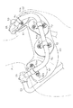
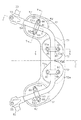
図1及び図2に示すように、マーチングキャリア10は、演奏者Pの胴体の前面を覆うキャリア本体11と、演奏者Pの両肩に沿って前後に掛けられるフレーム51とを備えている。キャリア本体11の下部には、マーチングドラム等の打楽器Dを支持する支持部材としての一対のロッド12が取着されている。各ロッド12の下端部には、打楽器Dを取り付けるためのフック12aが設けられている。打楽器Dの側面には、各ロッド12のフック12aが固定される固定部(図示せず)が備えられている。
Hereinafter, an embodiment embodying the present invention will be described with reference to FIGS.
As shown in FIGS. 1 and 2, the marching
図2及び図3に示すように、キャリア本体11は、上プレート40、下プレート20、及び下プレート20の裏面に取着されたクッション部材22を備えている。下プレート20は、金属や樹脂等の剛性を有する板材によって形成されている。下プレート20は、演奏者Pの腹に対向する略楕円状の腹部23と、腹部23から上方に突出する連結部24とを有している。腹部23は、演奏者Pの腹の形状に合わせて湾曲するように形成されている。
As shown in FIGS. 2 and 3, the
腹部23の前面には、一対のロッド12を保持する一対のロッドホルダ26が取着されている。各ロッドホルダ26は、下プレート20の裏面から複数の固定孔23aにそれぞれ挿入された複数の螺子25によって固定されている。各ロッドホルダ26の中央には、ロッド12の上端部が挿入される縦孔26aが設けられている。各ロッド12は、ロッドホルダ26の前方から挿入されたボルト27をナット29に締め付けることで、押え部材28を介してロッドホルダ26に保持される。一対のロッド12は、ロッドホルダ26に保持された状態で、下プレート20の腹部23の両側部に固定されている。クッション部材22は、演奏者Pの腹と接する部分である。クッション部材22は、スポンジやポリウレタン等の材料からなり、略楕円形状を有している。
A pair of
下プレート20は、連結部24において、4本のボルト31、ワッシャプレート32及びナットプレート33によって、上プレート40の下部に連結されている。下プレート20の連結部24と上プレート40との間には、四角板状のスペーサ34が介装されている。ワッシャプレート32及びスペーサ34には、各ボルト31が挿通される挿通孔32a、34aがそれぞれ設けられている。また、ナットプレート33には、各ボルト31の先端と螺合する螺旋孔33aが設けられている。
The
上プレート40は、下プレート20と同じく、金属板や樹脂等の剛性を有する板材によって形成されている。上プレート40には、下端から中央にかけて延びる一対の溝40aが設けられている。上プレート40の前方から4本のボルト31がワッシャプレート32の挿通孔32a、上プレート40の溝40a、スペーサ34及び連結部24の各挿通孔34a、24aの順に挿通されてナットプレート33の螺旋孔33aに締め付けられる。これにより、下プレート20は、上プレート40に対して移動不能に連結される。一方、各ボルト31を緩めることで、上プレート40の両溝40a内でボルト31が移動可能になる。これにより、下プレート20は、上プレート40に対し高さ方向に沿って移動可能になり、上プレート40に対する下プレート20の高さを調節することができる。
Similar to the
フレーム51は、上プレート40に連結される一対の前フレーム53と、両前フレーム53の後端を繋ぐ後フレーム54とからなる。各前フレーム53は、金属棒によってU字状に形成され、前端と後端とにおいて内方に向けてそれぞれ曲げられている。後フレーム54も、金属棒によってU字状に形成され、両端部において前方に向けてそれぞれ曲げられている。各前フレーム53は、前端部において、フレームホルダ41を介して、上プレート40に対し回動可能に連結されている。また、各前フレーム53は、後端部において、ヒンジ55を介して、後フレーム54に対し回動可能に連結されている。つまり、後フレーム54は、その両端部において、一対のヒンジ55を介して、両前フレーム53に対し回動可能に連結されている。本実施形態において、フレーム51は、演奏者Pの両肩に掛けられる略環状の肩掛け部として構成されている。
The
フレーム51を保持する一対のフレームホルダ41は、上プレート40の後方から挿入された複数の螺子42によって、上プレート40に対しそれぞれ固定されている。図6に示すように、各フレームホルダ41は、フレーム51の前端が挿入される第1横孔41aと、第1横孔41aから下方に開口したスリット41bと、ボルト43が挿入される第2横孔41cとを有している。また、フレームホルダ41の裏側には凹部が設けられ、この凹部に、ボルト43と螺合するナット44が収納されている。フレームホルダ41の前方から挿入されたボルト43をナット44に締め付けることで、フレームホルダ41の第1横孔41aの径が小さくなり、フレーム51の前端がフレームホルダ41に締め付けられる。これにより、フレーム51が上プレート40に対し回動不能に連結され、キャリア本体11に対するフレーム51の角度が固定される。一方、各ボルト43を緩めることで、フレームホルダ41による締め付けが解除され、フレーム51が上プレート40に対し回動可能になり、キャリア本体11に対するフレーム51の角度を調節することができる。本実施形態において、フレーム51は、演奏者Pの両肩に掛けられる略環状の肩掛け部として構成されている。
The pair of
図7に示すように、各ヒンジ55は、前フレーム53の後端が挿入される第1横孔55aと、後フレーム54の前端が挿入される第2横孔55bと、第1横孔55aから前方に開口されるスリット55cと、ボルト56が挿入される第1縦孔55dと、スプリングピン57が挿入される第2縦孔55eとを有している。後フレーム54は、ヒンジ55の上方から挿入されたスプリングピン57によって第2横孔55bに固定されている。ヒンジ55の裏側には凹部が設けられ、この凹部に、ボルト56と螺合するナット58が収納されている。ヒンジ55の上方から挿入されたボルト56をナット58に締め付けることで、ヒンジ55の横孔55aの径が小さくなり、各前フレーム53が対応するヒンジ55に締め付けられる。これにより、後フレーム54が前フレーム53に対し回動不能に連結され、前フレーム53に対する後フレーム54の角度が固定される。一方、各ボルト56を緩めることで、各ヒンジ55による締め付けが解除され、後フレーム54が前フレーム53に対し回動可能になり、前フレーム53に対する後フレーム54の角度を調節することができる。
As shown in FIG. 7, each hinge 55 includes a first
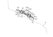
図4及び図5に示すように、前記後フレーム54は、各ヒンジ55から斜め後方に延びる一対の第1フレーム部54aと、両第1フレーム部54aを繋ぐ第2フレーム部54bとを有している。後フレーム54の各第1フレーム部54aには、略楕円状の肩プレート62が、クランプ60によってそれぞれ取着されている。肩プレート62は、金属や樹脂等の剛性を有する板材からなり、演奏者Pの肩の形状に合わせて湾曲されている。肩プレート62は、第1フレーム部54aを挟む両側に一対の長孔62aを有している。両長孔62aは、第1フレーム部54aの中心と直交する方向に延びている。
As shown in FIGS. 4 and 5, the
図7及び図8に示すように、各クランプ60は、後フレーム54を保持する断面U字状の保持部60aと、保持部60aから外方にそれぞれ延びる一対の固定片60bとを含む。固定片60bの中央には、ボルト80が挿通される挿通孔60cが設けられている。各肩プレート62の裏側には、肩クッション61が、クッションベース69を介して配置されている。各肩クッション61は、ポリウレタンやスポンジ等の弾性材料により形成されている。クッションベース69は、ゴム等の可撓性を有する材料からなり、後フレーム54の軸線に沿って略U字状に延びている。クッションベース69は、肩プレート62及び背中プレート72の位置の自由度を有しつつ、両プレート62,72の位置を決めるためのものである。各肩クッション61は、クッションベース69の両端部の裏面にそれぞれ接着されると共に、肩プレート62により演奏者Pの肩に対し当てがわれるように設けられている。また、肩クッション61及びクッションベース69において、各肩プレート62の各長孔62aと対応する位置に、挿通孔61a、69aがそれぞれ設けられている。
As shown in FIGS. 7 and 8, each
肩プレート62の上方からクランプ60の固定片60bを介して挿入されたボルト80を肩クッション61の挿通孔61a内のナット81に締め付けることで、肩プレート62、肩クッション61及びクッションベース69が一体化されると共に、後フレーム54の第1フレーム部54aに対する肩クッション61の角度が固定される。一方、各ボルト80を緩めることで、各肩プレート62が、後フレーム54の第1フレーム部54aに対して回動可能になる。この場合、肩クッション61も第1フレーム部54aに対して回動可能になるため、演奏者Pの肩の傾斜に合わせて、第1フレーム部54aに対する肩クッション61の角度が調節される。つまり、肩プレート62の角度を変えることで、肩プレート62と一体になって肩クッション61の角度が調節される。
The
また、この状態では、肩プレート62の長孔62a内でボルト80が移動可能になり、肩プレート62が第1フレーム部54aに対し横方向、即ち、図8に示す演奏者Pの首から腕に向かう肩の傾斜方向に沿って移動可能になる。この場合、肩プレート62と共に肩クッション61も移動可能になるため、演奏者Pの肩幅に合わせて、第1フレーム部54aに対する肩クッション61の横方向の取付位置が調節される。更に、この状態では、肩プレート62が第1フレーム部54aに沿って移動可能になる。この場合も、肩プレート62と共に肩クッション61も移動可能になるため、演奏者Pの肩の位置に合わせて、第1フレーム部54aに対する肩プレート62の前後方向の取付位置も調節される。
Further, in this state, the
図4及び図5に示すように、後フレーム54の第2フレーム部54bには、一対の背中プレート72がクランプ60によって取着されている。背中プレート72は、肩プレート62と同じく、金属や樹脂等の剛性を有する板材からなり、演奏者Pの背中の形状に合わせて湾曲されている。背中プレート72は、第2フレーム部54bを挟む両側に一対の挿通孔72aを有している。各背中プレート72は、演奏者Pの身体の中心線Oに対し対称に、かつ、隣接する背中プレート72との間に所定の距離を置いて配置されている。両背中プレート72の裏側には、背中クッション71がクッションベース69を介して配置されている。背中クッション71は、肩クッション61と同じく、ポリウレタンやスポンジ等の弾性材料からなり、肩クッション61よりも横長な略楕円形状を有している。背中クッション71は、クッションベース69の中央部の裏面に接着されると共に、両背中プレート72により演奏者Pの背中に対し当てがわれるように設けられている。
As shown in FIGS. 4 and 5, a pair of
図9に示すように、背中クッション71及びクッションベース69においても、背中プレート72の挿通孔72aと対応する位置に、挿通孔71a、69aがそれぞれ設けられている。背中プレート72の後方からクランプ60の固定片60bを介して挿入されたボルト82を背中クッション71の挿通孔71a内のナット83に締め付けることで、背中プレート72、背中クッション71及びクッションベース69が一体化されると共に、後フレーム54の第2フレーム部54bに対する背中クッション71の角度が固定される。一方、各ボルト82を緩めることで、各背中プレート72が、後フレーム54の第2フレーム部54bに対して回動可能になる。この場合、背中クッション71も第2フレーム部54bに対して回動可能になるため、演奏者Pの首から臀部に向かう背中の傾斜に合わせて、第2フレーム部54bに対する背中クッション71の角度も調節される。つまり、背中プレート72の角度を変えることで、背中プレート72と一体になって背中クッション71の角度が調節される。
As shown in FIG. 9, also in the
本実施形態によれば、以下のような効果を得ることができる。
(1)各肩クッション61は、後フレーム54の第1フレーム部54aに対して回動可能に取着され、背中クッション71は、後フレーム54の第2フレーム部54bに対して回動可能に取着されている。この場合、演奏者Pの肩や背中の形状に合わせて、フレーム51に対する肩クッション61の角度と背中クッション71の角度とを別々に調節することができる。これにより、演奏者Pの身体と肩クッション61及び背中クッション71との接触面積を十分に確保することができる。よって、演奏者Pがその前方で打楽器Dを支持する場合、演奏者Pの肩や背中における特定の箇所に打楽器Dの荷重が集中することを抑止でき、演奏者Pへの負担を軽減することができる。
According to this embodiment, the following effects can be obtained.
(1) Each
(2)肩クッション61は、後フレーム54の第1フレーム部54aに対して移動可能に取着されている。この場合、演奏者Pの肩の位置に合わせて、フレーム51に対する肩クッション61の前後方向の取付位置を調節することができる。これにより、演奏者Pの肩と肩クッション61との接触面積を十分に確保することが容易になる。
(2) The
(3)フレーム51は、一対の前フレーム53と後フレーム54とからなり、後フレーム54は、両前フレーム53に対し回動可能に連結されている。この場合、演奏者Pの体型に合わせて、前フレーム53に対する後フレーム54の角度を調節することで、フレーム51の前方への出っ張りを更に小さく抑えることができる。これにより、演奏者Pがマーチングキャリア10を装着して、更にその上から衣服を着用したときの見栄えをより一層向上させることができる。
(3) The
(4)肩プレート62は、後フレーム54の第1フレーム部54aに対し横方向に沿って移動可能に取着されている。この場合、演奏者Pの肩幅の大きさに合わせて、フレーム51に対する肩クッション61の横方向の取付位置を調節することができる。これにより、演奏者Pの肩と肩クッション61との接触面積を確保することが一層容易になる。
(4) The
(5)下プレート20は、上プレート40に対し高さ方向に沿って移動可能に連結されている。この場合、演奏者Pの肩に対する腹の位置に合わせて、下プレート20の高さを調節することができる。これにより、演奏者Pの腹や肩や背中といった特定の部位に打楽器Dの荷重が集中することを抑止でき、演奏者Pへの負担をより一層軽減することができる。
(5) The
(6)フレーム51は、キャリア本体11の上プレート40に対し回動可能に連結されている。この場合、演奏者Pの体型に合わせて、キャリア本体11に対するフレーム51の角度を調節することで、マーチングキャリア10の前後方向の幅を調節することができる。これにより、演奏者Pの胴体とマーチングキャリア10との間の隙間を極力小さく抑えることができ、演奏者Pに対するマーチングキャリア10のフィット感を向上させることができる。
(6) The
(7)肩クッション61は、フレーム51に対して回動可能に取着された肩プレート62の裏側に配置され、フレーム51に対する肩プレート62の角度を変えることで肩クッション61の角度が調節される。この場合、肩プレート62によって、肩クッション61の角度を容易に調節できると共に、肩クッション61の角度を確実に維持することもできる。
(7) The
(8)背中クッション71は、フレーム51に対して回動可能に取着された背中プレート72の裏側に配置され、フレーム51に対する背中プレート72の角度を変えることで背中クッション71の角度が調節される。この場合、背中プレート72によって、背中クッション71の角度を容易に調節することができると共に、背中クッション71の角度を確実に維持することもできる。
(8) The
(9)各背中プレート72は、演奏者Pの胴体の中心線Oに対し対称となるように配置されている。この場合、演奏者Pの背骨の位置を避けて各背中プレート72の位置が設定されるため、演奏者Pへの負担を軽減できると共に、マーチングキャリア10を装着したときの違和感を軽減することもできる。
(9) The
なお、上記実施形態は以下のように変更してもよい。
・本実施形態において、前フレーム53と後フレーム54との連結構造を以下のように変更してもよい。例えば、後フレーム54を前フレーム53に対して移動可能に取着し、前フレーム53に対する後フレーム54の前後方向の連結位置を調節できるようにしてもよい。この場合、演奏者Pの体型に合わせて、前フレーム53に対する後フレーム54の前後方向の連結位置を調節することで、フレーム51の前方への出っ張りを小さく抑えることができる。これにより、演奏者Pがマーチングキャリア10を装着して、更にその上から衣服を着用したときの見栄えを更に向上させることができる。また、演奏者Pの胴体とマーチングキャリア10との間の隙間を更に極力抑えることもでき、演奏者Pに対するマーチングキャリア10のフィット感を一層向上させることもできる。
In addition, you may change the said embodiment as follows.
-In this embodiment, you may change the connection structure of the
・本実施形態において、また、肩クッション61及び肩プレート62は、各ボルト80を締め付けることで後フレーム54の第2フレーム部54aに対し固定されていたが、後フレーム54の第2フレーム部54aに対し常に回動可能に取着されていてもよい。同様に、背中クッション71及び背中プレート72についても、各ボルト82を締め付けることで後フレーム54の第2フレーム部54bに対し固定されていたが、後フレーム54の第2フレーム部54bに対し常に回動可能に取着されていてもよい。この場合、演奏者Pがマーチングキャリア10を着脱する際、背中プレート72は、クッションベース69によって、裏返らないように支持されている。
In the present embodiment, the
・本実施形態において、背中クッション71の数を2つ以上に変更してもよい。また、背中クッション71の数に応じて、又は背中クッション71の数に関係なく、背中プレート72の数を変更してもよい。
In the present embodiment, the number of back cushions 71 may be changed to two or more. Further, the number of
・本実施形態において、後フレーム54は、前フレーム53と一体化されていてもよい。
・本実施形態において、下プレート20は、上プレート40と一体化されていてもよい。
In the present embodiment, the
In the present embodiment, the
・本実施形態において、フレーム51は、キャリア本体11と一体化されていてもよい。
・本実施形態において、マーチングキャリア10を、打楽器D以外の楽器を支持するものに適用してもよい。また、マーチングキャリア10に装着される楽器の種類及び個数に応じて、支持部材としてのロッド12を形状や個数などを適宜変更してもよい。
In the present embodiment, the
-In this embodiment, you may apply the
O…中心線、D…楽器、P…演奏者、10…マーチングキャリア、11…キャリア本体、12…ロッド(支持部材)、20…下プレート、40…上プレート、51…フレーム、53…前フレーム、54…後フレーム、61…肩クッション、62…肩プレート、71…背中クッション、72…背中プレート。
O ... center line, D ... musical instrument, P ... performer, 10 ... marching carrier, 11 ... carrier body, 12 ... rod (support member), 20 ... lower plate, 40 ... upper plate, 51 ... frame, 53 ...
Claims (10)
前記演奏者の胴体の前面に当接されるキャリア本体と、
前記キャリア本体の下部に装着され、前記楽器を支持する支持部材と、
前記キャリア本体の上部に設けられ、前記演奏者の両肩に沿ってその前後に配置されるフレームと、
前記フレームに対し回動可能に取着され、前記演奏者の両肩に当接される一対の肩クッションと、
前記フレームに対し回動可能に取着され、前記演奏者の背中に当接される背中クッションとを備え、
前記フレームに対する前記肩クッション及び前記背中クッションの角度が別々に調節可能であることを特徴とするマーチングキャリア。 A marching carrier that supports the instrument in front of the performer,
A carrier body abutting against the front of the performer's torso;
A support member attached to a lower portion of the carrier body and supporting the musical instrument;
A frame provided at the top of the carrier body and disposed in front and back along the shoulders of the performer;
A pair of shoulder cushions pivotably attached to the frame and abutted against both shoulders of the performer;
A back cushion that is pivotally attached to the frame and is in contact with the back of the performer;
A marching carrier characterized in that angles of the shoulder cushion and the back cushion with respect to the frame can be adjusted separately.
前記肩クッションは、前記フレームに対し移動可能に取着され、
前記フレームに対する前記肩クッションの前後方向の取付位置が調節可能であることを特徴とするマーチングキャリア。 The marching carrier according to claim 1,
The shoulder cushion is movably attached to the frame;
A marching carrier characterized in that the mounting position of the shoulder cushion in the front-rear direction with respect to the frame is adjustable.
前記フレームは、前記キャリア本体に連結される一対の前フレームと、前記両前フレームの後端に連結される一つの後フレームとからなり、前記後フレームは、前記前フレームに対するその位置を調節可能に取着されていることを特徴とするマーチングキャリア。 The marching carrier according to claim 1,
The frame includes a pair of front frames connected to the carrier body and one rear frame connected to the rear ends of the two front frames, and the position of the rear frame relative to the front frame is adjustable. A marching carrier characterized by being attached to.
前記後フレームは、前記前フレームに対し回動可能に連結され、
前記前フレームに対する前記後フレームの角度が調節可能であることを特徴とするマーチングキャリア。 The marching carrier according to claim 3,
The rear frame is rotatably connected to the front frame,
A marching carrier characterized in that an angle of the rear frame with respect to the front frame is adjustable.
前記肩クッションは、前記フレームに対し横方向に沿って移動可能に取着され、前記フレームに対する前記肩クッションの横方向の取付位置が調節可能であることを特徴とするマーチングキャリア。 The marching carrier according to claim 1,
The marching carrier, wherein the shoulder cushion is attached to the frame so as to be movable in a lateral direction, and a lateral mounting position of the shoulder cushion with respect to the frame is adjustable.
前記キャリア本体は、前記演奏者の胸に対向する上プレートと、前記支持部材を有すると共に前記演奏者の腹に対向する下プレートとからなり、前記下プレートは、前記上プレートに対し高さ方向に沿って移動可能に連結され、前記上プレートに対する前記下プレートの高さが調節可能であることを特徴とするマーチングキャリア。 The marching carrier according to claim 1,
The carrier body includes an upper plate facing the performer's chest and a lower plate having the support member and facing the performer's belly, the lower plate being in a height direction with respect to the upper plate. A marching carrier characterized in that the height of the lower plate relative to the upper plate is adjustable.
前記フレームは、前記キャリア本体に対し回動可能に連結され、
前記キャリア本体に対する前記フレームの角度が調節可能であることを特徴とするマーチングキャリア。 The marching carrier according to claim 1,
The frame is rotatably connected to the carrier body,
A marching carrier characterized in that an angle of the frame with respect to the carrier body is adjustable.
前記各肩クッションは、前記フレームに対し回動可能に取着された肩プレートの裏側に配置され、前記フレームに対する前記肩プレートの角度を変えることで前記肩クッションの角度が調節されることを特徴とするマーチングキャリア。 The marching carrier according to claim 1,
Each of the shoulder cushions is disposed on the back side of a shoulder plate that is rotatably attached to the frame, and the angle of the shoulder cushion is adjusted by changing the angle of the shoulder plate with respect to the frame. A marching career.
前記背中クッションは、前記フレームに対し回動可能に取着された一対の背中プレートの裏側に配置され、前記フレームに対する前記背中プレートの角度を変えることで前記背中クッションの角度が調節されることを特徴とするマーチングキャリア。 The marching carrier according to claim 1,
The back cushion is disposed on the back side of a pair of back plates that are rotatably attached to the frame, and the angle of the back cushion is adjusted by changing the angle of the back plate with respect to the frame. A characteristic marching carrier.
前記一対の背中プレートは、前記演奏者の胴体の中心線に対し対称となるように配置されていることを特徴とするマーチングキャリア。 The marching carrier according to claim 9,
The pair of back plates are arranged so as to be symmetrical with respect to the center line of the performer's torso.
Priority Applications (2)
| Application Number | Priority Date | Filing Date | Title |
|---|---|---|---|
| JP2007119679A JP4313402B2 (en) | 2007-04-27 | 2007-04-27 | Marching career |
| US11/841,494 US7554024B2 (en) | 2007-04-27 | 2007-08-20 | Marching carrier |
Applications Claiming Priority (1)
| Application Number | Priority Date | Filing Date | Title |
|---|---|---|---|
| JP2007119679A JP4313402B2 (en) | 2007-04-27 | 2007-04-27 | Marching career |
Publications (2)
| Publication Number | Publication Date |
|---|---|
| JP2008275907A JP2008275907A (en) | 2008-11-13 |
| JP4313402B2 true JP4313402B2 (en) | 2009-08-12 |
Family
ID=39885452
Family Applications (1)
| Application Number | Title | Priority Date | Filing Date |
|---|---|---|---|
| JP2007119679A Active JP4313402B2 (en) | 2007-04-27 | 2007-04-27 | Marching career |
Country Status (2)
| Country | Link |
|---|---|
| US (1) | US7554024B2 (en) |
| JP (1) | JP4313402B2 (en) |
Families Citing this family (18)
| Publication number | Priority date | Publication date | Assignee | Title |
|---|---|---|---|---|
| US8053655B2 (en) * | 2000-02-03 | 2011-11-08 | Randall L May | Carrier assembly for percussion instruments |
| US9754568B2 (en) * | 2004-12-23 | 2017-09-05 | Randall May International Incorporated | Instrument carrier with articulating back brace |
| US8646666B2 (en) * | 2004-12-23 | 2014-02-11 | Randall May International, Incorporated | Carrier with adjustable parallel track structure for retaining musical instruments |
| JP4313402B2 (en) * | 2007-04-27 | 2009-08-12 | 星野楽器製造 株式会社 | Marching career |
| US7671261B1 (en) * | 2008-12-24 | 2010-03-02 | Pearl Musical Instruments Co. | Musical instrument carrier and related methods |
| US8026433B2 (en) * | 2010-01-07 | 2011-09-27 | Ned Allen Place | Apparatus for using a person's hips to carry the load of marching percussion equipment or other objects which are carried near waist-height and in front of a person |
| KR101416664B1 (en) * | 2012-09-25 | 2014-07-14 | 이상희 | facilitates easy mobility and light electric cello |
| USD780858S1 (en) * | 2013-03-14 | 2017-03-07 | Josh Pfaff | Weighted backpack |
| KR101537776B1 (en) * | 2013-05-07 | 2015-07-17 | 김동현 | Shoulder supporter for electric korean instruments |
| EP2886930B1 (en) * | 2013-12-23 | 2018-11-14 | Sacci Ryggsäckar AB | Carrying device |
| DE102014012402B4 (en) * | 2014-08-21 | 2016-12-22 | Markus Maier | One-armed carrying device |
| JP6728609B2 (en) * | 2015-09-25 | 2020-07-22 | ヤマハ株式会社 | Musical instrument carrier |
| DE102016009753A1 (en) * | 2016-08-10 | 2018-02-15 | Andreas Stihl Ag & Co. Kg | Back carrier and extension plate for a backpack |
| JP1591620S (en) * | 2016-12-16 | 2017-11-27 | ||
| JP6624606B1 (en) * | 2018-11-05 | 2019-12-25 | 志保 金山 | Strap pad for wind instruments |
| KR102240401B1 (en) * | 2019-12-18 | 2021-04-15 | 김미란 | Saxophone strap |
| US11284699B2 (en) * | 2020-02-10 | 2022-03-29 | Rolland Fontaine | Body-worn aid for decedent removal and other load-moving applications |
| JP7417280B2 (en) * | 2021-05-20 | 2024-01-18 | 星野楽器株式会社 | marching carrier |
Family Cites Families (20)
| Publication number | Priority date | Publication date | Assignee | Title |
|---|---|---|---|---|
| US1191425A (en) * | 1915-08-13 | 1916-07-18 | Henry Koch | Adjustable table. |
| US3332593A (en) * | 1966-05-31 | 1967-07-25 | Elmer E Fauser | Camera support |
| US4139132A (en) * | 1977-03-31 | 1979-02-13 | Martha S. Fairchild, trustee | Backpack levers |
| US4236712A (en) * | 1979-01-31 | 1980-12-02 | Lambert Jr Lloyd J | Standing calf exercise machine |
| US4402441A (en) * | 1981-01-09 | 1983-09-06 | Jones Russell S | Musical instrument carrier |
| US4453442A (en) * | 1982-06-04 | 1984-06-12 | Laflame Thomas R | Carrier for a percussion instrument |
| US4865314A (en) * | 1985-05-22 | 1989-09-12 | Carter Jr Stanley R | Frame for barbell weights or similar article |
| US4799610A (en) * | 1988-03-14 | 1989-01-24 | Hsieh Wu H | Carrying holder |
| US5108095A (en) * | 1990-12-07 | 1992-04-28 | Southern Xercise, Inc. | Squat exercise apparatus |
| US5573158A (en) * | 1993-10-04 | 1996-11-12 | Penn; Henry A. | Spinning drum carrier |
| US7394008B2 (en) * | 1996-01-18 | 2008-07-01 | Randall L May | Carrier assembly for percussion instruments |
| US6323407B1 (en) * | 1996-01-18 | 2001-11-27 | Randall L. May | Carrier assembly for percussion instruments |
| US6881886B2 (en) * | 1996-01-18 | 2005-04-19 | Randall L May | Carrier assembly for percussion instruments |
| US6329583B1 (en) * | 1996-01-18 | 2001-12-11 | Randall L. May | Carrier assembly for percussion instruments |
| USD513289S1 (en) * | 2004-01-23 | 2005-12-27 | Rodolfo Panatta | Body-building machine |
| US7166790B2 (en) * | 2004-11-06 | 2007-01-23 | Randall L May | Percussion instrument carrier assembly |
| US7326842B2 (en) * | 2004-12-23 | 2008-02-05 | Randall L May | Mono postal percussion instrument carrier |
| US7810684B2 (en) * | 2005-02-24 | 2010-10-12 | Randall L May | Percussion instrument carrier with expandable shoulder supports |
| US20080217368A1 (en) * | 2007-03-08 | 2008-09-11 | Melvin John Denton | Hands-free load carrying apparatus |
| JP4313402B2 (en) * | 2007-04-27 | 2009-08-12 | 星野楽器製造 株式会社 | Marching career |
-
2007
- 2007-04-27 JP JP2007119679A patent/JP4313402B2/en active Active
- 2007-08-20 US US11/841,494 patent/US7554024B2/en active Active
Also Published As
| Publication number | Publication date |
|---|---|
| US7554024B2 (en) | 2009-06-30 |
| US20080264236A1 (en) | 2008-10-30 |
| JP2008275907A (en) | 2008-11-13 |
Similar Documents
| Publication | Publication Date | Title |
|---|---|---|
| JP4313402B2 (en) | Marching career | |
| US4047757A (en) | Seating structures with flexible backs | |
| US4015759A (en) | Backpack frame having shoulder and hip supports with flexible connection to hip support | |
| CN101263046B (en) | Customizable saddle structure, particularly for bicycles, having a removable seat element | |
| US20120086246A1 (en) | Twin-pad bicycle seat for long distance cycling | |
| JPH06171566A (en) | Seat and saddle for use on bicycle or exerciser | |
| US5597202A (en) | Slung fabric bicycle seat | |
| KR20170039670A (en) | Movement assistance device | |
| US20060270480A1 (en) | Infant swing apparatus | |
| CA2209755C (en) | Adjustable saddle | |
| US5772091A (en) | Support apparatus for a musical instrument | |
| JP2016142952A (en) | Musical instrument carrier | |
| US6588789B1 (en) | Adjustable support for sports motorcycle | |
| CN109720256A (en) | The neck brace of headrest for vehicles | |
| JP4160405B2 (en) | Bicycle seat | |
| US20040113470A1 (en) | Prostate protecting bicycle seat | |
| CN100584685C (en) | Support structure, in particular for bicycles and human body support frames | |
| US6528712B2 (en) | Upper pivot support for a guitar | |
| US20090096266A1 (en) | Seat frame assembly | |
| JP2021534031A (en) | Adjustable lumbar support for vehicle seats | |
| JP2008539126A5 (en) | ||
| JP4325302B2 (en) | Detachable wheelchair backrest or seat and belt | |
| JP7377514B2 (en) | A back support with a body support mechanism and a wheelchair using it | |
| JP2003005745A (en) | Shoulder hanging type percussion instrument holder | |
| JP4197045B2 (en) | Chair |
Legal Events
| Date | Code | Title | Description |
|---|---|---|---|
| A621 | Written request for application examination |
Free format text: JAPANESE INTERMEDIATE CODE: A621 Effective date: 20081128 |
|
| A977 | Report on retrieval |
Free format text: JAPANESE INTERMEDIATE CODE: A971007 Effective date: 20090410 |
|
| TRDD | Decision of grant or rejection written | ||
| A01 | Written decision to grant a patent or to grant a registration (utility model) |
Free format text: JAPANESE INTERMEDIATE CODE: A01 Effective date: 20090428 |
|
| A01 | Written decision to grant a patent or to grant a registration (utility model) |
Free format text: JAPANESE INTERMEDIATE CODE: A01 |
|
| A61 | First payment of annual fees (during grant procedure) |
Free format text: JAPANESE INTERMEDIATE CODE: A61 Effective date: 20090514 |
|
| FPAY | Renewal fee payment (event date is renewal date of database) |
Free format text: PAYMENT UNTIL: 20120522 Year of fee payment: 3 |
|
| R150 | Certificate of patent or registration of utility model |
Ref document number: 4313402 Country of ref document: JP Free format text: JAPANESE INTERMEDIATE CODE: R150 Free format text: JAPANESE INTERMEDIATE CODE: R150 |
|
| S111 | Request for change of ownership or part of ownership |
Free format text: JAPANESE INTERMEDIATE CODE: R313111 |
|
| FPAY | Renewal fee payment (event date is renewal date of database) |
Free format text: PAYMENT UNTIL: 20120522 Year of fee payment: 3 |
|
| FPAY | Renewal fee payment (event date is renewal date of database) |
Free format text: PAYMENT UNTIL: 20120522 Year of fee payment: 3 |
|
| R360 | Written notification for declining of transfer of rights |
Free format text: JAPANESE INTERMEDIATE CODE: R360 |
|
| FPAY | Renewal fee payment (event date is renewal date of database) |
Free format text: PAYMENT UNTIL: 20120522 Year of fee payment: 3 |
|
| R360 | Written notification for declining of transfer of rights |
Free format text: JAPANESE INTERMEDIATE CODE: R360 |
|
| R371 | Transfer withdrawn |
Free format text: JAPANESE INTERMEDIATE CODE: R371 |
|
| S111 | Request for change of ownership or part of ownership |
Free format text: JAPANESE INTERMEDIATE CODE: R313111 |
|
| FPAY | Renewal fee payment (event date is renewal date of database) |
Free format text: PAYMENT UNTIL: 20120522 Year of fee payment: 3 |
|
| R350 | Written notification of registration of transfer |
Free format text: JAPANESE INTERMEDIATE CODE: R350 |
|
| FPAY | Renewal fee payment (event date is renewal date of database) |
Free format text: PAYMENT UNTIL: 20150522 Year of fee payment: 6 |
|
| R250 | Receipt of annual fees |
Free format text: JAPANESE INTERMEDIATE CODE: R250 |
|
| R250 | Receipt of annual fees |
Free format text: JAPANESE INTERMEDIATE CODE: R250 |
|
| R250 | Receipt of annual fees |
Free format text: JAPANESE INTERMEDIATE CODE: R250 |
|
| R250 | Receipt of annual fees |
Free format text: JAPANESE INTERMEDIATE CODE: R250 |
|
| R250 | Receipt of annual fees |
Free format text: JAPANESE INTERMEDIATE CODE: R250 |