JP4311643B2 - Method for manufacturing permanent magnet type rotating electric machine and method for manufacturing permanent magnet type synchronous generator for wind power generation - Google Patents
Method for manufacturing permanent magnet type rotating electric machine and method for manufacturing permanent magnet type synchronous generator for wind power generation Download PDFInfo
- Publication number
- JP4311643B2 JP4311643B2 JP2003555654A JP2003555654A JP4311643B2 JP 4311643 B2 JP4311643 B2 JP 4311643B2 JP 2003555654 A JP2003555654 A JP 2003555654A JP 2003555654 A JP2003555654 A JP 2003555654A JP 4311643 B2 JP4311643 B2 JP 4311643B2
- Authority
- JP
- Japan
- Prior art keywords
- rotor
- permanent magnet
- magnet type
- stator
- type rotating
- Prior art date
- Legal status (The legal status is an assumption and is not a legal conclusion. Google has not performed a legal analysis and makes no representation as to the accuracy of the status listed.)
- Expired - Fee Related
Links
Images


Classifications
-
- H—ELECTRICITY
- H02—GENERATION; CONVERSION OR DISTRIBUTION OF ELECTRIC POWER
- H02K—DYNAMO-ELECTRIC MACHINES
- H02K21/00—Synchronous motors having permanent magnets; Synchronous generators having permanent magnets
- H02K21/12—Synchronous motors having permanent magnets; Synchronous generators having permanent magnets with stationary armatures and rotating magnets
- H02K21/14—Synchronous motors having permanent magnets; Synchronous generators having permanent magnets with stationary armatures and rotating magnets with magnets rotating within the armatures
-
- F—MECHANICAL ENGINEERING; LIGHTING; HEATING; WEAPONS; BLASTING
- F03—MACHINES OR ENGINES FOR LIQUIDS; WIND, SPRING, OR WEIGHT MOTORS; PRODUCING MECHANICAL POWER OR A REACTIVE PROPULSIVE THRUST, NOT OTHERWISE PROVIDED FOR
- F03D—WIND MOTORS
- F03D9/00—Adaptations of wind motors for special use; Combinations of wind motors with apparatus driven thereby; Wind motors specially adapted for installation in particular locations
- F03D9/20—Wind motors characterised by the driven apparatus
- F03D9/25—Wind motors characterised by the driven apparatus the apparatus being an electrical generator
-
- H—ELECTRICITY
- H02—GENERATION; CONVERSION OR DISTRIBUTION OF ELECTRIC POWER
- H02K—DYNAMO-ELECTRIC MACHINES
- H02K21/00—Synchronous motors having permanent magnets; Synchronous generators having permanent magnets
- H02K21/12—Synchronous motors having permanent magnets; Synchronous generators having permanent magnets with stationary armatures and rotating magnets
- H02K21/14—Synchronous motors having permanent magnets; Synchronous generators having permanent magnets with stationary armatures and rotating magnets with magnets rotating within the armatures
- H02K21/16—Synchronous motors having permanent magnets; Synchronous generators having permanent magnets with stationary armatures and rotating magnets with magnets rotating within the armatures having annular armature cores with salient poles
-
- F—MECHANICAL ENGINEERING; LIGHTING; HEATING; WEAPONS; BLASTING
- F05—INDEXING SCHEMES RELATING TO ENGINES OR PUMPS IN VARIOUS SUBCLASSES OF CLASSES F01-F04
- F05B—INDEXING SCHEME RELATING TO WIND, SPRING, WEIGHT, INERTIA OR LIKE MOTORS, TO MACHINES OR ENGINES FOR LIQUIDS COVERED BY SUBCLASSES F03B, F03D AND F03G
- F05B2220/00—Application
- F05B2220/70—Application in combination with
- F05B2220/706—Application in combination with an electrical generator
- F05B2220/7068—Application in combination with an electrical generator equipped with permanent magnets
-
- F—MECHANICAL ENGINEERING; LIGHTING; HEATING; WEAPONS; BLASTING
- F05—INDEXING SCHEMES RELATING TO ENGINES OR PUMPS IN VARIOUS SUBCLASSES OF CLASSES F01-F04
- F05B—INDEXING SCHEME RELATING TO WIND, SPRING, WEIGHT, INERTIA OR LIKE MOTORS, TO MACHINES OR ENGINES FOR LIQUIDS COVERED BY SUBCLASSES F03B, F03D AND F03G
- F05B2240/00—Components
- F05B2240/40—Use of a multiplicity of similar components
-
- F—MECHANICAL ENGINEERING; LIGHTING; HEATING; WEAPONS; BLASTING
- F05—INDEXING SCHEMES RELATING TO ENGINES OR PUMPS IN VARIOUS SUBCLASSES OF CLASSES F01-F04
- F05B—INDEXING SCHEME RELATING TO WIND, SPRING, WEIGHT, INERTIA OR LIKE MOTORS, TO MACHINES OR ENGINES FOR LIQUIDS COVERED BY SUBCLASSES F03B, F03D AND F03G
- F05B2240/00—Components
- F05B2240/50—Bearings
- F05B2240/51—Bearings magnetic
- F05B2240/511—Bearings magnetic with permanent magnets
-
- H—ELECTRICITY
- H02—GENERATION; CONVERSION OR DISTRIBUTION OF ELECTRIC POWER
- H02K—DYNAMO-ELECTRIC MACHINES
- H02K7/00—Arrangements for handling mechanical energy structurally associated with dynamo-electric machines, e.g. structural association with mechanical driving motors or auxiliary dynamo-electric machines
- H02K7/18—Structural association of electric generators with mechanical driving motors, e.g. with turbines
- H02K7/1807—Rotary generators
- H02K7/1823—Rotary generators structurally associated with turbines or similar engines
- H02K7/183—Rotary generators structurally associated with turbines or similar engines wherein the turbine is a wind turbine
- H02K7/1838—Generators mounted in a nacelle or similar structure of a horizontal axis wind turbine
-
- Y—GENERAL TAGGING OF NEW TECHNOLOGICAL DEVELOPMENTS; GENERAL TAGGING OF CROSS-SECTIONAL TECHNOLOGIES SPANNING OVER SEVERAL SECTIONS OF THE IPC; TECHNICAL SUBJECTS COVERED BY FORMER USPC CROSS-REFERENCE ART COLLECTIONS [XRACs] AND DIGESTS
- Y02—TECHNOLOGIES OR APPLICATIONS FOR MITIGATION OR ADAPTATION AGAINST CLIMATE CHANGE
- Y02E—REDUCTION OF GREENHOUSE GAS [GHG] EMISSIONS, RELATED TO ENERGY GENERATION, TRANSMISSION OR DISTRIBUTION
- Y02E10/00—Energy generation through renewable energy sources
- Y02E10/70—Wind energy
- Y02E10/72—Wind turbines with rotation axis in wind direction
Abstract
Description
【0001】
【発明の属する技術分野】
この発明は、永久磁石型回転電機および風力発電用永久磁石型同期発電機に関し、特に、永久磁石による複数の磁極を有する回転子と電機子巻線を磁極に巻き回された固定子とを具備した永久磁石型回転電機および風力発電用永久磁石型同期発電機に関する。
【0002】
【従来の技術】
従来より、永久磁石による複数の磁極を有する回転子と電機子巻線を磁極に集中的に巻き回された固定子とを具備したいわゆる集中巻の永久磁石型回転電機が様々な用途に用いられている。集中巻は固定子の磁極に集中的に巻き回された構造であるがゆえに機械による自動巻きが可能であるため、サーボ用などの小型モータを中心に多く用いられている。このような小型モータでは銅損、鉄損、機械損が損失の中でほとんどを占めるため、回転子に発生する渦電流損は問題とならないことがほとんどである。
【0003】
一方、数kWを超える大型機においては、これまでは、分布巻が用いられることが多かったが、コイルエンドの小さい集中巻の必要性が大型機においても高まりつつある。例えば、風力発電、特に、ギヤレス型の風力発電システムに永久磁石型同期発電機を採用する場合、分布巻と比較して、集中巻は、コイルエンドが小さいため軸方向の長さを低減でき、さらに電機子巻線に発生する銅損が小さいため高効率化が実現できるという点で、集中巻を選択した方がよいと言える。
【0004】
上記のように集中巻はコイルエンドの小ささや、さらに、自動巻きが可能であるといった利点を持っている反面、電機子電流の起磁力に起因する回転子の渦電流損が分布巻に比べて大きくなるという問題を抱えている。さらに近年、希土類磁石のような残留磁束密度と保磁力が高い高性能磁石が大容量機の回転子の磁極として積極的に利用されるようになっているが、例えば、Nd−Fe−B系の磁石は導電率が高くフェライト系の磁石に比べて渦電流が流れやすいという特徴を持っている。
【0005】
以上のような理由から、集中巻の大容量機、特に、回転子の直径が1mを超えるような永久磁石型回転電機や風力発電用永久磁石型同期発電機では、回転子に発生する渦電流損が無視できないレベルに達することがあり、この渦電流損により回転機の効率が著しく下がったり、この渦電流損によって回転子の温度が上昇し、磁石の減磁を招くという課題があった。また、減磁には至らなくとも温度上昇によって残留磁束密度が低下し、その結果、磁石が発生する磁束が減少する。そのため、温度上昇のない状態と同じ出力を出すためには電機子電流を多く流す必要があり、銅損が増加し、効率が低下してしまうという課題もあった。
【0006】
このような課題を解決する手法として、従来から回転子のヨークを積層鋼鈑で構成することにより、渦電流を低減する手法があった。また、特開2001−54271号公報には、回転子の鉄心を積層鋼鈑とせず、塊状ヨークで構成し、かつそのヨークを区分し、渦電流の経路を絶つことにより、渦電流を低減する手法が開示されている。
【0007】
しかしながら、回転子のヨークを積層構造にすると、塊状ヨークで構成する場合に比べてコスト高になるという問題があり、また、上記特開2001−54271号公報のように塊状ヨークを区分すると以下のような様々な問題を生ずる。例えば、一体の塊状ヨークに比べて加工費が増えてコスト高になるという問題があり、さらに回転子のヨークに設けられた、絶縁部の厚さが各絶縁部においてバラツキが生じた場合に、モータの空隙部の磁束密度にもバラツキが生じ、結果的に電磁力の不均一につながり、騒音や振動につながるという懸念がある。また、ヨークを区分するために、電気的に絶縁分割するための絶縁部があるが故に、その部分で起磁力が消費されるため、回転電機の出力低下につながるという問題がある。
【0008】
【発明が解決しようとする課題】
上記のように、従来の永久磁石型回転電機や風力発電用永久磁石型同期発電機等においては、過電流を低減するために、回転子のヨークを積層構造にしたり、塊状ヨークを区分したりする構造が提案されてきたが、積層構造にすると加工費が増えてコスト高になるという問題点があり、また、塊状ヨークを区分すると、モータの空隙部の磁束密度にバラツキが生じ、結果的に電磁力の不均一につながってしまうという問題点があった。そのため、回転子のヨークは一体型であるのが望ましいと言える。
【0009】
本発明は、かかる問題点を解決するためになされたものであり、回転子ヨークを一体型にした構造を保ちつつ、回転子の渦電流損を低減することができる永久磁石型回転電機および風力発電用永久磁石型同期発電機を得ることを目的としている。
【0010】
【課題を解決するための手段】
この発明は、永久磁石による複数の磁極を有する回転子と電機子巻線がティースに集中的に巻き回された固定子とを有する永久磁石型回転電機の製造方法および風力発電用永久磁石型同期発電機の製造方法であって、上記回転子の磁極の極対数をP、上記回転子の直径をD[m]とし、上記固定子の電機子起磁力の所定の調波成分の空間次数をN(機械角360度を1次とする)とし、上記永久磁石型回転電機の出力をPout [kW]として、上記DをD=0.00045Pout+1.2以上となるように設定し、上記回転子に発生する渦電流損の割合を評価するパラメータX(単位はm)を
X=(N+P)1.5N-4P2D
と定義した場合に、上記Xの値が所定の値より小さくなるように、上記、P、D、Nの値を選択し、2P個の永久磁石を回転子に取り付ける永久磁石型回転電機の製造方法および風力発電用永久磁石型同期発電機の製造方法である。
【0011】
また、この発明は、永久磁石による複数の磁極を有する回転子と電機子巻線がティースに集中的に巻き回された固定子とを有する永久磁石型回転電機の製造方法および風力発電用永久磁石型同期発電機の製造方法であって、上記回転子の磁極の極対数をP、上記回転子の直径をD[m]とし、上記固定子の電機子起磁力の所定の調波成分の空間次数をN(機械角360度を1次とする)とし、上記永久磁石型回転電機の出力をPout [kW]として、上記DをD=0.00045Pout+1.2以上となるように設定し、上記、P、D、Nが
【0012】
【数6】

を満たす構成とした場合に、上記回転子の回転子ヨークを周方向に区分しない永久磁石型回転電機の製造方法および風力発電用永久磁石型同期発電機の製造方法である。
【0014】
また、上記固定子のスロット数をSとしたとき、上記Pと上記Sとが、2P<Sの関係を満たす構成とする。
【0015】
また、上記固定子のスロット数をSとしたとき、上記Pと上記Sとが、2P:S=2:3の関係を満たすとともに、上記Pと上記Dとが、
【0016】
【数7】
の関係を満たす構成とする。
【0018】
また、上記固定子のスロット数をSとしたとき、上記Pと上記Sとが、2P:S=8:9の関係を満たすとともに、上記Pと上記Dとが、
【0019】
【数8】
の関係を満たす構成とする。
【0021】
また、上記固定子のスロット数をSとしたとき、上記Pと上記Sとが、2P:S=10:12の関係を満たすとともに、上記Pと上記Dとが、
【0022】
【数9】
の関係を満たす構成とする。
【0024】
また、上記回転子の磁極を構成する上記永久磁石を軸方向に分割して区分構造とする。
【0025】
【発明の実施の形態】
実施の形態1.
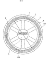
図1に、本発明の実施の形態1の例を示す。図1はインナーロータ型の永久磁石型同期発電機である。すなわち、図1においては、回転子100の外側に固定子101が位置している。図1において、1は固定子101を構成している固定子鉄心、2は固定子鉄心1に設けられた複数個のティース、3は隣接するティース2間に形成された凹部であるスロット、4は回転子100に設けられた複数の永久磁石、5は永久磁石4が等間隔に取り付けられている一体型の塊状の回転子ヨーク、6は回転子100の回転軸である。
【0026】
図1に示すように、回転子外径は3mであり、回転子100に設けられた永久磁石4の個数(すなわち、回転子磁極の極数)は64、固定子101のティース2およびスロット3の個数は共に96である。回転子100の塊状のヨーク5の表面に永久磁石4が配置された表面磁石型の同期発電機であり、固定子101は96個のティース2を有し、図1においては図示は省略しているが、各ティース2に電機子巻線が集中的に巻き回されたいわゆる集中巻の巻線方式を採用している。
【0027】
図2(a)は、図1の固定子101と回転子100の一部を模式的に示したものであり、図2(b),(c),(d)は、電機子電流が形成する起磁力波形を示したものである。図2において、8はティース2に巻き回された電機子巻線である。他の構成については、図1に示したものに相当するため、同一符号を付して示し、ここではその説明を省略する。本実施の形態では、回転子100の極数と固定子101のスロット数の比が2:3であるため、電磁気的に2極3スロット分が1つのユニットとなっている。したがって、2極3スロットについて考えればよい。固定子101には、図2(a)に示すように、U相、V相、W相の合計3相の電機子巻線8がスロット3に納められており、これらの電機子巻線8は各ティース2に集中的に巻き回されている。また、3相の電機子巻線8には、電気角120度ずつずれた正弦波状の電流が通電される。このように電機子巻線8に電流が流れると、空隙部に矩形波状の起磁力が発生する。例えば、U相に1の電流が流れているとき、V相,W相には−1/2の電流が流れていることになる。このとき、空隙部に発生する起磁力波形は図2(b)のようになる。実際は、3相の電流は時間ともに正弦波状に変化するため、この起磁力波形も変化する。この起磁力波形を時間、空間でフーリエ級数展開すると、回転子100と同期した起磁力成分と、非同期成分とがあることが分かる。
【0028】
図3に、起磁力のフーリエ級数展開した結果を示す。図3は、極数2Pとスロット数Sとの比が2P:S=2:3のときの固定子の起磁力のフーリエ解析結果を示したものである。横軸は2極(電気角360度)を基本波とした空間次数でありその符号が正のときは正相を示し、回転子100と同じ方向に回転する起磁力である。負は逆相を示し、回転子100の回転方向と逆方向に回転する起磁力である。縦軸はその成分の起磁力の振幅を表し、回転子と同期した成分すなわち+1次の大きさを1として規格化して示している。ただし、すべての調波成分について示したものではなく、15次以上の成分は省略している。この起磁力の各成分の中で、回転子100の磁極と同期した成分は横軸が+1次の成分で、この成分によってトルクが得られる。また、この起磁力成分は回転子100に固定した座標系からみると時間的に変化しない起磁力であるため、回転子100の渦電流の発生原因とならない。ところが、それ以外の成分は非同期成分であり、回転子100に固定した座標系から見ると時間的に変化するので、回転子100の渦電流の原因となっている。また、これら非同期成分の中では−2次の成分の振幅が最も大きい。図2(c),(d)に、同期成分(基本波の正相成分)と非同期成分の例として逆相の2次成分を示す。既に説明したように、この同期成分は渦電流の原因とならないが、非同期成分は回転子100に渦電流を発生させる。特に、このように極数とスロット数の比が2:3の場合には、逆相成分の中で2次成分の振幅が最も大きいため、回転子100に発生する渦電流損の主な原因といえる。本実施の形態にて扱っている発電機の極数は64極なので、この渦電流の主な原因となっている起磁力波形の空間次数は機械角360度を1次とすれば64次となる。
【0029】
次に、上記非同期成分によって発生する回転子100の渦電流を把握するために、簡易的なモデルを用いて近似的に導出することにする。さらに、その渦電流は原因になっている起磁力の非同期成分の次数Nと、回転子100の極対数Pと、回転子100の外径D[m]とは、どのような関係にあるのか、また、渦電流を低減するために上記N,Pをどのように選定すればよいかについて考えることにする。
【0030】
図4の上段は、渦電流の原因となる起磁力の非同期成分によって発生する磁束の時間的変化を示したものである。また、図4の下段は上記磁束の変化によって回転子100に生じる渦電流の経路と渦電流損を求める際に用いる微小回路(斜線部)を示したものであり、回転子100を空隙面から見下ろした様子を簡略化して示している。なお、図4において、w[m]は、渦電流の原因となる起磁力の1周期分の長さ、すなわち、波長であり、L[m]は、発電機のコア長である。また、xは周方向の位置を表す座標[m]で、yは軸方向の位置を表す座標[m]である。渦電流の流れる経路は、図4に示す通り、起磁力の半波長分の幅すなわちw/2の幅の範囲内で形成される。そこで、w/2の範囲内に図の斜線部に示すような周方向の幅2x、軸方向の幅2yでの位置に微小回路を考え、この微小回路の抵抗と回路に加わる起電力から渦電流損を求め、さらに空間的に積分することによって発電機全体に発生する渦電流損を算出する。
【0031】
まず、微小回路の抵抗r[Ω]を求める。抵抗rは抵抗率ρ[Ωm]と回路の長さに比例し、回路の断面積に反比例するので、
【0032】
【数10】
と表される。ただし、ここでδは渦電流の表皮深さであり単位はmである。図4から幾何学的に
【0034】
【数11】
が成り立つ。これを式(1)に代入すると、
【0036】
【数12】
となる。
【0038】
次に、この微小回路に掛かる起電力を求める。渦電流の原因となる磁束密度の非同期成分の時間的、空間的変化を
【0039】
【数13】
として表す。これは磁束密度の変化の空間的周波数は2π/wであり、その周波数はω[rad/sec]であることを示している。微小回路に掛かる起電力は区間[−x,x]の鎖交磁束の時間微分で表されるので、
【0041】
【数14】
となる。式(4)を式(5)に代入すると、
【0043】
【数15】
【0044】
【数16】
となる。微小回路のリアクタンスを無視すれば、微小回路に発生する渦電流損dQ[W]は式(3),(7)から
【0046】
【数17】
と求めることができる。この微小回路の渦電流損を区間[−w/4,w/4]で積分し、さらに渦電流の流れる経路は起磁力の半波長分の幅で形成されていたので、2N(=2πD/w)倍しないといけないので、回転子全体での渦電流損Q[W]は、
【0048】
【数18】
となる。さらに、表皮深さδについては、抵抗率ρ、透磁率μ、周波数ωとすると、
【0050】
【数19】
となる。ここで、通常発電機ではw<<Lであるので、
【0052】
【数20】
と近似できる。また、w=πD/Nであるから、式(9)(10)から
【0054】
【数21】
と近似できる。ただしKは
【0056】
【数22】
である。また、空間次数Nの非同期の起磁力によって発生する渦電流の角周波数ω[rad/sec]は発電機の回転数ωm[rad/sec]を用いると
【0058】
【数23】
と表される。ただし、式中の符号+は空間次数Nの起磁力が逆相のとき、−は正相のときに対応する。すなわち、回転子に固定した座標系から見ると、回転子と逆方向に進行する起磁力の周波数は高く、逆に回転子と同じ方向に進行する起磁力の周波数は低く見えるのである。したがって、Qは、式(11)(13)より
【0060】
【数24】
と書くことができる。
【0062】
図5〜8に集中巻にて良く用いられる様々な極数とスロット数の比に対して、起磁力の成分がどのようになっているかを示す。図5は、極数2Pとスロット数Sとの比が2P:S=4:3のときの固定子の起磁力のフーリエ解析結果を示したものであり、図6は、極数2Pとスロット数Sとの比が2P:S=10:9のときの固定子の起磁力のフーリエ解析結果を示したものであり、図7は、極数2Pとスロット数Sとの比が2P:S=8:9のときの固定子の起磁力のフーリエ解析結果を示したものであり、図8は、極数2Pとスロット数Sとの比が2P:S=10:12のときの固定子の起磁力のフーリエ解析結果を示したものである。
【0063】
分布巻の場合には、毎極毎相1や2の場合、起磁力の非同期成分は正相5次、逆相7次成分あるいはそれ以上であり、基本波より高次の成分である。しかしながら、集中巻の場合、基本波より高次の成分であっても分布巻に比べると基本波に近い次数に存在し、場合によっては基本波よりも低い成分にも非同期成分が存在することが分かる。さらに、渦電流の主たる原因になっている非同期成分の起磁力の空間次数をN(機械角360度を1次)とすればその大きさは極対数との比すなわちP/Nに比例する。さらに、図3、図5〜8から渦電流損の主たる原因となる起磁力すなわち非同期成分でもっとも振幅が大きいものは逆相であることも分かっている。したがって、式(14)は次のように書きかえることができる。
【0064】
【数25】
ただし、ここでK1は比例定数である。以上により、回転子に発生する渦電流損の近似式を導出できた。この式は永久磁石型の発電機あるいはモータにおいて、回転子に発生する渦電流損が極対数Pと回転子外径Dと逆相起磁力の空間次数Nに大きく依存していることを示している。
【0066】
一方、一般的に回転電機において回転子の外径Dと軸長Lと回転数ωmと出力Poutとの間には、おおよそ
【0067】
【数26】
なる関係があることが知られている。ただし、K2は比例定数である。したがって、式(15)を式(16)で除することにより、出力に対する渦電流損の割合を求めることができる。
【0069】
【数27】
式(17)中から発電機の構造によって決まる要素すなわち、極対数P、起磁力高調波の空間次数N、回転子外径Dを取り出し、これを発電機あるいはモータの回転子に発生する渦電流損の割合を評価するパラメータとしてX(単位はm)を
【0071】
【数28】
のように定義する。Xはもちろん厳密な意味で割合を示すものではないが、種々の発電機あるいはモータにおいてXを算出しその大きさを知ることにより、渦電流損の大小を判断する目安になると考えられる。
【0073】
ギヤレス型の風力発電機など低速で回転子が回転し、大きなトルクを必要とする発電機では式(16)からわかるように、軸長Lを大きくするより直径Dを大きくするほうが有利である。また、軸長Lと直径Dの比について考えると、Lが大きくなると軸受けのスパンが大きくなるため、剛性を補う必要が生じ、発電機の重量が増大する。また、風力発電においては軸受けが発電機の片側にのみ設けた構成になることがあるが、Lが大きくなると機械剛性が低下し、この構成が実現不可能となる。さらに、熱設計の観点からLが大きくなるとダクトを設けなければ冷却できなくなる。ダクトを設けるとLがさらに大きくなるため重量も大きくなるという課題がある。上記を鑑みて検討した結果、L≦Dであることが望ましく、より好ましくはL≦0.8D、さらにより好ましくはL≦0.5Dであることがわかった。
【0074】
図16に発電機の出力Poutに対するDをL=D、L=0.8D、L=0.5Dとした場合について示す。出力が大きくなるにつれて、Dを大きくする必要があることが分かる。また、風力発電用としては、先に述べた機械剛性や熱設計の観点からはL=Dとした場合の曲線より上の領域に設計されることが望ましく、さらにL=0.8Dとした場合より上の領域であることが望ましく、さらにはL=0.5Dとした場合より上の領域であることがより望ましい。したがって、図16から、出力が2000kWの場合、D≧2.2[m]、より好ましくはD≧2.3[m]、さらにより好ましくはD≧2.7[m]として設計されるのが望ましいことがわかる。出力が500kWの場合、D≧1.4[m]、より好ましくはD≧1.5[m]、さらにより好ましくはD≧1.8[m]であればよく。また、出力が100kWではD≧0.7[m]、より好ましくはD≧0.8[m]、さらにより好ましくはD≧0.9[m]とすればよいことが分かる。500kW以上の領域を直線近似すると、L=DのときはD=0.00045Pout+1.2、L=0.8DのときはD=0.00048Pout+1.3、L=0.5DのときはD=0.00057Pout+1.5と表される(この式でPoutの単位はkW、Dの単位はm)。したがって、この直線よりDが大きい領域に設計されることが望ましい。
【0075】
直線近似した場合、出力が小さい範囲では実際の曲線から外れることになる。しかし、発電機やモータの各容量のシリーズ化を考えたときには生産設備等の制限から外径はほぼ同じで、軸長で調整することが多い。したがって、ここでは出力が低い範囲においても外径が急に小さくならないよう直線近似を採用した。以上により、出力が小さくなっても極端に外径が小さくなることがないため、同じ生産設備でも出力の小さい発電機を製造できるという効果がある。
【0076】
ギヤレス型の風力発電用などでは100kWを超えるような大容量の場合、回転子外径Dと軸長Lの関係あるいはDの値を上記のように設計しておけば、トルクが大きくなりギヤレス型に適した設計となる他、薄型となることでダクトを設けなくとも冷却性能を確保できる等、熱設計も有利となるという効果があり、軸受けのスパンが短くなることで機械剛性を確保でき、片側にのみ軸受けを設けた構成も可能となるという効果もある。
【0077】
一方、Xを見ると、外径が大きい回転電機、特に回転子外径が1mを超えるような風力発電機を設計するにあたっては、P,Nを適切に選ばなければ回転子に発生する渦電流が無視できなくなると言える。
【0078】
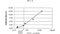
このパラメータの妥当性を検証するために、図9に示すような6種の仕様で、6通りの発電機を設計し、電磁界解析によって定格運転時に回転子に発生する渦電流損を求めた。図9の最右欄に、各仕様における定格出力に対する渦電流損の割合の解析結果を示す。さらに、横軸にXをとり縦軸に渦電流損の出力に対する割合をとったグラフを図10に示す。渦電流損の出力に対する割合とパラメータXの間には相関関係があることが分かる。
【0079】
次に、回転子の渦電流損を小さくし、高効率な発電機あるいはモータを設計する際にXをどのように選定すべきか考える。発電機あるいはモータの効率を95%以上に設計しようとすれば、固定子で発生する銅損と鉄損や機械損そして回転子の渦電流損を含む漂遊負荷損の合計を5%以内に設計する必要がある。機械損は銅損や鉄損に比べて一般的に小さいのであまり考慮しなくてもよい。銅損や鉄損は固定子の寸法、形状等である程度低減できるものの限界がある。そこで、総損失5%の半分すなわち2.5%まで回転子の渦電流損を低減できる構造にすれば、銅損や鉄損などの損失を合計した総損失を5%程度に抑えることができると考える。つまり、回転子の渦電流損を定格出力の2.5%程度に抑えることができれば、効率95%の高効率を達成できると考える。図10のグラフにおいて渦電流損の割合を2.5%以下にするには、Xの値を0.6[m]以下にしなければならないことから、
【0080】
【数29】
とすれば高効率な永久磁石型発電機あるいはモータを実現できると考えられる。図1の発電機は磁界解析の結果、回転子の渦電流損は定格出力の僅か0.6%であった。この発電機ではX=0.17[m]であり、当然のことながら式(19)をみたす。
【0082】
以上より、式(19)を満たす構造にすることにより、永久磁石型回転電機が大型化しても、回転子の渦電流の原因となる特定の電機子起磁力の空間次数Nを大きくすることができ、回転子に発生する渦電流を低減することが可能となる。その結果、回転子の発熱を抑制できるという効果があると同時に、回転電機の高効率化を図ることができるという効果もある。さらに、従来例に述べられているように回転子のヨークを区分したり、絶縁分割したりといった複雑でコストのかかる構造にしなくとも、本実施の形態においては、塊状の回転子ヨークを用いながら、回転子の渦電流損を低減することができるという効果がある。また、ここでは回転子の表面に磁石を備えた表面磁石型の回転電機について述べたが、回転子鉄心に磁石を埋め込んだ埋め込み磁石型についても電機子起磁力の非同期成分が磁石等の渦電流損の原因になっている点では共通である。したがって、埋め込み磁石型の回転電機についても本実施の形態の構成にすることによって同様の効果が得られることは言うまでもない。
【0083】
また、本実施の形態においては、インナーロータ型について述べたが、回転子が固定子の外側を回転する、アウタロータ型でも同じ効果が得られることがいうまでもない。さらに、本実施の形態で述べたラジアルギャップ型だけではなく、固定子と回転子が回転軸に垂直な面で対向するアキシャルギャップ型でも、回転軸から回転子磁極までの距離を回転子の半径と定義しその2倍の値を直径Dとして定義すれば同じ効果が得られることはいうまでもない。
【0084】
実施の形態2.
本実施の形態においては、実施の形態1で示した永久磁石型回転電機と同様に、永久磁石による複数の磁極を有する回転子と電機子巻線を磁極に巻き回された固定子とを備えた風力発電用永久磁石型同期発電機に対して、上記実施の形態1で示した式(19)を満たす構成を適用した例について説明する。図11及び図12に風力発電システムの概念図を示す。これらの図において、10は風力発電システムの支柱となるタワーであり、11はタワー10上に設けられたナセルである。ナセル11の内部には、図11の例では、発電機12と増速ギヤ13とが設けられており、図12の例では、発電機12のみが設けられている。14はナセル11の先端に設けられた風車であり、15及び16は、それぞれ、風車14を構成しているハブとブレードである。なお、回転子および固定子の構造については、上述の実施の形態1で示した図1のものと同様であるため、ここでは説明を省略する。
【0085】
このように、図11の例においては、タワー10の上にナセル11があり、ナセル11内部に発電機12と増速ギヤ13が納められており、その先に風車14が接続されている。ハブ15とブレード16で構成される風車14と発電機12とは増速ギヤ13を介して接続されている。このシステムでは、増速ギヤ13を介することで、発電機12の回転数を風車14の回転数より高くしているので、発電機12のトルクが小さくてすみ、発電機12は小型化が可能であるという利点がある。しかしながら、増速ギヤ13の発生する騒音や増速ギヤ13のメンテナンスなどの課題がある。一方、近年、図12に示すように、風車14と発電機12が直結されたいわゆるギヤレス型の風力発電システムが普及しつつある。当該ギヤレス型のものは、さらに、巻線界磁型の同期発電機に比べて、界磁損失がないという点で永久磁石型同期発電機が有利となる。
【0086】
このシステムでは増速ギヤに起因する騒音やメンテナンスの課題はないが、発電機のトルクがギヤレス型に比べて大きくなるため、発電機自体の体格が大きくなる。これまで説明してきたように、式(18)によれば、発電機の回転子外径Dが大きくなると回転子の渦電流損が大きくなる。したがって、極数Pとスロット数Sの選定が適切でないと、渦電流損が大きくなってしまい、界磁損失がないという永久磁石型同期発電機の利点を生かしきれないことになる。
【0087】
したがって、風力発電用永久磁石型同期発電機、特にギヤレス型風力発電システムに組みこまれるような回転子径が大きな永久磁石型同期発電機においては、式(19)をみたす構造にすることにより、回転子の渦電流損を低減でき、回転子の発熱を抑制できるのと同時に、発電機の高効率化が図れるため、風力という自然エネルギーの有効利用ができるという効果がある。
【0088】
実施の形態3.
これまで述べてきたように、固定子が集中巻の大型の永久磁石型発電機やモータにおいては、極対数Pと渦電流の原因となる起磁力の空間次数Nを適切に選ばないと回転子の渦電流損が非常に大きくなることがある。換言すれば、極対数Pとスロット数Sを適切に選定しないと渦電流による発熱や、効率低下が懸念される。一方、集中巻の回転電機の極数2Pとスロット数Sには様々な組み合わせが考えられる。良く用いられる組み合わせとして、2P:S=4:3,10:9,8:9,10:12,2:3となる組み合わせなどある。ここでは、これら5通りの組み合わせについて極数が60極程度になるように、64極48スロット、60極54スロット、64極72スロット、60極72スロット、64極96スロットとして、回転子外径3mの同一出力の永久磁石型同期発電機を設計することを考えた。なお、ここでは回転子に発生する渦電流損の比較を行うため、条件を同じにするため回転数は同一としている。また、スロット開口部のパーミアンスの変化の影響が大きくならないように、スロット開口幅もほぼ同じ設計としている。これら5種類の発電機について電磁界解析により定格運転時に回転子に発生する渦電流損を求めた。図13にそれぞれの渦電流損の出力に対する割合を示す。この結果から、極数2Pをほぼ同じに設計しても、極数とスロット数の組み合わせによって渦電流損が大きく違うことが分かる。さらに、横軸にスロット数と極数の比S/2Pを横軸にとってグラフにしたものを図14に示す。この結果から、S/2P>1すなわち2P<Sの場合には渦電流損が小さく、逆にS/2P<1すなわち2P>Sのときには渦電流損が大きいことが分かる。
【0089】
この原因を考察してみる。図3と図5〜8から、渦電流の主たる原因になっている起磁力の非同期成分の空間次数Nを見ると、2P:S=4:3,10:9すなわち2P>Sとなる組み合わせでは同期成分よりも次数の低いところに同期成分と同等あるいはそれ以上の振幅の非同期に起磁力成分が存在する。具体的には2P:S=4:3のときには−1/2次で振幅は同期成分の2倍、2P:S=10:9のときには−4/5次で振幅は同期成分の1.25倍の起磁力が存在する。ところが、2P:S=8:9,10:12,2:3すなわち2P<Sとなる組み合わせでは同期成分よりも次数の低いところに振幅の大きな非同期の起磁力成分が存在しない。ここでは、極対数は30か32でほぼ一定、回転子外径Dも一定であるから、回転子の渦電流損の大きさは式(18)より起磁力の空間次数Nに依存する。したがって、大型の集中巻の永久磁石型回転電機を設計する場合には2P<Sとした方が、Nを小さく設計できるので渦電流損は小さくなると言える。もちろん、2P>Sとした場合でも極数を増やして式(19)をみたす構造とすると、渦電流損は低減できる。しかしながら、2P<Sとした場合に比べて、パラメータXの値を同じに設計しようとすると極数が増えるため加工費が上がり不利である。
【0090】
以上より、大形の永久磁石型回転電機においては、2P<Sをみたす構造にすることにより、回転子の渦電流損を低減でき回転子の発熱を抑制できるのと同時に、発電機の高効率化が図れるという効果がある。さらに、渦電流損を低減する構成とした場合、2P<Sとした場合に比べて、極数が少なくなるため加工費が少なく低コストの永久磁石型回転電機を提供できるという効果がある。
【0091】
特に、同じかほぼ同じ極数で集中巻の回転電機を設計した場合に2P:S=2:3のときには他に比べてNは最も大きくなるため極数をもっとも少なく構成できるため非常に有利である。図3から2P:S=2:3のとき渦電流の主たる原因となるのは2次の逆相の起磁力であるから、2P極の場合はN=2Pとなる。これを式(19)に代入すると、
【0092】
【数30】
を得る。
【0094】
したがって、集中巻で極対数Pとスロット数Sの組み合わせが2P:S=2:3なる永久磁石型回転電機において式(20)をみたすような構成にしたことにより、渦電流の原因となる電機子起磁力の特定の調波成分の空間次数Nを大きくするのに、特に少ない極数で実現可能なので、回転子の渦電流損を低減できるという効果があるとともに磁極の加工費を特に少なくできるという効果がある。
【0095】
一方、2P<Sをみたす集中巻の永久磁石型回転電機において2P:S=8:9,10:12なる関係が成り立つ場合についても同様に考える。2P:S=8:9の場合には、図7より5/4次の逆相起磁力が渦電流の主な原因となっているからN=5P/4を式(19)に代入して、
【0096】
【数31】
を得る。したがって、2P:S=8:9の場合には式(21)をみたす構成とすることにより、回転子に発生する渦電流を低減し、回転子の発熱を抑制できるとともに、高効率な永久磁石型回転電機を提供できるという効果がある。また、2P:S=10:12の場合には、図8より7/5次の逆相起磁力が渦電流の主な原因となっており、N=7P/5を式(19)に代入して、
【0098】
【数32】
を得る。したがって、2P:S=10:12の場合には式(22)をみたす構成とすることにより、回転子に発生する渦電流を低減し、回転子の発熱を抑制できるとともに、高効率な永久磁石型回転電機を提供できるという効果がある。
【0100】
また、2P:S=8:9、2P:S=10:12の組み合わせの集中巻の永久磁石型回転電機は巻線係数が2P:S=4:3,2:3の0.866に比べて高くぞれぞれ0.945、0.933である。このため磁石の使用量を小さくでき低コストな回転電機を提供できるという効果がある。また、同じまたはほぼ同じ極数で回転電機を設計した場合には、極数とスロット数の最小公倍数が2P:S=4:3,2:3の場合にくらべて大きくなる。例えば、64極48スロット(2P:S=4:3)、64極96スロット(2P:S=2:3)の場合はともに192であるのに対し、64極72スロット(2P:S=8:9)では576、60極72スロット(2P:S=10:12)では360となる。一般には、最小公倍数が大きいほどコギングトルクが小さい。したがって、2P:S=8:9、10:12にすることにより、コギングトルクの小さな永久磁石型回転電機を得ることができる。特に風力発電用の永久磁石型同期発電機においては、コギングトルクが大きいと風車の起動に必要が風速が大きくなり不利になる。したがって、2P:S=8:9、10:12にすることによりコギングトルクが小さくなり、結果として風速が小さくとも風車が起動し発電を開始することができるという効果がある。
【0101】
以上より、集中巻で極対数Pとスロット数Sの組み合わせが2P:S=8:9あるいは10:12なる永久磁石型回転電機においてそれぞれ式(21)、(22)をみたすような構成にしたことにより、渦電流の原因となる電機子起磁力の特定の調波成分の空間次数Nを大きくするのに、2P>Sの場合に比べて少ない極数で実現可能なので、回転子の渦電流損を低減できるという効果があるとともに磁極の加工費を特に少なくできるという効果がある。さらに、巻線係数が高いため、磁石の使用量を少なくすることができるため低コストな回転電機を提供できるという効果がある。また、極数とスロット数の最小公倍数が大きいため、コギングトルクが小さく、風速が小さくとも風車が起動し発電を開始することができるという効果もある。
【0102】
実施の形態4.
図15に本実施の形態を示す。本実施の形態においては、図15に示すように、回転子のヨーク5の表面に永久磁石4が固定されており、また、この永久磁石4は回転子の軸方向に分割された構成となっている。また、分割された個々の永久磁石4の間は電気的に絶縁されている。他の構成については、上記の実施の形態1と同様であるため、ここでは説明を省略する。
【0103】
近年、希土類系の磁石がよく用いられるようになっているが、希土類磁石は導電率が高いため、渦電流が問題になることがある。そこで、これまで述べたように極対数Pと起磁力の空間次数Nと回転子の外径Dを式(19)をみたすような組み合わせとし、さらに、図15に示すように永久磁石4を分割した構成にすることにより、回転子全体における渦電流損を低減できる他、磁石自身に発生する渦電流損を大幅に低減し、永久磁石4の発熱を抑制することができる上、高効率な永久磁石型回転電機を得ることができるという効果がある。
【0104】
以下にこの発明の効果を述べる。
【0105】
この発明は、永久磁石による複数の磁極を有する回転子と電機子巻線がティースに集中的に巻き回された固定子とを有する永久磁石型回転電機であって、上記回転子の磁極の極対数をP、上記回転子の直径をD[m]とし、上記固定子の電機子起磁力の所定の調波成分の空間次数をN(機械角360度を1次とする)とし、上記永久磁石型回転電機の出力をPoutとして、上記DをD=0.00045Pout+1.2以上としたとき、上記回転子に発生する渦電流損の割合を評価するパラメータX(単位はm)を
X=(N+P)1.5N-4P2D
と定義し、上記Xの値が所定の値より小さくなるように、上記、P、D、Nの値を選択する構成とした永久磁石型回転電機であるので、このような構成としたことにより、永久磁石型回転電機が大形化しても、回転子の渦電流の原因となる特定の電機子起磁力の空間次数Nを大きくすることができ、回転子に発生する渦電流を低減することが可能となる。その結果、回転子の発熱を抑制できるという効果があると同時に、回転電機の高効率化を図ることができるという効果もある。さらに、従来例に述べられているように回転子のヨークを区分したり、絶縁分割したりといった複雑でコストのかかる構造にしなくとも、ヨークを一体型にした構造を保ちつつ、回転子の渦電流損を低減することができるという効果がある。
【0106】
また、この発明は、永久磁石による複数の磁極を有する回転子と電機子巻線がティースに集中的に巻き回された固定子とを有する永久磁石型回転電機であって、上記回転子の磁極の極対数をP、上記回転子の直径をD[m]とし、上記固定子の電機子起磁力の所定の調波成分の空間次数をN(機械角360度を1次とする)とし、上記永久磁石型回転電機の出力をPoutとして、上記DをD=0.00045Pout+1.2以上としたとき、上記、P、D、Nが
【0107】
【数33】
を満たす構成とした永久磁石型回転電機であるので、このような構成としたことにより、永久磁石型回転電機が大形化しても、回転子の渦電流の原因となる特定の電機子起磁力の空間次数を大きくすることができ、回転子に発生する渦電流を低減することが可能となる。その結果、回転子の発熱を抑制できるという効果があると同時に、回転電機の高効率化を図ることができるという効果もある。さらに、従来例に述べられているように回転子のヨークを区分したり、絶縁分割したりといった複雑でコストのかかる構造にしなくとも、ヨークを一体型にした構造を保ちつつ、回転子の渦電流損を低減することができるという効果がある。
【0109】
また、上記固定子のスロット数をSとしたとき、上記Pと上記Sとが、2P<Sの関係を満たすようにしたので、このような構成にしたことにより、渦電流の原因となる電機子起磁力の特定の調波成分の空間次数Nを大きくするのに、2P>Sである永久磁石型回転電機と比較して、少ない極数で実現可能なので、回転子の渦電流損を低減できるという効果があるとともに磁極の加工費を少なくできるという効果がある。
【0110】
また、上記固定子のスロット数をSとしたとき、上記Pと上記Sとが、2P:S=2:3の関係を満たすとともに、上記Pと上記Dとが、
【0111】
【数34】
の関係を満たす構成としたので、このような構成にしたことにより、渦電流の原因となる電機子起磁力の特定の調波成分の空間次数Nを大きくするのに、特に少ない極数で実現可能なので、回転子の渦電流損を低減できるという効果があるとともに磁極の加工費を特に少なくできるという効果がある。
【0113】
また、上記固定子のスロット数をSとしたとき、上記Pと上記Sとが、2P:S=8:9の関係を満たすとともに、上記Pと上記Dとが、
【0114】
【数35】
の関係を満たすようにしたので、このような構成にしたことにより、渦電流の原因となる電機子起磁力の特定の調波成分の空間次数Nを大きくするのに、少ない極数で実現可能なので、回転子の渦電流損を低減できるという効果があるとともに、磁極の加工費を少なくできるという効果がある。さらに、極数とスロット数の最小公倍数が大きいためコギングトルクを低減できるという効果がある。また巻線係数が高いため磁石の使用量を低減できるので、低コスト化が図れるという効果がある。
【0116】
また、上記固定子のスロット数をSとしたとき、上記Pと上記Sとが、2P:S=10:12の関係を満たすとともに、上記Pと上記Dとが、
【0117】
【数36】
の関係を満たすようにしたので、このような構成にしたことにより、渦電流の原因となる電機子起磁力の特定の調波成分の空間次数Nを大きくするのに、少ない極数で実現可能なので、回転子の渦電流損を低減できるという効果があるとともに回転子の渦電流損を低減できるという効果がある。さらに、極数とスロット数の最小公倍数が大きいためコギングトルクを低減できるという効果がある。また巻線係数が高いため磁石の使用量を低減できるので、低コスト化が図れるという効果がある。
【0119】
また、上記回転子の磁極を構成する上記永久磁石を軸方向に分割して区分構造としたことにより、磁石に発生する渦電流損を低減することができるため磁石の発熱を抑制することができる上、高効率な永久磁石型回転電機を得ることができるという効果がある。
【0120】
また、この発明は、永久磁石による複数の磁極を有する回転子と電機子巻線がティースに集中的に巻き回された固定子とを有する風力発電用永久磁石型同期発電機であって、上記回転子の磁極の極対数をP、上記回転子の直径をD[m]とし、上記固定子の電機子起磁力の所定の調波成分の空間次数をN(機械角360度を1次とする)とし、上記永久磁石型回転電機の出力をPoutとして、上記DをD=0.00045Pout+1.2以上としたとき、上記回転子に発生する渦電流損の割合を評価するパラメータX(単位はm)を
X=(N+P)1.5N-4P2D
と定義し、上記Xの値が所定の値より小さくなるように、上記、P、D、Nの値を選択する構成とした風力発電用永久磁石型同期発電機であるので、このような構成とするとすることにより、風力発電用永久磁石型同期発電機、特にギヤレス型風力発電システムに組みこまれる回転子径が1mを超えるような大形の永久磁石型同期発電機においても、回転子に発生する渦電流損を低減することができ、結果として回転子の発熱を抑制することができると同時に発電機の高効率化を実現できる。さらに、従来例に述べられているように回転子のヨークを区分したり、絶縁分割したりといった複雑でコストのかかる構造にしなくとも、ヨークを一体型にした構造を保ちつつ、回転子の渦電流損を低減することができるという効果がある。
【0121】
また、この発明は、永久磁石による複数の磁極を有する回転子と電機子巻線がティースに集中的に巻き回された固定子とを有する風力発電用永久磁石型同期発電機であって、上記回転子の磁極の極対数をP、上記回転子の直径をD[m]とし、上記固定子の電機子起磁力の所定の調波成分の空間次数をN(機械角360度を1次とする)とし、上記永久磁石型回転電機の出力をPoutとして、上記DをD=0.00045Pout+1.2以上としたとき、上記、P、D、Nが
【0122】
【数37】
を満たす構成とした風力発電用永久磁石型同期発電機であるので、このような構成とするとすることにより、風力発電用永久磁石型同期発電機、特にギヤレス型風力発電システムに組みこまれる回転子径が1mを超えるような大形の永久磁石型同期発電機においても、回転子に発生する渦電流損を低減することができ、結果として回転子の発熱を抑制することができると同時に発電機の高効率化を実現できる。さらに、従来例に述べられているように回転子のヨークを区分したり、絶縁分割したりといった複雑でコストのかかる構造にしなくとも、ヨークを一体型にした構造を保ちつつ、回転子の渦電流損を低減することができるという効果がある。
【0124】
産業上の利用可能性
以上のように、本発明の永久磁石型回転電機は、風力発電等の種々の発電に用いると有用である。
【図面の簡単な説明】
【図1】 本発明の実施の形態1による永久磁石型同期発電機の構成を示した断面図である。
【図2】 本発明の実施の形態1による永久磁石型同期発電機における電機子起磁力を示した説明図である。
【図3】 本発明の実施の形態1による永久磁石型同期発電機における起磁力波形のフーリエ解析結果(極数:スロット数=2:3のとき)を示した説明図である。
【図4】 本発明の実施の形態1による永久磁石型同期発電機における磁束の時間的変化と回転子に生じる渦電流の経路を示した説明図である。
【図5】 本発明の実施の形態1による永久磁石型同期発電機における起磁力波形のフーリエ解析結果(極数:スロット数=4:3のとき)を示した説明図である。
【図6】 本発明の実施の形態1による永久磁石型同期発電機における起磁力波形のフーリエ解析結果(極数:スロット数=10:9のとき)を示した説明図である。
【図7】 本発明の実施の形態1による永久磁石型同期発電機における起磁力波形のフーリエ解析結果(極数:スロット数=8:9のとき)を示した説明図である。
【図8】 本発明の実施の形態1による永久磁石型同期発電機における起磁力波形のフーリエ解析結果(極数:スロット数=10:12のとき)を示した説明図である。
【図9】 本発明の実施の形態1による永久磁石型同期発電機の仕様の例を示した説明図である。
【図10】 本発明の実施の形態1による永久磁石型同期発電機におけるパラメータXと渦電流損の割合の変化を示した説明図である。
【図11】 本発明の実施の形態2による風力発電システムの構成を示した構成図である。
【図12】 本発明の実施の形態2による風力発電システムの他の例を示した構成図である。
【図13】 本発明の実施の形態3による永久磁石型発電機における極数スロット数の組み合わせによる渦電流損の割合を示した説明図である。
【図14】 本発明の実施の形態3による永久磁石型発電機における(スロット数/極数)に対する渦電流損の割合を示した説明図である。
【図15】 本発明の実施の形態4による永久磁石型同期発電機の構成を示した部分斜視図である。
【図16】 本発明の実施の形態1による永久磁石型同期発電機における発電機の出力と回転子外径との関係を示した説明図である。[0001]
BACKGROUND OF THE INVENTION
The present invention relates to a permanent magnet type rotary electric machine and a permanent magnet type synchronous generator for wind power generation, and in particular, includes a rotor having a plurality of magnetic poles made of permanent magnets and a stator having armature windings wound around the magnetic poles. The present invention relates to a permanent magnet type rotating electric machine and a permanent magnet type synchronous generator for wind power generation.
[0002]
[Prior art]
Conventionally, a so-called concentrated winding permanent magnet type rotating electrical machine including a rotor having a plurality of magnetic poles by permanent magnets and a stator in which armature windings are intensively wound around the magnetic poles has been used for various applications. ing. Concentrated winding has a structure that is concentratedly wound around the magnetic poles of the stator, and therefore can be automatically wound by a machine. Therefore, concentrated winding is often used mainly for small motors such as servo motors. In such a small motor, copper loss, iron loss, and mechanical loss account for most of the loss, and eddy current loss generated in the rotor is not a problem in most cases.
[0003]
On the other hand, in large machines exceeding several kW, distributed winding has been often used so far, but the need for concentrated winding with a small coil end is also increasing in large machines. For example, when adopting a permanent magnet type synchronous generator in wind power generation, especially gearless type wind power generation system, compared with distributed winding, concentrated winding can reduce the axial length because the coil end is small, Furthermore, it can be said that it is better to select concentrated winding because the copper loss generated in the armature winding is small and high efficiency can be realized.
[0004]
As described above, concentrated winding has advantages such as small coil end and automatic winding. On the other hand, rotor eddy current loss due to magnetomotive force of armature current is smaller than distributed winding. I have the problem of getting bigger. In recent years, high-performance magnets having high residual magnetic flux density and high coercive force such as rare earth magnets have been actively used as magnetic poles for rotors of large capacity machines. For example, Nd-Fe-B series This magnet has a high electrical conductivity and has a feature that eddy current flows more easily than a ferrite magnet.
[0005]
For the above reasons, in a concentrated-winding large-capacity machine, particularly in a permanent magnet type rotating electric machine or a permanent magnet type synchronous generator for wind power generation in which the diameter of the rotor exceeds 1 m, eddy current generated in the rotor In some cases, the loss may reach a level that cannot be ignored. This eddy current loss significantly reduces the efficiency of the rotating machine, and the eddy current loss increases the temperature of the rotor, leading to demagnetization of the magnet. Further, even if demagnetization is not reached, the residual magnetic flux density decreases due to temperature rise, and as a result, the magnetic flux generated by the magnet decreases. For this reason, in order to produce the same output as that without temperature rise, it is necessary to flow a large amount of armature current, and there is a problem that copper loss increases and efficiency decreases.
[0006]
As a technique for solving such a problem, there has conventionally been a technique for reducing eddy current by forming a rotor yoke with a laminated steel plate. Japanese Patent Laid-Open No. 2001-54271 discloses that a rotor iron core is not a laminated steel plate but is formed of a massive yoke, and the yoke is divided to cut off the eddy current path, thereby reducing the eddy current. A technique is disclosed.
[0007]
However, when the rotor yoke has a laminated structure, there is a problem that the cost is higher than the case where the rotor yoke is configured as a block yoke. Further, when the block yoke is divided as described in JP-A-2001-54271, the following is given. This causes various problems. For example, there is a problem that the processing cost increases compared to an integral lump yoke and the cost is high, and furthermore, when the thickness of the insulating portion provided in the yoke of the rotor varies in each insulating portion, There is also a concern that the magnetic flux density in the gap of the motor also varies, resulting in non-uniform electromagnetic force, leading to noise and vibration. In addition, since there is an insulating portion for electrically insulating and dividing in order to divide the yoke, the magnetomotive force is consumed at that portion, leading to a problem that the output of the rotating electrical machine is reduced.
[0008]
[Problems to be solved by the invention]
As described above, in the conventional permanent magnet type rotary electric machine and the permanent magnet type synchronous generator for wind power generation, etc., in order to reduce the overcurrent, the rotor yoke has a laminated structure or the bulk yoke is divided. However, when a laminated structure is used, there is a problem that the processing cost increases and the cost is increased, and when the massive yoke is divided, the magnetic flux density in the gap of the motor varies, resulting in a problem. However, there was a problem that the electromagnetic force was unevenly connected. Therefore, it can be said that it is desirable that the rotor yoke be an integral type.
[0009]
The present invention has been made to solve such a problem, and a permanent magnet type rotating electrical machine and a wind turbine capable of reducing eddy current loss of a rotor while maintaining a structure in which a rotor yoke is integrated. The purpose is to obtain a permanent magnet synchronous generator for power generation.
[0010]
[Means for Solving the Problems]
The present invention relates to a permanent magnet type rotating electric machine having a rotor having a plurality of magnetic poles made of permanent magnets and a stator in which armature windings are concentrated around teeth.Manufacturing method and permanent magnet synchronous generator for wind power generationThe number of pole pairs of the magnetic poles of the rotor is P, the diameter of the rotor is D [m], and the spatial order of a predetermined harmonic component of the armature magnetomotive force of the stator is N (mechanical angle 360). The output of the permanent magnet type rotating electrical machine is Pout [KW]And D = 0.00045Pout+1.2 or moreSet to beParameter X (unit: m) for evaluating the ratio of eddy current loss generated in the rotor
X = (N + P)1.5N-FourP2D
And defineIfSelect the values of P, D, and N so that the value of X is smaller than a predetermined value.And attach 2P permanent magnets to the rotorPermanent magnet type rotating electric machineManufacturing methodAnd permanent magnet synchronous generator for wind power generationManufacturing methodIt is.
[0011]
The present invention also relates to a permanent magnet type rotating electric machine having a rotor having a plurality of magnetic poles made of permanent magnets and a stator in which armature windings are intensively wound around teeth.Manufacturing method and permanent magnet synchronous generator for wind power generationThe number of pole pairs of the magnetic poles of the rotor is P, the diameter of the rotor is D [m], and the spatial order of a predetermined harmonic component of the armature magnetomotive force of the stator is N (mechanical angle 360). The output of the permanent magnet type rotating electrical machine is Pout [KW]And D = 0.00045Pout+1.2 or moreSet to be, P, D, N above
[0012]
[Formula 6]
It is assumed that the configuration satisfiesIf,the abovePermanent magnet type rotating electric machine which does not divide rotor yoke of rotor in circumferential directionManufacturing methodAnd permanent magnet synchronous generator for wind power generationManufacturing methodIt is.
[0014]
Further, assuming that the number of slots of the stator is S, the P and S satisfy the
[0015]
Further, when the number of slots of the stator is S, the P and the S satisfy the
[0016]
[Expression 7]
It is set as the structure which satisfy | fills this relationship.
[0018]
Further, when the number of slots of the stator is S, the P and the S satisfy the relationship of 2P: S = 8: 9, and the P and the D are
[0019]
[Equation 8]
It is set as the structure which satisfy | fills this relationship.
[0021]
Further, when the number of slots of the stator is S, the P and the S satisfy the relationship of 2P: S = 10: 12, and the P and the D are
[0022]
[Equation 9]
It is set as the structure which satisfy | fills this relationship.
[0024]
Further, the permanent magnet constituting the magnetic pole of the rotor is divided in the axial direction to form a segmented structure.
[0025]
DETAILED DESCRIPTION OF THE INVENTION
FIG. 1 shows an example of
[0026]
As shown in FIG. 1, the outer diameter of the rotor is 3 m, the number of
[0027]
FIG. 2A schematically shows a part of the
[0028]
FIG. 3 shows the result of Fourier series expansion of the magnetomotive force. FIG. 3 shows the result of Fourier analysis of the magnetomotive force of the stator when the ratio of the number of
[0029]
Next, in order to grasp the eddy current of the
[0030]
The upper part of FIG. 4 shows the temporal change of the magnetic flux generated by the asynchronous component of the magnetomotive force that causes eddy current. The lower part of FIG. 4 shows a path of eddy current generated in the
[0031]
First, the resistance r [Ω] of the microcircuit is obtained. The resistance r is proportional to the resistivity ρ [Ωm] and the circuit length, and inversely proportional to the circuit cross-sectional area.
[0032]
[Expression 10]
It is expressed. Where δ is the skin depth of the eddy current and the unit is m. Geometrically from Figure 4
[0034]
## EQU11 ##
Holds. Substituting this into equation (1) gives
[0036]
[Expression 12]
It becomes.
[0038]
Next, the electromotive force applied to this microcircuit is obtained. Temporal and spatial change of asynchronous component of magnetic flux density causing eddy current
[0039]
[Formula 13]
Represent as This indicates that the spatial frequency of the change in magnetic flux density is 2π / w, and the frequency is ω [rad / sec]. Since the electromotive force applied to the microcircuit is represented by the time derivative of the interlinkage magnetic flux in the section [−x, x],
[0041]
[Expression 14]
It becomes. Substituting equation (4) into equation (5),
[0043]
[Expression 15]
[0044]
[Expression 16]
It becomes. If the reactance of the microcircuit is ignored, the eddy current loss dQ [W] generated in the microcircuit can be calculated from the equations (3) and (7).
[0046]
[Expression 17]
It can be asked. Since the eddy current loss of this microcircuit is integrated in the interval [−w / 4, w / 4], and the path through which the eddy current flows is formed with a width corresponding to the half wavelength of the magnetomotive force, 2N (= 2πD / w) Since it must be multiplied, the eddy current loss Q [W] in the entire rotor is
[0048]
[Formula 18]
It becomes. Furthermore, regarding the skin depth δ, assuming that the resistivity ρ, the permeability μ, and the frequency ω,
[0050]
[Equation 19]
It becomes. Here, since w << L in a normal generator,
[0052]
[Expression 20]
Can be approximated. Also, since w = πD / N, from equations (9) and (10)
[0054]
[Expression 21]
Can be approximated. Where K is
[0056]
[Expression 22]
It is. Further, the angular frequency ω [rad / sec] of the eddy current generated by the non-synchronous magnetomotive force of the spatial order N is the rotational speed ω of the generator.mWhen [rad / sec] is used
[0058]
[Expression 23]
It is expressed. However, the sign + in the formula corresponds to the case where the magnetomotive force of the spatial order N is in the opposite phase, and the sign-corresponds to the case in the positive phase. That is, when viewed from the coordinate system fixed to the rotor, the frequency of the magnetomotive force traveling in the direction opposite to the rotor is high, and conversely, the frequency of the magnetomotive force traveling in the same direction as the rotor is low. Therefore, Q is obtained from equations (11) and (13).
[0060]
[Expression 24]
Can be written.
[0062]
FIGS. 5 to 8 show the magnetomotive force components for various ratios of the number of poles and the number of slots often used in concentrated winding. FIG. 5 shows a Fourier analysis result of the magnetomotive force of the stator when the ratio of the number of
[0063]
In the case of the distributed winding, in the case of 1 or 2 for each pole, the asynchronous component of the magnetomotive force is the positive fifth-order component, the reverse-phase seventh-order component or more, and is a higher-order component than the fundamental wave. However, in the case of concentrated winding, even higher-order components than the fundamental wave are present in an order closer to the fundamental wave than in the distributed winding, and in some cases, asynchronous components may also exist in components lower than the fundamental wave. I understand. Further, if the spatial order of the magnetomotive force of the asynchronous component that is the main cause of the eddy current is N (mechanical angle of 360 degrees is the primary), the magnitude is proportional to the ratio of pole pairs, that is, P / N. 3 and 5 to 8, it is also known that the magnetomotive force that is the main cause of the eddy current loss, that is, the asynchronous component having the largest amplitude is in reverse phase. Therefore, equation (14) can be rewritten as follows.
[0064]
[Expression 25]
Where K1Is a proportionality constant. From the above, an approximate expression of the eddy current loss generated in the rotor can be derived. This equation shows that in a permanent magnet generator or motor, the eddy current loss generated in the rotor greatly depends on the pole pair number P, the rotor outer diameter D, and the spatial order N of the counter-phase magnetomotive force. Yes.
[0066]
On the other hand, generally in a rotating electrical machine, the outer diameter D, the axial length L, and the rotational speed ω of the rotormAnd output PoutApproximately between
[0067]
[Equation 26]
It is known that there is a relationship. However, K2Is a proportionality constant. Therefore, the ratio of the eddy current loss to the output can be obtained by dividing Expression (15) by Expression (16).
[0069]
[Expression 27]
From the equation (17), elements determined by the generator structure, that is, the number P of pole pairs, the spatial order N of magnetomotive force harmonics, and the outer diameter D of the rotor are taken out and eddy currents generated in the rotor of the generator or motor are extracted. X (unit: m) as a parameter to evaluate the loss ratio
[0071]
[Expression 28]
Define as follows. Of course, X does not indicate a ratio in a strict sense, but it is considered that it becomes a standard for determining the magnitude of eddy current loss by calculating X in various generators or motors and knowing the magnitude thereof.
[0073]
As can be seen from the equation (16), it is more advantageous to increase the diameter D than to increase the shaft length L in a generator in which the rotor rotates at a low speed such as a gearless type wind power generator and a large torque is required. Considering the ratio between the shaft length L and the diameter D, if L is increased, the span of the bearing is increased, so that it is necessary to supplement the rigidity, and the weight of the generator is increased. In wind power generation, the bearing may be provided only on one side of the generator. However, as L increases, the mechanical rigidity decreases, and this configuration cannot be realized. Furthermore, if L becomes large from the viewpoint of thermal design, cooling cannot be performed unless a duct is provided. When the duct is provided, L is further increased, which causes a problem that the weight is increased. As a result of considering the above, it has been found that L ≦ D is desirable, more preferably L ≦ 0.8D, and even more preferably L ≦ 0.5D.
[0074]
Fig. 16 shows the output P of the generator.outThe case where D is L = D, L = 0.8D, and L = 0.5D is shown. It can be seen that D needs to increase as the output increases. For wind power generation, it is desirable to design the region above the curve when L = D from the viewpoint of mechanical rigidity and thermal design described above, and when L = 0.8D. The upper region is desirable, and more desirably the region above L = 0.5D. Therefore, from FIG. 16, when the output is 2000 kW, D ≧ 2.2 [m], more preferably D ≧ 2.3 [m], and even more preferably D ≧ 2.7 [m] is designed. It turns out that is desirable. When the output is 500 kW, D ≧ 1.4 [m], more preferably D ≧ 1.5 [m], and even more preferably D ≧ 1.8 [m]. It can also be seen that when the output is 100 kW, D ≧ 0.7 [m], more preferably D ≧ 0.8 [m], and even more preferably D ≧ 0.9 [m]. When a region of 500 kW or more is approximated by a straight line, when L = D, D = 0.00045PoutWhen +1.2 and L = 0.8D, D = 0.00048PoutWhen +1.3 and L = 0.5D, D = 0.00057Pout+1.5 (In this equation, PoutUnit of kW, unit of D is m). Therefore, it is desirable to design in a region where D is larger than this straight line.
[0075]
When the straight line approximation is performed, the actual curve is deviated in a small output range. However, when considering the series of generator and motor capacities, the outer diameter is almost the same due to restrictions on production equipment and the like, and the shaft length is often adjusted. Therefore, linear approximation is adopted here so that the outer diameter does not suddenly decrease even in a low output range. As described above, since the outer diameter is not extremely reduced even when the output is reduced, there is an effect that a generator having a small output can be manufactured even in the same production facility.
[0076]
For a gearless type wind power generator, etc., with a large capacity exceeding 100 kW, if the relationship between the rotor outer diameter D and the shaft length L or the value of D is designed as described above, the torque increases and the gearless type In addition to the design that is suitable for the heat, it has the effect that the thermal design is advantageous, such as being able to secure cooling performance without providing a duct by being thin, and the mechanical rigidity can be ensured by shortening the span of the bearing, There is also an effect that a configuration in which a bearing is provided only on one side is also possible.
[0077]
On the other hand, looking at X, when designing a rotating electrical machine having a large outer diameter, particularly a wind power generator having a rotor outer diameter exceeding 1 m, an eddy current generated in the rotor unless P and N are properly selected. Can not be ignored.
[0078]
In order to verify the validity of this parameter, six generators were designed with six specifications as shown in FIG. 9, and eddy current loss generated in the rotor during rated operation was determined by electromagnetic field analysis. . The rightmost column of FIG. 9 shows the analysis result of the ratio of eddy current loss to the rated output in each specification. Further, FIG. 10 is a graph in which X is plotted on the horizontal axis and the ratio of eddy current loss to the output is plotted on the vertical axis. It can be seen that there is a correlation between the ratio of the eddy current loss to the output and the parameter X.
[0079]
Next, consider how X should be selected when designing a highly efficient generator or motor by reducing the eddy current loss of the rotor. If the generator or motor efficiency is designed to be 95% or more, the total of stray load loss including copper loss, iron loss, mechanical loss and rotor eddy current loss generated in the stator is designed to be within 5%. There is a need to. Since mechanical loss is generally smaller than copper loss and iron loss, it does not need to be considered much. Copper loss and iron loss can be reduced to some extent by the size and shape of the stator, but there is a limit. Therefore, if the structure that can reduce the eddy current loss of the rotor to half of the
[0080]
[Expression 29]
Then, it is considered that a highly efficient permanent magnet generator or motor can be realized. As a result of magnetic field analysis, the eddy current loss of the rotor of the generator of FIG. 1 was only 0.6% of the rated output. In this generator, X = 0.17 [m], and naturally, the equation (19) is satisfied.
[0082]
As described above, the structure satisfying the equation (19) can increase the spatial order N of the specific armature magnetomotive force that causes the eddy current of the rotor even when the permanent magnet type rotating electrical machine is enlarged. And eddy currents generated in the rotor can be reduced. As a result, there is an effect that heat generation of the rotor can be suppressed, and at the same time, there is an effect that the efficiency of the rotating electrical machine can be increased. Furthermore, as described in the conventional example, the present embodiment uses a massive rotor yoke without using a complicated and costly structure such as dividing the rotor yoke or dividing the insulation yoke. There is an effect that the eddy current loss of the rotor can be reduced. In addition, although the surface magnet type rotating electric machine having a magnet on the rotor surface has been described here, the asynchronous component of the armature magnetomotive force is also an eddy current such as a magnet in the embedded magnet type in which the magnet is embedded in the rotor core. This is common in that it causes loss. Therefore, it goes without saying that the same effect can be obtained for the embedded magnet type rotating electrical machine by adopting the configuration of the present embodiment.
[0083]
In the present embodiment, the inner rotor type is described, but it goes without saying that the same effect can be obtained even in the outer rotor type in which the rotor rotates outside the stator. Furthermore, not only the radial gap type described in this embodiment, but also the axial gap type in which the stator and the rotor face each other in a plane perpendicular to the rotation axis, the distance from the rotation axis to the rotor magnetic pole is determined by the radius of the rotor. Needless to say, the same effect can be obtained if the diameter D is defined as twice the value.
[0084]
In the present embodiment, similar to the permanent magnet type rotating electric machine shown in the first embodiment, a rotor having a plurality of magnetic poles made of permanent magnets and a stator having armature windings wound around the magnetic poles are provided. An example in which the configuration satisfying the equation (19) shown in the first embodiment is applied to the permanent magnet synchronous generator for wind power generation will be described. The conceptual diagram of a wind power generation system is shown in FIG.11 and FIG.12. In these drawings,
[0085]
Thus, in the example of FIG. 11, the
[0086]
In this system, there are no noise and maintenance problems caused by the speed increasing gear, but the generator torque is larger than that of the gearless type, so the size of the generator itself increases. As described so far, according to the equation (18), the eddy current loss of the rotor increases as the rotor outer diameter D of the generator increases. Therefore, if the selection of the number of poles P and the number of slots S is not appropriate, the eddy current loss increases, and the advantage of the permanent magnet type synchronous generator that there is no field loss cannot be fully utilized.
[0087]
Therefore, in a permanent magnet type synchronous generator for wind power generation, particularly a permanent magnet type synchronous generator with a large rotor diameter incorporated in a gearless type wind power generation system, by adopting a structure satisfying Equation (19), Since eddy current loss of the rotor can be reduced and heat generation of the rotor can be suppressed, the efficiency of the generator can be increased, and the natural energy of wind power can be effectively used.
[0088]
As described above, in a large-scale permanent magnet generator or motor having a concentrated stator, the rotor must be selected unless the pole pair number P and the spatial order N of the magnetomotive force causing eddy current are appropriately selected. Eddy current loss may be very large. In other words, if the number P of pole pairs and the number S of slots are not properly selected, there is a concern about heat generation due to eddy currents and efficiency reduction. On the other hand, various combinations of the number of
[0089]
Consider the cause of this. From FIG. 3 and FIGS. 5 to 8, the spatial order N of the asynchronous component of the magnetomotive force that is the main cause of the eddy current is 2P: S = 4: 3, 10: 9, ie, 2P> S. A magnetomotive force component exists asynchronously with an amplitude equal to or greater than that of the synchronous component at a lower order than the synchronous component. Specifically, when 2P: S = 4: 3, the amplitude is -1/2 and the amplitude is twice that of the synchronous component. When 2P: S = 10: 9, the amplitude is -4/5 and the amplitude is 1.25 of the synchronous component. There is twice the magnetomotive force. However, in the combination of 2P: S = 8: 9, 10:12, 2: 3, that is, 2P <S, there is no asynchronous magnetomotive force component having a large amplitude at a lower order than the synchronous component. Here, since the number of pole pairs is substantially constant at 30 or 32 and the rotor outer diameter D is also constant, the magnitude of the eddy current loss of the rotor depends on the spatial order N of the magnetomotive force from the equation (18). Therefore, when designing a large concentrated-winding permanent magnet type rotating electrical machine, it can be said that the eddy current loss is smaller when 2P <S because N can be designed smaller. Of course, even when 2P> S, the eddy current loss can be reduced by increasing the number of poles and satisfying the equation (19). However, as compared with the case of 2P <S, if the parameter X is designed to have the same value, the number of poles increases, which is disadvantageous.
[0090]
As described above, in a large permanent magnet type rotating electrical machine, the structure satisfying 2P <S can reduce the eddy current loss of the rotor and suppress the heat generation of the rotor. There is an effect that can be achieved. Further, when the configuration is made to reduce eddy current loss, the number of poles is reduced as compared with the case of 2P <S, so that there is an effect that a low-cost permanent magnet type rotating electrical machine can be provided with a low processing cost.
[0091]
In particular, when a concentrated-winding rotating electrical machine with the same or almost the same number of poles is designed, when 2P: S = 2: 3, N is the largest compared to the others, so that the number of poles can be minimized, which is very advantageous. is there. From FIG. 3, when 2P: S = 2: 3, the main cause of the eddy current is the magnetomotive force of the second-order reversed phase, so that N = 2P in the case of the 2P pole. Substituting this into equation (19) gives
[0092]
[30]
Get.
[0094]
Accordingly, in the permanent magnet type rotating electric machine in which the combination of the pole pair number P and the slot number S is 2P: S = 2: 3 in the concentrated winding, the electric machine causing the eddy current is obtained by satisfying the formula (20). In order to increase the spatial order N of a specific harmonic component of the magnetomotive force, it can be realized with a particularly small number of poles, so that the effect of reducing the eddy current loss of the rotor can be reduced and the machining cost of the magnetic pole can be particularly reduced. There is an effect.
[0095]
On the other hand, the case where the
[0096]
[31]
Get. Therefore, in the case of 2P: S = 8: 9, the configuration satisfying the formula (21) can reduce the eddy current generated in the rotor, suppress the heat generation of the rotor, and highly efficient permanent magnets. There is an effect that a type rotating electrical machine can be provided. In the case of 2P: S = 10: 12, the reverse phase magnetomotive force of the 7/5 order is the main cause of the eddy current from FIG. 8, and N = 7P / 5 is substituted into equation (19). do it,
[0098]
[Expression 32]
Get. Therefore, in the case of 2P: S = 10: 12, the configuration satisfying the formula (22) can reduce the eddy current generated in the rotor, suppress the heat generation of the rotor, and highly efficient permanent magnets. There is an effect that a type rotating electrical machine can be provided.
[0100]
In addition, the concentrated winding permanent magnet type rotating electrical machine having a combination of 2P: S = 8: 9 and 2P: S = 10: 12 has a winding coefficient of 2P: S = 4: 3, compared with 0.866 of 2: 3. Are 0.945 and 0.933, respectively. For this reason, there is an effect that the amount of magnets used can be reduced and a low-cost rotating electrical machine can be provided. Further, when the rotating electrical machine is designed with the same or substantially the same number of poles, the least common multiple of the number of poles and the number of slots is larger than that in the case of 2P: S = 4: 3, 2: 3. For example, 64 poles and 48 slots (2P: S = 4: 3) and 64 poles and 96 slots (2P: S = 2: 3) are both 192, whereas 64 poles and 72 slots (2P: S = 8). : 9) is 576, and 60 poles and 72 slots (2P: S = 10: 12) are 360. In general, the greater the least common multiple, the smaller the cogging torque. Therefore, by setting 2P: S = 8: 9, 10:12, a permanent magnet type rotating electrical machine with a small cogging torque can be obtained. In particular, in a permanent magnet synchronous generator for wind power generation, if the cogging torque is large, it is necessary to start the windmill, which is disadvantageous because the wind speed increases. Therefore, by setting 2P: S = 8: 9, 10:12, the cogging torque is reduced. As a result, there is an effect that the windmill can be started and power generation can be started even if the wind speed is low.
[0101]
As described above, the permanent magnet type rotating electrical machine in which the combination of the number P of pole pairs and the number of slots S is 2P: S = 8: 9 or 10:12 in the concentrated winding is configured to satisfy the expressions (21) and (22), respectively. As a result, the spatial order N of the specific harmonic component of the armature magnetomotive force causing eddy current can be increased with a smaller number of poles than in the case of 2P> S. There is an effect that the loss can be reduced and the machining cost of the magnetic pole can be particularly reduced. Furthermore, since the winding coefficient is high, the amount of magnets used can be reduced, so that an inexpensive rotating electrical machine can be provided. In addition, since the least common multiple of the number of poles and the number of slots is large, the cogging torque is small, and even if the wind speed is small, the windmill can be activated and power generation can be started.
[0102]
FIG. 15 shows this embodiment. In the present embodiment, as shown in FIG. 15, the
[0103]
In recent years, rare earth magnets are often used, but eddy currents may be a problem because rare earth magnets have high conductivity. Therefore, as described above, the number of pole pairs P, the spatial order N of the magnetomotive force, and the outer diameter D of the rotor are set so as to satisfy Equation (19), and the
[0104]
The effects of the present invention will be described below.
[0105]
The present invention is a permanent magnet type rotating electric machine having a rotor having a plurality of magnetic poles made of permanent magnets and a stator in which armature windings are intensively wound around teeth, wherein the poles of the magnetic poles of the rotor The logarithm is P, the diameter of the rotor is D [m], and the abovestatorThe spatial order of a predetermined harmonic component of the armature magnetomotive force of N is N (mechanical angle 360 degrees is primary), and the output of the permanent magnet type rotating electrical machine is PoutAnd D = 0.00045PoutWhen the value is +1.2 or more, the parameter X (unit: m) for evaluating the ratio of eddy current loss generated in the rotor is
X = (N + P)1.5N-FourP2D
The permanent magnet type rotating electric machine is configured to select the values of P, D, and N so that the value of X is smaller than a predetermined value. Even if the permanent magnet type rotating electrical machine is increased in size, the spatial order N of a specific armature magnetomotive force that causes eddy current of the rotor can be increased, and eddy current generated in the rotor can be reduced. Is possible. As a result, there is an effect that heat generation of the rotor can be suppressed, and at the same time, there is an effect that the efficiency of the rotating electrical machine can be increased. Furthermore, as described in the prior art, the rotor vortex can be maintained while maintaining the structure in which the yoke is integrated without requiring a complicated and costly structure such as dividing the rotor yoke or dividing the insulation. There is an effect that current loss can be reduced.
[0106]
The present invention also relates to a permanent magnet type rotating electric machine having a rotor having a plurality of magnetic poles made of permanent magnets and a stator in which armature windings are intensively wound around teeth, wherein the magnetic poles of the rotor P is the number of pole pairs, and the diameter of the rotor is D [m].statorThe spatial order of a predetermined harmonic component of the armature magnetomotive force of N is N (mechanical angle 360 degrees is primary), and the output of the permanent magnet type rotating electrical machine is PoutAnd D = 0.00045PoutWhen +1.2 or more, the above P, D, N are
[0107]
[Expression 33]
Therefore, even if the permanent magnet type rotating electrical machine is increased in size, a specific armature magnetomotive force that causes eddy current of the rotor is obtained. The spatial order can be increased, and the eddy current generated in the rotor can be reduced. As a result, there is an effect that heat generation of the rotor can be suppressed, and at the same time, there is an effect that the efficiency of the rotating electrical machine can be increased. Furthermore, as described in the prior art, the rotor vortex can be maintained while maintaining the structure in which the yoke is integrated without requiring a complicated and costly structure such as dividing the rotor yoke or dividing the insulation. There is an effect that current loss can be reduced.
[0109]
Further, when the number of slots of the stator is S, the P and the S satisfy the relationship of 2P <S. With this configuration, the electric machine causing the eddy current is obtained. The spatial order N of the specific harmonic component of the magnetomotive force can be increased with a smaller number of poles compared to a permanent magnet type rotating electrical machine with 2P> S, thus reducing the eddy current loss of the rotor. There is an effect that it is possible to reduce the machining cost of the magnetic pole.
[0110]
Further, when the number of slots of the stator is S, the P and the S satisfy the
[0111]
[Expression 34]
Since this configuration is satisfied, it is possible to increase the spatial order N of a specific harmonic component of the armature magnetomotive force that causes eddy currents. Since this is possible, there is an effect that the eddy current loss of the rotor can be reduced, and the machining cost of the magnetic pole can be particularly reduced.
[0113]
Further, when the number of slots of the stator is S, the P and the S satisfy the relationship of 2P: S = 8: 9, and the P and the D are
[0114]
[Expression 35]
By satisfying this relationship, it is possible to achieve with a small number of poles in order to increase the spatial order N of a specific harmonic component of the armature magnetomotive force that causes eddy currents. As a result, the eddy current loss of the rotor can be reduced and the machining cost of the magnetic pole can be reduced. Further, since the least common multiple of the number of poles and the number of slots is large, there is an effect that the cogging torque can be reduced. In addition, since the winding coefficient is high, the amount of magnets used can be reduced, which has the effect of reducing costs.
[0116]
Further, when the number of slots of the stator is S, the P and the S satisfy the relationship of 2P: S = 10: 12, and the P and the D are
[0117]
[Expression 36]
By satisfying this relationship, it is possible to achieve with a small number of poles in order to increase the spatial order N of a specific harmonic component of the armature magnetomotive force that causes eddy currents. Therefore, the eddy current loss of the rotor can be reduced and the eddy current loss of the rotor can be reduced. Further, since the least common multiple of the number of poles and the number of slots is large, there is an effect that the cogging torque can be reduced. In addition, since the winding coefficient is high, the amount of magnets used can be reduced, which has the effect of reducing costs.
[0119]
Further, by dividing the permanent magnet constituting the magnetic pole of the rotor in the axial direction into a segmented structure, eddy current loss generated in the magnet can be reduced, so that heat generation of the magnet can be suppressed. Moreover, there is an effect that a highly efficient permanent magnet type rotating electrical machine can be obtained.
[0120]
Further, the present invention is a permanent magnet type synchronous generator for wind power generation having a rotor having a plurality of magnetic poles by permanent magnets and a stator in which armature windings are intensively wound around teeth, The number of pole pairs of the magnetic poles of the rotor is P, the diameter of the rotor is D [m], and the abovestatorThe spatial order of a predetermined harmonic component of the armature magnetomotive force of N is N (mechanical angle 360 degrees is primary), and the output of the permanent magnet type rotating electrical machine is PoutAnd D = 0.00045PoutWhen the value is +1.2 or more, the parameter X (unit: m) for evaluating the ratio of eddy current loss generated in the rotor is
X = (N + P)1.5N-FourP2D
This is a permanent magnet synchronous generator for wind power generation that is configured to select the values of P, D, and N so that the value of X is smaller than a predetermined value. As a result, even in a permanent magnet synchronous generator for wind power generation, particularly a large permanent magnet synchronous generator having a rotor diameter exceeding 1 m incorporated in a gearless wind power generation system, The generated eddy current loss can be reduced, and as a result, the heat generation of the rotor can be suppressed, and at the same time, the efficiency of the generator can be increased. Furthermore, as described in the prior art, the rotor vortex can be maintained while maintaining the structure in which the yoke is integrated without requiring a complicated and costly structure such as dividing the rotor yoke or dividing the insulation. There is an effect that current loss can be reduced.
[0121]
Further, the present invention is a permanent magnet type synchronous generator for wind power generation having a rotor having a plurality of magnetic poles by permanent magnets and a stator in which armature windings are intensively wound around teeth, The number of pole pairs of the magnetic poles of the rotor is P, the diameter of the rotor is D [m], and the abovestatorThe spatial order of a predetermined harmonic component of the armature magnetomotive force of N is N (mechanical angle 360 degrees is primary), and the output of the permanent magnet type rotating electrical machine is PoutAnd D = 0.00045PoutWhen +1.2 or more, the above P, D, N are
[0122]
[Expression 37]
Since the permanent magnet type synchronous generator for wind power generation is configured to satisfy the above condition, the rotor can be incorporated in the permanent magnet type synchronous generator for wind power generation, particularly in the gearless type wind power generation system. Even in a large permanent magnet type synchronous generator having a diameter exceeding 1 m, eddy current loss generated in the rotor can be reduced, and as a result, heat generation of the rotor can be suppressed and at the same time a generator High efficiency can be realized. Furthermore, as described in the prior art, the rotor vortex can be maintained while maintaining the structure in which the yoke is integrated without requiring a complicated and costly structure such as dividing the rotor yoke or dividing the insulation. There is an effect that current loss can be reduced.
[0124]
Industrial applicability
As described above, the permanent magnet type rotating electrical machine of the present invention is useful when used for various types of power generation such as wind power generation.
[Brief description of the drawings]
FIG. 1 is a cross-sectional view showing a configuration of a permanent magnet type synchronous generator according to a first embodiment of the present invention.
FIG. 2 is an explanatory diagram showing armature magnetomotive force in the permanent magnet type synchronous generator according to the first embodiment of the present invention.
FIG. 3 is an explanatory diagram showing a Fourier analysis result (when the number of poles: the number of slots = 2: 3) of the magnetomotive force waveform in the permanent magnet type synchronous generator according to the first embodiment of the present invention;
FIG. 4 is an explanatory diagram showing a temporal change of magnetic flux and a path of eddy current generated in a rotor in the permanent magnet type synchronous generator according to the first embodiment of the present invention.
FIG. 5 is an explanatory diagram showing a Fourier analysis result (when the number of poles: the number of slots = 4: 3) of the magnetomotive force waveform in the permanent magnet type synchronous generator according to the first embodiment of the present invention;
FIG. 6 is an explanatory diagram showing a Fourier analysis result (when the number of poles: the number of slots = 10: 9) of the magnetomotive force waveform in the permanent magnet type synchronous generator according to the first embodiment of the present invention;
FIG. 7 is an explanatory diagram showing Fourier analysis results (when the number of poles: the number of slots = 8: 9) of the magnetomotive force waveform in the permanent magnet type synchronous generator according to the first embodiment of the present invention;
FIG. 8 is an explanatory diagram showing a Fourier analysis result (when the number of poles: the number of slots = 10: 12) of the magnetomotive force waveform in the permanent magnet type synchronous generator according to the first embodiment of the present invention;
FIG. 9 is an explanatory diagram showing an example of the specification of the permanent magnet type synchronous generator according to the first embodiment of the present invention.
FIG. 10 is an explanatory diagram showing changes in the ratio of parameter X and eddy current loss in the permanent magnet type synchronous generator according to the first embodiment of the present invention;
FIG. 11 is a configuration diagram showing a configuration of a wind power generation system according to a second embodiment of the present invention.
FIG. 12 is a configuration diagram showing another example of a wind power generation system according to
FIG. 13 is an explanatory diagram showing the ratio of eddy current loss depending on the combination of the number of pole slots in the permanent magnet generator according to
FIG. 14 is an explanatory diagram showing a ratio of eddy current loss to (number of slots / number of poles) in the permanent magnet generator according to the third embodiment of the present invention.
FIG. 15 is a partial perspective view showing a configuration of a permanent magnet type synchronous generator according to a fourth embodiment of the present invention.
FIG. 16 is an explanatory diagram showing the relationship between the output of the generator and the outer diameter of the rotor in the permanent magnet type synchronous generator according to the first embodiment of the present invention.
Claims (9)
上記回転子の磁極の極対数をP、上記回転子の直径をD[m]とし、上記固定子の電機子起磁力の所定の調波成分の空間次数をN(機械角360度を1次とする)とし、上記永久磁石型回転電機の出力をPout[kW]として、上記DをD=0.00045Pout+1.2以上となるように設定し、上記回転子に発生する渦電流損の割合を評価するパラメータX(単位はm)を
X=(N+P)1.5N-4P2D
と定義した場合に、上記Xの値が所定の値より小さくなるように、上記、P、D、Nの値を選択し、2P個の永久磁石を回転子に取り付けることを特徴とする永久磁石型回転電機の製造方法。A method of manufacturing a permanent magnet type rotating electrical machine having a rotor having a plurality of magnetic poles by a permanent magnet and a stator in which armature windings are intensively wound around teeth,
The number of pole pairs of the magnetic poles of the rotor is P, the diameter of the rotor is D [m], and the spatial order of a predetermined harmonic component of the armature magnetomotive force of the stator is N (mechanical angle of 360 degrees is the primary). And the output of the permanent magnet type rotating electrical machine is P out [kW], the D is set to be D = 0.00045 P out +1.2 or more, and the eddy current loss generated in the rotor Parameter X (unit is m) to evaluate the ratio of
X = (N + P) 1.5 N −4 P 2 D
And the values of P, D, and N are selected so that the value of X is smaller than a predetermined value, and 2P permanent magnets are attached to the rotor. A manufacturing method of a rotary electric machine.
上記回転子の磁極の極対数をP、上記回転子の直径をD[m]とし、上記固定子の電機子起磁力の所定の調波成分の空間次数をN(機械角360度を1次とする)とし、上記永久磁石型回転電機の出力をPout[kW]として、上記DをD=0.00045Pout+1.2以上となるように設定し、上記、P、D、Nが
The number of pole pairs of the magnetic poles of the rotor is P, the diameter of the rotor is D [m], and the spatial order of a predetermined harmonic component of the armature magnetomotive force of the stator is N (mechanical angle of 360 degrees is the primary). And the output of the permanent magnet type rotating electrical machine is set to P out [kW], the D is set to be D = 0.00045P out +1.2 or more, and the above P, D, N are
上記Pと上記Sとが、2P:S=2:3の関係を満たすとともに、
上記Pと上記Dとが、
The P and S satisfy the relationship 2P: S = 2: 3,
P and D are
上記Pと上記Sとが、2P:S=8:9の関係を満たすとともに、
上記Pと上記Dとが、
The P and S satisfy the relationship 2P: S = 8: 9,
P and D are
上記Pと上記Sとが、2P:S=10:12の関係を満たすとともに、
上記Pと上記Dとが、
The P and the S satisfy the relationship 2P: S = 10: 12,
P and D are
上記回転子の磁極の極対数をP、上記回転子の直径をD[m]とし、上記固定子の電機子起磁力の所定の調波成分の空間次数をN(機械角360度を1次とする)とし、上記永久磁石型回転電機の出力をPout[kW]として、上記DをD=0.00045Pout+1.2以上となるように設定し、上記回転子に発生する渦電流損の割合を評価するパラメータX(単位はm)を
X=(N+P)1.5N-4P2D
と定義した場合に、上記Xの値が所定の値より小さくなるように、上記、P、D、Nの値を選択し、2P個の永久磁石を回転子に取り付けることを特徴とする風力発電用永久磁石型同期発電機の製造方法。A method for producing a permanent magnet type synchronous generator for wind power generation having a rotor having a plurality of magnetic poles by permanent magnets and a stator in which armature windings are concentrated around teeth,
The number of pole pairs of the magnetic poles of the rotor is P, the diameter of the rotor is D [m], and the spatial order of a predetermined harmonic component of the armature magnetomotive force of the stator is N (mechanical angle of 360 degrees is the primary). And the output of the permanent magnet type rotating electrical machine is P out [kW], the D is set to be D = 0.00045 P out +1.2 or more, and the eddy current loss generated in the rotor Parameter X (unit is m) to evaluate the ratio of
X = (N + P) 1.5 N −4 P 2 D
Wind power generation, wherein the values of P, D, and N are selected so that the value of X is smaller than a predetermined value, and 2P permanent magnets are attached to the rotor. Of manufacturing a permanent magnet type synchronous generator for a motor.
上記回転子の磁極の極対数をP、上記回転子の直径をD[m]とし、上記固定子の電機子起磁力の所定の調波成分の空間次数をN(機械角360度を1次とする)とし、上記永久磁石型回転電機の出力をPout[kW]として、上記DをD=0.00045Pout+1.2以上となるように設定し、上記、P、D、Nが
The number of pole pairs of the magnetic poles of the rotor is P, the diameter of the rotor is D [m], and the spatial order of a predetermined harmonic component of the armature magnetomotive force of the stator is N (mechanical angle of 360 degrees is the primary). And the output of the permanent magnet type rotating electrical machine is set to P out [kW], the D is set to be D = 0.00045P out +1.2 or more, and the above P, D, N are
Applications Claiming Priority (3)
| Application Number | Priority Date | Filing Date | Title |
|---|---|---|---|
| JP2001387442 | 2001-12-20 | ||
| JP2001387442 | 2001-12-20 | ||
| PCT/JP2002/013309 WO2003055045A1 (en) | 2001-12-20 | 2002-12-19 | Permanent magnet type dynamo-electric machine and wind power generation-use permanent magnet type synchronous generator |
Publications (2)
| Publication Number | Publication Date |
|---|---|
| JPWO2003055045A1 JPWO2003055045A1 (en) | 2005-04-28 |
| JP4311643B2 true JP4311643B2 (en) | 2009-08-12 |
Family
ID=19188063
Family Applications (1)
| Application Number | Title | Priority Date | Filing Date |
|---|---|---|---|
| JP2003555654A Expired - Fee Related JP4311643B2 (en) | 2001-12-20 | 2002-12-19 | Method for manufacturing permanent magnet type rotating electric machine and method for manufacturing permanent magnet type synchronous generator for wind power generation |
Country Status (4)
| Country | Link |
|---|---|
| US (1) | US6894413B2 (en) |
| EP (1) | EP1458080B1 (en) |
| JP (1) | JP4311643B2 (en) |
| WO (1) | WO2003055045A1 (en) |
Cited By (3)
| Publication number | Priority date | Publication date | Assignee | Title |
|---|---|---|---|---|
| WO2013161019A1 (en) * | 2012-04-25 | 2013-10-31 | 株式会社安川電機 | Rotating electric machine and wind power generation system |
| WO2014030246A1 (en) * | 2012-08-23 | 2014-02-27 | 株式会社安川電機 | Rotating electrical machine and wind generator system |
| JP7414451B2 (en) | 2019-10-04 | 2024-01-16 | 日立Astemo株式会社 | Internal combustion engine control device |
Families Citing this family (65)
| Publication number | Priority date | Publication date | Assignee | Title |
|---|---|---|---|---|
| US7105973B2 (en) * | 2003-07-21 | 2006-09-12 | Kollmorgen Corporation | Highly efficient permanent magnet brushless motor |
| US20050225191A1 (en) * | 2004-04-13 | 2005-10-13 | Walker James M | Magneto multiple pole charging system |
| JP4572647B2 (en) * | 2004-10-01 | 2010-11-04 | 株式会社日立製作所 | Permanent magnet rotating electrical machine and wind power generation system |
| EP1659674A1 (en) * | 2004-11-18 | 2006-05-24 | Constant Seiwerath | Electrical machine |
| JP4745857B2 (en) * | 2006-02-20 | 2011-08-10 | 三菱電機株式会社 | Electric machine |
| ATE486216T1 (en) * | 2007-03-23 | 2010-11-15 | Vestas Wind Sys As | METHOD FOR PRODUCING A WIND TURBINE GENERATOR HAVING ONE OR MORE PERMANENT MAGNET ROTORS (PM ROTORS), WIND TURBINE NACHEL AND WIND TURBINE |
| WO2009023002A1 (en) * | 2007-07-31 | 2009-02-19 | Nikolaj Nikolaevich Buryak | Wind energy converting method and device for carrying out said method |
| EP2220759A1 (en) * | 2007-12-12 | 2010-08-25 | Windspire Energy, Inc. | Self-starting darrieus wind turbine |
| US20090173589A1 (en) * | 2008-01-09 | 2009-07-09 | Nejmeh Mark J | System and Method for Generating Electricity from Automobile Traffic |
| EP2078931B1 (en) * | 2008-01-11 | 2020-02-19 | Mitsubishi Electric Corporation | Rotational angle detection device and method for permanent magnet dynamo-electric machine and electric power steering device |
| EP2182570A1 (en) * | 2008-10-28 | 2010-05-05 | Siemens Aktiengesellschaft | Arrangement for cooling of an electrical machine |
| DE102008063874A1 (en) | 2008-12-19 | 2010-07-01 | Robert Bosch Gmbh | Wind energy plant, has rotor blades that are arranged in hub, and generator that stays in connection with hub, where hub is designed as axially open hollow shaft and wall thickness of hollow shaft is adapted to torque distribution |
| FR2940549B1 (en) * | 2008-12-22 | 2012-07-27 | Sagem Defense Securite | ELECTRIC MOTOR FOR ROTOLINE ACTUATOR |
| CN101539110B (en) * | 2009-01-22 | 2011-05-18 | 北京美尔斯通科技发展股份有限公司 | High-temperature superconducting wind generating set |
| JP4685946B2 (en) * | 2009-02-18 | 2011-05-18 | 三菱電機株式会社 | Rotor for permanent magnet type rotating electric machine and method for manufacturing the same |
| WO2011029229A1 (en) * | 2009-09-11 | 2011-03-17 | 深圳航天科技创新研究院 | Three-phase brushless permanent magnet direct current motor provided with large teeth and small teeth structure and assembling method thereof |
| CN102124629B (en) * | 2009-09-11 | 2013-02-13 | 浙江博望科技发展有限公司 | Large diameter square wave three-phase brushless permanent magnet direct current motor and assembling method thereof |
| WO2011029228A1 (en) * | 2009-09-11 | 2011-03-17 | 深圳航天科技创新研究院 | Square-wave three-phase brushless permanent magnet direct current motor provided with large-teeth-and-small-teeth structure and assembling method thereof |
| WO2011029230A1 (en) * | 2009-09-11 | 2011-03-17 | 深圳航天科技创新研究院 | Brushless permanent magnet direct current motor provided with large teeth and small teeth structure and assembling method thereof |
| CN102160256B (en) * | 2009-09-11 | 2013-04-10 | 配天(安徽)电子技术有限公司 | Large-diameter type three-phase brushless permanent magnet direct current motor and assembling method thereof |
| WO2011029235A1 (en) * | 2009-09-11 | 2011-03-17 | 深圳航天科技创新研究院 | Large-diameter type square-wave three-phase brushless direct current motor and assembling method thereof |
| CN102124631B (en) * | 2009-09-11 | 2013-01-23 | 配天(安徽)电子技术有限公司 | Large-diameter type square-wave three-phase brushless permanent magnet direct current motor and assembling method thereof |
| CN102124626B (en) * | 2009-09-11 | 2013-08-07 | 配天(安徽)电子技术有限公司 | Square-wave three-phase permanent magnet direct current motor provided with large teeth and small teeth structure and the assembling method thereof |
| CN102124630B (en) * | 2009-09-11 | 2013-03-27 | 深圳航天科技创新研究院 | Large-diameter type three-phase brushless permanent magnet direct current motor and assembling method thereof |
| US8561525B2 (en) * | 2009-11-30 | 2013-10-22 | International Business Machines Corporation | Nano timer control system |
| JP5582383B2 (en) * | 2009-12-25 | 2014-09-03 | 日立金属株式会社 | Embedded magnet rotor |
| US8987965B2 (en) * | 2010-03-23 | 2015-03-24 | Shin-Etsu Chemical Co., Ltd. | Rotor and permanent magnet rotating machine |
| JP4771107B1 (en) * | 2010-05-19 | 2011-09-14 | 株式会社安川電機 | Rotating electric machine, rotating electric machine manufacturing method, and wind power generation system |
| FI20105661A (en) * | 2010-06-10 | 2011-12-11 | Kone Corp | Attachment arrangement for lifting machinery and lift assembly |
| AT510118A1 (en) * | 2010-07-01 | 2012-01-15 | Hehenberger Gerald Dipl Ing | SPEED VARIABLE GENERATOR FOR A WIND POWER PLANT AND METHOD FOR OPERATING THIS GENERATOR |
| NO331710B1 (en) * | 2010-07-09 | 2012-03-05 | Smartmotor As | Electric machine for underwater applications and energy conversion system. |
| US9281731B2 (en) | 2010-09-23 | 2016-03-08 | Northem Power Systems, Inc. | Method for maintaining a machine having a rotor and a stator |
| US8789274B2 (en) | 2010-09-23 | 2014-07-29 | Northern Power Systems, Inc. | Method and system for servicing a horizontal-axis wind power unit |
| US8816546B2 (en) | 2010-09-23 | 2014-08-26 | Northern Power Systems, Inc. | Electromagnetic rotary machines having modular active-coil portions and modules for such machines |
| US9359994B2 (en) | 2010-09-23 | 2016-06-07 | Northern Power Systems, Inc. | Module-handling tool for installing/removing modules into/from an electromagnetic rotary machine having a modularized active portion |
| US8912704B2 (en) | 2010-09-23 | 2014-12-16 | Northern Power Systems, Inc. | Sectionalized electromechanical machines having low torque ripple and low cogging torque characteristics |
| JP2012125034A (en) * | 2010-12-08 | 2012-06-28 | Hitachi Ltd | Permanent magnet type rotary electric machine and manufacturing method for rotor thereof |
| JP4771010B1 (en) * | 2011-01-20 | 2011-09-14 | 株式会社安川電機 | Rotating electric machine and wind power generation system |
| CN202405973U (en) | 2011-01-20 | 2012-08-29 | 株式会社安川电机 | Rotation motor and wind generator system |
| JP5382063B2 (en) * | 2011-05-26 | 2014-01-08 | 株式会社安川電機 | Rotating electric machine and wind power generation system |
| JP4771011B1 (en) * | 2011-01-20 | 2011-09-14 | 株式会社安川電機 | Rotating electric machine and wind power generation system |
| CN103703523B (en) | 2011-04-13 | 2015-08-26 | 巨石风力股份有限公司 | Flux concentrating structure for permanent magnets, method of manufacturing such a structure and machine comprising such a structure |
| JP2012152092A (en) * | 2011-04-28 | 2012-08-09 | Yaskawa Electric Corp | Rotary electric machine and wind power generation system |
| JP5149431B2 (en) * | 2011-07-29 | 2013-02-20 | ファナック株式会社 | Temperature detection device that detects the temperature of the mover of the motor |
| DE102011122431A1 (en) | 2011-12-24 | 2013-06-27 | Robert Bosch Gmbh | Electronic machine for a wind turbine |
| DE102012002347A1 (en) | 2011-12-24 | 2013-06-27 | Robert Bosch Gmbh | Electric machine for a wind turbine |
| FR2990809B1 (en) * | 2012-05-21 | 2017-04-14 | Hispano-Suiza | ELECTRIC POWER SUPPLY SYSTEM COMPRISING AN ASYNCHRONOUS MACHINE AND PROPULSION MOTOR EQUIPPED WITH SUCH AN ELECTRIC POWER SUPPLY SYSTEM |
| DE102012208550A1 (en) * | 2012-05-22 | 2013-11-28 | Wobben Properties Gmbh | Generator of a gearless wind turbine |
| CN105103411B (en) * | 2013-04-09 | 2018-07-06 | 三菱电机株式会社 | Permanent magnet-type motor and electric power-assisted steering apparatus |
| KR101514822B1 (en) | 2013-06-21 | 2015-04-23 | 한국파워트레인 주식회사 | Brush Less DC Motor |
| JP2015061464A (en) * | 2013-09-20 | 2015-03-30 | 株式会社東芝 | Permanent magnet rotary electric machine and wind generator system |
| US9899886B2 (en) | 2014-04-29 | 2018-02-20 | Boulder Wind Power, Inc. | Devices and methods for magnetic flux return optimization in electromagnetic machines |
| US20160049845A1 (en) * | 2014-08-12 | 2016-02-18 | Zilift Holdings, Limited | Magnetic rotor shaft module and a rotor assembly incorporating the same |
| EP3211788A1 (en) * | 2016-02-23 | 2017-08-30 | NRG Tech Ltd. | Doubly fed induction motor |
| DE102016106187A1 (en) * | 2016-04-05 | 2017-10-05 | Wobben Properties Gmbh | Generator with magnetic translation |
| CN107086697B (en) * | 2017-06-21 | 2024-02-09 | 天津锦辰工程技术有限公司 | Novel motor capable of reducing mechanical loss by reducing base number |
| FR3073683B1 (en) * | 2017-11-14 | 2019-10-11 | Safran Helicopter Engines | COOLING CHANNEL COOLED ROTOR, ELECTRIC MACHINE OF A TURBOMACHINE COMPRISING SUCH A ROTOR. |
| CN109871577B (en) * | 2019-01-05 | 2023-04-18 | 天津大学 | Permanent magnet vernier motor torque analysis method based on superposition principle |
| WO2021001005A1 (en) * | 2019-07-01 | 2021-01-07 | Belt Generators Ivs | System for operating a generator |
| CN112803691A (en) | 2019-11-13 | 2021-05-14 | 通用汽车环球科技运作有限责任公司 | Axial flux motor with distributed windings |
| CN112821702A (en) | 2019-11-15 | 2021-05-18 | 通用汽车环球科技运作有限责任公司 | Hybrid stator core piece design for axial flux motor |
| CN114552815A (en) | 2020-11-26 | 2022-05-27 | 通用汽车环球科技运作有限责任公司 | Direct contact cooling of axial flux machine stator |
| TWI770765B (en) * | 2021-01-13 | 2022-07-11 | 天容寶節能科技股份有限公司 | Permanent magnet generator faciliting electricity generation from ocean energy |
| TWI780568B (en) | 2021-01-13 | 2022-10-11 | 富連海能源科技有限公司 | Wave energy conversion device and dual-axial wave energy conversion device |
| CN116111571B (en) * | 2023-02-10 | 2024-02-23 | 国网湖北省电力有限公司电力科学研究院 | Low ripple DC ice melting power supply system based on non-zero phase harmonic pole cutting magnetic field injection |
Family Cites Families (16)
| Publication number | Priority date | Publication date | Assignee | Title |
|---|---|---|---|---|
| GB2006540B (en) * | 1977-10-06 | 1982-12-22 | Pa Management Consult | Electromagnetic machines |
| DE3844074A1 (en) * | 1988-12-28 | 1990-07-05 | Bosch Gmbh Robert | Synchronous machine |
| DE4136691A1 (en) * | 1991-11-07 | 1993-05-13 | Siemens Ag | ELECTRICAL MACHINE WITH A PERMANENT MAGNETIC RUNNER |
| US5753991A (en) * | 1994-12-02 | 1998-05-19 | Hydro-Quebec | Multiphase brushless AC electric machine |
| JPH10210689A (en) | 1997-01-22 | 1998-08-07 | Toshiba Corp | Permanent magnet rotor and its manufacture |
| JP3374700B2 (en) * | 1997-04-22 | 2003-02-10 | 株式会社日立製作所 | Elevator equipment |
| JPH1198729A (en) * | 1997-09-18 | 1999-04-09 | Fanuc Ltd | Rotor structure of synchronous motor |
| JP2000060096A (en) | 1998-08-18 | 2000-02-25 | Sawafuji Electric Co Ltd | Wind-power generation set |
| JP2000125493A (en) | 1998-10-16 | 2000-04-28 | Yukio Kinoshita | Magnet-type motor and generator |
| JP2000197392A (en) * | 1998-12-24 | 2000-07-14 | Nsk Ltd | Wind power generator |
| DE69928363T2 (en) * | 1998-12-25 | 2006-06-01 | Matsushita Electric Industrial Co., Ltd., Kadoma | Motor with embedded permanent magnets embedded in the rotor |
| JP2000197290A (en) * | 1998-12-25 | 2000-07-14 | Hitachi Ltd | Permanent magnet rotary electric machine and electric motor car using the same |
| JP3280351B2 (en) * | 1999-08-04 | 2002-05-13 | 株式会社日立製作所 | Brushless motor |
| JP2001211614A (en) * | 2000-01-24 | 2001-08-03 | Ishikawajima Harima Heavy Ind Co Ltd | Squirrel-cage induction motor for high-speed revolutions |
| JP3523557B2 (en) * | 2000-03-03 | 2004-04-26 | 株式会社日立製作所 | Permanent magnet type rotating electric machine and hybrid electric vehicle using the same |
| WO2002037649A1 (en) * | 2000-11-02 | 2002-05-10 | Dinyu Qin | Rotor shield for magnetic rotary machine |
-
2002
- 2002-12-19 US US10/478,052 patent/US6894413B2/en not_active Expired - Lifetime
- 2002-12-19 JP JP2003555654A patent/JP4311643B2/en not_active Expired - Fee Related
- 2002-12-19 WO PCT/JP2002/013309 patent/WO2003055045A1/en active Application Filing
- 2002-12-19 EP EP02790815.1A patent/EP1458080B1/en not_active Expired - Fee Related
Cited By (5)
| Publication number | Priority date | Publication date | Assignee | Title |
|---|---|---|---|---|
| WO2013161019A1 (en) * | 2012-04-25 | 2013-10-31 | 株式会社安川電機 | Rotating electric machine and wind power generation system |
| JPWO2013161019A1 (en) * | 2012-04-25 | 2015-12-21 | 株式会社安川電機 | Rotating electric machine and wind power generation system |
| WO2014030246A1 (en) * | 2012-08-23 | 2014-02-27 | 株式会社安川電機 | Rotating electrical machine and wind generator system |
| JPWO2014030246A1 (en) * | 2012-08-23 | 2016-07-28 | 株式会社安川電機 | Rotating electric machine and wind power generation system |
| JP7414451B2 (en) | 2019-10-04 | 2024-01-16 | 日立Astemo株式会社 | Internal combustion engine control device |
Also Published As
| Publication number | Publication date |
|---|---|
| WO2003055045A1 (en) | 2003-07-03 |
| EP1458080B1 (en) | 2017-03-01 |
| US6894413B2 (en) | 2005-05-17 |
| EP1458080A4 (en) | 2008-05-07 |
| JPWO2003055045A1 (en) | 2005-04-28 |
| US20040155537A1 (en) | 2004-08-12 |
| EP1458080A1 (en) | 2004-09-15 |
Similar Documents
| Publication | Publication Date | Title |
|---|---|---|
| JP4311643B2 (en) | Method for manufacturing permanent magnet type rotating electric machine and method for manufacturing permanent magnet type synchronous generator for wind power generation | |
| JP5449892B2 (en) | Permanent magnet excitation type radial magnetic bearing and magnetic bearing device including the radial magnetic bearing | |
| JP4926107B2 (en) | Rotating electric machine | |
| JP2006109549A (en) | Permanent magnet dynamo-electric machine and wind force power generating system | |
| JP2010025342A6 (en) | Permanent magnet excitation type radial magnetic bearing and magnetic bearing device including the radial magnetic bearing | |
| CA2529368A1 (en) | Radial airgap, transverse flux motor | |
| EP1639689A2 (en) | Radial airgap, transverse flux motor | |
| EP2456048B1 (en) | Rotor structure for a fault-tolerant permanent magnet electromotive machine and corresponding method | |
| JP6048191B2 (en) | Multi-gap rotating electric machine | |
| Li et al. | Influence of adjacent teeth magnet polarities on the performance of flux reversal permanent magnet machine | |
| Li et al. | Optimal number of magnet pieces of flux reversal permanent magnet machines | |
| US9048702B2 (en) | Generator with compact single turn wave winding and wind turbine | |
| Kai et al. | Design of novel spiral magnetic poles and axial-cooling structure of outer-rotor PM torque motor | |
| JP2010161832A (en) | Permanent magnet rotating electrical machine | |
| Anitha et al. | Design and analysis of axial flux permanent magnet machine for wind power applications | |
| Kouhshahi et al. | An axial flux-focusing magnetically geared motor | |
| EP1472771B1 (en) | High frequency motor or generator | |
| JPH1198728A (en) | Permanent magnet dynamo-electric machine | |
| Chen et al. | Topology and preliminary design of slotless brushless DC motor | |
| WO2016182952A1 (en) | Magnetically isolated electrical machines | |
| JP2008178187A (en) | Polyphase induction machine | |
| Tao et al. | Investigation on structure of stator core and winding for high speed PM machines | |
| WO2023139818A1 (en) | Power generation device and power generation system | |
| JP2017163796A (en) | Dynamo-electric machine | |
| JP2007135290A (en) | High-frequency generator |
Legal Events
| Date | Code | Title | Description |
|---|---|---|---|
| A711 | Notification of change in applicant |
Free format text: JAPANESE INTERMEDIATE CODE: A712 Effective date: 20040312 |
|
| A521 | Request for written amendment filed |
Free format text: JAPANESE INTERMEDIATE CODE: A523 Effective date: 20040617 |
|
| A521 | Request for written amendment filed |
Free format text: JAPANESE INTERMEDIATE CODE: A523 Effective date: 20040628 |
|
| AA64 | Notification of invalidation of claim of internal priority (with term) |
Free format text: JAPANESE INTERMEDIATE CODE: A241764 Effective date: 20040921 |
|
| A521 | Request for written amendment filed |
Free format text: JAPANESE INTERMEDIATE CODE: A523 Effective date: 20041019 |
|
| A621 | Written request for application examination |
Free format text: JAPANESE INTERMEDIATE CODE: A621 Effective date: 20040806 |
|
| A131 | Notification of reasons for refusal |
Free format text: JAPANESE INTERMEDIATE CODE: A131 Effective date: 20070911 |
|
| A521 | Request for written amendment filed |
Free format text: JAPANESE INTERMEDIATE CODE: A523 Effective date: 20071109 |
|
| A131 | Notification of reasons for refusal |
Free format text: JAPANESE INTERMEDIATE CODE: A131 Effective date: 20080624 |
|
| A521 | Request for written amendment filed |
Free format text: JAPANESE INTERMEDIATE CODE: A523 Effective date: 20080822 |
|
| A02 | Decision of refusal |
Free format text: JAPANESE INTERMEDIATE CODE: A02 Effective date: 20090106 |
|
| A521 | Request for written amendment filed |
Free format text: JAPANESE INTERMEDIATE CODE: A523 Effective date: 20090309 |
|
| A911 | Transfer to examiner for re-examination before appeal (zenchi) |
Free format text: JAPANESE INTERMEDIATE CODE: A911 Effective date: 20090312 |
|
| TRDD | Decision of grant or rejection written | ||
| A01 | Written decision to grant a patent or to grant a registration (utility model) |
Free format text: JAPANESE INTERMEDIATE CODE: A01 Effective date: 20090507 |
|
| A01 | Written decision to grant a patent or to grant a registration (utility model) |
Free format text: JAPANESE INTERMEDIATE CODE: A01 |
|
| A61 | First payment of annual fees (during grant procedure) |
Free format text: JAPANESE INTERMEDIATE CODE: A61 Effective date: 20090508 |
|
| FPAY | Renewal fee payment (event date is renewal date of database) |
Free format text: PAYMENT UNTIL: 20120522 Year of fee payment: 3 |
|
| R150 | Certificate of patent or registration of utility model |
Ref document number: 4311643 Country of ref document: JP Free format text: JAPANESE INTERMEDIATE CODE: R150 Free format text: JAPANESE INTERMEDIATE CODE: R150 |
|
| FPAY | Renewal fee payment (event date is renewal date of database) |
Free format text: PAYMENT UNTIL: 20120522 Year of fee payment: 3 |
|
| FPAY | Renewal fee payment (event date is renewal date of database) |
Free format text: PAYMENT UNTIL: 20130522 Year of fee payment: 4 |
|
| FPAY | Renewal fee payment (event date is renewal date of database) |
Free format text: PAYMENT UNTIL: 20140522 Year of fee payment: 5 |
|
| R250 | Receipt of annual fees |
Free format text: JAPANESE INTERMEDIATE CODE: R250 |
|
| R250 | Receipt of annual fees |
Free format text: JAPANESE INTERMEDIATE CODE: R250 |
|
| R250 | Receipt of annual fees |
Free format text: JAPANESE INTERMEDIATE CODE: R250 |
|
| LAPS | Cancellation because of no payment of annual fees |