JP4308914B2 - Slide assembly - Google Patents
Slide assembly Download PDFInfo
- Publication number
- JP4308914B2 JP4308914B2 JP53492998A JP53492998A JP4308914B2 JP 4308914 B2 JP4308914 B2 JP 4308914B2 JP 53492998 A JP53492998 A JP 53492998A JP 53492998 A JP53492998 A JP 53492998A JP 4308914 B2 JP4308914 B2 JP 4308914B2
- Authority
- JP
- Japan
- Prior art keywords
- sliding member
- latch arm
- arm
- latch
- vertical body
- Prior art date
- Legal status (The legal status is an assumption and is not a legal conclusion. Google has not performed a legal analysis and makes no representation as to the accuracy of the status listed.)
- Expired - Lifetime
Links
Images


Classifications
-
- A—HUMAN NECESSITIES
- A47—FURNITURE; DOMESTIC ARTICLES OR APPLIANCES; COFFEE MILLS; SPICE MILLS; SUCTION CLEANERS IN GENERAL
- A47B—TABLES; DESKS; OFFICE FURNITURE; CABINETS; DRAWERS; GENERAL DETAILS OF FURNITURE
- A47B88/00—Drawers for tables, cabinets or like furniture; Guides for drawers
- A47B88/40—Sliding drawers; Slides or guides therefor
- A47B88/49—Sliding drawers; Slides or guides therefor with double extensible guides or parts
- A47B88/493—Sliding drawers; Slides or guides therefor with double extensible guides or parts with rollers, ball bearings, wheels, or the like
-
- A—HUMAN NECESSITIES
- A47—FURNITURE; DOMESTIC ARTICLES OR APPLIANCES; COFFEE MILLS; SPICE MILLS; SUCTION CLEANERS IN GENERAL
- A47B—TABLES; DESKS; OFFICE FURNITURE; CABINETS; DRAWERS; GENERAL DETAILS OF FURNITURE
- A47B2210/00—General construction of drawers, guides and guide devices
- A47B2210/0002—Guide construction for drawers
- A47B2210/0016—Telescopic drawer slide latch device
-
- A—HUMAN NECESSITIES
- A47—FURNITURE; DOMESTIC ARTICLES OR APPLIANCES; COFFEE MILLS; SPICE MILLS; SUCTION CLEANERS IN GENERAL
- A47B—TABLES; DESKS; OFFICE FURNITURE; CABINETS; DRAWERS; GENERAL DETAILS OF FURNITURE
- A47B2210/00—General construction of drawers, guides and guide devices
- A47B2210/0002—Guide construction for drawers
- A47B2210/0029—Guide bearing means
- A47B2210/0032—Balls
-
- A—HUMAN NECESSITIES
- A47—FURNITURE; DOMESTIC ARTICLES OR APPLIANCES; COFFEE MILLS; SPICE MILLS; SUCTION CLEANERS IN GENERAL
- A47B—TABLES; DESKS; OFFICE FURNITURE; CABINETS; DRAWERS; GENERAL DETAILS OF FURNITURE
- A47B2210/00—General construction of drawers, guides and guide devices
- A47B2210/0002—Guide construction for drawers
- A47B2210/0051—Guide position
- A47B2210/0059—Guide located at the side of the drawer
-
- A—HUMAN NECESSITIES
- A47—FURNITURE; DOMESTIC ARTICLES OR APPLIANCES; COFFEE MILLS; SPICE MILLS; SUCTION CLEANERS IN GENERAL
- A47B—TABLES; DESKS; OFFICE FURNITURE; CABINETS; DRAWERS; GENERAL DETAILS OF FURNITURE
- A47B2210/00—General construction of drawers, guides and guide devices
- A47B2210/0002—Guide construction for drawers
- A47B2210/0064—Guide sequencing or synchronisation
- A47B2210/007—Three slide synchronisation
-
- A—HUMAN NECESSITIES
- A47—FURNITURE; DOMESTIC ARTICLES OR APPLIANCES; COFFEE MILLS; SPICE MILLS; SUCTION CLEANERS IN GENERAL
- A47B—TABLES; DESKS; OFFICE FURNITURE; CABINETS; DRAWERS; GENERAL DETAILS OF FURNITURE
- A47B2210/00—General construction of drawers, guides and guide devices
- A47B2210/0002—Guide construction for drawers
- A47B2210/0064—Guide sequencing or synchronisation
- A47B2210/0081—Telescopic drawer rails with stop blocks, e.g. synchronization buffers
Description
技術分野
本発明はボールベアリング式スライド組立体のためのシーケンスラッチに関する。特に本発明は或る条件下で第三の摺動部材に対して二つの摺動部材が優先的に動くように部材が順序づけされている摺動部材を有する入れ子式スライド組立体に関する。
背景技術
ファイル用引出し等のための入れ子式スライド組立体はキャビネット内での使用やその他のラック取付けといった応用場面での使用に往々にして望ましい。このスライド組立体によれば引出しの内部に容易にアクセスできる。またスライド組立体はキャビネットから引出しが引出される距離とは無関係に引出しを水平位置に維持する。標準的な引出し式スライド組立体は三つの摺動部材を有し、これら摺動部材は組になったボールベアリングにより互いに摺動可能に固定され、ボールベアリングはこれら摺動部材上に形成された軌道に載る保持器により保持される。
通常、三要素型の入れ子式スライド組立体は外側摺動部材と、中間摺動部材と、内側摺動部材とを具備する。なお説明では外側摺動部材がキャビネットまたは包囲部材に連結されているものとするが、これとは異なり内側摺動部材がキャビネットまたは包囲部材に連結されていてもよい。外側摺動部材がキャビネットまたは包囲部材に連結されている時に引出しに取り付けられる摺動部材は内側摺動部材である。中間摺動部材は外側摺動部材と内側摺動部材との両方に摺動可能に連結される。この構成での摺動部材は引出しが完全に開いた位置にある時に中間摺動部材が外側摺動部材に対して伸びると共に内側摺動部材が中間摺動部材に対して伸びるように配置される。
この基本的なスライド組立体では中間摺動部材が外側摺動部材に対して伸び、そして内側摺動部材が中間摺動部材に対して伸びる順序は必ずしも予め決まっていない。強度や作動の平滑さを考慮すると所定のスライド組立体構成で所定の順序またはシーケンスで作動するのが好ましい。キャビネット相互ロックのような外部機構を作動させるには特定の作動シーケンスが必要となる。さらに標準的な引出しは各側に一つずつの二つのスライド組立体により支持される。両スライド組立体の摺動部材が同じ順序で伸びることが望ましい。二つのスライド組立体が同じ順序で伸びない場合にはスライド組立体の荷重支持能力が小さくなる。
順序づけ動作を提供するスライド組立体はAlan R.Baxterの米国特許第4537450号またはThadeus H.Wojcikの米国特許第5,181,782号に開示されている。開示されているスライド組立体内の順序づけ機構は少なくとも一つの弾性ラッチ部材の相互作用に依存している。この設計の弱点は弾性ラッチ部材の弾性喪失にある。また弾性ラッチ構成要素を使用することに伴う別の問題はその性質上、その寸法に厳密に注意を払う必要がある点にある。弾性ラッチ部材のサイズが不充分である場合には順序づけは起こらない。弾性ラッチ部材の大きさが大きすぎる場合には弾性ラッチ部材がラッチ機構に固結し、スライド組立体が伸びるのを妨げてしまう。このため製造プロセスでは特定の極めて厳しい許容誤差を超えないよう注意を払わなくてはならない。さらにポリウレタンといった材料で形成された弾性ラッチ部材はグリース、オイルまたはその他の石油ベースの潤滑剤と相互作用する。利用される材料に応じて弾性ラッチ部材は潤滑剤を吸収する傾向をもつ可能性があり、この吸収は弾性ラッチ部材をサイズ的に膨らませる。このサイズの増大は順序づけされた引出しスライド組立体を解除するのに通常以上の力を必要とさせることになる。
枢動式のラッチ部材を用いたスライド組立体が当該発明者の米国特許第5551775号に開示されており、この開示内容は本願に参考として含まれる。このスライド組立体はその動作のために弾性部材に依存しない単一の枢動式のラッチ部材を使用する。しかしながらスライド組立体は内側摺動部材との接触に起因して枢動式のラッチ部材が強制的に枢動させられた時および枢動式のラッチ部材がその枢動範囲の限界に達した時に過度の雑音を発生する。さらに枢動式のラッチ部材はそれを係合可能な位置まで復帰させるのに重力を利用する。したがって開示されているラッチはスライド組立体が引出しの下に水平状態で取り付けられるような下付けタイプの引出しスライド組立体でのように引出しスライド組立体が鉛直に取り付けられない引出しスライド組立体取付け構成ではその機能を果たさない。
さらに引出しスライド組立体のボールベアリングの移動はラッチを作動不能とする。ボールベアリングの移動はボールベアリングが載っている軌道の表面内の僅かな変動がボールベアリングと軌道との間の一時的な接触喪失や軌道に沿ったボールベアリングの動きにおける僅かな障害を引き起こした時に生じる。周期的な作業が反復されている間にこれら変動は摺動可能に連結された引出しスライド組立体に対するボールベアリング保持器の位置を変えてしまう。ボールベアリング保持器が連結されたスライド組立体が互いから展開するのを防ぐ停止機構の一部分であるかまたはこの停止機構と相互作用する時にはこの相対的な位置の変化の結果、連結されたスライド組立体はその設計上における最大の相対的な延長状態に達することができなくなる。このような事態が発生した場合、米国特許第5,551,775号のラッチ部材は係合されたラッチ部材の一部分を変形またはせん断するのに充分な力がなければラッチ部材がさらに摺動可能に延びるのを妨げる。
ボールベアリング保持器をその当初の設計上の位置に配置し直すかまたは初期状態に復帰させるために初期状態復帰ストッパを使用することができるが初期状態復帰ストッパは保持器を再配置するための力で引出しが完全に開かれ、閉じられるかに左右される。通常の使用では引出しは開かれた時に規則的に完全には延長されておらず、或いはボールベアリング保持器の位置を初期状態に復帰させるには不充分な力で延ばされている。このため初期状態復帰ストッパの使用はボールベアリングの移動がラッチの作動に不利に働くことに対して完璧な解決法を提供するものではない。
発明の開示
本発明は外側摺動部材と、中間摺動部材と、内側摺動部材とを有する入れ子式スライド組立体のための順序づけ機構を提供する。この順序づけ機構は中間摺動部材により支持されたラッチアームと、内側摺動部材上のロック用要素と、外側摺動部材上の起動用要素とを具備する。ラッチアームは内側摺動部材上のロック用要素に対して通常の付勢された位置または係合可能な位置にラッチアームを維持または付勢するために中間摺動部材に接触するバネアームであってラッチアームに一体に形成されるバネアームの圧縮力を利用する。外側摺動部材から突出する傾斜路である起動用要素はバネアームの圧縮により生成される付勢力に勝るためにラッチアームの突出部分と相互作用し、これによりラッチアームを係合可能な位置から外れるように付勢し、内側摺動部材が自由に走行できるようにする。
摺動部材の順序づけを提供するために回転可能なラッチアームを提供することにより本発明は弾性ラッチ部材の極めて特定的で厳しい許容誤差の必要性を回避する。石油ベースの潤滑剤の吸収とその結果もたらされるラッチ部材のサイズ変化という付随した問題も同様に避けられる。付勢された位置にラッチアームを維持するためのバネアームの使用はラッチの作動に付随する雑音を低減させる。ラッチの作動が重量に左右されないのでバネアームは同様にスライド組立体を任意の向きに取り付けることを可能にする。さらに本発明はボールベアリングの移動が発生した場合でさえもラッチアームの永久変形を必要とすることなくスライド組立体の作動を可能にする。
【図面の簡単な説明】
発明の詳細は以下に記述されており、添付図面を参照することでより理解が深まるであろう。
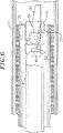
図1は延びていない位置にある本発明のスライド組立体の実施例の端面断面図である。
図2は中間摺動部材のウェブの一部分を切り取った状態にある部分的に延びた位置の図1のスライド組立体の内向き側面図である。
図3は本発明のラッチアームの一実施例の斜視図である。
図4は図3のラッチアームの側面図である。
図5は内側摺動部材と中間摺動部材とのウェブの一部分を切り取った状態にあり且つ係合位置にあるラッチアームを備える図1のスライド組立体の内向き側面図である。
図6は内側摺動部材の一部分を切り取った状態にあり且つ係合解除位置にあるラッチアームを備える図1のスライド組立体の内向き側面図である。
図7は本発明のラッチアームの第一の別の実施例の側面立面図である。
図8は本発明のラッチアームの第二の別の実施例の側面立面図である。
発明を実施するための最良の形態
図1を参照すると外側摺動部材11は概してC字形の横断面を有する。また外側摺動部材11は基本部材、固定部材またはキャビネット摺動部材のように複数の名称で呼ばれる。この外側摺動部材11は一対のボールベアリング軌道、すなわち下向きの上方軌道13と上向きの下方軌道15とを有する。これら軌道は鉛直方向内向きの一対の軌道であると言うこともできるが、如何なる向きにもスライド組立体を設置できるので、ここでの鉛直方向は参考としてのみ用いるものである。上方軌道13および下方軌道15は、外側摺動部材11の頂部および底部に形成され、ほぼ平坦な鉛直方向に延びるウェブ17により支持され、このウェブ17はキャビネットまたはラックに固定される摺動部材の外向きの側面を形成する。またウェブ17はほぼ平坦である必要はなく、上方軌道13と下方軌道15とを連結する様々な構成を用いることができる。
中間摺動部材26は概して鉛直方向に延びるウェブ27と、このウェブ27のそれぞれ上部および下部から垂直に延びる概して水平なアーム12、14とを具備する。アーム12の頂面は外向きの軌道23を形成し、アーム12の底面は内向きの軌道29を形成する。アーム14の底面は外向きの軌道25を形成し、アーム14の頂面は内向きの軌道31を構成する。中間摺動部材26のウェブ27は外側摺動部材11のウェブ17の内側に部品を取り付ける空間または該内側から部品を突出させる空間ができるようにするために実質的に平坦ではない。
外側摺動部材11の上方軌道13および下方軌道15内にそれぞれ第一の複数の上方ベアリング19および下方ベアリング21が配置され且つ係合せしめられる。これら上方ベアリング19および下方ベアリング21は同様に中間摺動部材26の外向きの軌道23および25と係合する。上方ボールベアリング19および下方ボールベアリング21を用いて中間摺動部材26に外側摺動部材11を連結することによりこれら摺動部材11、26は摺動可能に連結される。引出しスライド組立体を摺動可能に連結するための機構は公知であり、これら機構の多数の変更例は当業者には明らかである。
中間摺動部材26の鉛直方向内向きの軌道29および31内には複数の上方ベアリング33および下方ベアリング35がそれぞれ配置され且つ係合せしめられる。これら上方ベアリング33および下方ベアリング35はそれぞれほぼC字形の内側摺動部材41の鉛直方向外向きの上方軌道37および下方軌道39と接触する。内側摺動部材41の上方軌道37および下方軌道39はほぼ平坦な鉛直方向に延びるウェブ43により支持され、このウェブ43はスライド組立体の内向きの側面または内側面を形成する。
図2を参照するとラッチアーム51が中間摺動部材26により保持される。ラッチアーム51は中間摺動部材のウェブ27の中央部内に延びるショルダリベット53を用いて中間摺動部材26に回転可能に取り付けられる。なお中間摺動部材26にラッチアーム51を回転可能に取り付けるには数多くの方法を用いることができ、例えば弾性保持用の棘を備え且つラッチアームから突出する円筒形の突起を用いたりまたはショルダリベット53の代りに半管状のリベットを備える中間摺動部材上の押出支柱を用いたりすることができる。
図3に示したようにラッチアーム51はほぼ平坦な鉛直本体55を備える一体的に形成された構造物である。鉛直本体55を通って垂直に枢動孔57が延び、この枢動孔57は中間摺動部材26にラッチアーム51を回転可能に取り付けるためにリベットを受容する。バネ部分とも呼ばれるバネアーム63が鉛直本体55の下方前方縁部と呼ばれる部分から延びており、ここで下方および前方という語は参照するためにのみ用いるものである。バネアーム63が鉛直本体55から上を向いた弓形のように前方へと延びる。ただしバネアーム63は線形の弓形を形成しない。バネアーム63のほぼ中央点には第一の湾曲部64と第二の湾曲部66とがあり、これら湾曲部はバネアーム63の弓形を鉛直本体55の平面に平行な平面に移す(オフセットさせる)。弓形の同一平面上での平行移動(オフセット)は後述する理由によるものである。
バネアーム63の端部には丸くなった前面67および後面69を有する拡大された円筒形の部分65があり、この拡大された円筒形の部分65の軸線方向の寸法は鉛直本体55の厚みよりも厚い。前面67は枢動孔57またはその軸線から最も遠いバネアームの表面を形成する。鉛直本体55と一体に片持ちの突出部分59が形成され、この突出部分59は鉛直本体の上方後方部分に対して垂直または横方向に延びる。また突出部分59はほぼ水平に向けられた上面60と、該上面60から垂直に延びる側面62a、62bと、これら側面62a、62bの間に延びる底面68(図4にシルエットで示した)とを具備する。鉛直本体55の下方後方部分からはほぼV字形の突出部分61が延びる。このV字形の突出部分61はV字の先端が後方に向かって延びるように配置される。またV字形の突出部分61は三つの面61a〜61cを有し、そのうちの一つはストッパ面61aである。ストッパ面61aは鉛直本体55の後縁部と鈍角を成す。中間面61bは鋭角を成してストッパ面61aに接続され、V字形の突出部分61の頂点を形成する。遷移面61cは中間面61bを鉛直本体55の下縁部に接続しており、両接続(すなわち、遷移面61cと中間面61bとの接続及び遷移面61cと鉛直本体55の下縁部との接続)は共に鈍角を成している。
再び図2を参照すると中間摺動部材26のウェブ27に開口73が形成されており、この開口73はラッチアーム51と対面する縁部面75を生成する。なお必ずしも中間摺動部材26に開口を形成することにより縁部面75を生成する必要はない。中間摺動部材26から突出部分または別の当接面を突出させてもよいし、中間摺動部材26に剛性要素を取り付けてもよい。縁部面75およびラッチアーム51はバネアーム63の前面67が縁部面75と接触した状態で中間摺動部材26上に配置される。縁部面75は鉛直本体55と同一平面にはなく、これがバネアーム63に湾曲部64、66が設けられている理由である。別の実施例では縁部面75はバネアーム63のオフセットが必要でなくなるように充分な距離だけ鉛直本体55の平面に突出する。
図2において反時計回り方向にラッチアーム51を回転または揺動させるとバネアーム63が圧縮せしめられる。ラッチアーム51を回転するとバネアーム63の前面67が縁部面75に押しつけられ、これによりバネアーム63が直線的に動くのでバネアーム63の圧縮が生じ、一方、縁部面75がない場合には円筒形の部分65は半径が縁部面75を超えて延びる円弧を描く。このことを念頭におくと、バネアーム63および縁部面75の形状および形態は、ラッチアームの回転によりバネアーム63が圧縮されさえすれば様々な形状および形態でよい。同様に、付勢された位置または係合可能な位置にラッチアームを維持するためにバネアームの圧縮を使用する代りに、付勢された位置にラッチアームを維持するように反対方向に作用するバネアームまたは他のバネ手段の張力を使用してもよい。さらにラッチアームを回転させる代わりに、バネアームに圧縮力または張力を生成するための回転と同じ効果が生じるようにラッチアームを平行移動させてもよい。
内側摺動部材41のC字形断面の下部にボス77(図5に示した)が設けられ、該ボス77はラッチアーム51のV字形の突出部分61のロック用要素として作用する。このボス77はラッチアーム51が付勢位置にある時にラッチアーム51のV字形の突出部分61と接触するのに充分な寸法でなくてはならないが、これについては後述する。ボス77の目的はラッチアーム51のV字形の突出部分61と接触することにあるのでボス77以外の構造を使用してもよい。例えば、ボス77の代りに内側摺動部材41に剛性または半剛性材料のブロックを取り付けてもよい。
中間摺動部材26のウェブ27には切欠き71が形成される。この切欠き71はラッチアーム51の突出部分59が切欠き71を通って延びるように配置される。切欠き71の代りに開口またはスロットを使用してもよい。切欠き71の寸法はバネアーム63が前方または反時計回り方向に回転し、最大限まで圧縮される前にラッチアーム51の突出部分59が切欠き71の縁部に接触するような寸法である。バネアーム63がこの点を超えて移動できてしまうとバネアーム63の圧縮力がバネアーム63を係合可能な位置から離れさせ、ラッチ機構が作動不能とするような過剰回転が発生する。
起動用の傾斜部材(起動要素)91が外側摺動部材11のウェブ17から延びる。この傾斜部材91はラッチアーム51の突出部分59の下側と係合可能な傾斜した上面93を有する。外側摺動部材11に対して中間摺動部材26を伸ばすことによりラッチアーム51の突出部分59が傾斜部材91と接触する。この接触によりバネアーム63により生成された反対方向に向かう圧縮力に勝り、ラッチアーム51のV字形の突出部分61が上述した鉛直方向に概して移動する。次にラッチアーム51が反時計回り方向に回転せしめられ、したがってV字形の突出部分61がもち上げられる。中間摺動部材26が外側摺動部材11に対して上記接触地点を通り過ぎて延びると、ラッチアーム51の突出部分59は傾斜面93のすぐ前方に設けられた傾斜部材91の水平上面95上に載置される。
シーケンスラッチの作動は図5および図6を参照するとさらに理解できる。図5は部分的に伸ばされた位置にあるスライド組立体を示している。内側摺動部材41および中間摺動部材26は外側摺動部材11から僅かに伸ばされている。内側摺動部材41はロック用要素として作用するボス77とラッチアーム51との係合により中間摺動部材26に対して走行または移動が制限されている。特にラッチアーム51のV字形の突出部分61は、ラッチアーム51が付勢された位置にあるのでボス77の経路を妨害する。ラッチアーム51は中間摺動部材26の開口73の縁部面75とバネアーム63の前面67との間の接触により付勢位置に維持される。さらにボス77は、V字形の突出部分61のストッパ面61aにボス77が当接しているので係合位置から外れるようにラッチアーム51を回転させることはできない。
V字形の突出部分61はラッチアーム51が係合位置にある時にボス77がV字形の突出部分61の中間面61bに当接するように配置できる。通常、バネアーム63はこのようなV字形の突出部分61を用いてラッチアーム51を係合または付勢位置に維持する。しかしながら例えばボールベアリングの移動に起因して突出部分59が外側摺動部材11の傾斜部材91に達するのに充分なほど中間摺動部材を伸ばせない場合には、中間摺動部材26から内側摺動部材41を強制的に展開させることによりボス77が中間面61bに対して付加的な力を及ぼし、したがってラッチアーム51が枢動させられ、ラッチの作動が可能となる。
ラッチアーム51の突出部分59が外側摺動部材の起動用傾斜部材91と接触するように中間摺動部材26が移動させられた時点でラッチアーム51は反時計回りの枢動を受ける。起動用傾斜部材91は中間摺動部材26が伸ばされるにつれて突出部分59の経路を妨害する。突出部分59と起動用傾斜部材91との間の接触はバネアーム63と縁部面75との間の接触により生成される圧縮力よりも大きく反対方向に導かれた成分を伴う引張力を生成する。したがって突出部分59と起動用傾斜部材91との間の接触はラッチアーム51を付勢位置、すなわち係合位置から外れるように枢動させる。さらに突出部分59と起動用傾斜部材91との間の接触は摩擦界面を生成するのにも使用可能であり、これにより更なる伸長のためにラッチアーム51を枢動せしめて内側摺動部材41を解放するのに充分な程度に中間摺動部材26を伸長させるのに付加的な力が必要になる。摩擦界面における摩擦力に打ち勝つのに必要な力の大きさはバネアーム63の強度および圧縮に応じて変化する。
枢動の結果は図6に見られる。図6では中間摺動部材26は、外側摺動部材11に対して、突出部分59が起動用傾斜部材91の上面に載置された位置に到達している。バネアーム63は中間摺動部材26の開口73の縁部面75と圧縮接触状態にある。さらにラッチアーム51のV字形の突出部分61はそれが内側摺動部材41のボス77と係合可能でない位置まで枢動させられている。したがって中間摺動部材26に対する内側摺動部材41の運動は制限されていない。
図6に示したようにボス77はラッチアーム51が付勢位置にない時にはV字形の突出部分61とは接触しない。しかしながらこれは必要条件ではない。ラッチアームは、係合解除位置にある時にボス77とラッチアーム51との間に接触が生じ、この接触点がV字形の突出部分61の遷移面61c上にくるように、鉛直方向に配置されてもよい。遷移面上での接触はラッチアーム51を係合位置からさらに枢動させる力をラッチアーム51に誘発し、これによりボス77がラッチアーム51を通過できるようにする。このような状況では、ボス77とV字形の突出部分61との間の接触はスライド組立体の収縮の際の摩擦界面を生成する。スライド組立体を伸ばす際の摩擦界面を生成するために同様に中間面61bを使用することもできる。さらにV字形の突出部分61およびボス77について様々な形状を用いることでラッチアーム51の枢動を誘発する力の成分を異なるものとすることができ、これによりスライド組立体を伸長させる際または収縮させる際の摩擦界面における摩擦力に打ち勝つのに必要な力の大きさを異ならせることができる。
ラッチアームの変形例を図7に示した。この図に示したようにラッチアーム110はほぼ平坦な鉛直本体111を有する。ラッチアームを中間摺動部材に並進運動できるように取り付けるためにリベットまたはその他の機構を収容するように鉛直本体111を通って垂直方向にスロット113が延びる。鉛直本体111と同一平面上において鉛直本体111から上方へと多数のバネアーム115、117が延びる。これらバネアーム115、117の端部には円筒形の部分125、177が設けられる。突出部分119(シルエットで示した)が鉛直本体111に連結され、鉛直本体111に対して垂直または横方向に突出する。また突出部分119は実質的に水平方向を向いた上面と、この上面から垂直に延びる側面114、118と、側面に連結された底面122とを有する。鉛直本体111の底面から突出するのはほぼV字形の突出部分121であり、V字の先端は後ろ向き方向にオフセットされている。
スライド組立体内での本実施形態のラッチアームの作動には前述した実施形態において利用されたものに類似した原理が利用される。バネアーム115、117の圧縮はV字形の突出部分121がボス77(図5に示した)と係合可能となる位置へとラッチアーム110を付勢させる。この圧縮は中間摺動部材の縁部、突起またはその他の異形部分と円筒形形材125、127との接触により引き起こされる。外側摺動部材上の起動用傾斜部材91(図2に示した)と突出部分119との相互作用は突出部分119と起動用傾斜部材91の間の接触がラッチアームを枢動させず、その代りに鉛直方向に並進運動させるという点を除いて実質的に上述と同様である。この鉛直方向への並進運動はV字形の突出部分121をボス77の経路から外れるように持ち上げさせる。
ラッチアームの別の変更実施形態を図8に示した。このラッチアームは上述した図3のラッチアームと類似の様相を共有するがバネの作動に関して異なる。ラッチアーム130は鉛直本体151を有し、この鉛直本体の上方前方部分からバネアーム163が延びる。バネアーム163は概してV字形であり、鉛直本体151と同一平面上にあり、取付け端部134は鉛直本体151から延び、自由端部132は取付け端部134の遠い部分から鉛直本体151に向かって戻る。バネアーム163は内面164を有する。内面164は中間摺動部材26から延びるタブ(図示せず)と接触するように適合されたバネアーム163の第一領域165と第二領域167とを具備する。ラッチアーム130が付勢位置にある時にはタブは第一領域165と接触状態にある。付勢位置から外れるようにラッチアームを枢動させることにより第二領域167がタブと接触せしめられ、これによりバネアーム163の取付け端部134から離れるようにアーム163の自由端部132を付勢することによりバネアーム163を開く引張り力を誘発する。したがってこの引張り力はラッチアーム130を図2のボス77といったようなロック用要素と係合可能な位置にとどまらせる傾向を有する。
本発明について特定の実施形態を説明したが当業者には多数の別の修正および変更が明らかである。したがって本発明は特別に説明したもの以外の形で実施可能である。例えばロック用要素は内側摺動部材の概してC字形断面の下縁部上に配置されたボスに代って内側摺動部材の鉛直方向に延びるウェブから延びる突起でもよい。さらにラッチアームの一部分またはバネアームは一体構造のラッチアームの一部を構成する必要はなく、ラッチアームを係合位置に付勢させる任意のバネ機構でもよい。したがって本発明の当該実施形態はあらゆる点において制限的な意味のない例示を目的とするものであり、本発明の範囲は上記の記載ではなく添付の請求の範囲により示されるものである。Technical field
The present invention is a ball bearing. formula slide Assembly Relates to a sequence latch for In particular, the present invention provides a third Sliding Two for the member Sliding The parts are ordered so that the parts move preferentially Sliding Nested slide with members Assembly About.
Background art
Nested slide for file drawer Assembly Is often desirable for use in cabinets and other applications such as rack mounting. This slide Assembly Can easily access the inside of the drawer. Also slide Assembly Maintains the drawer in a horizontal position regardless of the distance the drawer is withdrawn from the cabinet. Standard drawer formula slide Assembly Has three sliding members, which are slidably fixed to each other by a pair of ball bearings, and the ball bearings are held by a cage mounted on a track formed on these sliding members. The
Usually a three-element telescopic slide Assembly Comprises an outer sliding member, an intermediate sliding member, and an inner sliding member. In the description, the outer sliding member is connected to the cabinet or the surrounding member. However, the inner sliding member may be connected to the cabinet or the surrounding member. The sliding member attached to the drawer when the outer sliding member is connected to the cabinet or enclosure member is the inner sliding member. The intermediate sliding member is slidably connected to both the outer sliding member and the inner sliding member. In this configuration, when the drawer is in the fully open position, the intermediate sliding member is against the outer sliding member. Extension The inner sliding member against the intermediate sliding member Extension It is arranged to jump.
This basic slide Assembly Then the intermediate sliding member is against the outer sliding member Extension And the inner sliding member against the intermediate sliding member Extension The order of jumping is not necessarily predetermined. Considering the strength and smoothness of operation, a predetermined slide Assembly In a given order or sequence in the configuration To operate Is preferred. Operates external mechanisms such as cabinet interlocks Make Requires a specific operating sequence. In addition, the standard drawer is supported by two slide assemblies, one on each side. Of both slide assemblies Sliding In the same order Extension It is desirable to jump. The two slide assemblies in the same order Extension Slide if not Assembly The load bearing capacity of the is reduced.
Slide assemblies that provide ordering motion are disclosed in US Pat. No. 4,537,450 to Alan R. Baxter or US Pat. No. 5,181,782 to Thadeus H. Wojcik. Disclosed slide Assembly The ordering mechanism is dependent on the interaction of at least one elastic latch member. The weakness of this design is the loss of elasticity of the elastic latch member. Another problem with using elastic latching components is that due to their nature, strict attention must be paid to their dimensions. No ordering occurs if the size of the elastic latch member is insufficient. If the size of the elastic latch member is too large, the elastic latch member is fixed to the latch mechanism and slides. Assembly But Extension It will prevent you from falling. For this reason, care must be taken in the manufacturing process not to exceed certain very tight tolerances. In addition, an elastic latch member formed of a material such as polyurethane interacts with grease, oil, or other petroleum-based lubricants. Depending on the material utilized, the elastic latch member may have a tendency to absorb the lubricant, and this absorption causes the elastic latch member to expand in size. This size increase is an ordered drawer slide Assembly It will require more power than usual to release.
Slide using a pivoting latch Assembly Is disclosed in US Pat. No. 5,551,775 of the inventor, the disclosure of which is hereby incorporated by reference. This slide Assembly Uses a single pivoting latch member that does not rely on a resilient member for its operation. However slide Assembly Will cause excessive noise when the pivoting latch member is forced to pivot due to contact with the inner sliding member and when the pivoting latch member reaches its pivot range limit. appear. In addition, the pivoting latch member utilizes gravity to return it to an engageable position. Thus the disclosed latch is a slide Assembly A drawer-type drawer slide that can be mounted horizontally under the drawer Assembly As in the drawer slide Assembly Drawer slide that cannot be installed vertically Assembly The mounting configuration does not perform that function.
Further drawer slide Assembly Movement of the ball bearing renders the latch inoperable. The movement of the ball bearing is when a slight variation in the surface of the track on which the ball bearing rests causes a temporary loss of contact between the ball bearing and the track or a slight obstacle in the movement of the ball bearing along the track. Arise. These slides are slidably connected drawer slides while cyclical work is repeated Assembly Will change the position of the ball bearing cage with respect to. Slide with ball bearing cage Assembly The linked slides are part of a stop mechanism that prevents them from unfolding from each other, or as a result of this relative position change when interacting with this stop mechanism. Assembly Cannot reach its maximum relative extension in its design. When this happens, the latch member of U.S. Pat.No. 5,551,775 will allow the latch member to extend further slidably if there is not enough force to deform or shear a portion of the engaged latch member. Hinder.
An initial state return stopper can be used to reposition the ball bearing cage to its original design position or to return to the initial state, but the initial state return stopper is a force to reposition the cage. Depending on whether the drawer is fully opened and closed. In normal use, the drawer is not fully extended regularly when opened, or is extended with insufficient force to return the ball bearing retainer to its initial position. For this reason, the use of an initial state return stopper does not provide a perfect solution to the disadvantage that movement of the ball bearing adversely affects the operation of the latch.
Disclosure of the invention
The present invention relates to a telescopic slide having an outer sliding member, an intermediate sliding member, and an inner sliding member. Assembly Provides an ordering mechanism for The sequencing mechanism includes a latch arm supported by the intermediate sliding member, a locking element on the inner sliding member, and an activation element on the outer sliding member. The latch arm is a spring arm that contacts the intermediate sliding member to maintain or bias the latch arm in a normally biased or engageable position relative to the locking element on the inner sliding member. The compression force of the spring arm formed integrally with the latch arm is used. The actuating element, which is a ramp projecting from the outer sliding member, interacts with the projecting portion of the latch arm to overcome the biasing force generated by the compression of the spring arm, thereby disengaging the latch arm from an engageable position. The inner sliding member can run freely.
By providing a rotatable latch arm to provide sliding member ordering, the present invention avoids the need for very specific and tight tolerances of the elastic latch member. The attendant problems of oil-based lubricant absorption and the resulting latch member size change are likewise avoided. The use of a spring arm to maintain the latch arm in the biased position reduces the noise associated with the operation of the latch. Since the operation of the latch is not weight dependent, the spring arm also allows the slide assembly to be mounted in any orientation. Furthermore, the present invention provides a sliding slide without the need for permanent deformation of the latch arm even when ball bearing movement occurs. Assembly Enabling the operation of
[Brief description of the drawings]
The details of the invention are described below and will be better understood with reference to the following drawings.
FIG. 1 shows the slide of the present invention in an unextended position. Assembly It is end surface sectional drawing of the Example of.
2 shows the slide of FIG. 1 in a partially extended position with a portion of the web of the intermediate sliding member cut away. Assembly FIG.
FIG. 3 is a perspective view of an embodiment of the latch arm of the present invention.
4 is a side view of the latch arm of FIG.
FIG. 5 shows the slide of FIG. 1 with the latch arm in the engaged position, with a portion of the web of the inner and intermediate sliding members cut away. Assembly FIG.
6 shows the slide of FIG. 1 with the latch arm in a disengaged position with a portion of the inner sliding member cut away. Assembly FIG.
FIG. 7 is a side elevational view of a first alternative embodiment of the latch arm of the present invention.
FIG. 8 is a side elevational view of a second alternative embodiment of the latch arm of the present invention.
BEST MODE FOR CARRYING OUT THE INVENTION
Referring to FIG. 1, the outer sliding
Middle Sliding The
A first plurality of
A plurality of
Referring to FIG. 2, the
As shown in FIG. 3, the
At the end of the
Referring again to FIG. 2, an
In FIG. 2, when the
A boss 77 (shown in FIG. 5) is provided at the bottom of the C-shaped cross section of the inner sliding
A
Inclined member for starting (Launch element) 91 extends from the
The operation of the sequence latch can be further understood with reference to FIGS. Figure 5 partially Stretched Slide in position Assembly Is shown. The inner sliding
When the
When the intermediate sliding
The result of the pivoting can be seen in FIG. In FIG. 6, the intermediate sliding
As shown in FIG. 6, the
A modification of the latch arm is shown in FIG. As shown in this figure, the latch arm 110 is Almost It has a flat
The operation of the latch arm of the present embodiment within the slide assembly employs principles similar to those utilized in the previously described embodiments. The compression of the
Another alternative embodiment of the latch arm is shown in FIG. This latch arm shares a similar aspect to the latch arm of FIG. 3 described above, but differs with respect to the operation of the spring. The
While particular embodiments of the present invention have been described, numerous other modifications and changes will be apparent to those skilled in the art. Accordingly, the present invention may be practiced other than as specifically described. For example, the locking element may be a protrusion extending from a vertically extending web of the inner sliding member in place of a boss disposed on the lower edge of the inner sliding member in a generally C-shaped cross section. In addition, part of the latch arm or spring arm Togetherness It is not necessary to constitute a part of the latch arm of the structure, and any spring mechanism that biases the latch arm to the engagement position may be used. Accordingly, the embodiments of the present invention are intended to be illustrative in all respects and not restrictive, and the scope of the present invention is defined by the appended claims rather than the foregoing description.
Claims (7)
該内側摺動部材に摺動可能に連結される中間摺動部材(26)と、
該中間摺動部材に摺動可能に連結される外側摺動部材(11)と、
前記中間摺動部材により支持されるラッチアーム(51)と、
前記内側摺動部材と中間摺動部材とが互いに第一の予め定められた位置にある時に前記ラッチアームに係合する前記内側摺動部材上のロック要素(77)と、
通常は前記ラッチアームを係合可能な位置に付勢する前記中間摺動部材の一部分と係合状態にあるバネ手段(63)と、
前記外側摺動部材と中間摺動部材が互いに第二の予め定められた位置にある時に前記バネ手段に対抗して作用してラッチアームを係合可能な位置から外れるように付勢する前記外側摺動部材上の起動要素(91)とを具備するスライド組立体。An inner sliding member (41) ;
An intermediate sliding member (26) slidably coupled to the inner sliding member;
An outer sliding member (11) slidably coupled to the intermediate sliding member;
A latch arm (51) supported by the intermediate sliding member;
A locking element (77) on the inner sliding member that engages the latch arm when the inner sliding member and the intermediate sliding member are in a first predetermined position relative to each other;
Spring means (63) in engagement with a portion of the intermediate sliding member that normally biases the latch arm to an engageable position;
The outer sliding member and the intermediate sliding member acting against the spring means to bias the latch arm away from the engageable position when the outer sliding member and the intermediate sliding member are in a second predetermined position with respect to each other; A slide assembly comprising an activation element (91) on the sliding member.
Applications Claiming Priority (3)
| Application Number | Priority Date | Filing Date | Title |
|---|---|---|---|
| US08/796,055 US5757109A (en) | 1997-02-07 | 1997-02-07 | Telescopic drawer slide with soft sequencing latch |
| US08/796,055 | 1997-02-07 | ||
| PCT/US1998/002353 WO1998034516A1 (en) | 1997-02-07 | 1998-02-06 | Telescopic drawer slide with soft sequencing latch |
Publications (3)
| Publication Number | Publication Date |
|---|---|
| JP2001511046A JP2001511046A (en) | 2001-08-07 |
| JP2001511046A5 JP2001511046A5 (en) | 2005-09-08 |
| JP4308914B2 true JP4308914B2 (en) | 2009-08-05 |
Family
ID=25167157
Family Applications (1)
| Application Number | Title | Priority Date | Filing Date |
|---|---|---|---|
| JP53492998A Expired - Lifetime JP4308914B2 (en) | 1997-02-07 | 1998-02-06 | Slide assembly |
Country Status (6)
| Country | Link |
|---|---|
| US (1) | US5757109A (en) |
| EP (1) | EP0973422B1 (en) |
| JP (1) | JP4308914B2 (en) |
| CA (1) | CA2280886C (en) |
| DE (1) | DE69824955T2 (en) |
| WO (1) | WO1998034516A1 (en) |
Families Citing this family (59)
| Publication number | Priority date | Publication date | Assignee | Title |
|---|---|---|---|---|
| US5961193A (en) * | 1997-11-07 | 1999-10-05 | General Devices Co., Inc. | Release-control mechanism for telescoping slide assembly |
| NL1010136C2 (en) | 1998-09-21 | 2000-03-22 | Thomas Regout B V | Disco-locking. |
| US6497464B1 (en) | 1999-06-22 | 2002-12-24 | Accuride International, Inc. | Adjustable detent mechanism for drawer slide |
| US6435636B1 (en) | 2000-06-15 | 2002-08-20 | Compx International Inc. | Drawer slide cushion end stop bumper construction |
| US6224177B1 (en) * | 2000-08-22 | 2001-05-01 | Yin Da Slide Co., Ltd. | Sliding track assembly |
| US6685288B1 (en) | 2000-10-16 | 2004-02-03 | Compx International Inc. | Drawer slide with sequence control mechanism |
| US6454372B1 (en) * | 2000-11-16 | 2002-09-24 | Jun-Long Yang | Positioning device for a drawer rail |
| US6655763B2 (en) | 2000-12-22 | 2003-12-02 | Jonathan Engineered Solutions | Controller for a quick disconnect slide assembly |
| US6554379B2 (en) | 2001-02-16 | 2003-04-29 | Central Industrial Supply Company, Inc. | Slide rail assembly with front release |
| US6350001B1 (en) * | 2001-05-08 | 2002-02-26 | Dynaslide Corporation | Sliding track assembly for drawer |
| US6450600B1 (en) * | 2001-08-03 | 2002-09-17 | King Slide Works Co., Ltd. | Retaining structure for a track device for preventing inadvertent inward movement |
| US6938967B2 (en) * | 2001-12-12 | 2005-09-06 | Pentair Electronic Packaging Co. | Telescoping slide assembly |
| US6883885B2 (en) | 2001-12-19 | 2005-04-26 | Jonathan Manufacturing Corporation | Front release for a slide assembly |
| US6764149B2 (en) | 2002-04-23 | 2004-07-20 | Compx International Inc. | Drawer slide assembly locking and release mechanism |
| US7029080B2 (en) | 2002-09-25 | 2006-04-18 | Central Industrial Supply Company | Slide rail having front release latch |
| DE20219283U1 (en) * | 2002-12-12 | 2003-02-20 | Dynaslide Corp Tan Shui Cheng | Self-locking device of a slide rail arrangement for a drawer |
| US7364245B2 (en) * | 2002-12-18 | 2008-04-29 | Pentair Electronic Packaging Company | Lateral alignment device |
| US6923518B2 (en) * | 2003-01-27 | 2005-08-02 | Accuride International Inc. | Drawer slide and drawer slide adjustment mechanism |
| GB2400785B (en) * | 2003-04-11 | 2005-10-19 | King Slide Works Co Ltd | Safety device for a slide track retainer |
| WO2004107912A2 (en) * | 2003-05-30 | 2004-12-16 | Central Industrial Supply Company (A Texas Corporation) | Cam lock with torsion spring for a drawer slide |
| US20050017613A1 (en) * | 2003-06-23 | 2005-01-27 | Paul Cirocco | Front-release lock arrangement for slide assembly |
| US7404611B1 (en) * | 2003-07-09 | 2008-07-29 | Central Industrial Supply Company | Pin and torsion spring lock for a drawer slide |
| CN100515540C (en) * | 2003-12-19 | 2009-07-22 | 新东工业株式会社 | Filter element for dust collector |
| GB0329553D0 (en) * | 2003-12-22 | 2004-01-28 | Widney Uk Ltd | Telescopic slide apparatus |
| US7108340B2 (en) * | 2004-06-08 | 2006-09-19 | Hsing Lyiang Industry Co., Ltd. | Rail assembly for a drawer |
| CN100443015C (en) * | 2004-07-23 | 2008-12-17 | 川湖科技股份有限公司 | Sliding synchronous device for three-section type sliding rail |
| US7413269B2 (en) * | 2004-08-04 | 2008-08-19 | King Slide Works Co., Ltd. | Synchronous system for a three-stage ball bearing slide |
| GB2416670B (en) * | 2004-08-05 | 2006-06-21 | King Slide Works Co Ltd | Synchronous system for a three-stage ball bearing slide |
| US7118277B2 (en) * | 2004-12-08 | 2006-10-10 | King Slide Works Co., Ltd. | Slide assembly |
| US6997529B1 (en) | 2005-01-19 | 2006-02-14 | King Slide Works Co., Ltd. | Synchronizing device for a tri-sector slide |
| TWI261509B (en) * | 2005-06-24 | 2006-09-11 | King Slide Works Co Ltd | Positioning device for a tri-sector slide |
| US7533946B2 (en) * | 2005-08-25 | 2009-05-19 | Knape & Vogt Manufacturing Company | Closing device for drawers |
| US7357468B2 (en) * | 2006-01-19 | 2008-04-15 | King Slide Works Co., Ltd. | Locating structure for a slide assembly |
| US20080012456A1 (en) * | 2006-06-06 | 2008-01-17 | Judge Ronald J | Server cabinet with slide assembly |
| US7458651B1 (en) * | 2006-11-08 | 2008-12-02 | Atc Hardware Systems, Inc. | Drawer slide with adjustable strike |
| CN100561001C (en) * | 2006-12-01 | 2009-11-18 | 鸿富锦精密工业(深圳)有限公司 | Ball slide rail |
| US7780252B2 (en) * | 2007-02-16 | 2010-08-24 | Central Industrial Supply Company | Elongated staging lock for a drawer slide |
| US7611213B2 (en) | 2007-03-13 | 2009-11-03 | Atom International Co., Ltd. | Sliding track assembly |
| US7708357B2 (en) * | 2007-03-20 | 2010-05-04 | Weon-Dong Cho | Automatic locking apparatus used in guide rail for drawer |
| US8434836B2 (en) * | 2007-08-30 | 2013-05-07 | Waterloo Industries, Inc. | Slide assembly |
| DE202009001962U1 (en) * | 2008-11-03 | 2010-04-01 | Paul Hettich Gmbh & Co. Kg | pull-out guide |
| DE102010016594A1 (en) * | 2010-04-22 | 2011-10-27 | Paul Hettich Gmbh & Co. Kg | Pull-out guide for furniture or household appliances |
| CN102238841A (en) * | 2010-04-27 | 2011-11-09 | 鸿富锦精密工业(深圳)有限公司 | Slide rail mechanism |
| US8317278B2 (en) | 2010-08-18 | 2012-11-27 | Knape & Vogt Manufacturing Company | Releasably locking slide assemblies |
| US8439459B2 (en) * | 2010-11-29 | 2013-05-14 | Lockheed Martin Corporation | Apparatus for latching a drawer using a cam latch |
| US8876230B2 (en) | 2011-09-24 | 2014-11-04 | Hardware Resources, Inc. | Durable drawer retainer apparatus and method of use |
| US9750347B2 (en) | 2012-04-30 | 2017-09-05 | Hardware Resources, Inc. | Pressure release slide latch mechanism |
| US9648952B2 (en) | 2012-04-30 | 2017-05-16 | Hardware Resources, Inc. | Pressure release slide latch mechanism |
| DE102013102944A1 (en) | 2012-10-12 | 2014-06-18 | Paul Hettich Gmbh & Co. Kg | pull-out guide |
| KR20150081744A (en) * | 2014-01-06 | 2015-07-15 | 삼성전자주식회사 | Dish washer |
| JP5725219B1 (en) * | 2014-01-29 | 2015-05-27 | 日本電気株式会社 | Slide rail unit |
| US10117352B2 (en) * | 2016-01-06 | 2018-10-30 | King Slide Works Co., Ltd. | Slide rail assembly |
| TWM559116U (en) * | 2017-06-13 | 2018-05-01 | 信錦企業股份有限公司 | Slide module |
| TWI638624B (en) | 2017-06-23 | 2018-10-21 | 川湖科技股份有限公司 | Slide rail assembly |
| CN109124109B (en) * | 2017-06-28 | 2021-08-10 | 川湖科技股份有限公司 | Sliding rail assembly |
| US10463149B1 (en) * | 2018-11-22 | 2019-11-05 | Martas Precision Slide Co., Ltd. | Steel ball slot locking mechanism of slide rail |
| WO2020242393A1 (en) * | 2019-05-27 | 2020-12-03 | Samet Kalip Ve Madeni̇ Eşya San Ti̇c. A.Ş | Ball rail system for drawers |
| TWI704888B (en) * | 2019-07-12 | 2020-09-21 | 川湖科技股份有限公司 | Slide rail assembly |
| TWI705204B (en) | 2019-10-01 | 2020-09-21 | 川湖科技股份有限公司 | Slide rail assembly and slide rail kit thereof |
Family Cites Families (25)
| Publication number | Priority date | Publication date | Assignee | Title |
|---|---|---|---|---|
| US1582556A (en) * | 1921-01-31 | 1926-04-27 | Roneo Ltd | Drawer guide |
| US1963220A (en) * | 1934-02-09 | 1934-06-19 | Gen Fireproofing Co | Drawer suspension |
| US2606090A (en) * | 1948-10-18 | 1952-08-05 | Gen Fireproofing Co | Drawer suspension |
| US2655422A (en) * | 1951-04-24 | 1953-10-13 | Grant Pulley & Hardware Corp | Pivotally movable sliding bracket for drawers or shelves and locking means therefor |
| US3488097A (en) * | 1968-07-26 | 1970-01-06 | Herbert S Fall | Heavy-duty drawer slide |
| US3912341A (en) * | 1973-10-23 | 1975-10-14 | Hardware Designers Inc | Progressive drawer slide |
| DE2721231A1 (en) * | 1977-05-11 | 1978-11-16 | Schock & Co Gmbh | DOUBLE PULL-OUT DEVICE FOR LINEAR GUIDANCE OF A MOVABLE PART, FOR EXAMPLE A DRAWER |
| US4272139A (en) * | 1978-09-12 | 1981-06-09 | Jacmorr Manufacturing Limited | Sliding drawer suspension |
| US4370007A (en) * | 1979-02-08 | 1983-01-25 | Jacmorr Manufacturing Limited | Sliding drawer suspension |
| DE3026544A1 (en) * | 1979-07-19 | 1981-02-05 | Blum Gmbh Julius | EXTENSION GUIDE SET FOR DRAWERS OR THE LIKE |
| CA1125346A (en) * | 1979-11-07 | 1982-06-08 | Jack P. Fler | Three part slide |
| US4560212A (en) * | 1983-10-07 | 1985-12-24 | Standard Precision, Inc. | Three part ball bearing slide with lockable intermediate slide member |
| US4549773A (en) * | 1983-10-07 | 1985-10-29 | Standard Precision, Inc. | Ball bearing slide with removable and lockable inner slide member |
| US4563044A (en) * | 1985-03-08 | 1986-01-07 | General Motors Corporation | Latching arrangement for seat slide structures |
| US4610487A (en) * | 1985-09-16 | 1986-09-09 | Standard Precision, Inc. | Drawer slide with lock |
| US4988214A (en) * | 1986-08-18 | 1991-01-29 | Knape & Vogt Manufacturing Co. | Sequential drawer slide |
| US4662761A (en) * | 1986-08-18 | 1987-05-05 | Knape & Vogt Manufacturing Company | Sequential drawer slide |
| US4696582A (en) * | 1986-10-27 | 1987-09-29 | Standard Precision, Inc. | Three member drawer slide with sequential movement |
| US4749242A (en) * | 1987-06-22 | 1988-06-07 | Robert Rechberg | Drawer slide |
| US4998828A (en) * | 1989-10-02 | 1991-03-12 | General Devices Co., Inc. | Over and under telescoping slide assembly |
| US5033805A (en) * | 1990-05-08 | 1991-07-23 | General Devices Co., Inc. | Drawer slide assembly with releasable lock mechanism |
| NL9001969A (en) * | 1990-09-06 | 1992-04-01 | Regout Nv Thomas | TELESCOPIC RAIL WITH LOCKING MECHANISM. |
| US5316389A (en) * | 1992-08-24 | 1994-05-31 | Knape & Vogt Manufacturing Company | Drawer slide assembly |
| US5417490A (en) * | 1993-03-29 | 1995-05-23 | General Devices Co., Inc. | Telescoping slide assembly |
| US5551775A (en) * | 1994-02-22 | 1996-09-03 | Accuride International, Inc. | Telescopic drawer slide with mechanical sequencing latch |
-
1997
- 1997-02-07 US US08/796,055 patent/US5757109A/en not_active Expired - Lifetime
-
1998
- 1998-02-06 EP EP98907391A patent/EP0973422B1/en not_active Expired - Lifetime
- 1998-02-06 JP JP53492998A patent/JP4308914B2/en not_active Expired - Lifetime
- 1998-02-06 CA CA002280886A patent/CA2280886C/en not_active Expired - Fee Related
- 1998-02-06 WO PCT/US1998/002353 patent/WO1998034516A1/en active IP Right Grant
- 1998-02-06 DE DE69824955T patent/DE69824955T2/en not_active Expired - Fee Related
Also Published As
| Publication number | Publication date |
|---|---|
| EP0973422A4 (en) | 2001-04-25 |
| WO1998034516A1 (en) | 1998-08-13 |
| CA2280886C (en) | 2007-04-17 |
| DE69824955T2 (en) | 2005-07-14 |
| CA2280886A1 (en) | 1998-08-13 |
| MX9907285A (en) | 2002-12-13 |
| US5757109A (en) | 1998-05-26 |
| EP0973422A1 (en) | 2000-01-26 |
| JP2001511046A (en) | 2001-08-07 |
| DE69824955D1 (en) | 2004-08-12 |
| EP0973422B1 (en) | 2004-07-07 |
Similar Documents
| Publication | Publication Date | Title |
|---|---|---|
| JP4308914B2 (en) | Slide assembly | |
| US5207781A (en) | Closing device for moving a drawer to a fully inserted position within a furniture body | |
| CA2620192C (en) | Closing device for drawers | |
| JP4874506B2 (en) | Friction drawer slide | |
| US7537296B2 (en) | Dampened movement mechanism and slide incorporating the same | |
| US5551775A (en) | Telescopic drawer slide with mechanical sequencing latch | |
| US8459758B2 (en) | Drawer slide auto-close dampening system with reset feature | |
| US7708357B2 (en) | Automatic locking apparatus used in guide rail for drawer | |
| CA2345531C (en) | File interlock system and mechanism | |
| US5871265A (en) | Two-way slide | |
| US7448704B2 (en) | Drawer guide rail assembly | |
| WO2007111424A1 (en) | Self closing means | |
| US20060082266A1 (en) | Self-moving slides and self-moving mechanisms | |
| US4735151A (en) | Latch and hinge assembly | |
| US6729703B2 (en) | Snap-in latch | |
| US20090058242A1 (en) | Slide assembly | |
| JP6817626B2 (en) | Sliding door closer | |
| JP4002595B2 (en) | Slide rail | |
| CN108567251B (en) | Return mechanism for movable furniture component | |
| JP5184109B2 (en) | Sliding device for moving side member | |
| MXPA99007285A (en) | Telescopic drawer slide with soft sequencing latch | |
| JP2500806Y2 (en) | Folding leg support bracket | |
| CN108720381B (en) | Clutch for furniture assembly | |
| US20240122342A1 (en) | Slide rail assembly | |
| KR101056917B1 (en) | Automatic closing device with long stroke |
Legal Events
| Date | Code | Title | Description |
|---|---|---|---|
| A521 | Request for written amendment filed |
Free format text: JAPANESE INTERMEDIATE CODE: A523 Effective date: 20050111 |
|
| A621 | Written request for application examination |
Free format text: JAPANESE INTERMEDIATE CODE: A621 Effective date: 20050111 |
|
| A131 | Notification of reasons for refusal |
Free format text: JAPANESE INTERMEDIATE CODE: A131 Effective date: 20080708 |
|
| A521 | Request for written amendment filed |
Free format text: JAPANESE INTERMEDIATE CODE: A523 Effective date: 20081007 |
|
| TRDD | Decision of grant or rejection written | ||
| A01 | Written decision to grant a patent or to grant a registration (utility model) |
Free format text: JAPANESE INTERMEDIATE CODE: A01 Effective date: 20090407 |
|
| A01 | Written decision to grant a patent or to grant a registration (utility model) |
Free format text: JAPANESE INTERMEDIATE CODE: A01 |
|
| A61 | First payment of annual fees (during grant procedure) |
Free format text: JAPANESE INTERMEDIATE CODE: A61 Effective date: 20090507 |
|
| R150 | Certificate of patent or registration of utility model |
Free format text: JAPANESE INTERMEDIATE CODE: R150 |
|
| FPAY | Renewal fee payment (event date is renewal date of database) |
Free format text: PAYMENT UNTIL: 20120515 Year of fee payment: 3 |
|
| FPAY | Renewal fee payment (event date is renewal date of database) |
Free format text: PAYMENT UNTIL: 20120515 Year of fee payment: 3 |
|
| FPAY | Renewal fee payment (event date is renewal date of database) |
Free format text: PAYMENT UNTIL: 20130515 Year of fee payment: 4 |
|
| R250 | Receipt of annual fees |
Free format text: JAPANESE INTERMEDIATE CODE: R250 |
|
| R250 | Receipt of annual fees |
Free format text: JAPANESE INTERMEDIATE CODE: R250 |
|
| R250 | Receipt of annual fees |
Free format text: JAPANESE INTERMEDIATE CODE: R250 |
|
| R250 | Receipt of annual fees |
Free format text: JAPANESE INTERMEDIATE CODE: R250 |
|
| R250 | Receipt of annual fees |
Free format text: JAPANESE INTERMEDIATE CODE: R250 |
|
| EXPY | Cancellation because of completion of term |