JP4307154B2 - Control device for electric power steering device - Google Patents
Control device for electric power steering device Download PDFInfo
- Publication number
- JP4307154B2 JP4307154B2 JP2003147759A JP2003147759A JP4307154B2 JP 4307154 B2 JP4307154 B2 JP 4307154B2 JP 2003147759 A JP2003147759 A JP 2003147759A JP 2003147759 A JP2003147759 A JP 2003147759A JP 4307154 B2 JP4307154 B2 JP 4307154B2
- Authority
- JP
- Japan
- Prior art keywords
- circuit
- electric power
- power steering
- arithmetic circuit
- phase advance
- Prior art date
- Legal status (The legal status is an assumption and is not a legal conclusion. Google has not performed a legal analysis and makes no representation as to the accuracy of the status listed.)
- Expired - Fee Related
Links
Images


Classifications
-
- H—ELECTRICITY
- H02—GENERATION; CONVERSION OR DISTRIBUTION OF ELECTRIC POWER
- H02P—CONTROL OR REGULATION OF ELECTRIC MOTORS, ELECTRIC GENERATORS OR DYNAMO-ELECTRIC CONVERTERS; CONTROLLING TRANSFORMERS, REACTORS OR CHOKE COILS
- H02P6/00—Arrangements for controlling synchronous motors or other dynamo-electric motors using electronic commutation dependent on the rotor position; Electronic commutators therefor
- H02P6/10—Arrangements for controlling torque ripple, e.g. providing reduced torque ripple
-
- B—PERFORMING OPERATIONS; TRANSPORTING
- B62—LAND VEHICLES FOR TRAVELLING OTHERWISE THAN ON RAILS
- B62D—MOTOR VEHICLES; TRAILERS
- B62D5/00—Power-assisted or power-driven steering
- B62D5/04—Power-assisted or power-driven steering electrical, e.g. using an electric servo-motor connected to, or forming part of, the steering gear
- B62D5/0457—Power-assisted or power-driven steering electrical, e.g. using an electric servo-motor connected to, or forming part of, the steering gear characterised by control features of the drive means as such
- B62D5/046—Controlling the motor
- B62D5/0472—Controlling the motor for damping vibrations
Description
【0001】
【発明の属する技術分野】
本発明は、自動車や車両の操舵系にモータによる操舵補助力を付与するようにした電動パワーステアリング装置の制御装置に関し、特に制御装置に入力される信号から制御遅れがなくかつ有効な信号を減衰させることなくノイズだけを除去できるようにした電動パワーステアリング装置の制御装置に関する。
【0002】
【従来の技術】
自動車や車両のステアリング装置をモータの回転力で補助力付勢する電動パワーステアリング装置は、モータの駆動力を減速機を介してギア又はベルト等の伝達機構により、ステアリングシャフト或いはラック軸に操舵補助力を付与するようになっている。かかる従来の電動パワーステアリング装置は、アシストトルク(操舵補助トルク)を正確に発生させるため、ハンドルからのトルク信号やモータの電圧、電流信号を検出して、これらの情報を基にモータを正確に制御する必要がある。
【0003】
しかし、これらの信号を検出し、制御装置に入力する際に、これらの信号にノイズが重畳されモータを正確に制御できないため、アシストトルクに振動などが発生して、運転手にとって不快な異常音や振動が発生する問題がある。よって、このような問題を改善するために、従来より検出信号に重畳されたノイズを制御遅れがなくかつ有効な信号を減衰させることなく除去をできるような工夫を施している。
【0004】
例えば、特許文献1で開示されている方法を説明すると、図13において、トルクセンサ102で検出されたトルクTがインターフェイス(以下、IFと記す)およびアナログデジタル変換(以下、AD変換と記す)を介して制御装置107に入力される。同じように、車速センサで検出された車速Vやモータ103の電流IがIFやAD変換を介して制御装置107に入力され、それらの信号を基にモータ103が正確なアシストトルクを発生するようにモータ103の電流制御をする。
【0005】
当該制御の基本的な考えを説明するに、検出されたトルク信号Tは減衰手段71や位相補償72を介して、或いは車速Vは車速演算74を介して目標電流設定部73に入力される。目標電流設定部73において、必要なアシストトルクを発生させるモータ電流IAを算出し、当該指令電流IAどおりにモータ電流を発生するようにモータ電流Iを検出し、PI制御77によるフィードバック制御を行い、指令電流IAどおりのモータ電流が供給されるようにPWM演算78を利用したインバータなどの駆動回路を使用してモータの電流制御を行っている。
【0006】
この例で、ノイズ除去に関する工夫として、指令電流IAを直接、PI制御77に入力せずに、一旦、減衰手段75を介して、ノイズを除去してPI制御77に入力する。そして、減衰手段75のカットオフ周波数fcは、操舵速度推定76から算出される速度ωと車速Vによって可変されるので、高速運転時のハンドル操作と駐車時のハンドル操作で上記カットオフ周波数fcを変化させ、ノイズを除去しつつ、有効な信号IAを取り出している。
【0007】
上述したフィルタ係数を状況に応じて可変とすることは、この制御要素がある種の適応フィルタ(Adaptive Filter)であることを示している。適応フィルタを利用する際に、その設計には充分注意を払わなければならない。その理由は、フィルタ係数の設計が正しく行なわなければ、期待する効果は得られないからである。
【0008】
しかし、特許文献1では、ローパスフィルタ(以下LPFと記す)のカットオフ周波数が操舵速度の絶対値に基いて算出されるが、カットオフ周波数演算部はチューニングで経験的に決定されるため、そのアルゴリズムは不明瞭である。また、操舵速度の絶対値に基いて決定されたカットオフ周波数をもつLPFでは、トルク信号に含まれる路面情報(ロードインフォメーション)とノイズを切り分けられず、ノイズと共に路面情報も除去してしまう問題がある。
【0009】
また、制御における一般的特徴として、微分要素や位相進み要素はノイズの発生源、或いはノイズの拡大源となり、また、LPFはノイズを除去できるが、カットオフ周波数を小さくして低周波ノイズを除去しようとすると高周波領域での遅れが大きくなる問題がある。
【0010】
ノイズに関する他の問題として、現在の多くの制御装置に当てはまる問題であるが、検出信号はアナログ信号で、制御はデジタル制御の場合が多く、検出信号をAD変換させる必要がある。その量子化誤差を解決するための方法が、特許文献2に開示されているが、ここでは下位ビットを次のサンプリングでフィードバック加算して誤差の累積を防止する方法をとっている。しかし、この方法ではでは、リミットサイクル振動による電動パワーステアリング装置の振動を防止することには効果があるが、検出信号に含まれるノイズの除去に対しては効果がなく、運転手にとって不快な異常音や振動が発生する問題が依然として解決されていない。
【0011】
【特許文献1】
特開2002−234454号公報
【0012】
【特許文献2】
特開平10−109656号公報
【0013】
【発明が解決しようとする課題】
以上説明したように、電動パワーステアリング装置の各種検出信号に含まれるノイズによって、アシストトルクを発生させる当該装置のモータを正しく制御できないため、アシストトルクに振動などが発生して、運転手にとって不快な異常音や振動が発生する問題がある。
【0014】
本発明は上述のような事情から成されたものであり、本発明の目的は、電動パワーステアリング装置の各種検出信号に含まれるノイズを検出信号から除去し、アシストトルクに振動を発生させないように当該装置のモータを正しく制御して、不快な異常音や振動のない電動パワーステアリング装置の制御装置を提供することにある。
【0015】
【課題を解決するための手段】
本発明は、車両の操舵系にモータによる操舵補助力を付与するようにした電動パワーステアリング装置の状態を検出するセンサと、前記センサの信号を入力として前記電動パワーステアリング装置を制御するための演算回路とを備えた電動パワーステアリング装置の制御装置に関するものであり、本発明の上記目的は、前記演算回路が微分演算回路又は位相進み演算回路を有し、前記微分演算回路又は前記位相進み演算回路の演算がデシメーション処理する演算であり、デシメーション処理された前記微分演算回路又は前記位相進み演算回路の出力にローパスフィルタを備え、前記微分演算回路又は前記位相進み演算回路のサンプリング時間が前記ローパスフィルタのサンプリング時間より大きいことによって達成される。また、上記目的は、トルク制御部において具備されたセンター応答性改善回路及び位相補償回路と、逆起電圧算出回路と、角加速度算出回路と、外乱オブザーバ回路とがそれぞれ前記演算回路を具備していることによって達成される。また、上記目的は、前記演算回路がデシメーション処理されない微分演算回路又はデシメーション処理されない位相進み演算回路であって、前記微分演算回路の出力又は前記位相進み演算回路の出力にデシメーションフィルタを備え、トルク制御部において具備されたセンター応答性改善回路及び位相補償回路と、逆起電圧算出回路と、角加速度算出回路と、外乱オブザーバ回路とがそれぞれ前記演算回路を具備していることによって達成される。また、上記目的は、前記電動パワーステアリング装置の状態が、前記モータの端子電圧、モータ電流、操舵トルク又は前記モータの回転数であることによって達成される。
【0016】
【発明の実施の形態】
まず、本発明の主要技術に関係するデシメーションについて説明すると、デシメーションとはダウンサンプリング或いはサンプリングの間引きを意味し、一般的には、デシメーションはサンプリングレート変換などに使用されるが、デシメーションは、ノイズ除去の機能も有している。
【0017】
また、一般的に、演算処理において微分演算や位相進み演算の場合、特に、ノイズによる悪い影響が現れるため、本発明では、これらの演算処理に対するノイズ対策を施している。
【0018】
ところで、センサ信号などに含まれるノイズを除去するためにノイズフィルターなどが使用される場合が多い。しかし、例えば、ノイズを除去するために一般的に利用されるLPFをアナログ回路で構成した場合や従来技術で説明した方法で構成した場合、各種センサから得られた情報、例えば、トルクT情報やモータ電圧、電流の情報が、ノイズと一緒に減衰して、トルクTに含まれる大事な路面情報まで減衰して正しい電動パワーステアリングの制御が実行できなくなる。
【0019】
しかし、デシメーションを利用した演算では、周波数の高いノイズ成分だけを除去し、センサ信号に含まれる大事な情報、即ちトルクT信号やモータ電圧、電流信号などの有用な信号は減衰されずに処理されるという優れた特性がある。このデシメーションによる優れた特性を利用した微分演算処理や位相進み演算処理を実行することにより、ノイズに妨害されずに正しく電動パワーステアリング装置を制御できる。
【0020】
以下、図面に基づいて本発明の好適な実施例について詳細に説明する。
【0021】
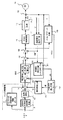
図1は、電動パワーステアリング装置のモータ14を制御するために、トルクを測定する為のセンサより検出されたトルクTと、センサである電圧検出回路16および電流検出回路15より検出したモータの端子電圧Vおよび電流Iとを入力として演算処理した場合の電動パワーステアリング装置の制御装置の一実施例である。
【0022】
まず、電動パワーステアリング装置のモータ14の制御の基本構成について説明する。図示されないトルクセンサで検出されたトルクTは、操舵補助指令値演算回路3とセンター応答性改善回路9とに入力される。つまり、トルクTはアシスト特性マップを有する操舵補助指令値演算3に入力され、電流指令値の基本となる操舵補助指令値I0が出力され、この操舵補助指令値I0は位相補償回路10に入力される。トルクTは、さらに数1の微分特性を有するセンター応答性改善回路9に入力され、加算回路7において、数2の特性を有する位相補償回路10の出力とセンター応答性改善回路9の出力Itが加算される。以上の処理がトルク制御部に相当する。なお、加算回路7では、後述する慣性補償回路23の出力Isも加算される。加算回路7の出力Irefは、電流制御回路11に入力され、電圧指令値Vrefが決定される。
【0023】
【数1】
Ic=dT/dt
【数2】
G(s)=(1+s・T2)/(1+s・T1)
なお、電流制御回路11に関して、電流指令値Irefに対してFB制御をする場合とFF制御をする場合があり、図1では、FF制御を採用した場合の実施例について説明しているが、FB制御の実施例については、後で説明する。よって、電流指令値Irefを数3の位相進み特性を有する電流制御回路11に入力し、新たな指令値Vrefが算出される。
【0024】
【数3】
Vref=(R+s・L)・Iref
モータ14を制御する基本的な指令値はVrefであるが、このVrefにさらに補助信号である逆起電圧EMFと外乱Vdisが加算される。なお、逆起電圧EMFは、モータ14の逆起電圧EMFを電圧検出回路16で検出したモータ端子電圧Vと電流検出回路15で検出した電流Iから後述詳細に説明する逆起電圧算出回路17で算出する。また、外乱VdisはPWM制御回路12に指示したとおりにインバータ回路13が出力しているか監視し、差があれば補償するための信号である。
【0025】
元に戻って、電流制御回路11から出力されたVrefに加算回路20で外乱Vdisが加算され、さらに、加算回路18でEMFが加算され、PWM制御回路12の入力は(Vref+EMF+Vdis)となる。この入力信号に基づきインバータ回路13をPWM制御し、モータ14はインバータ回路14から供給される電流によってトルク制御される。
【0026】
以上が、図1に示すFF制御を適用したモータ14のトルク制御の基本制御であるが、モータ14の出力トルクが、トルク指令値Trefに忠実に高速に応答しトルクリップルも少ないことが望ましい。しかし、上述したノイズの影響により、上記目的達成の妨害要因となり、特に、図1の各処理回路には、多くの微分回路や位相進み回路を適用しており、これらがノイズに対して脆弱なため、本発明を適用する必要がある。
【0027】
微分回路や位相進み回路を適用した各処理回路にデシメーションを施した実施例について、以下、順に説明する。つまり、トルク制御部、逆起電圧算出回路と角加速度算出回路、外乱オブザーバ回路の順に説明する。
【0028】
トルク制御部には、図1において、センター応答性改善回路9が数1の微分演算であり、位相補償回路10には、数2の示す一次進み遅れ演算となっている。そこで、図2にデシメーション処理した場合微分回路とローパスフィルタ回路(以下LPF回路と記す)の組み合わせを示す。また、図3にデシメーション処理した一次進み遅れ回路を示す。
【0029】
図2は近似微分回路9−1とLPF回路9−2の組み合わせたから構成されている。近似微分回路9−1は遅延回路9−3,9−4と減算回路9−6から構成されている。即ち、近似微分回路9−1の入力は遅延回路9−3と減算回路9−6に入力され、微分回路9−3の出力は微分回路9−4に入力されている。微分回路9−4の出力が減算回路9−6の入力となり、減算回路9−6の出力が近似微分回路9−1の出力となる。
【0030】
また、LPF回路9−2は遅延回路9−5と減算回路9−7と加算回路9−8および増幅回路9−9,9−10から構成されている。即ち、近似微分回路9−1の出力がLPF回路9−2の入力となり、まず、減算回路9−7の入力となる。また、増幅回路9−9の出力が減算回路9−7の他方の入力となり、減算回路9−7の出力が遅延回路9−5および加算回路9−8の入力となる。遅延回路9−5の出力は増幅回路9−9の入力および加算回路9−8の入力となる。加算回路9−8の出力が増幅回路9−10に入力され、増幅回路9−10の出力がLPF回路9−2の出力となる。
【0031】
ここで重要なことは、微分回路9−1の遅延回路9−4がデシメーションの作用をして間引き効果をもち、サンプリング時間を大きくとることによりノイズの除去に効果がある。また、LPF回路9−2のサンプリング時間を微分回路9−1のサンプリング時間より小さくすることにより高周波領域での遅れを小さくすることができ高速応答性を有する。
【0032】
このデシメーションの効果をボード線図で示すと図4のようになる。図4は、デシメーションした近似微分とLPF回路の組み合わせ及び従来の近似微分とLPF回路の組み合わせとをボード線図上で比較したものである。図4において、従来の近似微分は、100Hz付近までしか正しく計算できず、また、400Hzでのロールオフ率も大きくない。一方、デシメーションした近似微分は200Hz付近まで正しく近似微分を計算できている。図5はデシメーションした近似微分とLPF回路の組み合わせと従来の近似微分と2次のLPF回路の組み合わせを比較したものである。従来の近似微分でデシメーションした近似微分とLPF回路の組み合わせと同じロールオフ率を得る為にはLPF回路の次数の高い2次のLPF回路にする必要があるが、2次のLPF回路は計算量が多く、また位相遅れも大きくなる問題がある。つまり、デシメーションした近似微分は少ない計算量で位相遅れが小さく、ロールオフ率が大きいという優れた効果を有していることがわかる。
【0033】
このデシメーションの効果をみるために、チャープ波形(周波数が増加する正弦波)を従来の近似微分とLPF回路の組み合わせ及びデシメーションした近似微分とLPF回路の組み合わせに入力した場合の出力結果について図6(A)と図6(B)で比較して示す。図6(A)はデシメーションを利用しない微分とLPF回路の組み合わせ回路を通過させた信号出力であり、図6(B)は図2のデシメーションを利用した微分回路9−1とLPF回路9−2の組合せ回路の信号出力である。明らかに同図(B)のデシメーションを利用した組み合わせ回路の方がノイズが少ないことがわかる。そこで、本回路を図1のセンター応答性改善回路9に適用すれば、ノイズの少ない微分回路によって出力Icが得られる。
【0034】
図3は、位相進み回路10−1とLPF回路9−2との組合せ回路である。位相進み回路10−1は遅延回路10−2,10−3と減算回路10−4と加算回路10−5と増幅回路10−8,10−9、10−10より構成される。即ち、位相進み回路の入力は、まず、減算回路10−4に入力される。減算回路10−4のもうひとつの入力は増幅回路10−8の出力であり、減算回路10−4の出力は増幅回路10−10および遅延回路10−2の入力となる。遅延回路10−2の出力は増幅回路10−8および遅延回路10−3の入力となる。遅延回路10−3の出力が増幅回路10−9の入力になり、増幅回路10−9の出力と増幅回路10−10の出力が加算回路10−5に入力される。加算回路10−5の出力が位相進み回路10−1の出力となる。
【0035】
また、LPF回路9−2は図2のLPF回路9−2と同じである。ここでも位相進み回路10−1の遅延回路10−3でサンプリング時間を大きく取ってノイズの除去を可能とする。その後のLPF回路のサンプリング時間との関係では、LPF回路のサンプリング時間を位相進み回路のサンプリング時間より小さくしてLPF回路の高周波領域での遅れを小さくしている。そこで、図1の位相補償回路10に本回路を適用して、指令値It=(1+s・T2)・I0/(1+s・T1)を算出する。ここでもデシメーションの効果により、位相進み(1+s・T2)でのノイズ除去に効果があり、また、後段のLPF回路の1/(1+s・T1)では、サンプリング時間を小さくして高周波領域での遅れを小さくできる。
【0036】
電流制御回路11の伝達関数は(R+s・L)であるが、この位相進み要素には、図3における位相進み回路10−1と同様の手法を適用すればノイズの除去に効果がある。トルク制御部に関する微分演算、位相進み演算およびそれらとLPF回路の組み合わせ回路への本発明の適用に付いて説明した。
【0037】
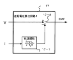
次に、逆起電圧算出回路17に対する本発明の適用について図7を用いて説明する。まず、逆起電圧の算出式を数4に示す。
【0038】
【数4】
EMF=V−(R+s・L)・I/(1+s・Tf)
である。ここで、Rはモータの抵抗、Lはモータのインダクタンスである。
【0039】
この処理を実現するため、図7において、逆起電圧算出回路17は電流Iを入力として伝達関数(R+s/L)/(1+s・Tf)をもつ伝達関数回路17−1とその出力および電圧Vとを入力とする加算回路17−2から構成されている。ここでも電流算出回路16で検出されたノイズを含む電流Iに対して位相進みおよびLPFによるノイズ除去を実行している。この伝達関数回路17−1に図3の位相進み遅れ回路と同様のデシメーション処理を適用すればノイズの除去に効果がある。
【0040】
次に、角加速度αの算出については、数5および数6によって算出することができる。
【0041】
【数5】
ω=EMF/Ke
である。ここで、ωはモータの角速度、Keは逆起電圧定数である。
【0042】
【数6】
α=dω/dt
である。
【0043】
よって、図1の角速度推定回路21では、数5の式を実行して、その後に、角加速度算出回路22でωを入力とし、数6の微分演算によって角加速度αを算出している。ここで、角加速度算出回路21−2は微分演算なので、図2の微分回路9−1とLPF回路9−2の組み合わせ回路を適用すれば、ノイズの除去に効果があり、高応答性を実現できる。
【0044】
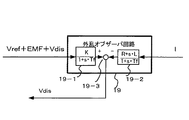
最後に、外乱オブザーバ回路19については、図8を用いて説明する。外乱オブザーバ回路の機能は、入力の指令値(Vref+EMF+Vdis)の指示通りにインバータの出力、即ち、モータ電流Iが出力しているかを監視する機能であって、それらに差があるとその差をフィードバックして差を無くすように機能する。具体的な回路は図8に示す通りである。(Vref+EMF+Vdis)を入力とする伝達関数(k/(1+s・Tf))をもつ伝達関数回路19−1と電流Iを入力とし伝達関数(R+s・L)/(1+s・Tf)をもつ伝達関数回路19−2のそれぞれの出力の差を減算回路19−3でとって、その差を図1の加算回路20にフィードバックしている。そして伝達関数回路19−1および19−2では、それぞれ一次遅れ演算と位相進み遅れ演算を実行しているので、ノイズ除去のために、伝達関数回路19−1の一次遅れ演算には図2のLPF回路を適用し、伝達関数回路19−2の位相進み遅れには、図3の位相進み回路10−1とLPF回路9−2を適用すれば、ノイズ除去に効果がある。
【0045】
以上説明したように、図1の制御回路には多くの微分演算および位相進み演算が存在し、これらは、ノイズを発生、拡大の要因になるが、デシメーションを利用した演算によりノイズの除去に極めて効果がある。
【0046】
以上の説明では、微分回路や位相進み回路にデシメーションを適用した実施例について説明したが、電動パワーステアリング装置の装置構成によっては、つまり大型車用の電動パワーステアリング装置と小型車用の電動パワーステアリング装置の違い等により、サンプリングの時間を大きく取れない場合があり、その場合はデシメーションの効果が多く期待できない恐れがある。
【0047】
そのような場合は、微分回路や位相進み回路をデシメーション処理するのではなく、微分回路や位相進み回路は従来の回路を使用し、その出力にデシメーション処理したLPF回路(デシメーションフィルタ)を配して、組み合わせとしては同じ様な効果を期待できる。
【0048】
デシメーションフィルタの実施例を図9に示す。デシメーションフィルタ9−20は遅延回路9−12,9−13と加算回路9−15、減算回路9−16および増幅回路9−17,9−18,9−19から構成されている。その構成は入力と増幅回路9−17とが加算回路9−15で加算され、加算回路9−15の出力が増幅器9−18および遅延回路9−12の入力となる。遅延回路9−12の出力は増幅回路9−17および遅延回路9−13の入力となる。遅延回路9−13の出力は増幅回路9−19の入力となり、増幅回路9−19の出力と増幅回路9−18の出力が減算回路9−16で減算され、減算回路9−16の出力がデシメーションフィルタ9−20の出力となる。
【0049】
ここでデシメーションは遅延回路9−12、9−13によって実現され、LPF回路9−2より、さらにデシメーション効果を持たせ、ノイズ除去効果を高めている。LPF回路9−2の替わりにデシメーションフィルタ9−20を使用する理由は、例えば、位相進み回路10−1のサンプリング時間を大きくできない場合、ノイズ除去能力の高いデシメーションフィルタ9−20を利用すればノイズを効果的に除去できる。
【0050】
このデシメーションフィルタの効果を図10に示す。図9ではNを一般化した場合の構成図を示したが、図10はN=2、3、5,9およびa=0.02の場合のボード線図である。Nに応じて、カットオフ周波数が変化しており、ゲインを見るとノイズのロールオフ率(遮断性能)が非常に高いことがわかる。
【0051】
このデシメーションフィルタの効果をみるために、このデシメーションフィルタにチャープ波形を入力した場合の出力結果を図11に示す。図11の出力波形と図6(A)のデシメーションを利用しない微分とLPF回路の組み合わせの出力波形とを比較すると、明らかに図11のデシメーションフィルタを通過させた出力波形の方がノイズが少ないことがわかる。
【0052】
本発明を図1のようなFF制御を用いた電動パワーステアリング装置の制御装置に適用した場合について説明したが、本発明は図12に示すようなFB制御をを用いた電動パワーステアリング装置の制御装置に用いても効果がある。図12のFB制御による制御装置と図1のFF制御の制御装置と異なるところは、電流検出回路15で検出したモータ電流Iを電流制御回路200にフィードバックして減算回路201で指令値Irefとの誤差を算出し、その誤差を比例積分回路202に入力して指令値Vrefを算出するところが異なる。しかし、図12におけるFB制御の制御装置で使用される微分演算や位相進み演算あるいはLPF回路などは、図1の演算などと同じであり、ノイズなどに対する効果もFF制御の場合と同じような効果を得ることができる。
【0053】
本発明は、上述したようにセンサ類で検出した電動パワーステアリング装置の状態を示す信号からノイズを除去するときに、本来の状態を示す信号まで除去しないようにする効果を有している。よって、電動パワーステアリング装置の状態を検出するセンサは、実施例で示したモータの端子電圧や電流を検出する電圧検出センサや電流検出センサ、或いは操舵トルクを検出するトルクセンサに限らず、モータの回転数を検出するセンサ、例えば、レゾルバやタコメータなどの他のセンサにも本発明は適用できる。
【0054】
【発明の効果】
以上に説明したように、本発明の電動パワーステアリング装置の制御装置によれば、デシメーションを利用した微分演算や位相進み演算を用いることによって、電動パワーステアリング装置の検出センサ等から検出されたロードインフォメーションなどは除去されずに検出センサなどで発生したノイズだけが除去されることにより、アシストトルクに振動を発生させないようにモータを正しく制御して、不快な異常音や振動のない電動パワーステアリング装置の制御装置を提供できる効果がある。
【図面の簡単な説明】
【図1】本発明を適用するフィードフォワード制御を利用した電動パワーステアリング装置の制御装置の制御ブロック図である。
【図2】本発明のデシメーションを利用した微分演算とLPF回路の演算ブロック図である。
【図3】本発明のデシメーションを利用した位相進み演算とLPF回路の演算ブロック図である。
【図4】デシメーション処理をしない微分演算とデシメーション処理した微分演算によるボード線図の比較を示す図である。
【図5】デシメーション処理をしない微分演算とデシメーション処理した微分演算とLPF回路との組み合わせによるボード線図の比較を示す図である。
【図6】デシメーション処理をしない微分演算(A)とデシメーション処理した微分演算(B)によるノイズ除去効果の比較を示す図である。
【図7】逆起電圧算出回路の詳細な制御ブロック図である。
【図8】外乱オブザーバ回路の詳細な制御ブロック図である。
【図9】本発明のデシメーションを利用したLPF回路の演算ブロック図である。
【図10】デシメーションを利用したLPF回路によるボード線図の比較を示す図である。
【図11】デシメーションフィルタによるノイズ除去効果の比較を示す図である。
【図12】本発明を適用するフィードバック制御を利用した電動パワーステアリング装置の制御装置の制御ブロック図である。
【図13】従来の電動パワーステアリング装置の制御装置の制御ブロック図である。
【符号の説明】
3 操舵補助指令値演算回路
7 加算回路
9 センター応答性改善回路
10 位相補償回路
11 電流制御回路(FF)
12 PWM制御回路
13 インバータ回路
14 モータ
15 電流検出回路
16 電圧検出回路
17 逆起電圧算出回路
18 加算回路
19 外乱オブザーバ回路
20 加算回路
21 角速度推定回路
22 角加速度算出回路
23 慣性補償回路
9−1 微分回路
9−2 LPF回路
9−3,9−4,9−5、9−12,9−13 遅延回路
9−6,9−7 減算回路
9−8、 加算回路
9−9,9−10 増幅回路
10−1 位相進み回路
10−2,10−3 遅延回路
10−4 減算回路
10−5 加算回路
10−8,10−9,10−10 増幅回路
9−20 デシメーションフィルタ
9−12、9−13 遅延回路
9−16 減算回路
9−15 加算回路
9−17,9−18,9−19 増幅回路
200 電流制御回路(FB)
201 減算回路
202 比例積分回路[0001]
BACKGROUND OF THE INVENTION
The present invention relates to a control device for an electric power steering device in which a steering assist force by a motor is applied to a steering system of an automobile or a vehicle, and in particular, attenuates an effective signal without a control delay from a signal input to the control device. The present invention relates to a control device for an electric power steering apparatus that can remove only noise without causing noise.
[0002]
[Prior art]
An electric power steering device for assisting a steering device of an automobile or a vehicle with a rotational force of a motor assists the steering shaft or the rack shaft with a transmission mechanism such as a gear or a belt via a speed reducer. It is designed to give power. Such a conventional electric power steering device accurately generates assist torque (steering assist torque). Therefore, the torque signal from the steering wheel, the motor voltage, and the current signal are detected, and the motor is accurately determined based on these information. Need to control.
[0003]
However, when these signals are detected and input to the control device, noise is superimposed on these signals and the motor cannot be controlled accurately, causing vibrations in the assist torque and unpleasant abnormal sounds for the driver. There is a problem of vibration. Therefore, in order to improve such a problem, a device has been devised so that noise superimposed on the detection signal can be removed without delay in control and without attenuating an effective signal.
[0004]
For example, the method disclosed in
[0005]
To explain the basic idea of the control, the detected torque signal T is input to the target
[0006]
In this example, as a device for removing noise, the command current IA is not directly input to the
[0007]
Making the above-described filter coefficient variable in accordance with the situation indicates that this control element is a kind of adaptive filter (Adaptive Filter). Careful attention must be paid to the design of the adaptive filter. This is because the expected effect cannot be obtained unless the filter coefficients are designed correctly.
[0008]
However, in
[0009]
In addition, as a general feature in control, the differential element and the phase advance element are noise sources or noise expansion sources, and the LPF can remove noise, but the cut-off frequency is reduced to remove low-frequency noise. When trying to do so, there is a problem that the delay in the high frequency region becomes large.
[0010]
As another problem relating to noise, this is a problem that applies to many current control devices, but the detection signal is an analog signal and the control is often digital control, and it is necessary to AD-convert the detection signal. A method for solving the quantization error is disclosed in
[0011]
[Patent Document 1]
JP 2002-234454 A
[0012]
[Patent Document 2]
Japanese Patent Laid-Open No. 10-109656
[0013]
[Problems to be solved by the invention]
As described above, since the motor of the device that generates assist torque cannot be controlled correctly due to noise included in various detection signals of the electric power steering device, vibration or the like occurs in the assist torque, which is uncomfortable for the driver. There is a problem that abnormal noise or vibration occurs.
[0014]
The present invention has been made for the above-described circumstances, and an object of the present invention is to remove noise included in various detection signals of the electric power steering apparatus from the detection signal so as not to generate vibration in the assist torque. It is an object of the present invention to provide a control device for an electric power steering device that correctly controls the motor of the device and does not cause unpleasant abnormal noise or vibration.
[0015]
[Means for Solving the Problems]
The present invention relates to a sensor for detecting a state of an electric power steering apparatus that applies a steering assist force by a motor to a steering system of a vehicle, and a calculation for controlling the electric power steering apparatus by using a signal of the sensor as an input. The above-mentioned object of the present invention is that the arithmetic circuit includes a differential arithmetic circuit or a phase advance arithmetic circuit, and the differential arithmetic circuit or the phase advance arithmetic circuit. Is a decimation process, and includes a low-pass filter at the output of the decimated differential operation circuit or the phase advance operation circuit, the differential operation circuit Or The sampling time of the phase advance arithmetic circuit is achieved by being larger than the sampling time of the low pass filter. The above purpose is The center response improvement circuit and phase compensation circuit, counter electromotive voltage calculation circuit, angular acceleration calculation circuit, and disturbance observer circuit provided in the torque control unit each include the arithmetic circuit. Is achieved. Further, the object is a differential arithmetic circuit in which the arithmetic circuit is not decimated or a phase advance arithmetic circuit that is not decimated, and includes a decimation filter at an output of the differential arithmetic circuit or an output of the phase advance arithmetic circuit, The center response improvement circuit and phase compensation circuit, counter electromotive voltage calculation circuit, angular acceleration calculation circuit, and disturbance observer circuit provided in the torque control unit each include the arithmetic circuit. Is achieved. The above object is achieved by the state of the electric power steering device being the terminal voltage of the motor, the motor current, the steering torque, or the rotational speed of the motor.
[0016]
DETAILED DESCRIPTION OF THE INVENTION
First, decimation related to the main technology of the present invention will be described. Decimation means downsampling or sampling thinning. Generally, decimation is used for sampling rate conversion, but decimation is noise reduction. It also has the function of
[0017]
In general, in the case of differential calculation or phase advance calculation in arithmetic processing, since particularly bad influences due to noise appear, the present invention takes measures against noise for these arithmetic processing.
[0018]
By the way, a noise filter or the like is often used to remove noise included in a sensor signal or the like. However, for example, when an LPF generally used for removing noise is configured by an analog circuit or by a method described in the prior art, information obtained from various sensors, for example, torque T information, The motor voltage and current information is attenuated together with noise, and is attenuated to important road surface information included in the torque T, so that correct electric power steering control cannot be executed.
[0019]
However, in calculations using decimation, only high-frequency noise components are removed, and valuable information contained in sensor signals, that is, useful signals such as torque T signals, motor voltages, and current signals, are processed without being attenuated. It has excellent characteristics. By executing the differential calculation process and the phase advance calculation process using the excellent characteristics by this decimation, the electric power steering apparatus can be correctly controlled without being disturbed by noise.
[0020]
Hereinafter, preferred embodiments of the present invention will be described in detail with reference to the drawings.
[0021]
FIG. 1 shows a torque T detected by a sensor for measuring torque and a motor terminal detected by a
[0022]
First, a basic configuration of control of the
[0023]
[Expression 1]
Ic = dT / dt
[Expression 2]
G (s) = (1 + s · T 2 ) / (1 + s · T 1 )
The
[0024]
[Equation 3]
Vref = (R + s · L) · Iref
The basic command value for controlling the
[0025]
Returning to the original state, the disturbance Vdis is added to the Vref output from the
[0026]
The above is the basic control of the torque control of the
[0027]
Examples in which decimation is applied to each processing circuit to which a differentiation circuit or a phase advance circuit is applied will be described in order below. That is, the torque control unit, the counter electromotive voltage calculation circuit, the angular acceleration calculation circuit, and the disturbance observer circuit will be described in this order.
[0028]
In the torque control unit, the center
[0029]
FIG. 2 includes a combination of an approximate differentiation circuit 9-1 and an LPF circuit 9-2. The approximate differentiation circuit 9-1 includes delay circuits 9-3 and 9-4 and a subtraction circuit 9-6. That is, the input of the approximate differentiation circuit 9-1 is input to the delay circuit 9-3 and the subtraction circuit 9-6, and the output of the differentiation circuit 9-3 is input to the differentiation circuit 9-4. The output of the differentiation circuit 9-4 becomes the input of the subtraction circuit 9-6, and the output of the subtraction circuit 9-6 becomes the output of the approximate differentiation circuit 9-1.
[0030]
The LPF circuit 9-2 includes a delay circuit 9-5, a subtraction circuit 9-7, an addition circuit 9-8, and amplification circuits 9-9 and 9-10. That is, the output of the approximate differentiation circuit 9-1 becomes the input of the LPF circuit 9-2, and first becomes the input of the subtraction circuit 9-7. The output of the amplifier circuit 9-9 becomes the other input of the subtractor circuit 9-7, and the output of the subtractor circuit 9-7 becomes the input of the delay circuit 9-5 and the adder circuit 9-8. The output of the delay circuit 9-5 becomes the input of the amplifier circuit 9-9 and the input of the adder circuit 9-8. The output of the adder circuit 9-8 is input to the amplifier circuit 9-10, and the output of the amplifier circuit 9-10 becomes the output of the LPF circuit 9-2.
[0031]
What is important here is that the delay circuit 9-4 of the differentiating circuit 9-1 has a decimation effect and has a thinning effect, and a longer sampling time is effective in removing noise. Further, by making the sampling time of the LPF circuit 9-2 shorter than the sampling time of the differentiating circuit 9-1, the delay in the high frequency region can be reduced, and high-speed response is achieved.
[0032]
The effect of this decimation is shown in a Bode diagram as shown in FIG. FIG. 4 is a comparison of the decimated approximate derivative and LPF circuit combination and the conventional approximate derivative and LPF circuit combination on the Bode diagram. In FIG. 4, the conventional approximate derivative can be calculated correctly only up to around 100 Hz, and the roll-off rate at 400 Hz is not large. On the other hand, the decimated approximate derivative is correctly calculated up to around 200 Hz. FIG. 5 compares the combination of the decimated approximate derivative and the LPF circuit and the combination of the conventional approximate derivative and the second-order LPF circuit. In order to obtain the same roll-off rate as the combination of the approximate derivative decimated by the conventional approximate derivative and the LPF circuit, it is necessary to use a second-order LPF circuit having a high order of the LPF circuit. In addition, there is a problem that the phase delay is large. That is, it can be seen that the decimated approximate derivative has an excellent effect that the phase delay is small with a small amount of calculation and the roll-off rate is large.
[0033]
In order to see the effect of this decimation, the output result when a chirp waveform (a sine wave with an increasing frequency) is input to the combination of the conventional approximate derivative and the LPF circuit and the combination of the decimated approximate derivative and the LPF circuit is shown in FIG. A) is compared with FIG. 6B. 6A shows a signal output that has passed through a combination circuit of a differentiation and LPF circuit that does not use decimation, and FIG. 6B shows a differentiation circuit 9-1 and an LPF circuit 9-2 that use the decimation in FIG. The signal output of the combinational circuit. Obviously, the combinational circuit using the decimation shown in FIG. Therefore, if this circuit is applied to the center
[0034]
FIG. 3 is a combination circuit of the phase advance circuit 10-1 and the LPF circuit 9-2. The phase advance circuit 10-1 includes delay circuits 10-2 and 10-3, a subtraction circuit 10-4, an addition circuit 10-5, and amplification circuits 10-8, 10-9, and 10-10. That is, the input of the phase advance circuit is first input to the subtraction circuit 10-4. Another input of the subtracting circuit 10-4 is an output of the amplifying circuit 10-8, and an output of the subtracting circuit 10-4 is an input of the amplifying circuit 10-10 and the delay circuit 10-2. The output of the delay circuit 10-2 becomes the input of the amplifier circuit 10-8 and the delay circuit 10-3. The output of the delay circuit 10-3 becomes the input of the amplifier circuit 10-9, and the output of the amplifier circuit 10-9 and the output of the amplifier circuit 10-10 are input to the adder circuit 10-5. The output of the adder circuit 10-5 becomes the output of the phase advance circuit 10-1.
[0035]
The LPF circuit 9-2 is the same as the LPF circuit 9-2 in FIG. Also here, the delay circuit 10-3 of the phase advance circuit 10-1 takes a long sampling time to enable noise removal. In relation to the subsequent sampling time of the LPF circuit, the sampling time of the LPF circuit is made smaller than the sampling time of the phase advance circuit to reduce the delay in the high frequency region of the LPF circuit. Therefore, this circuit is applied to the
[0036]
Although the transfer function of the
[0037]
Next, application of the present invention to the counter electromotive
[0038]
[Expression 4]
EMF = V− (R + s · L) · I / (1 + s · Tf)
It is. Here, R is the resistance of the motor, and L is the inductance of the motor.
[0039]
In order to realize this processing, in FIG. 7, the back electromotive
[0040]
Next, the angular acceleration α can be calculated by
[0041]
[Equation 5]
ω = EMF / Ke
It is. Here, ω is the angular velocity of the motor, and Ke is the counter electromotive voltage constant.
[0042]
[Formula 6]
α = dω / dt
It is.
[0043]
Therefore, the angular
[0044]
Finally, the
[0045]
As described above, the control circuit of FIG. 1 has many differential operations and phase advance operations, which cause noise and cause expansion, but it is extremely difficult to remove noise by operations using decimation. effective.
[0046]
In the above description, the embodiment in which decimation is applied to the differentiation circuit and the phase advance circuit has been described. However, depending on the device configuration of the electric power steering device, that is, the electric power steering device for large vehicles and the electric power steering device for small vehicles. In some cases, the sampling time cannot be increased due to the difference in the number of times, and in this case, there is a possibility that the decimation effect cannot be expected.
[0047]
In such a case, the differentiation circuit and the phase advance circuit are not decimated, but the differentiation circuit and the phase advance circuit use a conventional circuit, and a decimation-processed LPF circuit (decimation filter) is arranged at the output. As a combination, the same effect can be expected.
[0048]
An embodiment of the decimation filter is shown in FIG. The decimation filter 9-20 includes delay circuits 9-12 and 9-13, an adder circuit 9-15, a subtractor circuit 9-16, and amplifier circuits 9-17, 9-18, and 9-19. In the configuration, the input and the amplifier circuit 9-17 are added by the adder circuit 9-15, and the output of the adder circuit 9-15 becomes the input of the amplifier 9-18 and the delay circuit 9-12. The output of the delay circuit 9-12 becomes the input of the amplifier circuit 9-17 and the delay circuit 9-13. The output of the delay circuit 9-13 becomes the input of the amplifier circuit 9-19, the output of the amplifier circuit 9-19 and the output of the amplifier circuit 9-18 are subtracted by the subtractor circuit 9-16, and the output of the subtractor circuit 9-16 is obtained. This is the output of the decimation filter 9-20.
[0049]
Here, the decimation is realized by the delay circuits 9-12 and 9-13, and the decimation effect is further provided by the LPF circuit 9-2 to enhance the noise removal effect. The reason for using the decimation filter 9-20 instead of the LPF circuit 9-2 is that, for example, if the sampling time of the phase advance circuit 10-1 cannot be increased, the noise can be reduced by using the decimation filter 9-20 having a high noise removal capability. Can be effectively removed.
[0050]
The effect of this decimation filter is shown in FIG. FIG. 9 shows a configuration diagram when N is generalized. FIG. 10 is a Bode diagram when N = 2, 3, 5, 9, and a = 0.02. The cut-off frequency changes according to N, and it can be seen from the gain that the noise roll-off rate (cut-off performance) is very high.
[0051]
In order to see the effect of this decimation filter, the output result when a chirp waveform is input to this decimation filter is shown in FIG. Comparing the output waveform of FIG. 11 with the output waveform of the combination of the LPF circuit and the derivative not using decimation of FIG. 6A, the output waveform that has passed through the decimation filter of FIG. 11 clearly has less noise. I understand.
[0052]
Although the case where the present invention is applied to the control device for the electric power steering apparatus using the FF control as shown in FIG. 1 has been described, the present invention controls the electric power steering apparatus using the FB control as shown in FIG. It is effective even when used in an apparatus. The difference between the control device by FB control in FIG. 12 and the control device by FF control in FIG. 1 is that the motor current I detected by the
[0053]
As described above, the present invention has an effect that when a noise is removed from a signal indicating the state of the electric power steering apparatus detected by sensors, a signal indicating the original state is not removed. Therefore, the sensor for detecting the state of the electric power steering device is not limited to the voltage detection sensor, the current detection sensor for detecting the terminal voltage or current of the motor shown in the embodiment, or the torque sensor for detecting the steering torque. The present invention can also be applied to other sensors that detect the number of rotations, such as resolvers and tachometers.
[0054]
【The invention's effect】
As described above, according to the control device for an electric power steering apparatus of the present invention, road information detected from a detection sensor or the like of the electric power steering apparatus by using a differential operation or a phase advance operation using decimation. By removing only the noise generated by the detection sensor, etc. without removing the noise, etc., the motor is correctly controlled so as not to generate vibration in the assist torque. There is an effect that a control device can be provided.
[Brief description of the drawings]
FIG. 1 is a control block diagram of a control device of an electric power steering device using feedforward control to which the present invention is applied.
FIG. 2 is an operational block diagram of a differential operation and LPF circuit using decimation according to the present invention.
FIG. 3 is a calculation block diagram of a phase advance calculation and LPF circuit using decimation according to the present invention.
FIG. 4 is a diagram showing a comparison between Bode diagrams obtained by a differential operation without decimation processing and a differential operation with decimation processing;
FIG. 5 is a diagram showing a comparison of Bode diagrams by a combination of a differential operation without decimation processing, a differential operation with decimation processing, and an LPF circuit.
FIG. 6 is a diagram showing a comparison of a noise removal effect between a differential operation (A) without decimation processing and a differential operation (B) with decimation processing.
FIG. 7 is a detailed control block diagram of a counter electromotive voltage calculation circuit.
FIG. 8 is a detailed control block diagram of a disturbance observer circuit.
FIG. 9 is an operation block diagram of an LPF circuit using decimation according to the present invention.
FIG. 10 is a diagram showing a comparison of Bode diagrams by LPF circuits using decimation.
FIG. 11 is a diagram showing a comparison of a noise removal effect by a decimation filter.
FIG. 12 is a control block diagram of a control device of an electric power steering device using feedback control to which the present invention is applied.
FIG. 13 is a control block diagram of a control device of a conventional electric power steering device.
[Explanation of symbols]
3 Steering assist command value calculation circuit
7 Adder circuit
9 Center response improvement circuit
10 Phase compensation circuit
11 Current control circuit (FF)
12 PWM control circuit
13 Inverter circuit
14 Motor
15 Current detection circuit
16 Voltage detection circuit
17 Back electromotive force calculation circuit
18 Adder circuit
19 Disturbance observer circuit
20 Adder circuit
21 Angular velocity estimation circuit
22 Angular acceleration calculation circuit
23 Inertia compensation circuit
9-1 Differentiation circuit
9-2 LPF circuit
9-3, 9-4, 9-5, 9-12, 9-13 delay circuit
9-6, 9-7 Subtraction circuit
9-8, adder circuit
9-9, 9-10 Amplifier circuit
10-1 Phase advance circuit
10-2, 10-3 delay circuit
10-4 Subtraction circuit
10-5 Adder circuit
10-8, 10-9, 10-10 Amplifier circuit
9-20 Decimation filter
9-12, 9-13 Delay circuit
9-16 Subtraction circuit
9-15 Adder circuit
9-17, 9-18, 9-19 Amplifier circuit
200 Current control circuit (FB)
201 Subtraction circuit
202 Proportional integration circuit
Claims (4)
デシメーション処理された前記微分演算回路又は前記位相進み演算回路の出力にローパスフィルタを備え、前記微分演算回路又は前記位相進み演算回路のサンプリング時間が前記ローパスフィルタのサンプリング時間より大きいことを特徴とする電動パワーステアリング装置の制御装置。A sensor for detecting a state of an electric power steering apparatus that applies a steering assist force by a motor to a steering system of a vehicle, and an arithmetic circuit for controlling the electric power steering apparatus by using a signal of the sensor as an input. In the control device for the electric power steering apparatus, the arithmetic circuit has a differential arithmetic circuit or a phase advance arithmetic circuit, and the arithmetic operation of the differential arithmetic circuit or the phase advance arithmetic circuit is an operation for decimation processing,
An electric motor comprising a low-pass filter at an output of the differential operation circuit or the phase advance operation circuit subjected to the decimation processing, wherein a sampling time of the differentiation operation circuit or the phase advance operation circuit is longer than a sampling time of the low pass filter Control device for power steering device.
トルク制御部において具備されたセンター応答性改善回路及び位相補償回路と、逆起電圧算出回路と、角加速度算出回路と、外乱オブザーバ回路とがそれぞれ前記演算回路を具備していることを特徴とする電動パワーステアリング装置の制御装置。A sensor for detecting a state of an electric power steering apparatus that applies a steering assist force by a motor to a steering system of a vehicle, and an arithmetic circuit for controlling the electric power steering apparatus by using a signal of the sensor as an input. In the control device for the electric power steering apparatus, the arithmetic circuit is a differential arithmetic circuit that is not decimated or a phase advance arithmetic circuit that is not decimated, and a decimation filter is applied to an output of the differential arithmetic circuit or an output of the phase advance arithmetic circuit. Prepared,
A center response improvement circuit and phase compensation circuit, a back electromotive force calculation circuit, an angular acceleration calculation circuit, and a disturbance observer circuit provided in the torque control unit each include the arithmetic circuit. Control device for electric power steering device.
Priority Applications (5)
| Application Number | Priority Date | Filing Date | Title |
|---|---|---|---|
| JP2003147759A JP4307154B2 (en) | 2003-05-26 | 2003-05-26 | Control device for electric power steering device |
| PCT/JP2004/006886 WO2004103800A1 (en) | 2003-05-26 | 2004-05-14 | Electric power steering device controller |
| EP04733127A EP1627797B1 (en) | 2003-05-26 | 2004-05-14 | Electric power steering device controller |
| DE602004022043T DE602004022043D1 (en) | 2003-05-26 | 2004-05-14 | ELECTRIC POWER STEERING CONTROL |
| US10/555,943 US20070107978A1 (en) | 2003-05-26 | 2004-05-14 | Control unit for electric power steering apparatus |
Applications Claiming Priority (1)
| Application Number | Priority Date | Filing Date | Title |
|---|---|---|---|
| JP2003147759A JP4307154B2 (en) | 2003-05-26 | 2003-05-26 | Control device for electric power steering device |
Publications (2)
| Publication Number | Publication Date |
|---|---|
| JP2004345596A JP2004345596A (en) | 2004-12-09 |
| JP4307154B2 true JP4307154B2 (en) | 2009-08-05 |
Family
ID=33475374
Family Applications (1)
| Application Number | Title | Priority Date | Filing Date |
|---|---|---|---|
| JP2003147759A Expired - Fee Related JP4307154B2 (en) | 2003-05-26 | 2003-05-26 | Control device for electric power steering device |
Country Status (5)
| Country | Link |
|---|---|
| US (1) | US20070107978A1 (en) |
| EP (1) | EP1627797B1 (en) |
| JP (1) | JP4307154B2 (en) |
| DE (1) | DE602004022043D1 (en) |
| WO (1) | WO2004103800A1 (en) |
Cited By (1)
| Publication number | Priority date | Publication date | Assignee | Title |
|---|---|---|---|---|
| JP2017127105A (en) * | 2016-01-13 | 2017-07-20 | 日本精工株式会社 | Motor controller and electric power steering device including the same |
Families Citing this family (24)
| Publication number | Priority date | Publication date | Assignee | Title |
|---|---|---|---|---|
| DE102004051338A1 (en) * | 2004-10-21 | 2006-04-27 | Bayerische Motoren Werke Ag | Device for reducing steering wheel torsional vibrations on a motor vehicle and operating method therefor |
| JP2006287620A (en) * | 2005-03-31 | 2006-10-19 | Tokai Rubber Ind Ltd | Signal processor |
| JP5011700B2 (en) * | 2005-09-23 | 2012-08-29 | 日本電産株式会社 | Power steering electric drive |
| JP5034375B2 (en) * | 2006-08-25 | 2012-09-26 | 日本精工株式会社 | Electric power steering device |
| US8744682B2 (en) * | 2008-05-30 | 2014-06-03 | GM Global Technology Operations LLC | Reducing the effects of vibrations in an electric power steering (EPS) system |
| JP2010069975A (en) * | 2008-09-17 | 2010-04-02 | Honda Motor Co Ltd | Electric power steering device |
| ATE552648T1 (en) * | 2008-10-21 | 2012-04-15 | Hella Kgaa Hueck & Co | METHOD FOR AUTOMATICALLY DETERMINING THE SYSTEM DYNAMICS AND/OR THE POSITION OF A PERMANENTLY EXCITED DC MOTOR |
| US8853988B2 (en) * | 2009-03-18 | 2014-10-07 | Nikon Corporation | Control systems and methods for compensating for effects of a stage motor |
| JP2011027445A (en) * | 2009-07-22 | 2011-02-10 | Mitsutoyo Corp | Over-damped accelerometer and seismometer |
| US8831854B2 (en) * | 2010-08-16 | 2014-09-09 | Chrysler Group Llc | Active shimmy mitigation |
| US9266558B2 (en) | 2010-09-15 | 2016-02-23 | GM Global Technology Operations LLC | Methods, systems and apparatus for steering wheel vibration reduction in electric power steering systems |
| US9440674B2 (en) | 2010-09-15 | 2016-09-13 | GM Global Technology Operations LLC | Methods, systems and apparatus for steering wheel vibration reduction in electric power steering systems |
| US9327762B2 (en) | 2010-12-14 | 2016-05-03 | GM Global Technology Operations LLC | Electric power steering systems with improved road feel |
| JP5338946B2 (en) * | 2012-06-11 | 2013-11-13 | 日本精工株式会社 | Electric power steering device |
| GB201304156D0 (en) * | 2013-03-07 | 2013-04-24 | Trw Ltd | Motor Control |
| JP6314552B2 (en) * | 2014-03-07 | 2018-04-25 | 株式会社ジェイテクト | Electric power steering device |
| FR3021469B1 (en) * | 2014-05-21 | 2016-06-24 | Commissariat A L`Energie Atomique Et Aux Energies Alternatives | METHOD OF TORQUE CONTROL OF AN ELECTRIC MOTOR |
| WO2016047280A1 (en) * | 2014-09-22 | 2016-03-31 | 日本精工株式会社 | Electrically actuated power steering device |
| JP6103164B2 (en) * | 2014-12-25 | 2017-04-05 | 日本精工株式会社 | Electric power steering device |
| KR101684513B1 (en) | 2015-04-28 | 2016-12-08 | 현대자동차 주식회사 | Device for controlling restoration of MDPS system |
| JP2018007454A (en) * | 2016-07-05 | 2018-01-11 | 日本精工株式会社 | Motor control device and electric power steering device loading the same |
| GB201617387D0 (en) * | 2016-10-13 | 2016-11-30 | Trw Automotive Gmbh | Control system for electric motor circuit |
| KR20210036531A (en) * | 2019-09-26 | 2021-04-05 | 현대자동차주식회사 | Apparatus and method of controlling motor driven power steering system |
| US11349424B2 (en) * | 2020-01-10 | 2022-05-31 | Steering Solutions Ip Holding Corporation | Observer design for estimating motor velocity of brush electric power steering system |
Family Cites Families (8)
| Publication number | Priority date | Publication date | Assignee | Title |
|---|---|---|---|---|
| JP3089104B2 (en) * | 1992-06-19 | 2000-09-18 | 株式会社日立製作所 | Moving average filter and A / D converter using the same |
| JP3663782B2 (en) | 1996-10-07 | 2005-06-22 | 日本精工株式会社 | Control device for electric power steering device |
| GB9711374D0 (en) * | 1997-06-02 | 1997-07-30 | H Vin Mats E | Signal processing |
| JP3463513B2 (en) * | 1997-06-24 | 2003-11-05 | 松下電器産業株式会社 | AD converter |
| JP3080045B2 (en) * | 1997-10-08 | 2000-08-21 | トヨタ自動車株式会社 | Steering device |
| US6448724B1 (en) * | 1999-10-28 | 2002-09-10 | Delphi Technologies, Inc. | Apparatus and method for commutation noise reduction |
| JP3884236B2 (en) | 2001-02-06 | 2007-02-21 | 株式会社ジェイテクト | Electric power steering device |
| JP2002370662A (en) * | 2001-06-15 | 2002-12-24 | Koyo Seiko Co Ltd | Electric power steering device |
-
2003
- 2003-05-26 JP JP2003147759A patent/JP4307154B2/en not_active Expired - Fee Related
-
2004
- 2004-05-14 US US10/555,943 patent/US20070107978A1/en not_active Abandoned
- 2004-05-14 WO PCT/JP2004/006886 patent/WO2004103800A1/en active Application Filing
- 2004-05-14 EP EP04733127A patent/EP1627797B1/en not_active Not-in-force
- 2004-05-14 DE DE602004022043T patent/DE602004022043D1/en active Active
Cited By (1)
| Publication number | Priority date | Publication date | Assignee | Title |
|---|---|---|---|---|
| JP2017127105A (en) * | 2016-01-13 | 2017-07-20 | 日本精工株式会社 | Motor controller and electric power steering device including the same |
Also Published As
| Publication number | Publication date |
|---|---|
| EP1627797B1 (en) | 2009-07-15 |
| US20070107978A1 (en) | 2007-05-17 |
| WO2004103800A1 (en) | 2004-12-02 |
| EP1627797A4 (en) | 2007-09-12 |
| JP2004345596A (en) | 2004-12-09 |
| DE602004022043D1 (en) | 2009-08-27 |
| EP1627797A1 (en) | 2006-02-22 |
Similar Documents
| Publication | Publication Date | Title |
|---|---|---|
| JP4307154B2 (en) | Control device for electric power steering device | |
| JP4468415B2 (en) | Electric power steering control device | |
| JP4767315B2 (en) | Electric power steering control device | |
| JP5200033B2 (en) | Electric power steering control device | |
| JP6065016B2 (en) | Electric power steering device | |
| JP5493690B2 (en) | Electric power steering device | |
| JP4227133B2 (en) | Electric power steering control device | |
| JP4776656B2 (en) | Electric power steering control device | |
| JP2017210009A (en) | Electric power steering device | |
| JP6222411B2 (en) | Electric power steering device | |
| US20110054740A1 (en) | Electric power steering control apparatus | |
| JPH05184178A (en) | Actuator controlling device | |
| CN107499373B (en) | Modified static tire model with no torque sensor assistance at zero to low vehicle speeds | |
| JP2010069975A (en) | Electric power steering device | |
| JP3884236B2 (en) | Electric power steering device | |
| JP5880048B2 (en) | Electric vehicle control method and electric vehicle control apparatus | |
| JP4759992B2 (en) | Control device for electric power steering device | |
| JP5850179B2 (en) | Motor control device and motor control method | |
| CN110650885B (en) | Electric power steering apparatus and control method of electric power steering | |
| JP4618614B2 (en) | Electric power steering control device | |
| JP2004040850A (en) | Electric power steering device | |
| JP3294056B2 (en) | Mechanical control system |
Legal Events
| Date | Code | Title | Description |
|---|---|---|---|
| A621 | Written request for application examination |
Free format text: JAPANESE INTERMEDIATE CODE: A621 Effective date: 20051205 |
|
| A131 | Notification of reasons for refusal |
Free format text: JAPANESE INTERMEDIATE CODE: A131 Effective date: 20080624 |
|
| A521 | Written amendment |
Free format text: JAPANESE INTERMEDIATE CODE: A523 Effective date: 20080820 |
|
| A131 | Notification of reasons for refusal |
Free format text: JAPANESE INTERMEDIATE CODE: A131 Effective date: 20080909 |
|
| A521 | Written amendment |
Free format text: JAPANESE INTERMEDIATE CODE: A523 Effective date: 20081106 |
|
| TRDD | Decision of grant or rejection written | ||
| A01 | Written decision to grant a patent or to grant a registration (utility model) |
Free format text: JAPANESE INTERMEDIATE CODE: A01 Effective date: 20090421 |
|
| A01 | Written decision to grant a patent or to grant a registration (utility model) |
Free format text: JAPANESE INTERMEDIATE CODE: A01 |
|
| A61 | First payment of annual fees (during grant procedure) |
Free format text: JAPANESE INTERMEDIATE CODE: A61 Effective date: 20090428 |
|
| R150 | Certificate of patent or registration of utility model |
Ref document number: 4307154 Country of ref document: JP Free format text: JAPANESE INTERMEDIATE CODE: R150 Free format text: JAPANESE INTERMEDIATE CODE: R150 |
|
| FPAY | Renewal fee payment (event date is renewal date of database) |
Free format text: PAYMENT UNTIL: 20120515 Year of fee payment: 3 |
|
| FPAY | Renewal fee payment (event date is renewal date of database) |
Free format text: PAYMENT UNTIL: 20130515 Year of fee payment: 4 |
|
| FPAY | Renewal fee payment (event date is renewal date of database) |
Free format text: PAYMENT UNTIL: 20130515 Year of fee payment: 4 |
|
| FPAY | Renewal fee payment (event date is renewal date of database) |
Free format text: PAYMENT UNTIL: 20140515 Year of fee payment: 5 |
|
| LAPS | Cancellation because of no payment of annual fees |