JP4307002B2 - PRINT SYSTEM, IMAGING DEVICE, AND PRINT OUTPUT METHOD - Google Patents
PRINT SYSTEM, IMAGING DEVICE, AND PRINT OUTPUT METHOD Download PDFInfo
- Publication number
- JP4307002B2 JP4307002B2 JP2002043578A JP2002043578A JP4307002B2 JP 4307002 B2 JP4307002 B2 JP 4307002B2 JP 2002043578 A JP2002043578 A JP 2002043578A JP 2002043578 A JP2002043578 A JP 2002043578A JP 4307002 B2 JP4307002 B2 JP 4307002B2
- Authority
- JP
- Japan
- Prior art keywords
- image
- size
- resizing
- printed
- paper
- Prior art date
- Legal status (The legal status is an assumption and is not a legal conclusion. Google has not performed a legal analysis and makes no representation as to the accuracy of the status listed.)
- Expired - Fee Related
Links
Images


Description
【0001】
【発明の属する技術分野】
本発明は、熱転写記録方式プリンタやインクジェット記録方式プリンタを用いるプリントシステム、撮像装置及びプリント出力方法に関し、より具体的には静止画を記録するスチルカメラやビデオカメラ等の撮像装置によって撮像された画像をプリント出力するのに好適なプリントシステムに関するものである。
【0002】
【従来の技術】
従来から印画用紙に感熱型の用紙を用い、主走査方向に配列された複数個の発熱体を選択的に駆動して、用紙を副走査方向に搬送することで、用紙にドットライン状に印画を行うライン熱転写記録方式のプリンタがある。
【0003】
近年、入力側としてのデジタルカメラやデジタルビデオカメラ、またはスキャナ等の画像を扱う入力機器の進歩に伴い、プリンタ手段として熱転写記録方式のプリンタ装置も注目されている。その理由は、インクジェットプリンタが液滴を飛ばすか飛ばさないかという2値の選択しかないために、小さな液滴を用紙へ着弾させて、誤差拡散等の手法でみかけの解像度と階調性を得ようとするのに対して、熱転写記録方式のプリンタの場合には1つの画素において制御可能な熱の値を容易に変更できるため、1つの画素に対する階調性が多く取ることが可能になるので、インクジェットプリンタに比べて滑らかで高画質な画像を得ることができるという点が挙げられる。
【0004】
また、サーマルヘッドの性能や用紙材料の性能も向上したために、仕上がり品位で銀塩写真にも見劣りしない画像プリントを得ることが可能になっている。近年のデジタルカメラの進歩に歩調を合わせるように、特に自然画像用のプリンタとして注目されている。また、そのインクジェットプリンタも液滴の微細化が進み、実質的に熱転写記録方式に引けを取らない高画質の画像の出力が可能になってきている。
【0005】
そこで、こうしたプリンタ装置とデジタルカメラやデジタルビデオカメラ等の撮像装置を直接的に接続したり、一体的に構成したりして、撮影された画像情報をコンピュータ等の画像情報を処理する機器を介すことなくプリントするシステムも登場している。これらのシステムによれば、デジタルカメラやデジタルビデオからの画像情報を簡単に写真的にプリント出力することが可能になり、大変便利である。
【0006】
これらの一例として、例えば特開平10−243327号公報では画像入力装置と画像出力装置の接続について述べられている。これによれば、画像出力装置と画像入力装置とを接続してなる画像入出力システムであって、画像出力装置は、画像入力装置からの画像信号を受信して出力するとともに、画像入力装置に電力を供給する電源部を有する。また画像入力装置は、画像出力装置に画像データを送信し、かつ画像出力装置から電源電力の供給を受けるための接続ケーブルにより画像出力装置と接続され、画像出力装置から電力供給を受けることの可否を判定する判定手段と、電源部とを有する。
【0007】
そして、判定手段により、画像出力装置から電力供給を受けられると判定された場合は、画像出力装置からの電力を用い、電力供給を受けられないと判定された場合は、電源部からの電力を用いるというものである。これによれば画像出力装置から電力の供給が受けられるので、デジタルカメラ等の画像入力装置の電源の残量を気にすることなくプリント出力できるので極めて効果的である。
【0008】
また、特開平9−65182号公報の複合カメラでは、プリント時の電力省電について述べている。これによれば電子ビューファインダを有し、かつ映像情報を記録媒体へ記録する撮影手段と、映像情報を記録紙へプリント出力するプリンタ手段とを一体化した複合カメラが記述される。プリンタ手段が記録紙へ映像情報をプリント出力している間は、電子ビューファインダへ電力を供給するのを停止するよう制御する制御手段を設けたものである。これによればプリント中は電子ビューファインダへの電力供給をしないので、節電に役立つというものであり、極めて効果的である。
【0009】
【発明が解決しようとする課題】
ところで、一般のプリンタ装置では、印刷するサイズと記録用紙サイズとは独立に指定されるため、記録用紙に見合ったサイズで印刷がなされないといった不具合があった。
【0010】
前記従来例に記したプリンタ装置とデジタルカメラ等の撮像装置とのシステムにおいても、プリンタが扱うことのできる記録用紙が複数種である場合に、その記録用紙種によって、撮像装置からの画像情報を記録用紙に見合った大きさにリサイズ(画像の拡大もしくは縮小処理)した方が使い勝手が良い。
【0011】
また、撮像装置に保存されている画像の一部を切り出して印刷する機能がある場合には、プリンタ装置に装着されている記録用紙毎に電子ビューファインダ上に印刷される領域を枠で囲んで表示すると、ユーザは印刷される領域を視覚的に認識することができ便利である。
【0012】
本発明は前記のような問題点を考慮したものであり、記録用紙サイズが複数種であっても、また、プリントスタイルが選択可能とされていても、最適なプリントデータを生成して良好なプリント出力を行えるようにすることを目的とするものである。
【0013】
【課題を解決するための手段】
本発明のプリントシステムは、撮影される被写界の光学像を画像情報に変換する撮像装置と、前記撮像装置によって撮像された画像を記録用紙に視認可能にプリント出力するプリンタ装置とが接続されたプリントシステムであって、用紙内に余白を残さない縁無し印刷モード、または、用紙内に余白を残す縁あり印刷モードのいずれかを印刷実行の指示前に設定する設定手段と、印刷実行の指示が入力されたことに応じて、前記プリンタ装置に装着されている用紙に関する情報を取得する取得手段と、前記取得手段により取得した用紙サイズと、前記設定手段により設定された印刷モードに応じて、印刷対象の画像をリサイズする際に目標とする目標サイズを設定する目標サイズ設定手段と、前記目標サイズとなるようにリサイズ率を算出し、印刷対象の画像をリサイズするリサイズ手段と、前記リサイズ手段によりリサイズした画像に基づいてプリントデータを生成するプリントデータ生成手段とを有し、前記目標サイズ設定手段は、前記設定手段により縁無し印刷モードが設定されている場合は、前記目標サイズを前記用紙サイズよりも大きいサイズとし、前記設定手段により縁あり印刷モードが設定されている場合は、前記目標サイズを前記用紙サイズよりも小さいサイズとし、前記リサイズ手段は、前記印刷対象の画像の横サイズをXi、縦サイズをYiとし、前記プリンタ装置に装着されている用紙の横方向のサイズをXp、縦方向のサイズをYpとし、前記目標サイズの横方向のサイズをXt、縦方向のサイズをYtとすると、Yi/YtおよびXi/Xtを算出し、前記縁無し印刷モードに設定されている場合は、Yi/YtまたはXi/Xtのうちの小さい方をリサイズ率として選択し、前記縁あり印刷モードに設定されている場合は、Yi/YtまたはXi/Xtのうちの大きい方をリサイズ率として選択するリサイズ率選択手段と、前記印刷対象の画像のアスペクト比および目標サイズのアスペクト比がYi/Xi>Yt/Xtである場合は、前記縁無し印刷モードに設定されているときは横方向基準と決定し、前記縁あり印刷モードに設定されているときは縦方向基準と決定し、前記印刷対象の画像のアスペクト比および目標サイズのアスペクト比がYi/Xi<Yt/Xtである場合は、前記縁無し印刷モードに設定されているときは縦方向基準と決定し、前記縁あり印刷モードに設定されているときは横方向基準と決定する基準決定手段とを有し、前記リサイズ率選択手段で選択したリサイズ率と前記基準決定手段で決定した基準とに基づいて、前記印刷対象の画像をリサイズする点に特徴を有する。
【0014】
本発明の撮像装置は、撮影される被写界の光学像を画像情報に変換する撮像手段を備え、前記撮像手段によって撮像された画像を記録用紙に視認可能にプリント出力するプリンタ装置と通信可能とされた撮像装置であって、用紙内に余白を残さない縁無し印刷モード、または、用紙内に余白を残す縁あり印刷モードのいずれかを印刷実行の指示前に設定する設定手段と、印刷実行の指示が入力されたことに応じて、前記プリンタ装置に装着されている用紙に関する情報を取得する取得手段と、前記取得手段により取得した用紙サイズと、前記設定手段により設定された印刷モードに応じて、印刷対象の画像をリサイズする際に目標とする目標サイズを設定する目標サイズ設定手段と、前記目標サイズとなるようにリサイズ率を算出し、印刷対象の画像をリサイズするリサイズ手段と、前記リサイズ手段によりリサイズした画像に基づいてプリントデータを生成するプリントデータ生成手段とを有し、前記目標サイズ設定手段は、前記設定手段により縁無し印刷モードが設定されている場合は、前記目標サイズを前記用紙サイズよりも大きいサイズとし、前記設定手段により縁あり印刷モードが設定されている場合は、前記目標サイズを前記用紙サイズよりも小さいサイズとし、前記リサイズ手段は、前記印刷対象の画像の横サイズをXi、縦サイズをYiとし、前記プリンタ装置に装着されている用紙の横方向のサイズをXp、縦方向のサイズをYpとし、前記目標サイズの横方向のサイズをXt、縦方向のサイズをYtとすると、Yi/YtおよびXi/Xtを算出し、前記縁無し印刷モードに設定されている場合は、Yi/YtまたはXi/Xtのうちの小さい方をリサイズ率として選択し、前記縁あり印刷モードに設定されている場合は、Yi/YtまたはXi/Xtのうちの大きい方をリサイズ率として選択するリサイズ率選択手段と、前記印刷対象の画像のアスペクト比および目標サイズのアスペクト比がYi/Xi>Yt/Xtである場合は、前記縁無し印刷モードに設定されているときは横方向基準と決定し、前記縁あり印刷モードに設定されているときは縦方向基準と決定し、前記印刷対象の画像のアスペクト比および目標サイズのアスペクト比がYi/Xi<Yt/Xtである場合は、前記縁無し印刷モードに設定されているときは縦方向基準と決定し、前記縁あり印刷モードに設定されているときは横方向基準と決定する基準決定手段とを有し、前記リサイズ率選択手段で選択したリサイズ率と前記基準決定手段で決定した基準とに基づいて、前記印刷対象の画像をリサイズする点に特徴を有する。
【0015】
本発明のプリント出力方法は、撮像装置によって撮像された画像をプリンタ装置により記録用紙に視認可能にプリント出力するためのプリント出力方法であって、用紙内に余白を残さない縁無し印刷モード、または、用紙内に余白を残す縁あり印刷モードのいずれかを印刷実行の指示前に設定する設定手順と、印刷実行の指示が入力されたことに応じて、前記プリンタ装置に装着されている用紙に関する情報を取得する取得手順と、前記取得手順により取得した用紙サイズと、前記設定手順により設定された印刷モードに応じて、印刷対象の画像をリサイズする際に目標とする目標サイズを設定する目標サイズ設定手順と、前記目標サイズとなるようにリサイズ率を算出し、印刷対象の画像をリサイズするリサイズ手順と、前記リサイズ手順によりリサイズした画像に基づいてプリントデータを生成するプリントデータ生成手順とを有し、前記目標サイズ設定手順では、前記設定手順により縁無し印刷モードが設定されている場合は、前記目標サイズを前記用紙サイズよりも大きいサイズとし、前記設定手順により縁あり印刷モードが設定されている場合は、前記目標サイズを前記用紙サイズよりも小さいサイズとし、前記リサイズ手順では、前記印刷対象の画像の横サイズをXi、縦サイズをYiとし、前記プリンタ装置に装着されている用紙の横方向のサイズをXp、縦方向のサイズをYpとし、前記目標サイズの横方向のサイズをXt、縦方向のサイズをYtとすると、Yi/YtおよびXi/Xtを算出し、前記縁無し印刷モードに設定されている場合は、Yi/YtまたはXi/Xtのうちの小さい方をリサイズ率として選択し、前記縁あり印刷モードに設定されている場合は、Yi/YtまたはXi/Xtのうちの大きい方をリサイズ率として選択するリサイズ率選択手順と、前記印刷対象の画像のアスペクト比および目標サイズのアスペクト比がYi/Xi>Yt/Xtである場合は、前記縁無し印刷モードに設定されているときは横方向基準と決定し、前記縁あり印刷モードに設定されているときは縦方向基準と決定し、前記印刷対象の画像のアスペクト比および目標サイズのアスペクト比がYi/Xi<Yt/Xtである場合は、前記縁無し印刷モードに設定されているときは縦方向基準と決定し、前記縁あり印刷モードに設定されているときは横方向基準と決定する基準決定手順とを有し、前記リサイズ率選択手順で選択したリサイズ率と前記基準決定手順で決定した基準とに基づいて、前記印刷対象の画像をリサイズする点に特徴を有する。
【0019】
【発明の実施の形態】
以下、図面を参照して、本発明のプリントシステム、撮像装置、プリント出力方法、プログラム、及びコンピュータ読み取り可能な記憶媒体の実施の形態を説明する。
【0020】
(第1の実施の形態)
以下、図1〜4を参照して第1の実施の形態について説明する。本実施の形態のプリントシステムでは、プリンタ手段に昇華型の熱転写記録方式のプリンタ装置を採用し、電子的な画像の情報を任意なプリント枚数分プリント出力することができる。このプリントシステムについて手順に従って説明する。
【0021】
熱転写記録方式のプリンタ装置の一例について、図面を参照して具体的に説明する。図1は、プリンタ装置の側面の構成模式図である。まず、プリンタ装置の全体構成について説明すると、装置本体1には記録紙Pを積載した用紙カセット2から給紙ローラ3で記録紙Pが1枚ずつ分離給送される。この際、記録紙Pはバネ20によって付勢された押上げ板21によって給紙ローラ3に当接している。そして、給紙ローラ3によって搬送された記録紙Pは、搬送ローラ対4で挟持搬送されて記録部を往復可能にしている。搬送ローラ対4は、ピンチローラ42とグリップローラ41で構成されている。
【0022】
記録部においては記録紙搬送経路を挟んで、プラテンローラ5と記録情報に応じて発熱するサーマルヘッド6が対向している。インクカセット7に収納される熱溶融性または熱昇華性インクを塗布したインク層と印画面を保護するために印画面上にオーバコートされるオーバコート層とを持つインクシート8を、サーマルヘッド6によって記録紙Pに押圧するとともに、選択的に加熱することにより記録紙Pに所定画像を転写記録し、保護層をオーバコートする。
【0023】
インクシートは、記録紙Pの印画領域を覆ってそのサイズと略等しいサイズでイエロー(Y)、マゼンタ(M)、シアン(C)の各インク層とオーバコート(OP)層が並べて設けられたものであり、各層ずつ熱転写しては、記録紙Pを記録開始位置に戻し、記録紙上に順次重ねて転写される。このように記録紙Pは搬送ローラ対4により、各色インクおよびオーバコート層の数だけ往復される。
【0024】
この際、各インク層の印画後の記録紙Pは装置本体1前方で反転され、用紙カセット前方部および下部のガイド部を介して装置本体1の後方へ導紙される。装置本体1前方で反転されるために、印画途中の記録紙Pが外部に出ることによるスペースの無駄や意図せずに触ってしまうようなことがなく、設置場所の省スペース化等を可能にしている。しかも、用紙カセット2の下部を紙ガイドとして直接利用していることによって、装置本体1の厚さを薄くすることが可能になる。また、記録紙Pをインクカセット7と用紙カセット2に挟まれた空間を通すことで、装置本体1の全高を最小限にとどめることが可能であり、これにより装置の小型化を可能にしている。
【0025】
25は用紙カセット2の用紙搬送ガイド部である。装置本体1前方から反転されてきた記録紙Pを、装置本体1後方に反転させるガイド部であり、この用紙カセット2に具備することで装置本体1全体の小型化に大きく寄与している。また26は印画されて排紙された記録紙Pの排紙トレイ部であり、用紙カセット2の上面が兼用しており、これも装置本体1の小型化に寄与している。
【0026】
各インク層の印画終了後に、記録紙Pは排紙ローラ9a、9bへ案内され、装置本体1後方から前方に向かって排出され記録動作が終了する。排出ローラ9aは記録紙Pの排出動作時のみ圧接するように構成され、印画中にはストレスがかからないように構成されている。なお、装置本体1には記録紙Pのガイド部15が構成されており、記録紙Pを導紙している。15aは搬送路切替えシートであり、記録紙Pが給紙された後は記録紙Pは排出側の経路に導紙されるようになっている。
【0027】
また、印画用のサーマルヘッド6はヘッドアーム22に一体的に具備されており、インクカセット7を交換する場合にはインクカセット7の抜き差しに支障ない位置まで退避する。この退避動作は、インクカセット7の交換が用紙カセット2を引き抜くと可能になる。この際、用紙カセット2の着脱動作に連動してヘッドアーム22は、そのカム部によって押さえられている状態から、用紙カセット2のカム部が退避していくことで上下動するように構成されている。
【0028】
熱転写記録方式のプリンタ装置ではYMC3色を3回面順次で記録するため、各色の記録先端を正確に合致させる制御が必要となる。このためには、図1に示す搬送ローラ対4で記録紙Pを離さず、しっかり挟持して搬送を行う必要がある。このため記録紙Pの送り方向の端部には、記録不可能な余白部が必要となる。この点に鑑みて終的に容易に、縁のない印画物を得るために、図3に示すように記録紙Pには、記録開始時に搬送ローラ対4でしっかり挟持され、記録できない余白部16を後で容易に手で切取り可能とするためのミシン目12が設けられる。
【0029】
本実施の形態では、上述したミシン目12を持つ記録紙Pと熱転写記録方式のプリンタ装置を用いて実施され、前記記録紙Pに設けられたミシン目12の領域にはオーバコートするものとする。また、左下がり斜線で示す領域は印画の領域(印画領域17)であり、ミシン目12を含む領域を印画するように制御される。オーバコートは略印画される領域であり、かつ印画される領域よりもやや大きく印画される領域を含んで印画するように制御される。
【0030】
以下さらに、プリンタ装置に関わる詳しい説明をする。図1に示すプリンタ装置において、搬送ローラ対4は、ピンチローラ42とグリップローラ41からなる。このグリップローラ41は、図示しないステッピングモータの出力軸が減速機構を介して直結され、該ステッピングモータの回転制御により、正逆転自在に駆動される。記録紙Pは搬送ローラ対4によりしっかりと挟持され、往復搬送されるものであるから、記録紙Pもまた、ステッピングモータの回転制御により、正確に位置制御され搬送駆動される。
【0031】
いま、一例としてサーマルヘッド6による1ライン分の記録ピッチを85μmとし、記録紙Pを1ライン分搬送するためのステッピングモータのステップ数を4ステップとする。このとき記録紙Pは、ステッピングモータを4ステップで回転制御することにより、1ライン(すなわち85μm)搬送することができる。図4に示した印画範囲は搬送方向において144mmであるとすると、1694ライン印画可能であり、記録紙をこの分搬送するためには、ステッピングモータを6776ステップ分回転させればよい。
【0032】
図1に示すプリンタ装置において、給紙ローラ3から給紙ローラ対4を見て給紙ローラ対4の近傍の位置に記録紙先端検出センサ10が置かれる。これにより記録紙Pの先端を検出し、その検出後、搬送ローラ対4で挟持できる範囲で所定ラインを送り停止させる。この位置が前述の記録開始時の位置となる。ここからまず最初のYイエローからサーマルヘッドを記録情報に応じて発熱駆動し、各色インクの所定画像を記録し、またはオーバコート層を転写する。1色が終わるとつぎにこの位置から記録紙を排紙ローラ9のある方向に戻して搬送し、再び所定のライン数を戻し送り、YMC各色およびオーバコート層転写を4回繰り返す。
【0033】
図1に示す装置本体1において、記録紙先端検出センサ10と、プラテンローラ5およびサーマルヘッド6により記録紙Pを押圧する位置との距離は、装置内の部品配置を考慮し、記録紙P上の距離で20mmに設定したが、これに限られるものではない。このとき図3に示す印画物は、下記のように各色インクを転写記録し、またオーバコート層を転写することにより得られる。
【0034】
図2のフローチャートにおいて、色インク転写およびオーバコートシーケンスを説明する。
ステップS1:ユーザは、図示しないプリントボタンもしくはデジタルカメラやデジタルビデオカメラからの印画指示等によってプリント動作を指示する。
ステップS2:装置本体1内部の処理回路18は、プリント指示を実行した機器との通信を開始し、処理回路18ではプリント指示を実行した機器との間でプリントに必要な諸条件の確認や、必要であれば画像情報の印画情報への画像処理を行う。
【0035】
ステップS3:印画準備ができたらCPU等によって構成される制御手段は、給紙ローラ3に連結されたモータを駆動して記録紙Pを給紙開始する。
ステップS4:記録紙Pの先端検出後、ステッピングモータを所定ステップ分回転させ、印画を開始する。このとき印画開始位置は、記録紙先端を基準として、12.465mmとした。
ステップS5:引き続き、ステッピングモータを4ステップ分回転しながら、サーマルヘッドを発熱駆動し1ライン分の印画を行う。全部で6776ステップ分(1694ライン分)回転させ、印画を終了する。このときの印画終了位置は、記録紙先端を基準として、156.455mmとなる。
【0036】
ステップS6:ついで、停止にいたるまでの減速のため、ステッピングモータを10ライン分(40ステップ)程回転させ、停止させる。
ステップS7:この状態から、ステッピングモータを逆転駆動し、記録紙Pを印画時と逆方向に搬送する。所定のステップ数(6776ステップ減速分)だけ戻して、さらに減速のため所定のライン数の10ライン分(40ステップ分)程回転させ、停止させる。
【0037】
ステップS8:前記動作をYMC3色分、3回程繰返し、所望の印画像を記録紙Pに転写記録する。
ステップS9:その後、さらに1回、印画面保護のためのオーバコート層を転写する。
ステップS10:その後、ステッピングモータを逆転駆動して、そのまま排出ローラ3へ導き、排出ローラ3の駆動で用紙を排出して一連の動作を終了させる。
【0038】
また、前記において制御手段は記録紙Pの給紙時に、最初に記録紙先端検出センサ10で検知した記録紙の先端検出信号を基に、ステッピングモータのステップ数と記録紙Pの搬送時における位置関係に基づいて、ステッピングモータの回転駆動のステップ数を、全印画記録時において管理する。そして、これにより記録位置管理を行うとしたが、これに限らず各YMC色およびオーバコート層の転写記録時において、記録紙先端部に検出センサを設けて記録紙の先端検出を行ってもよい。そして、その信号を基準として、ステッピングモータの回転駆動のステップ数を管理することにより、記録位置管理を行う構成としてもよい。
【0039】
また、前記においてオーバコート層の転写は、サーマルヘッドの発熱駆動のON/OFFのみで行うように記述したが、オーバコートの転写開始時では、徐々に発熱量を増加させ、またオーバコートの転写終了時には、徐々に発熱量を減少させることにより得るような制御を加えることも可能である。
【0040】
さて、ここで本発明に関わる内容についてさらに詳細に述べる。前述のステップS2のプリント指示を実行する機器と、プリンタ装置との通信について更に詳述する。一例として、いまプリント指示を実行するのはデジタルカメラDCとして説明する。
【0041】
図4はデジタルカメラDCとプリンタ装置の装置本体1とを接続してある模式図である。デジタルカメラDCは撮影後に該デジタルカメラDC内部のメモリに画像情報が保持するものとする。メモリはコンパクト(R)フラッシュカードやスマートメデイアといった着脱自由なものが便利である。
【0042】
いま、デジタルカメラDCのモードを設定して、任意の画像を再生させるものとする。画像情報の再生は、デジタルカメラDCの具備する液晶表示装置によって随時確認できるので、ユーザは撮影された好きな画像情報を任意に呼び出すことが可能である。
【0043】
ケーブル27や無線手段によってプリンタ装置と通信可能な状態であると、所定のプリント実行ボタン(図不示)によってデジタルカメラDCからプリンタ装置へ必要な情報が通信され、プリンタ装置からプリント出力が得られるというものである。
【0044】
前記必要な情報としては、デジタルカメラDCとのネゴシエーションの情報、デジタルカメラDCからのプリントすべき画像の情報や画像情報に記録時または記録後から付加された情報等である。
【0045】
図5は、本実施の形態における印刷動作を示すフローチャートである。実行ボタンが押下されると(ステップS501)、プリンタ装置に装着されている記録用紙種が検出されてデジタルカメラDCに送信される(ステップS502)。この記録用紙情報を受けて、デジタルカメラDCは記録用紙サイズに見合った大きさにリサイズするために記録用紙サイズ毎にリサイズ処理ステップS506〜S508が振り分けられる(ステップS503〜S505)。もし、デジタルカメラDCが対応していない記録用紙サイズがプリンタ装置から指定された場合は、エラーとして処理され、印刷は行われない(ステップS509)。
【0046】
ステップS506〜S508それぞれにおいてリサイズ処理された画像データは、プリントデータとして加工生成され、プリンタ装置に送信されて印刷が行われる(ステップS510)。
【0047】
ここで、ステップS506〜S508において実行されるリサイズ処理について詳述する。デジタルカメラDCに保存されている画像データをプリンタ装置に装着されている記録用紙サイズにリサイズする場合、記録用紙内に余白を残す縁あり印刷か、全面印刷を行う縁無し印刷かでリサイズ目標値が変わってくる。縁無し印刷、縁あり印刷の指定は印刷実行前にプリントスタイルとしてユーザが設定する。
【0048】
図6を参照して、縁あり印刷と縁無し印刷とによるリサイズ目標値の違いについて説明する。図6(A)は縁無し印刷時の記録用紙サイズXpaper、Ypaperとリサイズ目標値Xtarget、Ytargetとの関係を図示したものである。縁無し印刷であるため、リサイズ目標値を記録用紙サイズより大きく設定し、印刷時に余白が残らないようにしている。
【0049】
図6(B)は縁あり印刷時の縦横の記録用紙サイズXpaper、Ypaperと縦横のリサイズ目標値Xtarget、Ytargetとの関係を図示したものである。縁あり印刷であるため、記録用紙サイズよりリサイズ目標値を小さく設定し、印刷時に余白が残るようにしている。
【0050】
以上、プリントスタイルによってリサイズ目標値が変わることについて述べてきたが、記録用紙サイズによってもリサイズ目標値は変わるため、プリンタ装置が扱う全ての記録用紙サイズとプリントスタイルとによるリサイズ目標値があらかじめデジタルカメラDCに用意されている。
【0051】
本実施の形態では、サイズ1〜3の3サイズについて扱うことができる構成になっているが、扱う記録用紙種分だけのリサイズ目標値を備えていれば、用紙種の数に制限はない。
【0052】
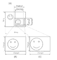
次に、図7を参照して、図7(A)〜(D)では記録用紙に余白を残さない縁無し印刷、図7(E)〜(H)では記録用紙に余白を残す縁あり印刷でのリサイズ方法について説明する。
【0053】
図7中の記号の意味は、
Ximg 横方向リサイズ前画像サイズ
Yimg 縦方向リサイズ前画像サイズ
Xpaper 横方向記録用紙サイズ
Ypaper 縦方向記録用紙サイズ
Xtarget 横方向リサイズ目標値
Ytarget 縦方向リサイズ目標値
である。
【0054】
(縁無し印刷の場合)
縁無し印刷の場合は、記録用紙内に余白を作らないため、図6でも説明したように、Ypaper<Ytarget、Xpaper<Xtargetとなり、Yimg/Ytarget、Ximg/Xtargetのどちらか小さい方向を基準として拡大もしくは縮小率(リサイズ率)を選択する。
【0055】
図7(A)はデジタルカメラDCに保存されている画像データのアスペクト比Yimg/Ximgがリサイズ目標値のアスペクト比Ytarget/Xtargetより大きい場合を示す。この場合、
Yimg/Ximg>Ytarget/Xtarget
Yimg/Ytarget>Ximg/Xtarget
Ytarget<Yimg*Xtarget/Ximg
となり、横方向基準(X基準)でリサイズする。
【0056】
X基準でリサイズすると縦方向(Y方向)はリサイズ目標値Ytargetより大きくなるので縦方向の画像データをカットしてリサイズ目標値Ytargetに合わせることになり、図7(B)に示すような画像データが生成される。
【0057】
図7(C)はデジタルカメラDCに保存されている画像データのアスペクト比Yimg/Ximgがリサイズ目標値のアスペクト比Ytarget/Xtargetより小さい場合を示す。この場合、
Yimg/Ximg<Ytarget/Xtarget
Yimg/Ytarget<Ximg/Xtarget
Xtarget<Ximg*Ytarget/Yimg
となり、縦方向基準(Y基準)でリサイズする。
【0058】
Y基準でリサイズすると横方向(X方向)はリサイズ目標値Xtargetより大きくなるので横方向の画像データをカットしてリサイズ目標値Xtargetに合わせることになり、図7(D)に示すような画像データが生成される。
【0059】
(縁あり印刷の場合)
縁あり印刷の場合は、デジタルカメラDCに保存されている画像データの全ての領域を記録用紙サイズYpaper、Xpaper内に収まるような値をリサイズ目標値とするため、図6でも説明したように、Ypaper>Ytarget、Xpaper>Xtargetとなり、Yimg/Ytarget、Ximg/Xtargetのどちらか大きい方向を基準としてリサイズ率として選択する。
【0060】
図7(E)はデジタルカメラDCに保存されている画像データのアスペクト比Yimg/Ximgがリサイズ目標値のアスペクト比Ytarget/Xtargetより大きい場合を示す。この場合、
Yimg/Ximg>Ytarget/Xtarget
Yimg/Ytarget>Ximg/Xtarget
となるので、縦方向基準(Y基準)でリサイズすると、図7(F)に示すような画像データが生成される。
【0061】
図7(G)はデジタルカメラDCに保存されている画像データのアスペクト比Yimg/Ximgがリサイズ目標値のアスペクト比Ytarget/Xtargetより小さい場合を示す。この場合、
Yimg/Ximg<Ytarget/Xtarget
Yimg/Ytarget<Ximg/Xtarget
となるので、横方向基準(X基準)でリサイズすると、図7(H)に示すような画像データが生成される。
【0062】
以上リサイズ処理について述べてきたが、次に図8を参照して、デジタルカメラDCに保存されている画像データの一部を切り出して印刷するトリミング処理時のリサイズ処理について説明する。図8(A)はデジタルカメラDCに保存されている画像データを表す。
【0063】
図8(B)は図8(A)に示す画像データから一部をXimgwindow1、Yimgwindow1の枠で切り出してリサイズ目標値Xtarget、Ytargetにリサイズした画像データである。
【0064】
図8(C)は図8(A)に示す画像データから一部をXimgwindow2、Yimgwindow2の枠で切り出して図8(B)と同じリサイズ目標値Xtarget、Ytargetにリサイズした画像データである。
【0065】
図8(A)の画像切り出し枠のアスペクト比は等しく、
Yimgwindow1/Ximgwindow1=Yimgwindow2/Ximgwindow2
の関係がある。
【0066】
図8(B)、(C)では、画像切り出し枠のアスペクト比を保ったまま大きさを変えることによってXtarget、Ytargetにリサイズされる画像の倍率が変わり、任意に設定可能であることを示している。トリミング処理の場合、プリンタ装置に装着されている記録用紙種と設定されているプリントスタイルとからリサイズ目標値が一意に決まるため、画像切り出し枠サイズをXimgwindow、Yimgwindowとすると、画像切り出し枠のアスペクト比をリサイズ目標値のアスペクト比Yimgwindow/Ximgwindowと同じになるように設定しておけば、図7で説明したような条件判断が不要となり、リサイズ率は
Xtarget/Ximgwindow = Ytarget/Yimgwindow
となる。トリミング処理時にデジタルカメラDCが持つ電子ビューファインダ上に、この画像切り出し枠を表示すれば、ユーザは視覚的にトリミング領域を確認することが可能で、大変使い勝手が良い。トリミング指定は、先に述べた縁あり印刷、縁あり印刷の選択と合わせて印刷実行前にユーザが行う。
【0067】
(第2の実施の形態)
以下、図を参照して、本発明の第2の実施の形態について説明する。なお、第1の実施の形態と同一の構成要素には同一の符号を付し、その詳細な説明は省略する。第2の実施の形態では、デジタルカメラ等の撮像装置に一体的にプリンタ部を備えた例である。かかるプリンタ付撮像装置では、撮影に応じてその場ですぐにプリントを行うことが可能である。以下、少なくとも扱うことのできる記録用紙が2種以上である装置を想定している。
【0068】
本実施の形態の撮像装置は、プリンタ部にインクジェット記録方式を採用し、電子的な撮像をメモリに蓄えるのとともに、任意のメモリに蓄えられた映像情報を任意なプリント枚数分プリント出力することができるものである。
【0069】
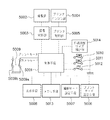
まず、基本的な撮影とプリントに関わるフローを、図9に示すブロック図と図10に示すフローチャートと図11に示す撮像装置の一具体例とを参照して説明する。撮影者が電源スイッチ2000を入力すると(ステップS2001)、制御手段5001は該装置が前回使用されて、電源がオフされてから3日以上(72時間以上)経過しているか否かを判断する(ステップS2002)。もしも3日以上経過している場合には、制御手段5001はプリンタ部の制御を受け持つプリンタ制御部5005に回復ポンピングの指示を出して、プリンタエンジン部5004を駆動する(ステップS2003)。
【0070】
ここで回復ポンピングは、後述するインクジェット記録方式のプリンタ部においてより記録を有効にするものであって、用紙への記録を行う事前に記録ヘッドを吸引ポンプ等の手段によってクリーニングするものである。このクリーニングの目安として本実施の形態においては3日間以上の未使用期間があった場合の電源入力時に、これを行うものとした。
【0071】
さて撮影者が撮影を行う場合、スイッチ5009をカメラモード5009aとするとともに、撮影モード設定手段5007を用いて撮影モードの設定を行う(ステップS2004)。本実施の形態では通常の撮影モードとポートレートモード等の数種類のモードを有する。撮影モード設定手段5007は具体的にはモード切換えスイッチ2015にて行われ、この信号が制御手段5001に伝わる。撮影者が撮影に際してズームレバー2016による画角の調整後、シャッタボタン2012を第1ストロークまで押し込むと、SW1信号5010が入力する(ステップS2005)。制御手段5001は撮像制御部5003を介して撮像部5002を駆動し、露出制御値の決定や測距情報の決定、ストロボ発光の有無等露出動作に必要な諸条件の決定を行う(ステップS2006)。撮影者が実際に撮影を実行するために、さらにシャッタボタン2012を押し込むと、制御手段5001にはSW2信号5011が入力する(ステップS2007)。
【0072】
制御手段5001は撮像制御部5003を介して撮像部5002を駆動して焦点合せのためのレンズ駆動やシャッタの速度制御、絞りの開口量制御また必要であれば、ストロボの発光等の一連の露光動作を行う(ステップS2008)。固体撮像素子1040に入力する画像情報を一時保存メモリ手段5013に取り込む(ステップS2009)。その後、制御手段5001は表示手段5008、具体的には液晶表示板2014を駆動して、撮影された画像情報を表示する(ステップS2010)。メモリ手段5013に保存されている画像データの一部を切り出して印刷するトリミング処理時には、制御手段5001は液晶表示板2014にそのトリミング領域を表示する。トリミング領域は装着されている記録用紙種と選択されているプリントスタイルとから決まるリサイズ目標値のアスペクト比と同じアスペクト比で表示することにより実際に印刷される領域を表示する。撮影動作としては、以上を繰り返すことになる。
【0073】
さて、撮影者がプリント出力を所望した場合には、スイッチ5009をプリントモード5009bとするとともに、プリント出力のモード設定をモード設定手段5006によって行う(ステップS2011)。次に、メモリ手段5013に取り込まれた画像情報を、画像送りボタン110、画像戻りボタン109によって液晶表示板2014を見ながら検索して、プリント出力したい画像情報を表示する。ここでプリントボタン2013を押すと、プリント信号PR5012が入力し、制御手段5001はプリント動作を開始する(ステップS2012)。
【0074】
制御手段5001は、印刷開始に先立ち、本体に装着されている記録用紙サイズを記録用紙サイズ検出部5014を介して検出する(ステップS2013)。制御手段5001は検出された記録用紙サイズ情報に基づいてメモリ手段5013に保存されている画像データから本体に装着されている記録用紙サイズに見合った印画データを生成するために、あらかじめ記録用紙サイズ毎に決められているリサイズ目標値にリサイズする(ステップS2014)。このリサイズ処理の内容は、前記第1の実施の形態で説明したので、ここではその詳細な説明は省略する。
【0075】
プリンタ制御部5005は記録用紙記録ヘッド400のホームポジション位置で、プリント動作をより有効にするために、まず予備吐出を行い、記録ヘッド400の目詰まりを解消したり、蒸発しているノズルを回復させたりする(ステップS2015)。
【0076】
次に、プリンタ制御部5005はメモリ手段13に蓄えられた映像情報をプリンタ出力用の画像処理を加えた上で、プリンタエンジン部5004から出力する(ステップS2016)。プリンタエンジン部5004でプリントされた印画済みプリンタ用紙1024aは、ロール状に巻かれたプリント用紙1024と切り離される位置まで自動的に給紙され、排出される(ステップS2017)。
【0077】
ここで、キャリッジHCは駆動モータ1013の正転逆転に連動して、駆動力伝達ギア1011、1010、1009を介して回転するリードスクリュー1004の螺旋溝1005に対して係合するピン(図示せず)を有し、矢印a、b方向に往復運動される。
【0078】
キャリッジHCにはインクジェットヘッドカートリッジ400が装着される。1003はガイド棒、1002は紙押さえ板であり、キャリッジの移動方向に亘って紙をプラテン1000に対して押圧する。1007、1008はフォトカプラであり、キャリッジのレバー1006のこの域での存在を確認して、モータ1013の回転方向の切替え等を行うためのホームポジション検知手段である。1016は記録ヘッドの前面をキャップするキャップ部材1022を支持する部材、1015はこのキャップ内を吸引する吸引手段であり、キャップ内開口1023を介して、記録ヘッド400の吸引回復を行う。
【0079】
1017はクリーニングブレード、1019はこのブレードを前後方向に移動可能にする部材であり、本体支持板1018にこれらは支持されている。ブレードは、この形態でなく周知のクリーニング方法が適用可能である。また、1021は吸引回復の吸引を開始するためのレバーであり、吸引手段の面1014と当接する。レバー1021はキャリッジと係合するカム1020の移動に伴って移動し、駆動モータからの駆動力がクラッチ切替え等の伝達手段で移動制御される。
【0080】
これらのキャッピング、クリーニング、吸引回復はキャリッジHCがホームポジション側領域に位置づけられたときに、リードスクリュー1005の作用によってそれらの対応位置で所望の処理が行えるように構成されているが、周知のタイミングで所望の動作を行うようにすれば、いずれにも本発明に適用することができる。
【0081】
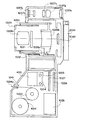
図12は、本実施の形態のプリンタ付撮像装置の中央断面の概念図である。カメラ部は沈胴型の2段式の鏡筒1029、1030について、各々撮影光学系のレンズユニット1028aおよび1028bが配置されている。1031は撮影光束を制御するとともに、露光量の制御を兼用する絞りユニットであり、同じく鏡筒1029に配置されている。1032は鏡筒1030を回動させるヘリコイド部材であり、鏡筒1030のカム凸部1030aと係合している。該ヘリコイド部材1032は図示しないヘリコイド駆動モータによって駆動される。上述した撮影光学系1028aおよび1028b、ならびにシャッタユニット1031を通った光束は、固体撮像素子1040上に結像する。
【0082】
1037a、1037b、1037c、1037d、1037eはファインダを構成する光学系レンズである。これらのうち1037b、1037c、1037dは撮影光学系の画角調整(ズーム操作)に伴って移動し、撮影光学系の画角と略同じ画角を確認することができる。この光学式ファインダは画像表示用の液晶表示板2014を用いることで、電力が消費されるのを防ぐ場合等に有効である。
【0083】
絞りユニット1031は固体撮像素子(CCD)1040の露出量をフィードバック制御によって適正に保つように駆動される。撮像された信号は、画像処理基板1026で処理される。処理された信号はプリンタ制御基板1027へ送出され、プリンタ部のインクジェットヘッドカートリッジ400の位置制御信号等の情報と合わせて、印刷動作に必要な駆動モータ等へ伝達される。
【0084】
プリント動作はプリントボタン2013によって開始され、ロール状に巻かれたプリンタ用紙1024からプラテン1000を介して、プリント用紙1024aが引き出されて印刷される。この記録用紙1024は少なくとも2種以上のサイズを装着することが可能である。1041は外装カバーで形成された紙カッタ部であり、印刷後のプリント用紙1024aを切り離すのに用いられる。1025は電源である。
【0085】
インクジェット記録方式の中でもインク吐出を行わせるために利用されるエネルギとして、熱エネルギを発生する手段(例えば電気熱変換体やレーザ光等)を備え、熱エネルギによりインクの状態変化を生起させる方式の記録ヘッド、記録装置の代表的な構成や原理については、例えば米国特許第4723129号明細書、同第4740796号明細書に開示されている基本的な原理を用いて行うのものが好ましい。この方式は特にオンデマンド型の場合には、液体(インク)が保持されているシートや液路に対して配置されている電気熱変換体に、記録情報に対応していて膜沸騰を越える急速な温度上昇を与える少なくとも1つの駆動信号を印加する。これによって電気熱変換体に熱エネルギを発生させ、記録ヘッドの熱作用面に膜沸騰させて、結果的にこの駆動信号に一対一対応し液体(インク)内の気泡を形成できるので有効である。
【0086】
この気泡の成長、収縮により、吐出用開口を介して液体(インク)を吐出させて、少なくとも1つの滴を形成する。この駆動信号をパルス形状とすると、即時適切に気泡の成長収縮が行われるので、特に応答性に優れた液体(インク)の吐出が達成できるため、より好ましい。このパルス形状の駆動信号としては、米国特許第4463359号明細書、同第4345262号明細書に記載されているものが適している。なお、前記熱作用面の温度上昇率に関する発明の米国特許第4313124号明細書に記載されている条件を採用すると、さらに優れた記録を行うことができる。
【0087】
記録ヘッドの構成としては、上述の各明細書に開示されているような吐出口、液路、電気熱変換体の組み合わせ構成(直線状液路または直角液流路)の他に熱作用部が屈曲する領域に配置されている構成を開示する米国特許第4558333号明細書、米国特許4459600号明細書を用いた構成も本発明に含まれるものである。
【0088】
加えて、複数の電気熱変換体に対して、共通するスリットを電気熱変換体の吐出部とする構成を開示する特開昭59−123670号公報や、熱エネルギの圧力波を吸収する開孔を吐出部に対応させる構成を開示する特開昭59−138461号公報に基づいた構成としても本発明は有効である。
【0089】
さらに、記録装置部が記録できる最大記録媒体の幅に対応した長さを有するフルラインタイプの記録ヘッドとしては、上述した明細書に開示されているような複数記録ヘッドの組み合わせによって、その長さを満たす構成や、一体的に形成された1個の記録ヘッドとしての構成のいずれかでもよい。これらの構成をとることで本発明をいっそう有効に発揮することができる。
【0090】
加えて、装置本体に装着されることで、装置本体との電気的な接続や装置本体からのインクの供給が可能になる交換自在のチップタンクの記録ヘッド、あるいは記録ヘッド自体に一体的に設けられたカートリッジタイプの記録ヘッドを用いた場合にも本発明は有効である。また、本発明の記録装置部の構成として設けられている記録ヘッドに対しての回復手段、予備的な補助手段等を付加することは、本発明の効果をさらに安定できるので好ましい。
【0091】
これらを具体的に挙げれば、記録ヘッドに対してのキャッピング手段、クリーニング手段、加圧あるいは吸引手段、電気熱変換体あるいはこれとは別の加熱素子、あるいはこれらの組み合わせによる予備加熱手段、記録とは別に吐出を行う予備吐出モードを行うことも安定した記録を行うために有効である。さらに記録装置部の記録モードとしては、黒色等の主流色のみの記録だけではなく、記録ヘッドを一体的に構成するか複数個の組み合わせによってでもよいが、異なる色の複色カラーまたは混色によるフルカラーの少なくとも1つを備えた装置であることが極めて有効になる。
【0092】
(その他の実施の形態)
上述した実施の形態の機能を実現するべく各種のデバイスを動作させるように、該各種デバイスと接続された装置或いはシステム内のコンピュータに対し、前記実施の形態の機能を実現するためのソフトウェアのプログラムコードを供給し、そのシステム或いは装置のコンピュータ(CPU或いはMPU)に格納されたプログラムに従って前記各種デバイスを動作させることによって実施したものも、本発明の範疇に含まれる。
【0093】
また、この場合、前記ソフトウェアのプログラムコード自体が上述した実施の形態の機能を実現することになり、そのプログラムコード自体は本発明を構成する。そのプログラムコードの伝送媒体としては、プログラム情報を搬送波として伝搬させて供給するためのコンピュータネットワーク(LAN、インターネット等のWAN、無線通信ネットワーク等)システムにおける通信媒体(光ファイバ等の有線回線や無線回線等)を用いることができる。
【0094】
さらに、前記プログラムコードをコンピュータに供給するための手段、例えばかかるプログラムコードを格納した記録媒体は本発明を構成する。かかるプログラムコードを記憶する記録媒体としては、例えばフレキシブルディスク、ハードディスク、光ディスク、光磁気ディスク、CD−ROM、磁気テープ、不揮発性のメモリカード、ROM等を用いることができる。
【0095】
また、コンピュータが供給されたプログラムコードを実行することにより、上述の実施の形態の機能が実現されるだけでなく、そのプログラムコードがコンピュータにおいて稼働しているOS(オペレーティングシステム)或いは他のアプリケーションソフト等と共同して上述の実施の形態の機能が実現される場合にもかかるプログラムコードは本発明の実施の形態に含まれることはいうまでもない。
【0096】
さらに、供給されたプログラムコードがコンピュータの機能拡張ボードやコンピュータに接続された機能拡張ユニットに備わるメモリに格納された後、そのプログラムコードの指示に基づいてその機能拡張ボードや機能拡張ユニットに備わるCPU等が実際の処理の一部又は全部を行い、その処理によって上述した実施の形態の機能が実現される場合にも本発明に含まれることはいうまでもない。
【0097】
なお、前記実施の形態において示した各部の形状及び構造は、何れも本発明を実施するにあたっての具体化のほんの一例を示したものに過ぎず、これらによって本発明の技術的範囲が限定的に解釈されてはならないものである。すなわち、本発明はその精神、又はその主要な特徴から逸脱することなく、様々な形で実施することができる。
【0098】
【発明の効果】
以上述べたように本発明によれば、記録用紙種、プリントスタイル毎にリサイズ目標値を変えることによって、その記録用紙に最適な印刷サイズのプリントデータが生成されるのでユーザにとって使い勝手に優れている。
【0099】
また、トリミング処理時に画像切り出し枠を記録用紙種、プリントスタイル毎にそのリサイズ目標値のアスペクト比と同じアスペクト比に設定することによって記録用紙サイズに見合ったプリントデータを生成することができる。
【0100】
また、トリミング領域を記録用紙、プリントスタイル毎に各々のリサイズ目標値のアスペクト比と同じ枠を電子ビューファインダ等の表示手段上に表示することによってトリミング領域を視覚的にユーザが認識できるようになる。
【図面の簡単な説明】
【図1】本発明の第1の実施形態における構成を示す図である。
【図2】本発明の第1の実施形態における動作のフローチャートである。
【図3】本発明の第1の実施形態における用紙を示す図である。
【図4】本発明の第1の実施形態における結線状態を示す図である。
【図5】本発明の第1の実施形態における動作のフローチャートである。
【図6】本発明の第1の実施形態における動作のフローチャートである。
【図7】本発明の第2の実施形態におけるブロック図である。
【図8】本発明の第2の実施形態における動作のフローチャートである。
【図9】本発明の第2の実施形態における構成概要を示す図である。
【図10】本発明の第2の実施形態における動作のフローチャートである。
【図11】本発明の第2の実施形態における構成概要を示す図である。
【図12】本発明の第2の実施形態における構成の中央断面図である。
【符号の説明】
1 装置本体
2 用紙カセット
3 給紙ローラ
4 搬送ローラ対
5 プラテンローラ
6 サーマルヘッド
7 インクカセット
8 インクシート
9a 排紙ローラ
9b 排紙ローラ
10 記録紙先端検出センサ
11 SW2信号
12 ミシン目
13 一時保存画像メモリ手段
14 印字情報メモリ手段
41 グリップローラ
42 ピンチローラ
15 ガイド部
16 余白部
17 印画領域
18 処理回路
19 制御手段
20 バネ
21 押上げ板
22 ヘッドアーム
23 ヘッドカバーA
24 ヘッドカバーB
25 用紙搬送ガイド部
26 排紙トレイ部
27 ケーブル
DC デジタルカメラ[0001]
BACKGROUND OF THE INVENTION
The present invention relates to a printing system, an imaging device, and an imaging system using a thermal transfer recording printer or an inkjet recording printer. Bip How to output lint To the law More specifically, the present invention relates to a print system suitable for printing out an image captured by an imaging device such as a still camera or a video camera that records a still image.
[0002]
[Prior art]
Conventionally, heat-sensitive paper has been used as printing paper, and a plurality of heating elements arranged in the main scanning direction are selectively driven to convey the paper in the sub-scanning direction, thereby printing dots on the paper. There is a printer of the line thermal transfer recording system that performs this.
[0003]
2. Description of the Related Art In recent years, with the progress of input devices that handle images such as digital cameras, digital video cameras, and scanners on the input side, thermal transfer recording type printer apparatuses have attracted attention as printer means. The reason is that the ink jet printer has only two choices of whether or not to drop the droplets, so that small droplets are landed on the paper and an apparent resolution and gradation are obtained by techniques such as error diffusion. On the other hand, in the case of a thermal transfer recording type printer, the heat value that can be controlled in one pixel can be easily changed, so that a large gradation can be obtained for one pixel. As compared with an ink jet printer, a smoother and higher quality image can be obtained.
[0004]
In addition, since the performance of the thermal head and the performance of the paper material have been improved, it is possible to obtain an image print that has a finished quality and is not inferior to a silver halide photograph. In order to keep pace with the recent progress of digital cameras, it is attracting attention as a printer for natural images. In addition, the ink jet printer has been further miniaturized, and it has become possible to output a high-quality image that is substantially inferior to the thermal transfer recording method.
[0005]
Therefore, such a printer device and an imaging device such as a digital camera or a digital video camera are directly connected or integrally configured, and the captured image information is passed through a device such as a computer for processing the image information. There is also a system that prints without any problems. According to these systems, it is possible to easily print out image information from a digital camera or a digital video, which is very convenient.
[0006]
As an example of these, for example, Japanese Patent Application Laid-Open No. 10-243327 describes connection between an image input device and an image output device. According to this, an image input / output system in which an image output device and an image input device are connected, the image output device receives and outputs an image signal from the image input device, and A power supply unit for supplying power is included. In addition, the image input device is connected to the image output device by a connection cable for transmitting image data to the image output device and receiving power supply from the image output device, and whether or not power can be received from the image output device. And a power supply unit.
[0007]
When the determination unit determines that the power supply from the image output device can be received, the power from the image output device is used. When the determination unit determines that the power supply cannot be received, the power from the power supply unit is used. It is to use. According to this, since power is supplied from the image output device, it is extremely effective because print output can be performed without worrying about the remaining power of the image input device such as a digital camera.
[0008]
Japanese Patent Application Laid-Open No. 9-65182 describes power saving during printing. According to this, a composite camera is described which has an electronic viewfinder and integrates a photographing means for recording video information on a recording medium and a printer means for printing out the video information on recording paper. Control means is provided for controlling to stop supplying power to the electronic viewfinder while the printer means prints out the video information on the recording paper. According to this, since power is not supplied to the electronic viewfinder during printing, it is useful for power saving and is extremely effective.
[0009]
[Problems to be solved by the invention]
By the way, in a general printer apparatus, since the size to be printed and the recording paper size are specified independently, there is a problem that printing is not performed with a size suitable for the recording paper.
[0010]
Even in the system of the printer device and the imaging device such as a digital camera described in the conventional example, when there are a plurality of types of recording paper that can be handled by the printer, the image information from the imaging device is obtained depending on the recording paper type. It is more convenient to resize (enlarge or reduce the image) to a size suitable for the recording paper.
[0011]
If there is a function to cut out and print a part of the image stored in the imaging device, the area printed on the electronic viewfinder is surrounded by a frame for each recording paper loaded in the printer device. When displayed, it is convenient for the user to visually recognize the area to be printed.
[0012]
The present invention takes the above-mentioned problems into consideration, and even if there are a plurality of types of recording papers and the print style can be selected, it is possible to generate optimal print data and achieve good results. The purpose is to enable print output.
[0013]
[Means for Solving the Problems]
The printing system of the present invention is connected to an imaging device that converts an optical image of a scene to be photographed into image information, and a printer device that prints out an image captured by the imaging device so as to be visible on a recording sheet. Printing system, The setting means that sets either the borderless printing mode that does not leave margins in the paper or the bordered printing mode that leaves margins in the paper before the print execution instruction and the print execution instruction are input. In response, an acquisition unit that acquires information about the paper loaded in the printer device, a paper size acquired by the acquisition unit, and a print mode set by the setting unit, the image to be printed is resized. Based on the target size setting means for setting a target size to be set when performing the resizing, calculating the resizing ratio so as to be the target size, resizing the image to be printed, and the image resized by the resizing means Print data generation means for generating print data, and the target size setting means uses the setting means to perform borderless print mode. Is set to a size larger than the paper size, and when the bordered print mode is set by the setting unit, the target size is set to a size smaller than the paper size, The resizing unit sets the horizontal size of the image to be printed to Xi, the vertical size to Yi, the horizontal size of the paper loaded in the printer device to Xp, the vertical size to Yp, and the target size. Yi / Yt and Xi / Xt are calculated assuming that Xt is the horizontal size and Yt is the vertical size. If the borderless printing mode is set, Yi / Yt or Xi / Xt Is selected as the resizing ratio, and when the bordered printing mode is set, the larger of Yi / Yt or Xi / Xt is resized. A resizing ratio selecting means for selecting as follows, and when the aspect ratio of the image to be printed and the aspect ratio of the target size are Yi / Xi> Yt / Xt, the horizontal direction when the borderless printing mode is set When the print mode with margin is set as the reference, it is determined as the vertical direction reference, and when the aspect ratio of the image to be printed and the aspect ratio of the target size are Yi / Xi <Yt / Xt The resize ratio selection unit includes a reference determining unit that determines the vertical reference when the borderless printing mode is set, and determines the horizontal reference when the bordered printing mode is set. The image to be printed is resized based on the resizing rate selected by the means and the reference determined by the reference determining means. Characterized by points.
[0014]
An image pickup apparatus according to the present invention includes an image pickup unit that converts an optical image of a field to be shot into image information, and prints out an image picked up by the image pickup unit so as to be visible on a recording sheet. apparatus An imaging device capable of communicating with The setting means that sets either the borderless printing mode that does not leave margins in the paper or the bordered printing mode that leaves margins in the paper before the print execution instruction and the print execution instruction are input. In response, an acquisition unit that acquires information about the paper loaded in the printer device, a paper size acquired by the acquisition unit, and a print mode set by the setting unit, the image to be printed is resized. Based on the target size setting means for setting a target size to be set when performing the resizing, calculating the resizing ratio so as to be the target size, resizing the image to be printed, and the image resized by the resizing means Print data generation means for generating print data, and the target size setting means uses the setting means to perform borderless print mode. Is set to a size larger than the paper size, and when the bordered print mode is set by the setting unit, the target size is set to a size smaller than the paper size, The resizing unit sets the horizontal size of the image to be printed to Xi, the vertical size to Yi, the horizontal size of the paper loaded in the printer device to Xp, the vertical size to Yp, and the target size. Yi / Yt and Xi / Xt are calculated assuming that Xt is the horizontal size and Yt is the vertical size. If the borderless printing mode is set, Yi / Yt or Xi / Xt Is selected as the resizing ratio, and when the bordered printing mode is set, the larger of Yi / Yt or Xi / Xt is resized. A resizing ratio selecting means for selecting as follows, and when the aspect ratio of the image to be printed and the aspect ratio of the target size are Yi / Xi> Yt / Xt, the horizontal direction when the borderless printing mode is set When the print mode with margin is set as the reference, it is determined as the vertical direction reference, and when the aspect ratio of the image to be printed and the aspect ratio of the target size are Yi / Xi <Yt / Xt The resize ratio selection unit includes a reference determining unit that determines the vertical reference when the borderless printing mode is set, and determines the horizontal reference when the bordered printing mode is set. The image to be printed is resized based on the resizing rate selected by the means and the reference determined by the reference determining means. Characterized by points.
[0015]
According to the print output method of the present invention, an image picked up by an image pickup device is recorded. Depending on the printer device A print output method for printing on a recording sheet so as to be visible, The setting procedure for setting either the borderless printing mode that leaves no margin in the paper or the bordered printing mode that leaves the margin in the paper before the print execution instruction and the print execution instruction are input. Accordingly, the image to be printed is resized in accordance with the acquisition procedure for acquiring information about the paper loaded in the printer device, the paper size acquired by the acquisition procedure, and the print mode set by the setting procedure. Based on the target size setting procedure for setting the target size when performing the resize, calculating the resizing ratio so as to be the target size, resizing the image to be printed, and the image resized by the resizing procedure A print data generation procedure for generating print data, and in the target size setting procedure, a borderless print mode is set by the setting procedure. When the print mode is set, the target size is set to a size larger than the paper size. When the bordered print mode is set by the setting procedure, the target size is set to a size smaller than the paper size. In the resizing procedure, the horizontal size of the image to be printed is Xi, the vertical size is Yi, the horizontal size of the paper loaded in the printer device is Xp, the vertical size is Yp, and the target If the horizontal size of the size is Xt and the vertical size is Yt, Yi / Yt and Xi / Xt are calculated. If the borderless printing mode is set, Yi / Yt or Xi / Xt If the smaller one is selected as the resizing ratio and the bordered printing mode is set, the larger one of Yi / Yt or Xi / Xt is selected as the resizing ratio. If the aspect ratio of the image to be printed and the aspect ratio of the target size are Yi / Xi> Yt / Xt and the borderless printing mode is set, It is determined as a horizontal reference, and when the bordered printing mode is set, it is determined as a vertical reference, and the aspect ratio of the image to be printed and the aspect ratio of the target size are Yi / Xi <Yt / Xt. A reference determination procedure for determining a vertical reference when the borderless print mode is set, and determining a horizontal reference when the border print mode is set, and the resizing Resizing the image to be printed based on the resizing rate selected in the rate selection procedure and the criteria determined in the criteria determination procedure Characterized by points.
[0019]
DETAILED DESCRIPTION OF THE INVENTION
Hereinafter, embodiments of a print system, an imaging apparatus, a print output method, a program, and a computer-readable storage medium according to the present invention will be described with reference to the drawings.
[0020]
(First embodiment)
Hereinafter, the first embodiment will be described with reference to FIGS. In the printing system of this embodiment, a printer device of a sublimation type thermal transfer recording system is adopted as the printer means, and electronic image information can be printed out for an arbitrary number of prints. The printing system will be described according to the procedure.
[0021]
An example of a thermal transfer recording type printer apparatus will be specifically described with reference to the drawings. FIG. 1 is a schematic configuration diagram of a side surface of a printer apparatus. First, the overall configuration of the printer apparatus will be described. The recording paper P is separated and fed to the apparatus
[0022]
In the recording unit, the
[0023]
The ink sheet covers the print area of the recording paper P and is provided with a yellow (Y), magenta (M), and cyan (C) ink layer and an overcoat (OP) layer arranged in a size substantially equal to the size. After each layer is thermally transferred, the recording paper P is returned to the recording start position, and sequentially transferred onto the recording paper. In this way, the recording paper P is reciprocated by the number of inks of each color and the number of overcoat layers by the conveying
[0024]
At this time, the recording paper P after printing of each ink layer is reversed in front of the apparatus
[0025]
[0026]
After the printing of each ink layer is completed, the recording paper P is guided to the
[0027]
Further, the
[0028]
Since the thermal transfer recording type printer apparatus records the three colors of YMC three times sequentially, it is necessary to control to accurately match the recording leading ends of the respective colors. For this purpose, it is necessary to carry the paper while firmly holding the recording paper P without separating it with the pair of carrying
[0029]
In this embodiment, the recording paper P having the
[0030]
Further details regarding the printer apparatus will be described below. In the printer apparatus shown in FIG. 1, the conveying
[0031]
As an example, the recording pitch for one line by the
[0032]
In the printer apparatus shown in FIG. 1, a recording paper leading
[0033]
In the apparatus
[0034]
In the flowchart of FIG. 2, the color ink transfer and overcoat sequence will be described.
Step S1: The user instructs a print operation by a print button (not shown) or a print instruction from a digital camera or digital video camera.
Step S2: The processing
[0035]
Step S3: When printing preparation is completed, the control means constituted by the CPU or the like drives the motor connected to the
Step S4: After detecting the leading edge of the recording paper P, the stepping motor is rotated by a predetermined step to start printing. At this time, the printing start position was 12.465 mm with reference to the leading edge of the recording paper.
Step S5: Subsequently, while the stepping motor is rotated by 4 steps, the thermal head is driven to generate heat and printing for one line is performed. The printing is completed by rotating for a total of 6776 steps (1694 lines). The print end position at this time is 156.455 mm with respect to the leading edge of the recording paper.
[0036]
Step S6: Next, the stepping motor is rotated by 10 lines (40 steps) and stopped for deceleration until it stops.
Step S7: From this state, the stepping motor is driven in the reverse direction to transport the recording paper P in the reverse direction to the time of printing. It is returned by a predetermined number of steps (6776 step deceleration), and further rotated for 10 lines (40 steps) of a predetermined number of lines for deceleration.
[0037]
Step S8: The above operation is repeated three times for the three colors of YMC, and a desired mark image is transferred and recorded on the recording paper P.
Step S9: Thereafter, the overcoat layer for protecting the seal screen is transferred once more.
Step S10: Thereafter, the stepping motor is driven in the reverse direction and guided to the
[0038]
Further, in the above description, when the recording paper P is fed, the control means determines the number of steps of the stepping motor and the position when the recording paper P is conveyed based on the recording paper leading edge detection signal first detected by the recording paper leading
[0039]
In the above description, the transfer of the overcoat layer is described to be performed only by turning ON / OFF the heat drive of the thermal head. However, at the start of the overcoat transfer, the heat generation amount is gradually increased and the overcoat transfer is performed. At the end, it is also possible to add control that is obtained by gradually decreasing the heat generation amount.
[0040]
Now, the contents related to the present invention will be described in more detail. The communication between the device that executes the print instruction in step S2 and the printer device will be described in more detail. As an example, it is assumed that the print instruction is executed as a digital camera DC.
[0041]
FIG. 4 is a schematic diagram in which the digital camera DC and the apparatus
[0042]
Now, it is assumed that a mode of the digital camera DC is set and an arbitrary image is reproduced. Since the reproduction of the image information can be confirmed at any time by the liquid crystal display device provided in the digital camera DC, the user can arbitrarily call up the photographed favorite image information.
[0043]
When the
[0044]
The necessary information includes information on negotiation with the digital camera DC, information on an image to be printed from the digital camera DC, information added to the image information at or after recording, and the like.
[0045]
FIG. 5 is a flowchart showing the printing operation in the present embodiment. When the execute button is pressed (step S501), the type of recording paper loaded in the printer is detected and transmitted to the digital camera DC (step S502). Receiving this recording paper information, the digital camera DC distributes resizing processing steps S506 to S508 for each recording paper size in order to resize the recording paper to a size corresponding to the recording paper size (steps S503 to S505). If a recording paper size not supported by the digital camera DC is designated from the printer, it is processed as an error and printing is not performed (step S509).
[0046]
The image data subjected to the resizing process in each of steps S506 to S508 is processed and generated as print data, and transmitted to the printer device for printing (step S510).
[0047]
Here, the resizing process executed in steps S506 to S508 will be described in detail. When resizing the image data stored in the digital camera DC to the size of the recording paper installed in the printer device, the resize target value depends on whether printing is performed with margins to leave margins in the recording paper or borderless printing with full printing. Will change. The designation of borderless printing and bordered printing is set by the user as a print style before printing.
[0048]
With reference to FIG. 6, the difference in the resize target value between the bordered printing and the borderless printing will be described. FIG. 6A illustrates the relationship between the recording paper sizes Xpaper and Ypaper and the resize target values Xtarget and Ytarget during borderless printing. Since this is borderless printing, the resize target value is set larger than the recording paper size so that no margins remain during printing.
[0049]
FIG. 6B illustrates the relationship between vertical and horizontal recording paper sizes Xpaper and Ypaper and vertical and horizontal resize target values Xtarget and Ytarget during bordered printing. Since printing is performed with margins, the resize target value is set to be smaller than the recording paper size so that margins remain during printing.
[0050]
As described above, the resize target value varies depending on the print style. However, since the resize target value also varies depending on the recording paper size, the resize target value for all the recording paper sizes and print styles handled by the printer device is set in advance in the digital camera. It is prepared for DC.
[0051]
In the present embodiment, the three sizes from 1 to 3 are handled. However, the number of paper types is not limited as long as the resize target values corresponding to the recording paper types to be handled are provided.
[0052]
Next, referring to FIG. 7, in FIGS. 7A to 7D, marginless printing that does not leave a margin on the recording paper, and in FIGS. 7E to 7H, printing with margin that leaves a margin on the recording paper. A resizing method will be described.
[0053]
The meaning of the symbols in FIG.
Ximg Image size before horizontal resizing
Yimg Image size before resizing in the vertical direction
Xpaper Horizontal recording paper size
Ypaper Vertical recording paper size
Xtarget Horizontal resize target value
Ytarget Vertical resize target value
It is.
[0054]
(For borderless printing)
In the case of borderless printing, no margin is created in the recording paper. Therefore, as described in FIG. 6, Ypaper <Ytarget, Xpaper <Xtarget, and enlargement is based on the smaller direction of Yimg / Ytarget or Ximg / Xtarget. Alternatively, a reduction rate (resizing rate) is selected.
[0055]
FIG. 7A shows a case where the aspect ratio Yimg / Ximg of the image data stored in the digital camera DC is larger than the aspect ratio Ytarget / Xtarget of the resize target value. in this case,
Yimg / Ximg> Ytarget / Xtarget
Yimg / Ytarget> Ximg / Xtarget
Ytarget <Yimg * Xtarget / Ximg
And resize on a horizontal basis (X basis).
[0056]
When resizing on the X basis, the vertical direction (Y direction) becomes larger than the resize target value Ytarget, so the vertical image data is cut to match the resize target value Ytarget, and image data as shown in FIG. Is generated.
[0057]
FIG. 7C shows a case where the aspect ratio Yimg / Ximg of the image data stored in the digital camera DC is smaller than the aspect ratio Ytarget / Xtarget of the resize target value. in this case,
Yimg / Ximg <Ytarget / Xtarget
Yimg / Ytarget <Ximg / Xtarget
Xtarget <Ximg * Ytarget / Yimg
And resizing in the vertical direction standard (Y standard).
[0058]
When resizing on the Y basis, the horizontal direction (X direction) becomes larger than the resize target value Xtarget, so the image data in the horizontal direction is cut to match the resize target value Xtarget, and image data as shown in FIG. Is generated.
[0059]
(For bordered printing)
In the case of bordered printing, the resize target value is a value that fits all areas of the image data stored in the digital camera DC within the recording paper sizes Ypaper and Xpaper. Ypaper> Ytarget, Xpaper> Xtarget, and the resize ratio is selected based on the larger direction of Yimg / Ytarget or Ximg / Xtarget.
[0060]
FIG. 7E shows a case where the aspect ratio Yimg / Ximg of the image data stored in the digital camera DC is larger than the aspect ratio Ytarget / Xtarget of the resize target value. in this case,
Yimg / Ximg> Ytarget / Xtarget
Yimg / Ytarget> Ximg / Xtarget
Therefore, when the image is resized in the vertical direction reference (Y reference), image data as shown in FIG. 7F is generated.
[0061]
FIG. 7G shows a case where the aspect ratio Yimg / Ximg of the image data stored in the digital camera DC is smaller than the aspect ratio Ytarget / Xtarget of the resize target value. in this case,
Yimg / Ximg <Ytarget / Xtarget
Yimg / Ytarget <Ximg / Xtarget
Therefore, when resizing is performed on the basis of the horizontal direction (X standard), image data as shown in FIG. 7H is generated.
[0062]
The resizing process has been described above. Next, the resizing process at the time of the trimming process for cutting out and printing a part of the image data stored in the digital camera DC will be described with reference to FIG. FIG. 8A shows image data stored in the digital camera DC.
[0063]
FIG. 8B shows image data obtained by cutting out a part from the image data shown in FIG. 8A with frames of Ximgwindow1 and Yimgwindow1 and resizing them to resize target values Xtarget and Ytarget.
[0064]
FIG. 8C shows image data obtained by cutting out a part of the image data shown in FIG. 8A with the frames of Ximgwindow2 and Yimgwindow2 and resizing them to the same resize target values Xtarget and Ytarget as in FIG. 8B.
[0065]
The aspect ratio of the image cutout frame in FIG.
Yimgwindow1 / Ximgwindow1 = Yimgwindow2 / Ximgwindow2
There is a relationship.
[0066]
FIGS. 8B and 8C show that the magnification of the image resized to Xtarget and Ytarget changes by changing the size while maintaining the aspect ratio of the image clipping frame, and can be arbitrarily set. Yes. In the trimming process, the resize target value is uniquely determined from the type of recording paper loaded in the printer and the set print style. Therefore, if the image cropping frame size is Ximgwindow or Yimgwindow, the aspect ratio of the image cropping frame Is set to be the same as the aspect ratio Yimgwindow / Ximgwindow of the resize target value, the condition judgment as described in FIG.
Xtarget / Ximgwindow = Ytarget / Yimgwindow
It becomes. If this image clipping frame is displayed on the electronic viewfinder of the digital camera DC during the trimming process, the user can visually confirm the trimming area, which is very convenient. The trimming designation is performed by the user before executing printing together with the above-described bordered printing and bordered printing selection.
[0067]
(Second Embodiment)
Hereinafter, a second embodiment of the present invention will be described with reference to the drawings. In addition, the same code | symbol is attached | subjected to the component same as 1st Embodiment, and the detailed description is abbreviate | omitted. The second embodiment is an example in which an image pickup apparatus such as a digital camera is integrally provided with a printer unit. In such an imaging apparatus with a printer, it is possible to perform printing immediately on the spot according to shooting. Hereinafter, it is assumed that the apparatus has at least two types of recording paper that can be handled.
[0068]
The image pickup apparatus according to the present embodiment employs an ink jet recording method in the printer unit, stores electronic image pickup in a memory, and prints out video information stored in an arbitrary memory for an arbitrary number of prints. It can be done.
[0069]
First, a flow related to basic photographing and printing will be described with reference to a block diagram shown in FIG. 9, a flowchart shown in FIG. 10, and a specific example of the imaging apparatus shown in FIG. When the photographer inputs the power switch 2000 (step S2001), the
[0070]
Here, the recovery pumping is to make recording more effective in a printer unit of an ink jet recording method to be described later, and to clean the recording head by means such as a suction pump before recording on paper. As a guideline for this cleaning, in the present embodiment, this is performed at the time of power input when there is an unused period of 3 days or more.
[0071]
When the photographer performs photographing, the
[0072]
The
[0073]
If the photographer desires print output, the
[0074]
Prior to the start of printing, the
[0075]
In order to make the printing operation more effective at the home position of the recording
[0076]
Next, the
[0077]
Here, the carriage HC is engaged with a
[0078]
The
[0079]
[0080]
These capping, cleaning, and suction recovery are configured so that when the carriage HC is positioned in the home position side region, desired processing can be performed at the corresponding positions by the action of the
[0081]
FIG. 12 is a conceptual diagram of a central section of the imaging apparatus with a printer according to the present embodiment. In the retractable two-
[0082]
[0083]
The
[0084]
The printing operation is started by a
[0085]
Among the ink jet recording methods, a method for generating thermal energy (for example, an electrothermal converter, a laser beam, etc.) as energy used for ejecting ink, and causing a change in the state of the ink by the thermal energy. As for the typical configuration and principle of the recording head and the recording apparatus, it is preferable to use the basic principle disclosed in, for example, US Pat. Nos. 4,723,129 and 4,740,796. In particular, in the case of the on-demand type, this method corresponds to the recording information on the sheet that holds the liquid (ink) and the electrothermal transducer disposed on the liquid path, and rapidly exceeds the film boiling. Apply at least one drive signal that provides a reasonable temperature rise. This is effective because heat energy is generated in the electrothermal transducer and the film is boiled on the heat acting surface of the recording head. As a result, bubbles in the liquid (ink) can be formed in one-to-one correspondence with the drive signal. .
[0086]
By the growth and contraction of the bubbles, the liquid (ink) is ejected through the ejection opening to form at least one droplet. It is more preferable that the drive signal has a pulse shape, since the bubble growth and contraction is performed immediately and appropriately, and thus liquid (ink) discharge having particularly excellent responsiveness can be achieved. As the pulse-shaped drive signal, those described in US Pat. Nos. 4,463,359 and 4,345,262 are suitable. Further excellent recording can be performed by employing the conditions described in US Pat. No. 4,313,124 of the invention relating to the temperature rise rate of the heat acting surface.
[0087]
As the configuration of the recording head, in addition to the combination configuration (straight liquid path or right-angle liquid flow path) of the discharge port, liquid path, and electrothermal transducer as disclosed in each of the above-mentioned specifications, Configurations using US Pat. No. 4,558,333 and US Pat. No. 4,459,600, which disclose configurations disposed in the bending region, are also included in the present invention.
[0088]
In addition, for a plurality of electrothermal transducers, Japanese Patent Application Laid-Open No. 59-123670 that discloses a configuration in which a common slit is used as a discharge portion of the electrothermal transducer, or an aperture that absorbs pressure waves of thermal energy The present invention is also effective as a configuration based on Japanese Patent Application Laid-Open No. 59-138461 which discloses a configuration in which the nozzle is made to correspond to the discharge section.
[0089]
Furthermore, as a full-line type recording head having a length corresponding to the maximum recording medium width that can be recorded by the recording apparatus unit, a combination of a plurality of recording heads as disclosed in the above specification can be used. Either a configuration satisfying the above or a configuration as a single recording head formed integrally may be used. By taking these configurations, the present invention can be more effectively exhibited.
[0090]
In addition, it can be attached to the main body of the device so that it can be electrically connected to the main body of the device and supplied with ink from the main body of the device. The present invention is also effective when a cartridge type recording head is used. In addition, it is preferable to add recovery means, preliminary auxiliary means, and the like for the recording head provided as the configuration of the recording apparatus unit of the present invention, since the effects of the present invention can be further stabilized.
[0091]
Specifically, capping means for the recording head, cleaning means, pressurizing or suction means, electrothermal converter or a heating element different from this, or preheating means by a combination thereof, recording and In addition, it is also effective to perform a preliminary ejection mode in which ejection is performed separately in order to perform stable recording. Furthermore, as a recording mode of the recording apparatus unit, not only recording of mainstream colors such as black, but also a recording head may be configured integrally or a plurality of combinations may be used. It is extremely effective that the apparatus has at least one of the following.
[0092]
(Other embodiments)
A software program for realizing the functions of the above-described embodiments for a computer in an apparatus or a system connected to the various devices so as to operate the various devices to realize the functions of the above-described embodiments. What is implemented by supplying a code and operating the various devices according to a program stored in a computer (CPU or MPU) of the system or apparatus is also included in the scope of the present invention.
[0093]
In this case, the program code of the software itself realizes the functions of the above-described embodiments, and the program code itself constitutes the present invention. As a transmission medium for the program code, a communication medium (wired line or wireless line such as an optical fiber) in a computer network (LAN, WAN such as the Internet, wireless communication network, etc.) system for propagating and supplying program information as a carrier wave Etc.) can be used.
[0094]
Further, means for supplying the program code to the computer, for example, a recording medium storing the program code constitutes the present invention. As a recording medium for storing the program code, for example, a flexible disk, a hard disk, an optical disk, a magneto-optical disk, a CD-ROM, a magnetic tape, a nonvolatile memory card, a ROM, or the like can be used.
[0095]
Further, by executing the program code supplied by the computer, not only the functions of the above-described embodiments are realized, but also the OS (operating system) or other application software in which the program code is running on the computer. Needless to say, the program code is also included in the embodiment of the present invention even when the functions of the above-described embodiment are realized in cooperation with the above.
[0096]
Further, after the supplied program code is stored in the memory provided in the function expansion board of the computer or the function expansion unit connected to the computer, the CPU provided in the function expansion board or function expansion unit based on the instruction of the program code Needless to say, the present invention also includes the case where the functions of the above-described embodiment are realized by performing part or all of the actual processing.
[0097]
It should be noted that the shapes and structures of the respective parts shown in the above-described embodiments are merely examples of implementation in carrying out the present invention, and these limit the technical scope of the present invention. It should not be interpreted. That is, the present invention can be implemented in various forms without departing from the spirit or main features thereof.
[0098]
【The invention's effect】
As described above, according to the present invention, by changing the resize target value for each recording paper type and print style, print data having an optimum print size for the recording paper is generated, which is excellent for the user. .
[0099]
In addition, print data corresponding to the recording paper size can be generated by setting the image cutout frame to the same aspect ratio as the resize target value for each recording paper type and print style during the trimming process.
[0100]
In addition, the trimming area can be visually recognized by the user by displaying on the display means such as an electronic viewfinder the frame having the same aspect ratio as the resize target value for each recording paper and print style. .
[Brief description of the drawings]
FIG. 1 is a diagram showing a configuration according to a first embodiment of the present invention.
FIG. 2 is a flowchart of the operation in the first embodiment of the present invention.
FIG. 3 is a diagram illustrating a sheet according to the first embodiment of the present invention.
FIG. 4 is a diagram showing a connection state in the first embodiment of the present invention.
FIG. 5 is a flowchart of the operation in the first embodiment of the present invention.
FIG. 6 is a flowchart of the operation in the first embodiment of the present invention.
FIG. 7 is a block diagram according to a second embodiment of the present invention.
FIG. 8 is a flowchart of the operation in the second embodiment of the present invention.
FIG. 9 is a diagram showing an outline of a configuration in a second embodiment of the present invention.
FIG. 10 is a flowchart of the operation in the second embodiment of the present invention.
FIG. 11 is a diagram showing an outline of a configuration in a second embodiment of the present invention.
FIG. 12 is a central sectional view of a configuration according to a second embodiment of the present invention.
[Explanation of symbols]
1 Main unit
2 Paper cassette
3 Feed roller
4 Conveying roller pair
5 Platen roller
6 Thermal head
7 Ink cassette
8 Ink sheet
9a Paper discharge roller
9b Paper discharge roller
10 Recording paper tip detection sensor
11 SW2 signal
12 perforations
13 Temporarily saved image memory means
14 Print information memory means
41 Grip roller
42 Pinch roller
15 Guide section
16 Margin
17 Print area
18 Processing circuit
19 Control means
20 Spring
21 Push-up plate
22 Head Arm
23 Head cover A
24 Head cover B
25 Paper transport guide
26 Output tray section
27 Cable
DC digital camera
Claims (6)
前記撮像装置によって撮像された画像を記録用紙に視認可能にプリント出力するプリンタ装置とが接続されたプリントシステムであって、
用紙内に余白を残さない縁無し印刷モード、または、用紙内に余白を残す縁あり印刷モードのいずれかを印刷実行の指示前に設定する設定手段と、
印刷実行の指示が入力されたことに応じて、前記プリンタ装置に装着されている用紙に関する情報を取得する取得手段と、
前記取得手段により取得した用紙サイズと、前記設定手段により設定された印刷モードに応じて、印刷対象の画像をリサイズする際に目標とする目標サイズを設定する目標サイズ設定手段と、
前記目標サイズとなるようにリサイズ率を算出し、印刷対象の画像をリサイズするリサイズ手段と、
前記リサイズ手段によりリサイズした画像に基づいてプリントデータを生成するプリントデータ生成手段とを有し、
前記目標サイズ設定手段は、前記設定手段により縁無し印刷モードが設定されている場合は、前記目標サイズを前記用紙サイズよりも大きいサイズとし、前記設定手段により縁あり印刷モードが設定されている場合は、前記目標サイズを前記用紙サイズよりも小さいサイズとし、
前記リサイズ手段は、
前記印刷対象の画像の横サイズをXi、縦サイズをYiとし、前記プリンタ装置に装着されている用紙の横方向のサイズをXp、縦方向のサイズをYpとし、前記目標サイズの横方向のサイズをXt、縦方向のサイズをYtとすると、
Yi/YtおよびXi/Xtを算出し、前記縁無し印刷モードに設定されている場合は、Yi/YtまたはXi/Xtのうちの小さい方をリサイズ率として選択し、前記縁あり印刷モードに設定されている場合は、Yi/YtまたはXi/Xtのうちの大きい方をリサイズ率として選択するリサイズ率選択手段と、
前記印刷対象の画像のアスペクト比および目標サイズのアスペクト比がYi/Xi>Yt/Xtである場合は、前記縁無し印刷モードに設定されているときは横方向基準と決定し、前記縁あり印刷モードに設定されているときは縦方向基準と決定し、前記印刷対象の画像のアスペクト比および目標サイズのアスペクト比がYi/Xi<Yt/Xtである場合は、前記縁無し印刷モードに設定されているときは縦方向基準と決定し、前記縁あり印刷モードに設定されているときは横方向基準と決定する基準決定手段とを有し、
前記リサイズ率選択手段で選択したリサイズ率と前記基準決定手段で決定した基準とに基づいて、前記印刷対象の画像をリサイズすることを特徴とするプリントシステム。An imaging device that converts an optical image of a captured field into image information;
A printing system connected to a printer device that prints out an image captured by the imaging device so as to be visible on a recording sheet,
A setting means for setting either a borderless printing mode in which no margin is left in the paper or a bordered printing mode in which a margin is left in the paper before the print execution instruction;
An acquisition means for acquiring information relating to a sheet mounted on the printer device in response to an input of a print execution instruction;
Target size setting means for setting a target size to be targeted when resizing the image to be printed according to the paper size acquired by the acquisition means and the print mode set by the setting means;
Resizing means for calculating a resizing ratio so as to achieve the target size, and resizing the image to be printed;
Print data generating means for generating print data based on the image resized by the resizing means;
The target size setting means, when the borderless printing mode is set by the setting means, the target size is larger than the paper size, and the bordered printing mode is set by the setting means The target size is smaller than the paper size,
The resizing means includes
The horizontal size of the image to be printed is Xi, the vertical size is Yi, the horizontal size of the paper loaded in the printer device is Xp, the vertical size is Yp, and the horizontal size of the target size Is Xt, and the vertical size is Yt.
When Yi / Yt and Xi / Xt are calculated and the borderless printing mode is set, the smaller of Yi / Yt or Xi / Xt is selected as the resizing ratio and the bordered printing mode is set. A resizing rate selecting means for selecting a larger one of Yi / Yt or Xi / Xt as a resizing rate,
When the aspect ratio of the image to be printed and the aspect ratio of the target size are Yi / Xi> Yt / Xt, it is determined as the horizontal direction reference when the borderless printing mode is set, and the bordered printing is performed. When the mode is set, it is determined as the vertical direction reference, and when the aspect ratio of the image to be printed and the aspect ratio of the target size are Yi / Xi <Yt / Xt, the borderless printing mode is set. A reference direction determining unit that determines a vertical direction reference when it is set, and a horizontal direction reference when the bordered print mode is set;
A printing system that resizes the image to be printed based on the resizing ratio selected by the resizing ratio selecting unit and the criterion determined by the criterion determining unit .
前記撮像装置の表示手段に、トリミングされる領域を示す枠を表示するための枠表示手段とを有し、
前記枠表示手段は、前記目標サイズと同じアスペクト比の枠を表示することを特徴とする請求項1に記載のプリントシステム。 Trimming means for trimming a part of an image as an image to be printed;
The display unit of the imaging apparatus has a frame display unit for displaying a frame indicating a region to be trimmed,
The printing system according to claim 1, wherein the frame display unit displays a frame having the same aspect ratio as the target size .
用紙内に余白を残さない縁無し印刷モード、または、用紙内に余白を残す縁あり印刷モードのいずれかを印刷実行の指示前に設定する設定手段と、
印刷実行の指示が入力されたことに応じて、前記プリンタ装置に装着されている用紙に関する情報を取得する取得手段と、
前記取得手段により取得した用紙サイズと、前記設定手段により設定された印刷モードに応じて、印刷対象の画像をリサイズする際に目標とする目標サイズを設定する目標サイズ設定手段と、
前記目標サイズとなるようにリサイズ率を算出し、印刷対象の画像をリサイズするリサイズ手段と、
前記リサイズ手段によりリサイズした画像に基づいてプリントデータを生成するプリントデータ生成手段とを有し、
前記目標サイズ設定手段は、前記設定手段により縁無し印刷モードが設定されている場合は、前記目標サイズを前記用紙サイズよりも大きいサイズとし、前記設定手段により縁あり印刷モードが設定されている場合は、前記目標サイズを前記用紙サイズよりも小さいサイズとし、
前記リサイズ手段は、
前記印刷対象の画像の横サイズをXi、縦サイズをYiとし、前記プリンタ装置に装着されている用紙の横方向のサイズをXp、縦方向のサイズをYpとし、前記目標サイズの横方向のサイズをXt、縦方向のサイズをYtとすると、
Yi/YtおよびXi/Xtを算出し、前記縁無し印刷モードに設定されている場合は、Yi/YtまたはXi/Xtのうちの小さい方をリサイズ率として選択し、前記縁あり印刷モードに設定されている場合は、Yi/YtまたはXi/Xtのうちの大きい方をリサイズ率として選択するリサイズ率選択手段と、
前記印刷対象の画像のアスペクト比および目標サイズのアスペクト比がYi/Xi>Yt/Xtである場合は、前記縁無し印刷モードに設定されているときは横方向基準と決定し、前記縁あり印刷モードに設定されているときは縦方向基準と決定し、前記印刷対象の画像のアスペクト比および目標サイズのアスペクト比がYi/Xi<Yt/Xtである場合は、前記縁無し印刷モードに設定されているときは縦方向基準と決定し、前記縁あり印刷モードに設定されているときは横方向基準と決定する基準決定手段とを有し、
前記リサイズ率選択手段で選択したリサイズ率と前記基準決定手段で決定した基準とに基づいて、前記印刷対象の画像をリサイズすることを特徴とする撮像装置。An imaging apparatus comprising imaging means for converting an optical image of a field to be photographed into image information, and capable of communicating with a printer apparatus that prints the image taken by the imaging means so as to be visible on a recording sheet. And
A setting means for setting either a borderless printing mode in which no margin is left in the paper or a bordered printing mode in which a margin is left in the paper before the print execution instruction;
An acquisition means for acquiring information relating to a sheet mounted on the printer device in response to an input of a print execution instruction;
Target size setting means for setting a target size to be targeted when resizing the image to be printed according to the paper size acquired by the acquisition means and the print mode set by the setting means;
Resizing means for calculating a resizing ratio so as to achieve the target size, and resizing the image to be printed;
Print data generating means for generating print data based on the image resized by the resizing means;
The target size setting means, when the borderless printing mode is set by the setting means, the target size is larger than the paper size, and the bordered printing mode is set by the setting means The target size is smaller than the paper size,
The resizing means includes
The horizontal size of the image to be printed is Xi, the vertical size is Yi, the horizontal size of the paper loaded in the printer device is Xp, the vertical size is Yp, and the horizontal size of the target size Is Xt, and the vertical size is Yt.
When Yi / Yt and Xi / Xt are calculated and the borderless printing mode is set, the smaller of Yi / Yt or Xi / Xt is selected as the resizing ratio and the bordered printing mode is set. A resizing rate selecting means for selecting a larger one of Yi / Yt or Xi / Xt as a resizing rate,
When the aspect ratio of the image to be printed and the aspect ratio of the target size are Yi / Xi> Yt / Xt, it is determined as the horizontal direction reference when the borderless printing mode is set, and the bordered printing is performed. When the mode is set, it is determined as the vertical direction reference, and when the aspect ratio of the image to be printed and the aspect ratio of the target size are Yi / Xi <Yt / Xt, the borderless printing mode is set. A reference direction determining unit that determines a vertical direction reference when it is set, and a horizontal direction reference when the bordered print mode is set;
An image pickup apparatus that resizes the image to be printed based on the resizing rate selected by the resizing rate selecting unit and the criterion determined by the criterion determining unit.
該撮像装置の表示手段に、トリミングされる領域を示す枠を表示するための枠表示手段とを有し、
前記枠表示手段は、前記目標サイズと同じアスペクト比の枠を表示することを特徴とする請求項3に記載の撮像装置。 Trimming means for trimming a part of an image as an image to be printed;
The display unit of the imaging apparatus has a frame display unit for displaying a frame indicating a region to be trimmed,
The imaging apparatus according to claim 3 , wherein the frame display unit displays a frame having the same aspect ratio as the target size .
用紙内に余白を残さない縁無し印刷モード、または、用紙内に余白を残す縁あり印刷モードのいずれかを印刷実行の指示前に設定する設定手順と、
印刷実行の指示が入力されたことに応じて、前記プリンタ装置に装着されている用紙に関する情報を取得する取得手順と、
前記取得手順により取得した用紙サイズと、前記設定手順により設定された印刷モードに応じて、印刷対象の画像をリサイズする際に目標とする目標サイズを設定する目標サイズ設定手順と、
前記目標サイズとなるようにリサイズ率を算出し、印刷対象の画像をリサイズするリサイズ手順と、
前記リサイズ手順によりリサイズした画像に基づいてプリントデータを生成するプリントデータ生成手順とを有し、
前記目標サイズ設定手順では、前記設定手順により縁無し印刷モードが設定されている場合は、前記目標サイズを前記用紙サイズよりも大きいサイズとし、前記設定手順により縁あり印刷モードが設定されている場合は、前記目標サイズを前記用紙サイズよりも小さいサイズとし、
前記リサイズ手順では、
前記印刷対象の画像の横サイズをXi、縦サイズをYiとし、前記プリンタ装置に装着されている用紙の横方向のサイズをXp、縦方向のサイズをYpとし、前記目標サイズの横方向のサイズをXt、縦方向のサイズをYtとすると、
Yi/YtおよびXi/Xtを算出し、前記縁無し印刷モードに設定されている場合は、Yi/YtまたはXi/Xtのうちの小さい方をリサイズ率として選択し、前記縁あり印刷モードに設定されている場合は、Yi/YtまたはXi/Xtのうちの大きい方をリサイズ率として選択するリサイズ率選択手順と、
前記印刷対象の画像のアスペクト比および目標サイズのアスペクト比がYi/Xi>Yt/Xtである場合は、前記縁無し印刷モードに設定されているときは横方向基準と決定し、前記縁あり印刷モードに設定されているときは縦方向基準と決定し、前記印刷対象の画像のアスペクト比および目標サイズのアスペクト比がYi/Xi<Yt/Xtである場合は、前記縁無し印刷モードに設定されているときは縦方向基準と決定し、前記縁あり印刷モードに設定されているときは横方向基準と決定する基準決定手順とを有し、
前記リサイズ率選択手順で選択したリサイズ率と前記基準決定手順で決定した基準とに基づいて、前記印刷対象の画像をリサイズすることを特徴とするプリント出力方法。A print output method for printing an image picked up by an image pickup device so as to be visible on a recording sheet by a printer device ,
A setting procedure for setting either a borderless printing mode in which no margin is left in the paper or a bordered printing mode in which a margin is left in the paper before instructing to execute printing,
An acquisition procedure for acquiring information relating to a sheet mounted on the printer device in response to an input of a print execution instruction;
A target size setting procedure for setting a target size for resize the image to be printed according to the paper size acquired by the acquisition procedure and the print mode set by the setting procedure;
A resizing procedure for calculating a resizing ratio so as to achieve the target size and resizing the image to be printed;
A print data generation procedure for generating print data based on the image resized by the resizing procedure,
In the target size setting procedure, when the borderless printing mode is set by the setting procedure, the target size is set to be larger than the paper size, and the bordered printing mode is set by the setting procedure. The target size is smaller than the paper size,
In the resizing procedure,
The horizontal size of the image to be printed is Xi, the vertical size is Yi, the horizontal size of the paper loaded in the printer device is Xp, the vertical size is Yp, and the horizontal size of the target size Is Xt, and the vertical size is Yt.
When Yi / Yt and Xi / Xt are calculated and the borderless printing mode is set, the smaller of Yi / Yt or Xi / Xt is selected as the resizing ratio and the bordered printing mode is set. A resizing rate selection procedure for selecting a larger one of Yi / Yt or Xi / Xt as a resizing rate,
When the aspect ratio of the image to be printed and the aspect ratio of the target size are Yi / Xi> Yt / Xt, it is determined as the horizontal direction reference when the borderless printing mode is set, and the bordered printing is performed. When the mode is set, it is determined as the vertical direction reference, and when the aspect ratio of the image to be printed and the aspect ratio of the target size are Yi / Xi <Yt / Xt, the borderless printing mode is set. A standard reference procedure for determining a vertical direction reference when it is set, and a horizontal direction reference when the bordered print mode is set;
A print output method , comprising: resizing the image to be printed based on the resizing ratio selected in the resizing ratio selecting procedure and the criterion determined in the criterion determining procedure .
前記撮像装置の表示手段に、トリミングされる領域を示す枠を表示するための枠表示手順とを有し、A frame display procedure for displaying a frame indicating a region to be trimmed on the display unit of the imaging apparatus;
前記枠表示手順では、前記目標サイズと同じアスペクト比の枠を表示することを特徴とする請求項5に記載のプリント出力方法。6. The print output method according to claim 5, wherein in the frame display procedure, a frame having the same aspect ratio as the target size is displayed.
Priority Applications (1)
| Application Number | Priority Date | Filing Date | Title |
|---|---|---|---|
| JP2002043578A JP4307002B2 (en) | 2002-02-20 | 2002-02-20 | PRINT SYSTEM, IMAGING DEVICE, AND PRINT OUTPUT METHOD |
Applications Claiming Priority (1)
| Application Number | Priority Date | Filing Date | Title |
|---|---|---|---|
| JP2002043578A JP4307002B2 (en) | 2002-02-20 | 2002-02-20 | PRINT SYSTEM, IMAGING DEVICE, AND PRINT OUTPUT METHOD |
Publications (3)
| Publication Number | Publication Date |
|---|---|
| JP2003237169A JP2003237169A (en) | 2003-08-27 |
| JP2003237169A5 JP2003237169A5 (en) | 2005-08-25 |
| JP4307002B2 true JP4307002B2 (en) | 2009-08-05 |
Family
ID=27783317
Family Applications (1)
| Application Number | Title | Priority Date | Filing Date |
|---|---|---|---|
| JP2002043578A Expired - Fee Related JP4307002B2 (en) | 2002-02-20 | 2002-02-20 | PRINT SYSTEM, IMAGING DEVICE, AND PRINT OUTPUT METHOD |
Country Status (1)
| Country | Link |
|---|---|
| JP (1) | JP4307002B2 (en) |
Cited By (1)
| Publication number | Priority date | Publication date | Assignee | Title |
|---|---|---|---|---|
| CN101677650B (en) * | 2007-05-25 | 2011-08-17 | 株式会社爱世克私 | Outer soles and shoes |
Families Citing this family (6)
| Publication number | Priority date | Publication date | Assignee | Title |
|---|---|---|---|---|
| JP4532917B2 (en) | 2004-01-30 | 2010-08-25 | キヤノン株式会社 | Printing system, imaging apparatus, and control method of imaging apparatus |
| JP4720686B2 (en) * | 2006-09-01 | 2011-07-13 | 株式会社セガ | Automatic photo studio |
| JP4332858B2 (en) | 2007-03-02 | 2009-09-16 | ブラザー工業株式会社 | Image processing apparatus, printing apparatus, and image processing method |
| JP5309958B2 (en) * | 2008-12-18 | 2013-10-09 | 株式会社ニコン | camera |
| JP2011176716A (en) * | 2010-02-25 | 2011-09-08 | Nikon Corp | Electronic apparatus, camera, and image processing program |
| JP6226623B2 (en) * | 2013-08-06 | 2017-11-08 | キヤノン株式会社 | Recording apparatus and control method |
-
2002
- 2002-02-20 JP JP2002043578A patent/JP4307002B2/en not_active Expired - Fee Related
Cited By (1)
| Publication number | Priority date | Publication date | Assignee | Title |
|---|---|---|---|---|
| CN101677650B (en) * | 2007-05-25 | 2011-08-17 | 株式会社爱世克私 | Outer soles and shoes |
Also Published As
| Publication number | Publication date |
|---|---|
| JP2003237169A (en) | 2003-08-27 |
Similar Documents
| Publication | Publication Date | Title |
|---|---|---|
| JP3890222B2 (en) | Imaging apparatus, printing system, image processing method, computer-readable storage medium, and computer program | |
| JP2000127550A (en) | Selectable format ink jet printer | |
| JP3715695B2 (en) | Compound camera | |
| JP4307002B2 (en) | PRINT SYSTEM, IMAGING DEVICE, AND PRINT OUTPUT METHOD | |
| JP2003244586A (en) | Image processing equipment, its control method, image processing system and control program | |
| JP4590112B2 (en) | Print system, digital camera and control method thereof | |
| US6563525B2 (en) | Recording apparatus | |
| JP3919548B2 (en) | Digital camera and printing method | |
| JP2005130143A (en) | Print system, imaging device, print method, computer program, and computer readable storage medium | |
| JPH11164184A (en) | Photographing device with printer | |
| JP4548970B2 (en) | Digital camera, printing system and control method thereof | |
| JPH11177912A (en) | Image pickup device with printer | |
| JP3787375B2 (en) | camera | |
| JP2006074454A (en) | Print system | |
| JPH11275493A (en) | Photographing device with printer | |
| JP2003143545A (en) | Imaging device and method for controlling printing system | |
| JP3436195B2 (en) | Image printing method and apparatus | |
| JP2006060487A (en) | Print system and image pickup device | |
| JPH0961934A (en) | Composite camera | |
| JP4652586B2 (en) | Printing system and printer | |
| JP2003237170A (en) | Imaging apparatus, imaging method, control program, storage medium, and imaging system | |
| JP2000125238A (en) | Camera with printer | |
| JP2002199311A (en) | Camera | |
| JPH11261932A (en) | Photographing device with printer | |
| JP2003153145A (en) | Print system, control method therefor, camera and control program |
Legal Events
| Date | Code | Title | Description |
|---|---|---|---|
| A521 | Request for written amendment filed |
Free format text: JAPANESE INTERMEDIATE CODE: A523 Effective date: 20050218 |
|
| A621 | Written request for application examination |
Free format text: JAPANESE INTERMEDIATE CODE: A621 Effective date: 20050218 |
|
| A131 | Notification of reasons for refusal |
Free format text: JAPANESE INTERMEDIATE CODE: A131 Effective date: 20090127 |
|
| A521 | Request for written amendment filed |
Free format text: JAPANESE INTERMEDIATE CODE: A523 Effective date: 20090327 |
|
| TRDD | Decision of grant or rejection written | ||
| A01 | Written decision to grant a patent or to grant a registration (utility model) |
Free format text: JAPANESE INTERMEDIATE CODE: A01 Effective date: 20090421 |
|
| A01 | Written decision to grant a patent or to grant a registration (utility model) |
Free format text: JAPANESE INTERMEDIATE CODE: A01 |
|
| A61 | First payment of annual fees (during grant procedure) |
Free format text: JAPANESE INTERMEDIATE CODE: A61 Effective date: 20090428 |
|
| R150 | Certificate of patent or registration of utility model |
Free format text: JAPANESE INTERMEDIATE CODE: R150 |
|
| FPAY | Renewal fee payment (event date is renewal date of database) |
Free format text: PAYMENT UNTIL: 20120515 Year of fee payment: 3 |
|
| FPAY | Renewal fee payment (event date is renewal date of database) |
Free format text: PAYMENT UNTIL: 20120515 Year of fee payment: 3 |
|
| FPAY | Renewal fee payment (event date is renewal date of database) |
Free format text: PAYMENT UNTIL: 20130515 Year of fee payment: 4 |
|
| FPAY | Renewal fee payment (event date is renewal date of database) |
Free format text: PAYMENT UNTIL: 20140515 Year of fee payment: 5 |
|
| LAPS | Cancellation because of no payment of annual fees |