JP4306552B2 - Breakwater structure and breakwater - Google Patents
Breakwater structure and breakwater Download PDFInfo
- Publication number
- JP4306552B2 JP4306552B2 JP2004216030A JP2004216030A JP4306552B2 JP 4306552 B2 JP4306552 B2 JP 4306552B2 JP 2004216030 A JP2004216030 A JP 2004216030A JP 2004216030 A JP2004216030 A JP 2004216030A JP 4306552 B2 JP4306552 B2 JP 4306552B2
- Authority
- JP
- Japan
- Prior art keywords
- breakwater
- wave
- harbor
- force
- vertical
- Prior art date
- Legal status (The legal status is an assumption and is not a legal conclusion. Google has not performed a legal analysis and makes no representation as to the accuracy of the status listed.)
- Expired - Lifetime
Links
Images


Landscapes
- Revetment (AREA)
Description
本発明は、港湾や漁港等に建設される防波堤用構造体、及び、該防波堤用構造体を用いた防波堤に関する。 The present invention relates to a breakwater structure to be constructed in a harbor, a fishing port, or the like, and a breakwater using the breakwater structure.
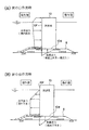
防波堤は、来襲する波浪で生じる波力に対して、その重量(自重)により安定性を確保している構造物である。この波力には、波が防波堤に押し寄せた状態(以後、波の山作用時)で作用する波力と、波が防波堤から引いた状態(以後、波の谷作用時)で作用する波力があり、それぞれの波力の算定には、合田式が一般的に用いられている。それぞれの状態における作用波力模式図を図1(A)、(B)に示す。防波堤10の重量は、この波力に対して、波の山作用時と波の谷作用時の両方において、滑動安全率SF((3)式参照)が1.2以上となるように定めている。
The breakwater is a structure that secures stability by wave weight (self-weight) against wave force generated by the incoming waves. This wave force includes a wave force acting when the wave is pushed against the breakwater (hereinafter, when the wave is acting on a mountain) and a wave force acting when a wave is pulled from the breakwater (hereinafter, when the wave is acting on a wave). In general, the Goda equation is used to calculate each wave force. FIG. 1A and FIG. 1B are schematic diagrams showing the acting wave force in each state. The weight of the
<滑動安定性の照査式>
SF=μ(W−U+FV)/FH≧1.2 …(3)
W:防波堤重量(気中重量)
U:浮力
FV:鉛直波力合力(鉛直下向きを正)
FH:水平波力合力
<Sliding stability verification formula>
SF = μ (W−U + F V ) / F H ≧ 1.2 (3)
W: Breakwater weight (air weight)
U: Buoyancy
F V : Vertical wave force resultant force (vertical downward is positive)
F H : Horizontal wave force resultant force
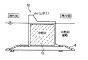
図2に示す如く、従来の防波堤(重力式)は殆どが箱形状であり、特許文献1や2に示される如く、その内部に砂や石(中詰砂と称する)12を投入することによって重み付けをしている。図において、14は上部工である。
As shown in FIG. 2, most of the conventional breakwaters (gravity type) are box-shaped, and as shown in
又、特許文献3乃至5に例示される如く、杭を打ち込むものもある。 In addition, as exemplified in Patent Documents 3 to 5, some piles are driven.
ところが、静水面下の部分には浮力が作用するため、重量の半分程度は相殺されてしまう。又、波作用時には、図1に示すように、底版10B全体に鉛直波力が作用する。この鉛直波力は、波の山が作用するときに鉛直上向きとなり(揚圧力と称する)、防波堤10を不安定にするように作用するため、(3)式を用いた照査により堤体重量を求めると、殆どの場合において、図1(A)に示した波の山作用時での必要重量となる。この時、図1(B)に示した波の谷作用時の滑動安全率は非常に大きくなり、図3に示す設計断面について行なった、次に示す滑動安全率の比較例の如く、波の谷作用時には大きな余剰耐力を有してしまうことになる。
However, since buoyancy acts on the portion below the still water surface, about half of the weight is offset. Further, at the time of wave action, as shown in FIG. 1, vertical wave force acts on the
滑動安全率の比較例
・波浪条件
有義波高H1/3=4.7m,設計波高HD=8.25m,周期T=11.0s
堤体幅B=6.7m,堤体重量(水中重量)W=2163.8(KN/m),摩擦係数μ=0.7
・作用波力(水平波力は岸向きがプラス,揚圧力は鉛直下向きがプラス)
<波の山作用時>
水平波力Fh=1156.7(KN/m),揚圧力Fu=−180.9(KN/m)
<波の谷作用時>
水平波力Fh=−489.4(KN/m),揚圧力Fu=139.7(KN/m)
・滑動安全率
<波の山作用時> 滑動安全率SFa=1.20
<波の谷作用時> 滑動安全率SFb=3.29
Comparative example of sliding safety factor ・ Wave conditions Significant wave height H 1/3 = 4.7m, Design wave height HD = 8.25m, Period T = 11.0s
Levee body width B = 6.7 m, dike body weight (in water weight) W = 2163.8 (KN / m), friction coefficient μ = 0.7
・ Working wave force (horizontal wave force is positive for the shore direction, and lifting pressure is positive for the vertical downward direction)
<During wave action>
Horizontal wave force Fh = 1156.7 (KN / m), lifting pressure Fu = −180.9 (KN / m)
<At the time of wave valley action>
Horizontal wave force Fh = -489.4 (KN / m), lifting pressure Fu = 139.7 (KN / m)
・ Sliding safety factor <During hill action> Sliding safety factor SFa = 1.20
<At the time of wave valley action> Sliding safety factor SFb = 3.29
このような問題点を解決するべく、特許文献1乃至4には、前壁部を港外側から港内側に向けて傾斜させることが記載され、特許文献5には凹面状とすることが記載されているが、十分とは言えない。
In order to solve such problems, Patent Documents 1 to 4 describe that the front wall portion is inclined from the outside of the port toward the inside of the port, and
特許文献3乃至5には、更に、杭を打ち込むことが記載されているが、施工が大変である。 Patent Documents 3 to 5 further describe driving a pile, but the construction is difficult.
本発明は、前記従来の問題点を解消するべくなされたもので、港湾や漁港の防波堤に用いるための、低コストの防波堤用構造体を提供することを第1の課題とする。 The present invention has been made to solve the above-mentioned conventional problems, and a first object is to provide a low-cost breakwater structure for use in a breakwater in a harbor or a fishing port.
本発明は又、前記防波堤用構造体を用いた防波堤を提供することを第2の課題とする。 It is a second object of the present invention to provide a breakwater using the breakwater structure.
本発明は、海底地盤上に載置可能な防波堤用構造体であって、該構造体は底板で海底地盤上に載置される骨組み構造からなり、重量部分が水面上部に置かれ、少なくとも平均水面が傾斜位置に来るように該骨組み構造体に配設された港内側に傾斜した不透壁を有する防波版を備え、前記底板を少なくとも港内側と港外側に分割し、該底板間に底板の無い部分を設けることにより、前記第1の課題を解決したものである。 The present invention is a structure for a breakwater that can be placed on the seabed ground , and the structure comprises a frame structure that is placed on the seabed ground by a bottom plate, and a weight portion is placed on the upper surface of the water , and at least an average comprising a breakwater plate having a FuTorukabe water surface is inclined to harbor inwardly disposed bone set structure to come to an inclined position, dividing the bottom plate at least inside and outside the harbor Harbor, the bottom plates the Rukoto provided portion having no bottom plate, is obtained by solving the first problem.
又、前記防波版の港内側に傾斜した不透壁と水面下で連接する鉛直の不透壁を設けたものである。 In addition, an impervious wall inclined on the inner side of the harbor of the wave preventing plate and a vertical impervious wall connected below the surface of the water are provided .
本発明は、又、前記の防波堤用構造体であって、次の(1)式で表わされた、港外側から港内側に押し寄せる波による該構造体に作用する押す力による該構造体の安全係数SFaと、次の(2)式で表わされた、港内側から港外側に引く波による該構造体に作用する引く力による該構造体の安全係数SFbとを、共に1.2以上としたものである。 The present invention is also the above-described structure for a breakwater, which is represented by the following formula (1), and is a structure of the structure by a pressing force acting on the structure by a wave urging from the outside of the harbor toward the inside of the harbor. Both the safety factor SFa and the safety factor SFb of the structure due to the pulling force acting on the structure due to the waves drawn from the inside of the port to the outside of the port represented by the following equation (2) are 1.2 or more. It is what.
SFa=(W−U+Fv1−Fv2)/FH …(1)
SFb=(W−U+Fv2)/FH …(2)
ここで、W:防波堤重量(気中重量)
U:浮力
Fv1:防波版斜面部に作用する鉛直波力
Fv2:底版に作用する鉛直波力(鉛直下向きを正)
FH:水平波力合力
SFa = (W−U + Fv1−Fv2) / F H (1)
SFb = (W−U + Fv2) / F H (2)
Where W: breakwater weight (air weight)
U: Buoyancy
Fv1: Vertical wave force acting on the wave-proof plate slope
Fv2: Vertical wave force acting on the bottom plate (vertical downward is positive)
F H : Horizontal wave force resultant force
本発明は、又、前記防波堤用構造体を、前記防波版が連続するように並べて海底地盤に配置することにより、前記第2の課題を解決したものである。 The present invention also solves the second problem by arranging the breakwater structures on the seabed ground side by side so that the breakwater plates are continuous.
本発明は、鋼管や形鋼で形成される骨組み構造体に防波版を取付ける構造形式とすることで、静水面下に作用していた浮力をできるだけ小さくした。防波版は、防波堤全体の安定性を向上させるために、港内側に向かって傾斜した斜面不透過壁とした。これにより、斜面壁に作用する波力は水平成分(水平波力)と鉛直成分(鉛直波力)に分割することができる。このとき、水平波力は従来の垂直壁に作用するよりも低減し、鉛直波力は鉛直下向き(防波堤を安定にする方向)に作用する。 In the present invention, the buoyancy acting under the hydrostatic surface is made as small as possible by adopting a structural form in which a wave-breaking plate is attached to a frame structure formed of a steel pipe or shape steel. In order to improve the stability of the breakwater as a whole, the breakwater plate is a slope impermeable wall inclined toward the inside of the harbor. Thereby, the wave force acting on the slope wall can be divided into a horizontal component (horizontal wave force) and a vertical component (vertical wave force). At this time, the horizontal wave force is smaller than that acting on the conventional vertical wall, and the vertical wave force acts vertically downward (in the direction of stabilizing the breakwater).
又、底版全体に作用していた鉛直波力(揚圧力)を低減するために、防波堤底面には、港外側と港内側にそれぞれ分割した底版を設置した。 In addition, in order to reduce the vertical wave force (lifting pressure) acting on the entire bottom plate, a bottom plate divided into the outer side of the port and the inner side of the port was installed on the bottom of the breakwater.
これらにより、波の山作用時において、水平波力は低減し、鉛直上向きに作用する鉛直波力(揚圧力)も低減するため、(3)式を満足する堤体重量Wは、従来よりも少なくすることができる。この時、波の谷作用時における滑動安全率SFbは、これまでの構造の場合よりも小さくなり、波の山作用時と谷作用時における滑動安全率SFa、SFbを同程度にすることができるため、無駄のない最適な防波堤断面とすることが可能となる。 As a result, the horizontal wave force is reduced and the vertical wave force (lifting pressure) acting vertically upward is reduced at the time of the wave action, so that the dam body weight W satisfying the equation (3) is larger than the conventional one. Can be reduced. At this time, the sliding safety factor SFb at the time of wave trough action is smaller than that of the conventional structure, and the sliding safety factors SFa and SFb at the time of wave crest action and trough action can be made comparable. Therefore, it is possible to obtain an optimum breakwater cross section without waste.
本発明によれば、鋼管や形鋼で形成される骨組み部材に、直立な不透過壁と港内側に向かって傾斜した斜面不透過壁からなる防波版、港外側と港内側にそれぞれ分離した底版、重量付けのための上部工を設置した構造形式とすることで、従来構造の防波堤よりも低コストで製作することができる。 According to the present invention, a frame member formed of a steel pipe or a shape steel is separated into a wave-breaking plate composed of an upright impervious wall and an inclined impervious wall inclined toward the inner side of the port, and separated into the outer side of the port and the inner side of the port. By adopting a structural form in which a bottom plate and a superstructure for weighting are installed, it can be manufactured at a lower cost than a conventional breakwater.
以下図面を参照して、本発明の実施形態を詳細に説明する。 Hereinafter, embodiments of the present invention will be described in detail with reference to the drawings.
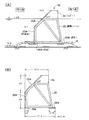
本実施形態の概略図を図4に示す。従来の重力式防波堤の中詰砂部を省略して、鋼管や形鋼で形成される鋼製フレームの骨組み部材(骨組み構造体)20を設け、その港外側に防波版22を取付ける。骨組み構造としているため、従来の箱形状の防波堤と比較して浮力は殆ど作用しない。防波版22は、防波堤10の安定性を向上させるために、上部22Aを斜面構造としている。防波堤10の上端には、作用する波力に対して必要となる重量付けのための上部工24を設ける。又、防波堤10の下端には、港外側と港内側のそれぞれに底版26A、26Bを設け、底面全体に作用していた揚圧力を低減させている。
A schematic diagram of this embodiment is shown in FIG. A conventional gravitational breakwater embedding sand portion is omitted, and a steel frame frame member (frame structure) 20 formed of a steel pipe or shape steel is provided, and a
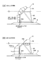
本発明による実施形態が、実際の構造形式として成立するか否かを検証するために水理実験を行った。水理実験では、設計に用いるための各部材に作用する波圧分布と防波堤全体の安定性を検証した。実験断面図を図5に示す。実験模型は、実物の重心・重量を基にフルード相似則を用いて縮小したものとし、縮尺率は1/50とした。波の山作用時(A)と波の谷作用時(B)に、各部材に作用する波圧分布を図6に示す。実験時の波浪条件は、現地換算値で、周期11.0s、波高8.25mである。これより、図6(A)に示した波の山作用時において、防波版22には合田式に斜面の効果を取り入れた細山田式、底版は港外側26Aのみに波圧が作用する。一方、図6(B)に示した波の谷作用時には、波高の1.0倍に相当する防波堤前面の水位低下量が静水圧分布として防波版22に作用し、底版は港外側26Aのみに作用する。また、上部工24の下面は、波高の0.2倍相当の静水圧分布を一様に作用させた。
A hydraulic experiment was conducted to verify whether the embodiment according to the present invention was established as an actual structural form. In the hydraulic experiment, the wave pressure distribution acting on each member used for the design and the stability of the whole breakwater were verified. An experimental cross-sectional view is shown in FIG. The experimental model was reduced using the fluid similarity law based on the center of gravity and weight of the real object, and the scale ratio was 1/50. FIG. 6 shows the wave pressure distribution acting on each member during the wave peak action (A) and the wave valley action (B). Wave conditions at the time of the experiment are local equivalent values, with a period of 11.0 s and a wave height of 8.25 m. 6A, at the time of the wave hill action shown in FIG. 6A, the wave-
今回の実験結果における波圧分布式の模式図を図7に示す。この波圧分布式を用いて、防波堤の安定性を検証するために滑動実験を行った。滑動実験は、図7で示される波圧分布式を用いて、図8に示す如く、滑動安全率SF=1.0となる防波堤を対象に、様々な波高を作用させて防波堤の滑動(変位)の有無により安定性を検証する手法である。滑動安全率SF=1.0以上において滑動(変位)がなければ、波圧分布式は妥当であり、本発明による実施形態の防波堤が成立可能となる。 FIG. 7 shows a schematic diagram of the wave pressure distribution formula in this experimental result. Using this wave pressure distribution equation, a sliding experiment was conducted to verify the stability of the breakwater. As shown in FIG. 8, using the wave pressure distribution formula shown in FIG. 7, the sliding experiment is performed on a breakwater having a sliding safety factor SF = 1.0 as shown in FIG. ) Is a method for verifying stability based on the presence or absence of If there is no sliding (displacement) at the sliding safety factor SF = 1.0 or more, the wave pressure distribution equation is appropriate, and the breakwater according to the embodiment of the present invention can be established.
実験結果を図9に示す。これより、滑動安全率SF=1.0以上での滑動(変位)は生じていないことから、図7に示す波圧分布式は妥当であり、本発明による防波堤が実際の構造形式として成立可能であることが実証できた。 The experimental results are shown in FIG. From this, the sliding (displacement) does not occur when the sliding safety factor SF = 1.0 or more. Therefore, the wave pressure distribution equation shown in FIG. 7 is valid, and the breakwater according to the present invention can be established as an actual structural form. It was proved that.
そこで、図5に示す断面を対象にして、図6に示す波圧分布式を用いて滑動安全率を求めた。その結果、波の山作用時と波の谷作用時の滑動安全率は従来構造と比べて同程度となっており、又、必要となる堤体重量Wは従来構造の7割程度であることから、本発明による防波堤は、従来構造と比較して低コストに製作することが可能である。 Therefore, for the cross section shown in FIG. 5, the sliding safety factor was obtained using the wave pressure distribution equation shown in FIG. As a result, the sliding safety factor at the time of wave crest action and at the time of wave trough action is comparable to that of the conventional structure, and the required dam weight W is about 70% of that of the conventional structure. Therefore, the breakwater according to the present invention can be manufactured at a lower cost than the conventional structure.
滑動安全率の比較
・波浪条件
有義波高H1/3=4.7m,設計波高HD=8.25m,周期T=11.0s
堤体幅B=12.8m,堤体重量(水中重量)W=1457.0(KN/m),摩擦係数μ=0.7
・作用波力(水平波力は岸向きがプラス,鉛直波力・揚圧力は鉛直下向きがプラス)
<波の峰作用時>
水平波力合力Fh=732.3(KN/m),鉛直波力合力Fv=292.6(KN/m),
揚圧力Fu=−54.0(KN/m)
<波の谷作用時>
水平波力合力Fh=−753.7(KN/m),鉛直波力合力Fv=−70.2(KN/m),
揚圧力Fu=40.5(KN/m),上部工下面の揚圧力Fv’=−135.0(KN/m)
・滑動安全率
<波の山作用時> 滑動安全率SFa=1.62
<波の谷作用時> 滑動安全率SFb=1.20
Comparison of sliding safety factor ・ Wave conditions Significant wave height H 1/3 = 4.7m, Design wave height HD = 8.25m, Period T = 11.0s
Levee body width B = 12.8m, dike body weight (in water weight) W = 14.57.0 (KN / m), friction coefficient μ = 0.7
・ Working wave force (Horizontal wave force is positive for shore, vertical wave force and lifting pressure is positive for vertical downward)
<During wave action>
Horizontal wave force resultant force Fh = 732.3 (KN / m), vertical wave force resultant force Fv = 292.6 (KN / m),
Lifting pressure Fu = -54.0 (KN / m)
<At the time of wave valley action>
Horizontal wave force resultant force Fh = −753.7 (KN / m), vertical wave force resultant force Fv = −70.2 (KN / m),
Lifting pressure Fu = 40.5 (KN / m), lifting pressure Fv ′ on the upper work lower surface = −135.0 (KN / m)
・ Sliding safety factor <During wave action> Sliding safety factor SFa = 1.62
<At the time of wave valley action> Sliding safety factor SFb = 1.20
本実施形態においては、重量付けのための上部工24と、港外側と港内側にそれぞれ分離した底板26A、26Bを併用していたので、効果が高い。なお、いずれか一方のみの構成を採用することも可能である。
In this embodiment, since the
8…基礎マウンド
10…防波堤
20…骨組み部材(骨組み構造体)
22…防波版
22A…斜面部
22B…直立部
24…上部工
26B…港内側底板
8 ...
22 ...
Claims (4)
次の(1)式で表わされた、港外側から港内側に押し寄せる波による該構造体に作用する押す力による該構造体の安全係数SFaと、
次の(2)式で表わされた、港内側から港外側に引く波による該構造体に作用する引く力による該構造体の安全係数SFbとが、共に1.2以上であることを特徴とする防波堤用構造体。
SFa=(W−U+Fv1+Fv2)/FH …(1)
SFb=(W−U+Fv2)/FH …(2)
ここで、W:防波堤重量(気中重量)
U:浮力
Fv1:防波版斜面部に作用する鉛直波力
Fv2:底版に作用する鉛直波力(鉛直下向きを正)
FH:水平波力合力 A structure for a breakwater according to claim 1 or 2 ,
The safety factor SFa of the structure represented by the following equation (1) due to the pushing force acting on the structure due to the waves urging from the outside of the harbor toward the inside of the harbor;
The safety factor SFb of the structure due to the pulling force acting on the structure due to the wave drawn from the inside of the port to the outside of the port represented by the following equation (2) is 1.2 or more. Breakwater structure.
SFa = (W−U + Fv1 + Fv2) / F H (1)
SFb = (W−U + Fv2) / F H (2)
Where W: breakwater weight (air weight)
U: buoyancy Fv1: vertical wave force Fv2 acting on the wave-blocking plate slope portion: vertical wave force acting on the bottom plate (vertical downward is positive)
F H : Horizontal wave force resultant force
Priority Applications (1)
| Application Number | Priority Date | Filing Date | Title |
|---|---|---|---|
| JP2004216030A JP4306552B2 (en) | 2004-07-23 | 2004-07-23 | Breakwater structure and breakwater |
Applications Claiming Priority (1)
| Application Number | Priority Date | Filing Date | Title |
|---|---|---|---|
| JP2004216030A JP4306552B2 (en) | 2004-07-23 | 2004-07-23 | Breakwater structure and breakwater |
Publications (2)
| Publication Number | Publication Date |
|---|---|
| JP2006037400A JP2006037400A (en) | 2006-02-09 |
| JP4306552B2 true JP4306552B2 (en) | 2009-08-05 |
Family
ID=35902679
Family Applications (1)
| Application Number | Title | Priority Date | Filing Date |
|---|---|---|---|
| JP2004216030A Expired - Lifetime JP4306552B2 (en) | 2004-07-23 | 2004-07-23 | Breakwater structure and breakwater |
Country Status (1)
| Country | Link |
|---|---|
| JP (1) | JP4306552B2 (en) |
-
2004
- 2004-07-23 JP JP2004216030A patent/JP4306552B2/en not_active Expired - Lifetime
Also Published As
| Publication number | Publication date |
|---|---|
| JP2006037400A (en) | 2006-02-09 |
Similar Documents
| Publication | Publication Date | Title |
|---|---|---|
| US7744310B2 (en) | Hydrostatically operated variable height bulkhead | |
| US9624636B2 (en) | Multi-stage suspended wave screen and coastal protection system | |
| JP4306552B2 (en) | Breakwater structure and breakwater | |
| CN201520954U (en) | Caisson platform for pier construction | |
| WO1994006970A1 (en) | Foundation arrangement for an offshore framework construction or subsea installation | |
| JPH09279540A (en) | Seismic strengthening structure for gravity port structure | |
| JP5405841B2 (en) | Tsunami resistance and storm surge reinforcement method for existing gravity structures | |
| JP5572540B2 (en) | Temporary deadline structure of the final deadline in the impermeable wall and its deadline method | |
| AU2017352093B2 (en) | Harbour plant and method for mooring a floating body in a harbour plant | |
| JP7440864B2 (en) | Embankment reinforcement method | |
| JP2014101663A (en) | Gravity-type breakwater | |
| JP2726611B2 (en) | How to set up an open caisson | |
| JP4237112B2 (en) | Caisson connection method and caisson structure | |
| JP5092047B1 (en) | Evacuation float | |
| JP3668332B2 (en) | Intake structure | |
| CN117627032A (en) | Set bridge deepwater foundation and construction method thereof | |
| JP6749571B2 (en) | Tsunami attenuation groove structure | |
| JP2009228268A (en) | Leg type offshore breakwater | |
| JP4701412B2 (en) | Artificial tidal flat and its construction method | |
| Douairi et al. | Upgrading techniques for quay walls | |
| JP4958064B2 (en) | Seismic reinforcement structure of quay | |
| JP2017206851A (en) | Coastal structure | |
| JP7396331B2 (en) | Improvement structure of existing quay wall and construction method of the improvement structure | |
| JP3440854B2 (en) | Reflected wave reduction structure with double-draft double curtain wall | |
| JP7561948B1 (en) | Tsunami defense triple wall floating system. |
Legal Events
| Date | Code | Title | Description |
|---|---|---|---|
| A621 | Written request for application examination |
Free format text: JAPANESE INTERMEDIATE CODE: A621 Effective date: 20060807 |
|
| A977 | Report on retrieval |
Free format text: JAPANESE INTERMEDIATE CODE: A971007 Effective date: 20080204 |
|
| A131 | Notification of reasons for refusal |
Free format text: JAPANESE INTERMEDIATE CODE: A131 Effective date: 20080219 |
|
| A521 | Request for written amendment filed |
Free format text: JAPANESE INTERMEDIATE CODE: A523 Effective date: 20080328 |
|
| TRDD | Decision of grant or rejection written | ||
| A01 | Written decision to grant a patent or to grant a registration (utility model) |
Free format text: JAPANESE INTERMEDIATE CODE: A01 Effective date: 20090414 |
|
| A01 | Written decision to grant a patent or to grant a registration (utility model) |
Free format text: JAPANESE INTERMEDIATE CODE: A01 |
|
| A61 | First payment of annual fees (during grant procedure) |
Free format text: JAPANESE INTERMEDIATE CODE: A61 Effective date: 20090427 |
|
| R150 | Certificate of patent or registration of utility model |
Ref document number: 4306552 Country of ref document: JP Free format text: JAPANESE INTERMEDIATE CODE: R150 Free format text: JAPANESE INTERMEDIATE CODE: R150 |
|
| FPAY | Renewal fee payment (event date is renewal date of database) |
Free format text: PAYMENT UNTIL: 20120515 Year of fee payment: 3 |
|
| FPAY | Renewal fee payment (event date is renewal date of database) |
Free format text: PAYMENT UNTIL: 20130515 Year of fee payment: 4 |
|
| FPAY | Renewal fee payment (event date is renewal date of database) |
Free format text: PAYMENT UNTIL: 20140515 Year of fee payment: 5 |
|
| S531 | Written request for registration of change of domicile |
Free format text: JAPANESE INTERMEDIATE CODE: R313531 |
|
| R370 | Written measure of declining of transfer procedure |
Free format text: JAPANESE INTERMEDIATE CODE: R370 |
|
| R370 | Written measure of declining of transfer procedure |
Free format text: JAPANESE INTERMEDIATE CODE: R370 |
|
| S531 | Written request for registration of change of domicile |
Free format text: JAPANESE INTERMEDIATE CODE: R313531 |
|
| R371 | Transfer withdrawn |
Free format text: JAPANESE INTERMEDIATE CODE: R371 |
|
| S531 | Written request for registration of change of domicile |
Free format text: JAPANESE INTERMEDIATE CODE: R313531 |
|
| R350 | Written notification of registration of transfer |
Free format text: JAPANESE INTERMEDIATE CODE: R350 |
|
| EXPY | Cancellation because of completion of term |