JP4303437B2 - Rod system in the bone marrow of the thigh - Google Patents
Rod system in the bone marrow of the thigh Download PDFInfo
- Publication number
- JP4303437B2 JP4303437B2 JP2001502758A JP2001502758A JP4303437B2 JP 4303437 B2 JP4303437 B2 JP 4303437B2 JP 2001502758 A JP2001502758 A JP 2001502758A JP 2001502758 A JP2001502758 A JP 2001502758A JP 4303437 B2 JP4303437 B2 JP 4303437B2
- Authority
- JP
- Japan
- Prior art keywords
- nail
- pin
- passage
- opening
- angle
- Prior art date
- Legal status (The legal status is an assumption and is not a legal conclusion. Google has not performed a legal analysis and makes no representation as to the accuracy of the status listed.)
- Expired - Fee Related
Links
- 210000000689 upper leg Anatomy 0.000 title description 88
- 210000001185 bone marrow Anatomy 0.000 title description 5
- 210000000988 bone and bone Anatomy 0.000 claims description 172
- 206010017076 Fracture Diseases 0.000 claims description 36
- 208000010392 Bone Fractures Diseases 0.000 claims description 32
- 238000011282 treatment Methods 0.000 claims description 18
- 230000008859 change Effects 0.000 claims description 7
- 230000007246 mechanism Effects 0.000 claims description 3
- 230000008878 coupling Effects 0.000 claims description 2
- 238000010168 coupling process Methods 0.000 claims description 2
- 238000005859 coupling reaction Methods 0.000 claims description 2
- 238000000034 method Methods 0.000 description 35
- 208000008924 Femoral Fractures Diseases 0.000 description 12
- 210000002320 radius Anatomy 0.000 description 10
- 238000002513 implantation Methods 0.000 description 9
- 238000003780 insertion Methods 0.000 description 8
- 230000037431 insertion Effects 0.000 description 8
- 210000002303 tibia Anatomy 0.000 description 6
- 230000008901 benefit Effects 0.000 description 5
- 210000000527 greater trochanter Anatomy 0.000 description 5
- 210000002758 humerus Anatomy 0.000 description 5
- 210000000623 ulna Anatomy 0.000 description 5
- 230000006835 compression Effects 0.000 description 4
- 238000007906 compression Methods 0.000 description 4
- 210000002436 femur neck Anatomy 0.000 description 4
- 239000000463 material Substances 0.000 description 3
- 208000002847 Surgical Wound Diseases 0.000 description 2
- 230000035876 healing Effects 0.000 description 2
- 210000004394 hip joint Anatomy 0.000 description 2
- 229910052751 metal Inorganic materials 0.000 description 2
- 239000002184 metal Substances 0.000 description 2
- 210000004872 soft tissue Anatomy 0.000 description 2
- VYZAMTAEIAYCRO-UHFFFAOYSA-N Chromium Chemical compound [Cr] VYZAMTAEIAYCRO-UHFFFAOYSA-N 0.000 description 1
- 241001391944 Commicarpus scandens Species 0.000 description 1
- 208000006670 Multiple fractures Diseases 0.000 description 1
- RTAQQCXQSZGOHL-UHFFFAOYSA-N Titanium Chemical compound [Ti] RTAQQCXQSZGOHL-UHFFFAOYSA-N 0.000 description 1
- 230000009471 action Effects 0.000 description 1
- 230000003466 anti-cipated effect Effects 0.000 description 1
- 229910052804 chromium Inorganic materials 0.000 description 1
- 239000011651 chromium Substances 0.000 description 1
- 229910017052 cobalt Inorganic materials 0.000 description 1
- 239000010941 cobalt Substances 0.000 description 1
- GUTLYIVDDKVIGB-UHFFFAOYSA-N cobalt atom Chemical compound [Co] GUTLYIVDDKVIGB-UHFFFAOYSA-N 0.000 description 1
- 238000005553 drilling Methods 0.000 description 1
- 230000000694 effects Effects 0.000 description 1
- 210000001981 hip bone Anatomy 0.000 description 1
- 239000007943 implant Substances 0.000 description 1
- 208000014674 injury Diseases 0.000 description 1
- 230000007794 irritation Effects 0.000 description 1
- 210000003127 knee Anatomy 0.000 description 1
- 210000000629 knee joint Anatomy 0.000 description 1
- 238000004519 manufacturing process Methods 0.000 description 1
- 235000013372 meat Nutrition 0.000 description 1
- 238000012986 modification Methods 0.000 description 1
- 230000004048 modification Effects 0.000 description 1
- 210000003205 muscle Anatomy 0.000 description 1
- 230000000399 orthopedic effect Effects 0.000 description 1
- 238000002360 preparation method Methods 0.000 description 1
- 230000001105 regulatory effect Effects 0.000 description 1
- 230000006641 stabilisation Effects 0.000 description 1
- 238000011105 stabilization Methods 0.000 description 1
- 229910001220 stainless steel Inorganic materials 0.000 description 1
- 239000010935 stainless steel Substances 0.000 description 1
- 239000010936 titanium Substances 0.000 description 1
- 229910052719 titanium Inorganic materials 0.000 description 1
- 230000008733 trauma Effects 0.000 description 1
Images


Classifications
-
- A—HUMAN NECESSITIES
- A61—MEDICAL OR VETERINARY SCIENCE; HYGIENE
- A61B—DIAGNOSIS; SURGERY; IDENTIFICATION
- A61B17/00—Surgical instruments, devices or methods, e.g. tourniquets
- A61B17/56—Surgical instruments or methods for treatment of bones or joints; Devices specially adapted therefor
- A61B17/58—Surgical instruments or methods for treatment of bones or joints; Devices specially adapted therefor for osteosynthesis, e.g. bone plates, screws, setting implements or the like
- A61B17/68—Internal fixation devices, including fasteners and spinal fixators, even if a part thereof projects from the skin
- A61B17/72—Intramedullary pins, nails or other devices
- A61B17/7216—Intramedullary pins, nails or other devices for bone lengthening or compression
-
- A—HUMAN NECESSITIES
- A61—MEDICAL OR VETERINARY SCIENCE; HYGIENE
- A61B—DIAGNOSIS; SURGERY; IDENTIFICATION
- A61B17/00—Surgical instruments, devices or methods, e.g. tourniquets
- A61B17/56—Surgical instruments or methods for treatment of bones or joints; Devices specially adapted therefor
- A61B17/58—Surgical instruments or methods for treatment of bones or joints; Devices specially adapted therefor for osteosynthesis, e.g. bone plates, screws, setting implements or the like
- A61B17/68—Internal fixation devices, including fasteners and spinal fixators, even if a part thereof projects from the skin
- A61B17/72—Intramedullary pins, nails or other devices
- A61B17/7233—Intramedullary pins, nails or other devices with special means of locking the nail to the bone
- A61B17/7241—Intramedullary pins, nails or other devices with special means of locking the nail to the bone the nail having separate elements through which screws pass
-
- A—HUMAN NECESSITIES
- A61—MEDICAL OR VETERINARY SCIENCE; HYGIENE
- A61B—DIAGNOSIS; SURGERY; IDENTIFICATION
- A61B17/00—Surgical instruments, devices or methods, e.g. tourniquets
- A61B17/56—Surgical instruments or methods for treatment of bones or joints; Devices specially adapted therefor
- A61B17/58—Surgical instruments or methods for treatment of bones or joints; Devices specially adapted therefor for osteosynthesis, e.g. bone plates, screws, setting implements or the like
- A61B17/68—Internal fixation devices, including fasteners and spinal fixators, even if a part thereof projects from the skin
- A61B17/72—Intramedullary pins, nails or other devices
- A61B17/7233—Intramedullary pins, nails or other devices with special means of locking the nail to the bone
- A61B17/725—Intramedullary pins, nails or other devices with special means of locking the nail to the bone with locking pins or screws of special form
-
- A—HUMAN NECESSITIES
- A61—MEDICAL OR VETERINARY SCIENCE; HYGIENE
- A61B—DIAGNOSIS; SURGERY; IDENTIFICATION
- A61B17/00—Surgical instruments, devices or methods, e.g. tourniquets
- A61B17/56—Surgical instruments or methods for treatment of bones or joints; Devices specially adapted therefor
- A61B17/58—Surgical instruments or methods for treatment of bones or joints; Devices specially adapted therefor for osteosynthesis, e.g. bone plates, screws, setting implements or the like
- A61B17/68—Internal fixation devices, including fasteners and spinal fixators, even if a part thereof projects from the skin
- A61B17/74—Devices for the head or neck or trochanter of the femur
- A61B17/742—Devices for the head or neck or trochanter of the femur having one or more longitudinal elements oriented along or parallel to the axis of the neck
- A61B17/744—Devices for the head or neck or trochanter of the femur having one or more longitudinal elements oriented along or parallel to the axis of the neck the longitudinal elements coupled to an intramedullary nail
-
- A—HUMAN NECESSITIES
- A61—MEDICAL OR VETERINARY SCIENCE; HYGIENE
- A61B—DIAGNOSIS; SURGERY; IDENTIFICATION
- A61B17/00—Surgical instruments, devices or methods, e.g. tourniquets
- A61B17/56—Surgical instruments or methods for treatment of bones or joints; Devices specially adapted therefor
- A61B17/58—Surgical instruments or methods for treatment of bones or joints; Devices specially adapted therefor for osteosynthesis, e.g. bone plates, screws, setting implements or the like
- A61B17/68—Internal fixation devices, including fasteners and spinal fixators, even if a part thereof projects from the skin
- A61B17/74—Devices for the head or neck or trochanter of the femur
- A61B17/742—Devices for the head or neck or trochanter of the femur having one or more longitudinal elements oriented along or parallel to the axis of the neck
- A61B17/748—Devices for the head or neck or trochanter of the femur having one or more longitudinal elements oriented along or parallel to the axis of the neck with means for adapting the angle between the longitudinal elements and the shaft axis of the femur
-
- A—HUMAN NECESSITIES
- A61—MEDICAL OR VETERINARY SCIENCE; HYGIENE
- A61B—DIAGNOSIS; SURGERY; IDENTIFICATION
- A61B17/00—Surgical instruments, devices or methods, e.g. tourniquets
- A61B17/56—Surgical instruments or methods for treatment of bones or joints; Devices specially adapted therefor
- A61B17/58—Surgical instruments or methods for treatment of bones or joints; Devices specially adapted therefor for osteosynthesis, e.g. bone plates, screws, setting implements or the like
- A61B17/68—Internal fixation devices, including fasteners and spinal fixators, even if a part thereof projects from the skin
- A61B17/72—Intramedullary pins, nails or other devices
- A61B17/7216—Intramedullary pins, nails or other devices for bone lengthening or compression
- A61B17/7225—Intramedullary pins, nails or other devices for bone lengthening or compression for bone compression
-
- A—HUMAN NECESSITIES
- A61—MEDICAL OR VETERINARY SCIENCE; HYGIENE
- A61B—DIAGNOSIS; SURGERY; IDENTIFICATION
- A61B17/00—Surgical instruments, devices or methods, e.g. tourniquets
- A61B17/56—Surgical instruments or methods for treatment of bones or joints; Devices specially adapted therefor
- A61B17/58—Surgical instruments or methods for treatment of bones or joints; Devices specially adapted therefor for osteosynthesis, e.g. bone plates, screws, setting implements or the like
- A61B17/68—Internal fixation devices, including fasteners and spinal fixators, even if a part thereof projects from the skin
- A61B17/84—Fasteners therefor or fasteners being internal fixation devices
- A61B17/86—Pins or screws or threaded wires; nuts therefor
- A61B17/8685—Pins or screws or threaded wires; nuts therefor comprising multiple separate parts
Landscapes
- Health & Medical Sciences (AREA)
- Orthopedic Medicine & Surgery (AREA)
- Surgery (AREA)
- Life Sciences & Earth Sciences (AREA)
- Heart & Thoracic Surgery (AREA)
- Nuclear Medicine, Radiotherapy & Molecular Imaging (AREA)
- Engineering & Computer Science (AREA)
- Biomedical Technology (AREA)
- Neurology (AREA)
- Medical Informatics (AREA)
- Molecular Biology (AREA)
- Animal Behavior & Ethology (AREA)
- General Health & Medical Sciences (AREA)
- Public Health (AREA)
- Veterinary Medicine (AREA)
- Surgical Instruments (AREA)
Description
【発明の属する技術分野】
【0001】
本発明は、骨折治療技術に関し、特に、本発明は、一様な骨髄内ロッドを用いて、種々の典型的な大腿骨骨折を治療するためのシステムに関するものである。
【従来の技術】
【0002】
大腿骨は一般に股関節部から膝に伸びる幹を有する。大腿骨幹の基端部は大腿骨頭部につながる大腿骨頸部を含む。頭部は寛骨のくぼみに嵌合して股関節部に球関節を形成する。大腿骨幹の末端部は脛骨の上端部に係合し膝関節を形成する。総体的に、大腿骨は人体において最も長く最も強い骨の一つである。しかし、大腿骨の各部分は非常に骨折しやすい。
【0003】
大腿骨折の内部固定は最も一般的な整形外科手術の一つである。実際は、大腿骨頸部、中間部、末端部の骨折を含む、多くのタイプの大腿骨折がある。大腿骨が折れた場合、折れた骨を治療期間中ほぼ不動状態に一体的に接合しなければならない。折れた骨の一方が他方に対して長さ方向、横断方向あるいは回転方向に動くと、治療期間が大幅に延びたり、不適切な治癒が生じる可能性がある。骨折部位の周りの領域を固定するために、一般に二つの異なる内部固定法が使用されている。
【0004】
一つの方法は、接合する2つの骨部分に金属ピンを打ち込み、接合すべき骨の外面に圧接する一つまたは複数の板にそれら金属ピンを接続する。しかし、この方法はその骨を取り囲む肉や筋肉を傷つけ、骨に打ち込まれた多数のピンが骨の硬い外層を弱くする傾向がある。板も骨にストレスを与えがちであり、多くの大腿骨折に対して常に十分に応力を支えることができるわけではない。
【0005】
さらに、板で補強された骨は、板がない元の骨と同じ強度を常に持つわけではない。大腿骨折を治療する二つ目の方法は、骨髄内釘を大腿骨の骨髄管内に挿入し、各種方法によってそれを内部に固定する。骨折部位での骨が完全に治癒した後に、その釘は大腿骨の基端部にあけた穴を介して取り除くことができる。大腿骨折の内部固定のために、骨髄内安定および固定方法を利用した各種の装置が開発されている。大腿骨折の骨髄内固定の分野において多くの技術的進歩がなされてきたが、いくつかの問題領域が依然として残っている。
【0006】
それらの問題の一つは、現在使用可能なほとんどの骨髄内固定システムはそれぞれが特定のタイプの大腿骨折にしか適用されないため、非常に特殊な各種形状のシステムを多数用意しなくてはならないことである。これによって、病院や外傷センターは様々な患者を受け入れるために、様々な形状を有する長さが少しずつ異なる釘や補助部品の在庫を大量に持たなくてはならなくなる。予想されるすべての事故に備えてそのような大量在庫を維持することは、複雑であるだけでなく、非常に費用がかかる。したがって、外科医が固定装置を選択して埋め込む際に間違える可能性が高くなる。同様に、各種の骨髄内固定法に関わる在庫コストも大幅に増えるため、小さな医療施設の場合、より安価で潜在的に効果の低い大腿骨折治療法に切替えざるを得なくなることが考えられる。
【0007】
もう一つの問題は、特に大腿骨頸部または頭部を治療するために使われる骨髄内ロッドシステムである。これらの装置は普通、横断固定部材(釘、ピン、ねじ等)を含む。この横断固定部材は大腿骨頸部の縦軸に沿って配置され、その先端部を大腿骨頭部に埋め込むことによって大腿骨頭部を把持し骨折部位を固定するものである。固定部材は骨髄内ロッドに対して動作可能に接続され、固定部材とロッドとが互いに固定関係を維持している。残念ながら、この接続構造は、回復しつつある患者の通常の活動から生じる力が加わったときに、固定部材が骨髄内ロッドに対して回転または平行移動するのを常に防止するわけではない。さらに、これらの装置に使用される骨髄内ロッドは普通、単一の固定用途に特化しており他の用途に使用できない。したがって、高いレベルの在庫を維持するコストは大幅に増える。さらに、ロッドに対する固定部材の角度を変えたい場合、普通そのような角度変更を可能にするために固定部材またはロッド部材のいずれかに大幅な変更を加えなければならず、これが在庫レベルしたがって在庫コストを引き上げることになる。
【0008】
さらに別の問題領域において、大腿骨に対してロッドを固定するために横断ロック骨ねじを使用する必要が生じることがある。ロックナットをロックねじの末端部にねじ込んでロックねじのゆるみを防止することができる。残念ながら、ロックナットをロックねじの端部に取り付けるには、さらに外科的な切開が必要であり柔らかい組織を刺激してしまう。
【0009】
さらに別の問題領域において、骨髄内ロッドを骨髄管に挿入して2つ以上の骨ねじで大腿骨に固定する際、外科医がいくら努力しても、ロッドを挿入したために骨折部位が過度に圧縮されたり離れ過ぎたりすることがある。従来の骨髄内ロッドでは、残念ながら、最初に1つ以上の骨ねじを外して手で骨折部位を引き離したり圧縮することなしに近接状態を調整することは実質的に不可能である。したがって大腿骨に沿った別の位置に骨ねじを再度挿入することによって骨髄内ロッドを大腿骨に再び固定しなければならない。
【0010】
したがって、これらの問題を解決する骨折治療法が求められている。本発明はこの要求を満たすものであり、新規かつ自明ではない方法で他の利益および利点を提供する。
【発明が解決しようとする課題】
【0011】
本発明は骨折治療の技術に関する。本発明は多くの面で斬新で、自明ではなく、様々な利点を提供する。本明細書で述べる発明の実際の内容は添付の請求項によってのみ定められるが、選択した形態の好ましい実施例とその特徴を以下に簡単に述べる。
【0012】
本発明の一形態は骨折を釘と横断部材を使って治療するもので、その釘は開口を有し、横断部材は骨係合部と接続部とを含む。接続部は貫通孔を有し、釘はその貫通孔を通過する寸法を有する。ピンが調整可能に横断部材に接続されて、横断部材を釘にしっかりと組み込む。
【0013】
本発明の更なる形態において、骨折を治療する方法は骨髄管を横切って大腿骨内に第1の穴を形成し、横断部材をその第1穴に挿入する。横断部材は大腿骨の骨髄管に関連して位置付けられる貫通孔を含み、貫通孔が骨髄管に一致することが好ましい。この方法はさらに骨髄管に交わる第2の穴を形成し、その第2の穴を介して骨髄内釘を骨髄管内に挿入する。釘は横断部材の貫通孔を通過する。釘は横断部材に一致する開口を有する。横断部材に接続されたピンを釘の開口に挿入することによって釘を横断部材に堅固に組み合わせることができる。
【0014】
本発明のさらに別の形態において、骨折治療のためのシステムは、第1端部とそれに対して縦軸に沿って反対側の第2端部を有する釘を含む。第1端部は釘を貫通する開口を規定し、その開口は釘の縦軸に対して斜角を成す角度付面を有する。さらにシステムは、1対の開口を対抗する側面に有するスリーブを含む。スリーブを釘の端部に外挿したとき釘の第1端部の開口とスリーブの開口が一致して通路を形成する。骨係合部材が通路に挿入されて角度付面に当接する。
【0015】
本発明のさらに別の形態において、骨折治療装置は縦軸とそれにほぼ垂直な横断軸を有する細長い釘を含む。釘は横断軸に沿って延びる横断開口を有し、その開口は上面と反対側の下面とによって画定される。上面又は下面の少なくとも1つによって縦軸方向に延びる突起を規定し、それによって釘内の開口の寸法を狭める。釘の開口および突起は、大体骨折等の特定のタイプの骨折の治療に適した1つ以上の他の部材と協働するように構成することができる。
【0016】
本発明の他の形態によれば、骨折治療システムは釘を含み、その釘は縦軸、横断軸、および横断軸に沿って延びかつ荷重支持面によって画定される開口を有する。骨折治療システムはさらに、対向側面に1対の開口を配置したスリーブを含む。スリーブが釘に外挿されたとき釘の開口およびスリーブの開口が一致して通路を形成する。骨係合部材はその通路を通過するような寸法を有する。さらに、システムは、スリーブに対して縦軸方向に力を与えて、骨係合部材を荷重支持面に締め付ける手段を含んでもよい。
【0017】
本発明のさらに別の形態は、釘を有する骨折治療技術を含む。その釘は縦軸、釘を貫通する細長い開口、およびその開口に交差する縦軸通路を有する。骨係合部材がその開口を通過する。骨係合部材が釘開口を貫通しているときに、位置決め装置を調整して、釘に対して縦軸に沿って骨係合部材の位置を変えることができる。この装置は骨折部位の圧縮あるいは引き離しを容易にするために利用できる。
【0018】
したがって、本発明の1つの目的は改善された骨折治療システムを提供することである。このシステムは大腿骨折の治療に用いることが好ましい。
【0019】
さらにあるいはその代わりとして、別の目的は骨折治療、特に大腿骨等の長い骨の改善された骨折治療方法を提供することである。
【0020】
さらにあるいはその代わりとして、さらに別の目的は骨折治療に伴う複雑さと在庫コストを低減することである。
【0021】
本発明の他の目的、特徴、形態、実施例、観点、利点および利益は以下の説明および添付図面から当業者には明らかとなるであろう。
【発明の実施の形態】
【0022】
本発明の原理の理解を助けるために、図面に示した実施例を参照して説明する。また以下の説明が本発明の範囲を制限するものではないことを理解されたい。すなわち、本発明の技術分野に精通した当業者が通常発想するように、図示された実施例に変更や改造を加えたり、図示した本発明の原理をさらに適用することが考えられる。
【0023】
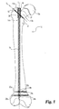
図1と図2は本発明の一実施例による骨髄内システム10を示す。システム10は大腿骨12に埋め込まれた状態が示されており、細長い骨髄内ロッドまたは釘14、スリーブ16および骨係合部材18を含む。システム10はまた留め具20および係止骨ねじ22a、22bを含む。図1は第1の係止形態に使用されるシステム10を示しており、骨係合部材18が大腿骨12内に順方向に配置されている。図2はシステム10の第2の係止形態を示し、骨係合部材18が大腿骨12内に逆方向に配置されている。大腿骨12の大転子12aの尖頭部、頸部12b、および頭部12cが図1と図2に示されている。図ではシステム10は人間の大腿骨12に埋め込まれているが、脛骨、上腕骨、橈骨、尺骨および腓骨等を含む当業者が考えつく他の骨にも使用することができる。
【0024】
釘14は基端部14aおよび末端部14bを含む。釘14ははまた基端部14aと末端部14bの間を釘14の長さに渡って延びる中心縦軸L1を有する。大人の人間の大腿骨に適用する場合、基端部14aは約11−13ミリの直径を有することが好ましい。釘14の残りの部分の直径は、固定手順の要求および外科医の好みによって変わる。釘14は全体的に円形の断面を有するが、当業者が思いつく他の適当な形状も採用することができる。
【0025】
図3−5をさらに参照すると、釘14の部分14bは全体的に平行な横断貫通孔24a、24bを有し、それぞれが係止骨ねじ22a、22bを受け入れるような寸法に形成されている。末端部14bはまた横断貫通孔24cを有し、これは横断貫通孔24a、24bにほぼ垂直に延び、係止骨ねじ22c(図示せず)を受け入れるような寸法に形成されている。基端部14aは開口26とねじが切られた横断貫通孔28を有し、これらは両方とも軸L1をほぼ横切るように第1側面14cから第2側面14dへ釘14を貫通して延びている。第1側面14cはほぼ第2側面14dに対向している。基端部14aはまた軸L1にほぼ沿って延びるねじが切られた縦軸穴29を有する。この縦軸穴29は、釘14を大腿骨12内に、および外に、案内するための釘挿入/取り出し器具を受け入れるものである。釘14はまた、穴29に交差して軸L1にほぼ沿って延びる縦軸通路30を有し、これによって釘14を大腿骨12内に挿入するのを助ける案内ワイヤ(図示せず)をオプションとして使用できるようにしている。
【0026】
特に図3と図5を参照すると、開口26は互いに対向する上面32と下面31によって区画されている。下面31は横断軸T1にほぼ平行な第1角度付面31aを含む。上面32は横断軸T1に沿って第1角度付面31aからオフセットした第二角度付面32aを含む。角度付面31a、32aは横断軸T1にほぼ平行である。横断軸T1は釘14の中心縦軸L1に対して斜角α1を有する。角度α1は120−150度の範囲が好ましく、約135度がより好ましい。第1角度付面31aと第2角度付面32aは協同して中心縦軸L1に対してほぼ角度α1を有する通路33を定める。第1通路33は骨係合部材18を受け入れるような寸法に形成されている。
【0027】
下面31はまた、横断軸T2にほぼ平行な第3角度付面31bを含む。上面32はまた、横断軸T2に沿って第3角度付面31bからオフセットした第4角度付面32bを含む。この第4角度付面32bも横断軸T2にほぼ平行である。図2と比較すると、横断軸T2もまた釘14の中心縦軸L1に対して斜角α2を有する。角度α2は120−150度の範囲が好ましく、約135度がより好ましい。第3角度付面31bと第4角度付面32bは協同して中心縦軸L1に対してほぼ角度α2を有する通路34を定める。第2通路34は骨係合部材18を受け入れるような寸法に形成されている。
【0028】
第1角度付面31aと第3角度付面31bは協同して第1突起35を画定する。この第1突起35は縦軸方向に延びて、中心縦軸L1に沿う釘14内の開口26寸法を狭める。同様に、第2角度付面32aと第4角度付面32bは協同して第2突起36を画定する。この第2突起36は第1突起35とはほぼ反対の縦軸方向に延びて、中心縦軸L1に沿う釘14内の開口26寸法を狭める。好ましい実施例において、各突起35,36は頂点を構成し、それによって釘14の両側面14c、14dのほぼ中間位置において中細通路36aを画定する。しかし、第1突起35と第2突起36は当業者が思いつくようないかなる他の幾何学形状を採用することもできる。例えば、第1突起35と第2突起36は丸くすることもできる。同様に、他の例として突起35、36の内一つ又は両方を取り除いても良い。角度付面31a、31b、32a、32bは骨係合部材18に合わせて概ね凹面を成しているが、当業者が思いつくような他の形状も考えられる。例えば、角度付面31a、31b、32a、32bを平坦にしたり、骨係合部材18の外面に合わせて他の形状を採用することができる。
【0029】
図4にはシステム10のスリーブ16が示してある。スリーブ16は概ね円筒形状をしており、基端部16a、末端部16bおよび側壁37を画定する。スリーブ16は図3に示す釘14の基端部に外挿される寸法に形成されている。したがって末端部16bは基端部14aが挿入されるように開放されている。スリーブ16はまた末端部16bで終端する内方に傾斜したテーパエッジ38を画定し、これによってスリーブ16が骨内を滑動しやすくしている。基端部16aはねじ付穴29に接近できるように開口39を有しており、これによって釘挿入/取り出し器具(図示せず)を通すことができる。側壁37はスリーブ16の両対向側面にオフセット開口40a、40bを有する。オフセット開口40a、40bは概ね円形で、骨係合部材18を受け入れるように整合され寸法が決められている。側壁37はさらにスリーブ16の両対向面に、対向横断開口42a、42bを有する。横断開口42a、42bはほぼ円形で留め具20を受け入れるように整合され寸法が決められている。
【0030】
図5には骨係合部材18が示される。骨係合部材18は基端部18aと末端部18bを含む。骨係合部材18は概ね円形の断面を有し、大人の大腿骨折治療のために5.5-6.5ミリメートルの直径を有することが好ましい。末端部18bは骨44に固定的に係合しそれを把持するための手段を含む。骨係合部材18は図5に示すようなねじを切った末端部18bを有する骨ねじであってもよいし、あるいはらせん状に捻った板(図示せず)から形成した末端部18bを有する骨ブレードであってもよい。あるいは末端部18bは当業者が思いつくような、骨係合のための他の形状としてもよい。
【0031】
図5に示すように、スリーブ16が釘14の基端部14aに外挿されるとき、スリーブ16のオフセット開口40a、40bが横断軸T1に沿って釘14の開口26および通路33に整合するように位置合わせされる。オフセット開口40a、40bおよび開口26は合わせて通路33と一致する通路50を画定する。通路50は一側面で第1角度付面31aによって、また他の側面において第2角度付面32aによって規制される。骨係合部材18が滑りながら通路50に挿入され横断軸T1に沿って案内されるとき、骨係合部材18は第1および第2角度付面31a、32aのいずれか又は両方と当接する。この当接関係は本質的に荷重支持とすることができる。骨係合部材18は、中心縦軸L1周りのその回転位置および中心縦軸L1に沿った並進位置が、通路50を貫通したときにほぼ固定されるように通路50に対して寸法が決められている。
【0032】
図5に示すように、スリーブ16が釘14の基端部14aに外挿されるとき、スリーブ16の横断開口42a、42bが釘14の貫通孔28に整合される。留め具20が開口42aを通って貫通孔28にねじ込まれ、スリーブ16を開放可能に釘14に固定する。もう一つの留め具20が開口42bを通って貫通孔28にねじ込まれ、さらにスリーブ16を釘14に固定する。2つの留め具20はスリーブ16を開放可能に釘14に固定するように示したが、単一の留め具を使ってスリーブ16を釘14にしっかりと固定することもできる。釘14を大腿骨12内に挿入するのを助けるためにガイドワイヤ(図示せず)をオプションとして使用する際にガイドワイヤとの干渉を避けるために、留め具20は縦軸通路30を遮ることなくスリーブ16を釘14に固定するのに十分に深く貫通孔28に進入する長さを有する。さらに別の実施例において、留め具20、貫通孔28および横断開口42a、42bの一つ以上を全く使用しないことも可能である。
【0033】
スリーブ16を釘14に対して180度回転することによって、骨係合部材18の順方向から逆方向へ、あるいはその逆に、構成を変えることができる。同様に、いずれの係止形状を使用しても、単にスリーブ16を釘14に対して180度回転させるだけでシステム10の同じコンポーネントを使って、左又は右の大腿骨を治療することができる。したがって、スリーブ16のオフセット開口40a、40bは横断軸T2に沿って釘14の開口26を介して通路34と一致するように位置決めし直す。オフセット開口40a、40bおよび開口26は合わせて、通路34と一致する通路52を画定する。通路52は一側面で第3角度付面31bによって、また他の側面において第4角度付面32bによって規制される(図2および図5を参照)。骨係合部材18が滑りながら通路52に挿入され横断軸T2に沿って案内されるとき、骨係合部材18は第3および第4角度付面31b、32bのいずれか又は両方と当接する。この当接関係は荷重支持に適したものであるのが好ましい。また中心縦軸L1周りの回転および中心縦軸L1に沿った並進に関して骨係合部材18をほぼ固定する。
【0034】
システム10の他の実施例において、中心縦軸L1に対する骨係合部材18の角度整合は、スリーブ16の形状を変えることによって変更することができる。具体的には、オフセット開口40a、40bはα1以外の角度で整合させることができる。これらの実施例において、第1通路50 は釘14の横断軸T1に沿って傾斜してはいない。したがって、骨係合部材18が滑りながら第1通路50内に挿入されるとき、骨係合部材18は第1突起35または第2突起36のいずれかに接触するが、第1角度付面31a又は第2角度付面32aに当接することはない。しかし、この構成でも、釘14に対して軸方向および回転方向に骨係合部材18を固定するのに適している。
【0035】
次に、図1および図2を参照して、システム10における大腿骨埋め込み手順を説明する。埋め込み手順は一般に、大転子12aの尖頭に対してわずかに内側の位置から骨髄管内にかつそれにほぼ平行に縦軸穴を形成する。この縦軸穴はドリルで形成することが好ましい。スリーブ16は釘14の基端部14aに外挿され、留め具20を横断貫通孔28にねじ込むことにより釘14に固定される。上述のように、システム10は釘14に対するスリーブ16の回転方向の位置によって第一又は第二の係止形態において使用することができる。
【0036】
図1は大腿骨12の順方向形態に対応する第1の係止形態のシステム10を示す。この第1の係止形態において、オフセット開口40a、40bが釘14の開口26に合うようにスリーブ16を位置付けて釘14に固定することにより、通路52が横断軸T2に沿って画定される。スリーブ16をそれに固定された釘14は縦軸穴を介して骨髄管内に挿入される。横断軸T2に対応する位置で骨髄管を横切るように横断孔を大腿骨12に貫通形成する。横断孔は骨髄管と交差し、骨係合部材18を受け入れるような寸法を有する。この横断孔もまたドリルによって形成されるのが好ましい。骨係合部材18は横断孔内に挿入され釘14とスリーブ16に形成された通路52を通る。その結果、骨係合部材18は中心縦軸L1に沿った並進又は中心縦軸L1周りの回転を防ぐように固定されるのが好ましい。通路52内に挿入されたとき、骨係合部材18は概ね大転子12aに対してわずかに外側の大腿骨入口点から頸部12bの基部の下方の終端点まで延びる。釘14の横断貫通孔24a、24bに一致するように、ほぼ平行な穴が骨髄管を横切って中心縦軸L1にほぼ垂直に大腿骨12を貫通して形成される。これらの穴もドリルによって明けられるのが好ましい。係止骨ねじ22a、22bを大腿骨12に挿入して釘14の横断貫通孔24a、24bに通すことによって、釘14はさらに所定位置に固定される。
【0037】
図2と図5は大腿骨12の逆方向形態に対応する第2の係止形態のシステム10を示す。この第2の係止形態において、オフセット開口40a、40bが釘14の開口26に合うようにスリーブ16を位置付けて釘14に固定することにより、通路50が横断軸T1に沿って画定される。骨髄管への挿入は図1に関連して説明したのとほぼ同じ方法で行う。スリーブ16をそれに固定された釘14は大転子12aの内側の縦軸穴を介して骨髄管内に挿入される。横断軸T1に対応する位置で骨髄管を横切るように横断孔を大腿骨12に形成する。横断孔は骨係合部材18を受け入れるような寸法を有する。骨係合部材18は横断孔に挿入されて通路50を貫通する。このように構成された骨係合部材18は概ね頸部12bを通って頭部12c内に伸びる。ほぼ平行な穴が骨髄管を横切って中心縦軸L1にほぼ垂直に大腿骨12を貫通して形成される。これらの穴は釘14の横断貫通孔24a、24bにほぼ一致する。係止骨ねじ22a、22bを大腿骨12に挿入して釘14の横断貫通孔24a、24bに通すことによって、釘14はさらに所定位置に固定される。
【0038】
次に釘14を製作する好ましい方法を説明する。この好ましい方法において横断軸T1に対応する方向(角度α1)に第1の穴を基端部14aに貫通させる。釘14の中心線にほぼ対応する点において、横断軸T2(角度α2)に対応し第1の穴に交差する方向に、第2の穴を基端部14aに貫通させる。第1と第2の穴は骨係合部材18がそれらを貫通するように寸法が定められる。これによって第1の穴は第1角度付面31aと第2角度付面32aを画定し、第2の穴は第3角度付面31bと第4角度付面32bを画定する。下面31と上面32の間の残りの材料を取り除いて釘14を貫通する開口26を形成し、図示のような突起35、36が得られる。
【0039】
図6は本発明の別の実施例による骨髄内システム100を示す。システム10に関して先に説明したものと同じ参照番号についてはそれらと同じ特徴を表す。システム100は大腿骨12内に埋め込まれた状態が示してあり、骨髄内ロッド又は釘14、横断部材102、ピン103、係止ねじ104および止めねじ105を含む。システム100はまた係止骨ねじ22a、22bを含む。システム100は人間の大腿骨12に埋め込まれた状態を示しているが、システム100は当業者が思いつくような他の骨、例えば脛骨、上腕骨、橈骨、尺骨、腓骨等にも使用できる。システム100は図2において先に説明した第2の係止形態のシステム10と同じような治療に使用できるが、大腿骨12の基部の骨折に使用するのが好ましく、さらには頸部12bと頭部12cの間の骨折に使用することがより好ましい。システム100の同じコンポーネントを使って、横断部材102を釘14に対して180度回転することによって左あるいは右の大腿骨を治療することができる。
【0040】
図7−図12はシステム100の構造と組み立てに関して更なる詳細を提供する。図7において、横断部材102とピン103の構造上の詳細を示す。横断部材102は縦軸中心線L2を規定し、円筒接続部106と骨係合部108を含む。接続部106は全体的に円筒形状をしており、側壁110を有する。側壁110はほぼ軸L2に沿って延びる通路112を規定する。接続部106はまた基端部106aと末端部106bを含む。基端部106aは通路112部分に沿って延びる内ねじ部114を含む。末端部106bは、横断部材102が大腿骨12内に挿入されたときに骨の内部での移動を容易にするために、外部内向きテーパ116を有する。末端部106bはまた骨係合部108を接続部106と摺動可能な接触状態に保つための内部保持リップ118を有する。その動作は後で明らかとなる。
【0041】
貫通孔120が接続部106に形成されている。貫通孔120はほぼ円筒形状で釘14の基端部14aの外径よりもわずかに大きい直径を有する。あるいは、貫通孔120は楕円形あるいは釘14の基端部14aに対応するいかなる形状であってもよい。さらに、貫通孔120と釘14の基端部14aは、基端部14aが貫通孔120内に挿入されたときに横断部材102が釘14に対して回転移動するのを防ぐために、非対称あるいはそのような形状を有することができる。同様に、貫通孔120と釘14の基端部14aが同じ方向にまたほぼ同じ角度でテーパ−をつけられていれば、横断部材102と釘14がしっかりと係合し合って回転移動を防止するのに役立つ。
【0042】
釘14が接続部を貫通したときに接続部が軸L1に対して選択された角度関係を保つように貫通孔120が接続部102に形成されている。この関係は軸L1とL2の間の角度α3に対応し、約130−145度の範囲であることが好ましい。さらにシステム100にとっては角度α3は図6に示した角度α2に等しい約135度であることがより好ましい。後で説明するが、角度α3は横断部材102と釘14との間の固定角度に相当する。
【0043】
骨係合部108は基端部108aと末端部108bを含む。骨係合/把持ねじ122が末端部108bに形成されている。さらに、あるいはその代わりに、らせん状に捻られた板からなる末端部108bを有する骨ブレード等の異なる骨把持手段を使用してもよいし、当業者が思いつく他の手段を使用してもよい。
【0044】
基端部108aは、骨係合部108を大腿骨12の頸部12bや頭部12cに挿入するのに適したアレンレンチ等の駆動器具(図示せず)を受け入れる六角凹部124を含む。骨係合部108はそれを貫通してほぼ軸L2に沿って延びる縦軸通路126を有する。この縦軸通路126は、骨係合部108の骨内挿入を容易にするガイドワイヤをオプションとして使用できるようにするものである。基端部108aは、骨係合部108がほぼ軸L2に沿って所定範囲に渡って摺動できるように接続部106の通路112内に受け入れられるような寸法を有する。骨係合部108と接続部106を入れ子式に摺動自在に一時的に保持するために、保持具128が基端部108aと共に、あるいはそれと一体に設けられている。保持具128は円筒スリーブを有し、この円筒スリーブは接続部106内に配置された後に骨係合部108のシャフト130にレーザー溶接されるのが好ましい。保持具128の外径は通路112の内径よりもわずかに小さい精密公差の関係にある。
【0045】
ピン103は図において接続部106の通路112内に配置されている。図8Aと8Bはさらにピン103の各種構造の詳細を示す。ピン103は縦軸中心線L3を有し、後部134とそれに一体的につながる前部132を含む。前部132はほぼ円形の細長い本体を有し、釘14の開口26内に入るような寸法を有する。前部132はまた、釘14の表面と協働する角度付環状係合面135を含む。係合面135は軸L3に対して角度α4を成している。角度α4は130−145度の範囲である。角度α4は角度α2にほぼ等しいのが最も好ましい。前部132はさらにテーパ付尖頭部136を含む。後部134は、接続部106の内ねじ部114に螺合する外部ねじ部137が設けられる。後部134にはアレンレンチのような駆動工具(図示せず)を受け入れるための六角凹部138が設けられており、駆動工具を対応する回転方向に回転することによってピン103を接続部106内に進入させたりあるいは後退させることができる。他の実施例として、ピン103はさらに、あるいはその代わりに、接続部106に対するピンの位置決めのために、当業者が思いつく他の手段を用いることができる。例えばラチェット機構、ケーブル装置、あるいは軸L2に沿ってピン103を進入させる他のいかなる方法でもよい。
【0046】
ピン103が一旦所望の位置に配置されてから通路112内を移動するのを防止するために、システム100は係止ねじ104含む。係止ねじ104は接続部106の内ねじ部114に螺合する外部ねじ142が設けられている。係止ねじ104を回転させながら接続部106に沿って進入させるためのアレンレンチ等の駆動工具(図示せず)を受け入れる六角凹部144が後部146に設けられる。他の実施例においては、システム100はさらに、あるいはその代わりに、接続部106に対してピン103が移動するのを防止するために、当業者が思いつくような別の係止手段を含む。
【0047】
ピン103が一旦所望の軸方向位置に配置されてから通路112内で回転したり、ゆるんだり、あるいは移動するのをさらに防止するために、システム100は止めねじ105を含む。止めねじ105はねじ部150と細長い軸部152を含む。ねじ部150は釘14の縦軸穴29に螺合するように形成されている。ねじ部150はまた、止めねじ105を回転させながら縦軸穴29に沿って進入させるためのアレンレンチ等の駆動工具(図示せず)を受け入れる六角凹部154を含む。細長い軸部152は釘14の縦軸通路30内に摺動挿入されるような寸法を有する。軸152はまた、ピン103の前部132の外面に一致するテーパ−付又は曲面形状の端部156を有し、止めねじ105とピン103との間で改善された機械的インターロックを提供する。
【0048】
図6、7、8A、8Bを参照して、システム100に関する本発明による大腿骨埋め込み手順の別の実施例を説明する。この大腿骨埋め込み手順において、一般に骨髄管を横切り横断部材102を受け入れる寸法の横断通路を大腿骨12に形成する。この横断通路はドリルで形成され、大腿骨12の外側から頸部12b内に延び頭部12c内で終端しており、横断部材102を図6に示すように配置する。また図6に示すように、横断通路は軸L1又は骨髄管に対して角度α3とほぼ同じ斜角度を成す。
【0049】
次に、横断部材102が横断通路に挿入され、その貫通孔120を大腿骨12の骨髄管に少なくとも重なるように、好ましくは大腿骨12の骨髄管に対してほぼ中心が一致するように位置付けられる。この段階で骨係合部108の少なくとも一部が大腿骨12内にねじ込まれる。好ましくは、六角凹部124に適切な工具を係合し、ほぼ軸L2周りの対応する回転方向に骨係合部108を回転することによって大腿骨12の頭部12cの一部に骨係合部108をねじ込む。
【0050】
骨係合部108は接続部106の通路112内に入れ子式に受け入れられており、軸L2の所定範囲にわたって骨係合部108が軸方向に移動できるようになっている。保持具128は内部保持リップ118と協同して骨係合部108が接続部106から離脱するのを防ぐ。内部保持リップ118と保持具128との協同によって、骨係合部108が安定し、これによって骨係合部108の摺動を容易にし横断部材102の好ましい入れ子動作が提供できる。接続部106は骨係合部108を一時的に捕捉された入れ子状態に保持するので、骨係合部108は軸L2に一致した状態で常に保持される。したがって、手順においてねじ122を大腿骨12の頸部12bを介して頭部12c内にねじ込むと、頭部12cは横断部材102に対して角度を成した関係で固定される。頸部12bと頭部12cとの間の角度配置を維持することによって、またそれらの間で入れ子式に摺動させることによって、システム100は患者が運動したときの変化を受け入れることができ、それによって骨の治癒を促進できる。
【0051】
横断部材102が挿入された後に、大転子12aの尖頭よりもわずかに内側の位置からほぼ骨髄管に沿ってその中に開口が好ましくはドリルによって形成される。その開口は内部に釘14を受け入れられる寸法に形成される。釘14が縦軸穴を介して骨髄管内に挿入される。横断部材102の貫通孔120は釘14を摺動しまりばめで受け入れ、釘14の軸L1に沿った横断部材102の限定された軸方向運動および回転運動を許容する。接続部106の通路112が釘14の開口26と一致するように横断部材102が釘14上に縦軸方向に位置付けられている。必要に応じて、この段階で骨係合部はさらに骨の中に進入させることもできる。
【0052】
次に、六角凹部144に適切な工具を嵌めて対応する方向に回転することによってピン103を軸方向に通路112内に進入させる。ピン103の外部ねじ部137が接続部106の内ねじ部114に螺合すると、前部132は摺動しながら開口26内に入り、角度付面31b、32bの一つ以上に接する。たとえ通路112と開口26が一致していなくても、多くの場合、テーパ付尖頭部136がピン103を自動的に心合わせするので、前部132が開口26内に容易に挿入できる。ピン103が開口26の通路34に滑りながら進入し、横断軸T2に沿って案内されると、前部132は角度付面31b、32bの一つ又は両方と当接する。こうしてピン103は軸L1に対して角度α2の方向に位置付けられ、横断部材102を釘14に対して固定するのを助ける。ピン103がさらに通路112を進入すると、係合面135が釘14にしっかりと押し当てられ、横断部材102が基部方向に引っ張られる。したがって、貫通孔120に境を接する横断部材102の内面が釘14の外面に締め付けられ、同時に軸L1に対して横断部材102を角度α2で保持する。
【0053】
横断部材102と釘14をしっかり締め付けた後に、骨髄管を横切って、かつ釘14の横断貫通孔24a、24bに一致させてほぼ平行な通路を、好ましくはドリルによって、大腿骨12に貫通形成する。係止骨ねじ22a、22bを大腿骨12内に挿入して釘14の横断貫通孔24a、24bに通すことによって釘14はさらに所定位置に固定される。
【0054】
図9は本発明の別の実施例によるシステム160を示す。先に説明した実施例の参照番号と同じ参照番号についてはそれらと同じ特徴を表す。システム160は横断部材102’を含み、この横断部材102’はピン103の代わりにピン103’を使用したこと以外は横断部材102と同じである。図10A、10B、11A、11Bはピン103’のある部分の詳細を示す。ピン103’は前部162と一体でない後部164を有する。前部162はほぼ円形の細長い本体を有し、釘14の開口26内に入るような寸法を有することが好ましい。前部162はまた釘14の表面と協働するように形成された角度付環状係合面165を含む。係合面165はピン103’の軸L4に対して角度α4を成す。前部162はさらにテーパ付尖頭部166を含む。
【0055】
前部162は後部164に対する回動が容易になるように後部164に接合されている。後部164は接続部106の内ねじ部114に螺合するように形成された外部ねじ部167を有する。後部164には、ピン103’を接続部106に沿って軸方向に進入させるためのアレンレンチのような駆動工具(図示せず)を受け入れる六角凹部168が設けられている。他の実施例として、ピン103’はさらに、あるいはその代わりに、接続部106内に軸方向にピンを進入させるための他の手段を用いることができる。例えばラチェット機構あるいはケーブル装置がある。さらに他の実施例として、当業者が思いつくような方法を利用することができる。
【0056】
前部162は縦軸中心線L4を有し、後部164は縦軸中心線L5を有する。ピン103と異なり、前部162と後部164は一体となっておらず、後部164に対して前部162が回動できるように結合されている。この回動又は結合によって、軸L2に対する前部162の角度を変えることができる。好ましい実施例において、前部162は角度調整できるように球継手170を含む。
【0057】
前部162の後部分はほぼ軸L4に中心が合わせられた凹面174を規定する。軸178が凹面174から軸L4に沿って基部方向に突出している。軸178はほぼ円形の断面をしているが、好ましくは一対の対向する平行な平坦面180a、180bを有する。ボール部材182が軸178の端部に位置付けられており、ほぼ球の形状をしている。後部164は、軸L5にほぼ中心を合わせ、かつ前部162の凹面174に精密に合致するように形成された凸面184を規定する。後部164はまた、その中に途中まで延び、かつ軸L5にほぼ垂直な横断ソケット186を規定する。
【0058】
横断ソケット186はボール部材182の直径よりもわずかに大きい直径を有する。横断ソケット186は低部凹面188で終端している。低部凹面188はボール部材182の外面とほぼ一致する。後部164はまた、軸L5に一致する縦軸穴190を規定する。縦軸穴190は凸面184から横断ソケット186まで延びる。縦軸穴190は外側に向けて広がっており、広い端部190aが凸面184に交差し、狭い端部190bが横断ソケット186に交差する。これら端部が軸L5に対する縦軸穴190のテーパ角度α5を規定する。テーパ角度α5は5度から20度の間が好ましい。さらに、テーパ角度α5は約10度が最も好ましい。後部164はさらに横断スロット192を規定する。この横断スロット192は後部164内に途中まで延び、横断ソケット186にほぼ一致している。横断スロット192は縦軸穴190に沿って凸面184から横断ソケット186まで延びており、幅Wを有する。横断スロット192は縦軸穴190の狭い端部190bと交差するに十分な深さを有する。横断スロット192の高さHは軸178の平坦面180a、180b間の距離よりもわずかに大きい。横断ソケット186と横断スロット192はボール部材182と軸178をそれぞれ受け入れるように構成されている。
【0059】
ピン103’の別の実施例においては、軸L4と軸L5との角度変化を許容する柔軟で容易に変形可能な中間部分がさらに、又は別法として、前部162と後部164との間に配置される。さらに別の実施例においては、前部162が穴を介して軸によって後部164に軸支され、後部164に対して回転できるようになっている。他の例においては、軸L4と軸L5との角度変化を与えるための、当業者が思いつくような別の適切な手段を代わりに、又はさらに、利用することもできる。
【0060】
図9に示すように、ピン103’はシステム100で説明したピン103とほぼ同じように動作する。ピン103’は角度α2と角度α3がほぼ等しい(図9参照)場合にも使用できるが、これら角度α2と角度α3が異なる構成において使用するのがより好ましい。前部162が後部164に対して継手によって接合されているため、角度付面31a、32aまたは31b、32bと貫通孔120による軸L1に対する横断部材102’の角度関係とが一致していなくても、釘14に対してピンがしっかりと締め付けられる。例えば、図12をさらに参照すると、角度α2と角度α3は軸L1に対してそれぞれ約135度と140度である。前部162の回動範囲は、角度α3に対応する貫通孔120の異なる角方向を受け入れるのが好ましい。より好ましい回動範囲として、前部162が約130度から約145度の角度α3の変動を受け入れるものがよい。
【0061】
1つの好ましい埋め込み手順において、横断部材102’と釘14は、骨係合部108、接続部106および釘14を挿入するのと同じ手順に従って、ピン103の代わりにピン103’を係合させて、埋め込む。ピン103’の場合、ボール部材182を横断ソケット186内に挿入するには、軸178の平坦面180a、180bを横断スロット192に合わせ、ボール部材182が低部凹面188に隣接して位置するまで横断ソケット186内にボール部材182を案内する。前部162を後部164に対してわずかに回転又は角度をつけることによって、これら2つの部分はしっかりと係合する。その結果、前部162は球継手170によって回転可能に後部164に結合される。したがって前部162はテーパ角度α5で制限される範囲において通路112内の所定範囲に渡って自由に回転できる。1つの好ましい実施例において、テーパ角度α5はいずれの方向においても約10度の、前部162と後部164間の角度変化を許容する。前部162の後部164への組立ては、通路112への挿入の前の埋め込み手順中に行うか、あるいはその手順の前に前もって必要に応じて行うことができる。
【0062】
前部162と後部164を組み立てた後、六角凹部168に工具を嵌めて適切な回転方向に回転させることにより接続部106の通路112内にピン103’を進入させる。ピン103’は摺動しながら開口26の通路34に進入し、前部162が横断軸T2に沿って案内されて角度付面31b、32bの一つ又は両方と当接する。上述のように、接続部106内の貫通孔120が軸L1に対して異なる角度α3に相当する状態であれば(例えば140度)、前部162は後部164に対して強制的に回動させられ、それによって角度α2に合致する(例えば135度)。後部164が接続部106内に締め付けられると、システム100の動作に関連して説明したように堅固な構成体が横断部材102’と釘14との間で形成される。ただ、その場合、ピン103’が回動して図12に示すように接続部106の内面に接触するかもしれない。システム10のように、システム100および160は左又は右の大腿骨、あるいは順方向形態又は逆方向形態用に構成し直すこともできる。しかし、本発明の他の実施例として、ロッド14を変更してただ1つのほぼ直線の貫通通路を規定することもできる。
【0063】
図13には本発明の別の実施例によるシステム195が示されている。先に説明した実施例と同じ参照番号は同じ特徴を表す。好ましくはシステム195は図示のように大腿骨12に埋め込まれ、骨髄内ロッド又は釘14、止めねじ105、および係止骨ねじ22a、22b、22cを含む。他の実施例として、システム195は脛骨、上腕骨、橈骨、尺骨および腓骨等を含む当業者が考えつく他の骨にも使用することができる。さらに,縦軸L1に対して釘14を180度回転させるだけでシステム195の同じコンポーネントを左又は右の大腿骨の治療に使用できる。システム10、100、160と異なり、システム195は釘14の逆方向の埋め込みに対応して、釘14を基端部と末端部を反対に設定して大腿骨内に配置している。既存システムとは異なり、逆方向において作動させるために釘14を変更する必要がない。確かに、釘14は、システム10、100、160に示したように順方向に、あるいは図13に示す逆方向に使用できる。
【0064】
システム195の1つの好ましい埋め込み手順によれば、末端部12dのほぼ中央の点から骨髄管に沿って大腿骨12に縦軸穴を形成する。縦軸穴はその中に釘14を受け入れる寸法に、好ましくはドリルによって、大腿骨12内に形成される。釘14は縦軸穴を介して骨髄管内に挿入される。一対のほぼ平行な横断通路が、骨髄管と交差しそれを横切って大腿骨12を貫通して、好ましくはドリルによって、形成される。これら通路はそれぞれ開口26と横断貫通孔28にそれぞれ一致している。係止骨ねじ22a、22bを横断通路に挿入し開口26と横断貫通孔28に通過させることによって釘14は所定位置に固定される。もう一つの横断通路が骨髄管に交差しそれを横切って大腿骨12を貫通して明けられ、これは釘14の末端部14bに形成された横断貫通孔24cにほぼ一致している。係止骨ねじ22cをこの末端横断通路に挿入し横断貫通孔24cに通すことによって、釘14はさらに固定される。システム195では、係止骨ねじ22a、22bを釘14に対して固定するのにスリーブは必要としないが、そのような手段をオプションとして利用することも可能である。
【0065】
図14には本発明のさらに別の実施例による骨折治療システム200が示してある。ここで先に説明した実施例の参照番号と同じものは同様な特徴を表す。システム200は大腿骨12に埋め込まれた状態で示されており、骨髄内釘14、スリーブ202、骨係合部材204、205、およびバイアスエンドキャップ220を含む。好ましくはシステム200は人の大腿骨折の治療に利用されるが、当業者が思いつく他の骨にも利用できる。さらに、システム200はどのような釘およびスリーブ形状でも使用することができるが、図13に関連して説明したように釘14の逆方向埋め込み形態に使うことが好ましい。
【0066】
図14において、開口26は横断軸中心線T3にほぼ沿って延び、横断貫通孔28は横断軸中心線T4にほぼ沿って延びる。開口26は荷重支持面26aによって画定され、横断貫通孔28は荷重支持面28aによって画定される。スリーブ202は全体的に円筒形をしており、基端部202a、末端部202bおよび側壁208を有する。スリーブ202は釘14の基端部14aに外挿されるような寸法を有する。末端部202bはしたがって基端部14aが通過できるように開放されている。スリーブ202はそれが骨の中を移動しやすくするために末端部202bで終端する内方テーパエッジ210を有する。基端部202aはまた釘の挿入/取り出し器具(図示せず)を通過させるために開放している。基端部202aのすぐ近くの側壁208の内面にねじ部211が規定される。側壁208はまた、2組の対向する開口212a、212bおよび214a、214bを有する。開口212a、214aは軸T3、T4の方向にそれぞれ開口212b、214bと対向している。開口212a、212bと開口214a、214bはほぼ円形で整合しており、骨係合部材204、205を受け入れる寸法を有する。開口212a、212bはそれぞれ円周係合面213a、213bを規定し、開口214a、214bはそれぞれ円周係合面215a、215bを規定する。
【0067】
骨係合部材204は末端部204bとその反対側の基端部204aとを含む。骨係合部材204はほぼ円形の断面を有し、大腿骨に使用するために直径がおよそ5.5-6.5ミリメートルであることが好ましい。末端部204bは骨に係合把持するためのねじ216を含む。その代わりに、あるいはさらに、骨係合部材204は、らせんに捻られた板又は拡張装置から形成した末端部204bを有する骨ブレードなどの異なる骨係合/把持手段を含むことができる。骨係合部材205は基端部205aと末端部205bを含み、骨係合部材204と同様に構成されるのが好ましい。
【0068】
システム200はバイアスエンドキャップ220を含む。エンドキャップ220はほぼ円形をしており、スリーブ202のねじ部211に螺合するように形成された第1ねじ部222を有する。第2のねじ部224は釘14の縦軸穴29に螺合するように形成されている。エンドキャップ220は基端部側において突出フランジ228を有する拡大した平坦端部26で終端している。平坦端部26はまた駆動工具(図示せず)を受け入れるための六角凹部230を規定する。
【0069】
システム200は、図13にて説明したように1つの好ましい大腿骨埋め込み手順に従って釘14を挿入することによって、利用される。ただこの場合、エンドキャップ220をゆるくスリーブ202と釘14内にねじ込むことによってスリーブ202を基端部14aに取り付けている。したがって、平坦端部26の突出フランジ228はスリーブ202の基端部202aに押圧している。スリーブ202をこのように保持した状態で、開口212a、212bは軸T4に沿う横断貫通孔28にほぼ一致し、通路232を規定する。開口214a、214bは横断軸T3に沿う開口26にほぼ一致している。
【0070】
釘14とスリーブ202が大腿骨12内に一旦配置されたなら、通路232、234に整合するように2つの横断通路が骨を貫通して形成される。次に、骨係合部材204、205が骨と通路232、234にそれぞれ挿入される。骨係合部材が所定位置に設置されたら、エンドキャップ220をさらに締め付けることによってスリーブ202にバイアス力をかける。エンドキャップ220が締め付けられると、軸L1に沿ってスリーブ202と釘14が反対方向に移動する。したがって、円周係合面213a、213bは移動して骨係合部材204を押圧し、円周係合面215a、215bは骨係合部材205を押圧する。さらに、骨係合部材205が開口26の荷重支持面26aにしっかりと締め付けられ、骨係合部材204が横断貫通孔28の荷重支持面28aにしっかりと締め付けられる。骨係合部材204、205と荷重支持面28a、26aが固く係合するので釘14に対して骨係合部材204、205が所定位置に締め付けられ、それによって後の骨係合部材の移動が防止される。そのような横方向の移動を防止するために過去において使用されていたロックナットはシステム200においては一般に必要がなくなる。したがってロックナットを骨係合部材に係合させるために通常必要な追加的外科切開が必要なくなり、またロックナットが存在することによる柔らかい組織の刺激も解消される。1つ又は複数の骨係合部材の準備作業および埋め込みはオプションとして釘14の末端部14bで行うこともできる。
【0071】
別の実施例として、エンドキャップ220には第1ねじ部222が含まれない。したがって、ねじ部224が釘14の縦軸穴29に係合すると、平坦端部26の突出フランジ228がスリーブ202の基端部202aに接触して、釘14に対して末端方向にスリーブ202を進入させる。さらに別の実施例においては、エンドキャップ220は第2のねじ部224を含まない。したがって、ねじ部222がスリーブ202のねじ部211に係合すると、ねじ部222の平坦端部222aが釘14の基端部に係合させられ、これによってスリーブ202が釘14の基端方向に移動する。さらに別のシステム2000の実施例においては、バイアス手段が釘14とスリーブ202との間に動作可能に捕捉されるバネを有する。このバネ部材は骨係合部材204、205を把持するようにスリーブ202又は釘14又は両者を付勢する。
【0072】
図15には本発明のさらに別の実施例による骨髄内システム300が示される。先に説明した実施例と同じ参照番号はそれらと同じ特徴を表す。システム300は大腿骨12内に埋め込まれた状態で示されており、細長い骨髄内釘302、位置決め装置304、骨係合部材306および係止骨ねじ308を含む。大腿骨12には2つの部分12f、12eに大腿骨12を分離する骨折部位301がある。骨折部位301は圧縮接合した状態(すなわち部分12f、12eが互いに押し付けられた状態)で示してある。図ではシステム300は大腿骨12内に埋め込まれているが、脛骨、上腕骨、橈骨、尺骨および腓骨等他の骨にも使用することができる。さらに、釘302を軸L6に対して180度回転するだけで左又は右の大腿骨の治療に使用することができる。図15は釘302を逆方向に大腿骨12内に埋め込まれた状態を示しているが、釘302を順方向にしてシステム300を埋め込むことができることも理解されるはずである。
【0073】
図15と図16は釘302の詳細構造を示す。釘302は、先に説明した釘14の構成を含む、様々な構成を取り得ることが理解されるはずである。好ましい実施例において、釘302は以下に述べるように構成されている。釘302は基端部302aと末端部302bを有する。釘302はまた基端部302aと末端部302bとの間を釘302の長さに渡って延びる縦軸L6を規定する。大人の大腿骨に適用するために基端部302aは約11-12ミリメートルの直径を有することが好ましい。釘302の残りの部分の直径は固定手順の要求および外科医の好みによって変わる。釘302はほぼ円形断面を有するが、当業者が思いつくような他の適当な形状とすることができる。
【0074】
釘302は軸L6に沿ってその中を延びる通路309を規定する。この通路309は大腿骨12内に釘302を挿入するのを助けるガイドワイヤ(図示せず)をオプションとして使用できるようにするものである。末端部302bは平行横断穴310b、310cを有し、それぞれは係止骨ねじ308を受け入れる寸法に形成される。末端部302bはまた横断穴310aを規定しており、これは平行横断穴310b、310cにほぼ垂直に延びており、係止骨ねじ308を受け入れる寸法を有する。
【0075】
基端部302aは側壁313で画定された細長い縦長開口312を規定し、この開口はその中に骨係合部材306を受け入れる寸法を有する。開口312は釘302を横方向に貫通して延び、縦軸L6の方向に広がっている。開口312は第1端部312aとその反対側の第2端部312bを有する。釘302の基端部302aはまた縦軸通路314を規定しており、この通路は軸L6にほぼ沿って延び、ほぼ円形断面を有する。縦軸通路314は開口312に交差し、ほぼ凹面状の底面316で終端している。縦軸通路314の周辺にはねじ部318が形成される。基端部302aはまた軸L6にほぼ垂直に釘302を貫通して延びる横断穴320を規定する。この横断穴は開口312と整列しており、その中に骨係合部材306を受け入れる寸法を有する。
【0076】
図17にはシステム300内に組み立てられた状態で、釘302、位置決め装置304および骨係合部材306が示してある。位置決め装置304は縦軸通路314内に配置され、第1部分322と第2部分324とを有する。第1部分322は頭部326とそこからほぼ縦軸L6に沿って延びるねじ軸328を有する。頭部326はほぼ円形で、釘302の外径にほぼ相当する外径を有する。頭部326はまた、アレンレンチ等駆動工具(図示せず)を受け入れるための六角凹部330を有する。ねじ軸328の直径は頭部326の直径より小さくしてあり、それによって環状肩部332を形成する。
【0077】
第2部分324はほぼ円形の細長い本体333を規定し、この本体は縦軸通路314の直径よりもわずかに小さい直径を有する。第2部分324はまた縦軸L6にほぼ沿って延びる内部ねじ部334を有し、このねじ部は第1部分322のねじ軸328に螺合する。内部ねじ部334はねじ軸328の長さよりもわずかに大きい深さを有する。内部ねじ部334の反対側の第2部分324の端部は、縦軸通路314の凹状底面316にほぼ対応するほぼ凸面状の外面336となっている。第2部分324はまた縦軸L6にほぼ垂直にそれを貫通する横断開口338を有する。横断開口338は内面339で画定され、その中に骨係合部材306を受け入れるような寸法を有する。
【0078】
図17はシステム300の第1作動位置を示す。位置決め装置304(第1および第2部分322、324)が釘302の縦軸通路314内に挿入された状態を示す。第2部分324の横断開口338は開口312の第2端部312bに隣接して配置され、開口312にほぼ整列して通路340を構成する。骨係合部材306が通路340に挿入された状態を示している。第1部分322のねじ軸328は第2部分324の内部ねじ部334内に部分的に螺合する。第1部分322の回転は、駆動工具(図示せず)を六角凹部330に嵌めて、右回り又は左回りに回転することによって行う。骨係合部材306が開口312の側壁313に係合しているので、第2部分324が第1部分322と一緒に回転することはない。一つの実施例において、ねじ軸328と内部ねじ部334はそれぞれ右ねじを有する。本実施例において、第1部分322が右方向に回転されると、頭部326の環状肩部332は釘302を押し付け、第2部分324は縦軸L6にほぼ沿って第1部分322に向かって移動する。第2部分324の位置が軸L6に沿って調整されると、横断開口338の内面339が骨係合部材306に押し付けられて開口312の長さに沿って骨係合部材306の位置を調整する。
【0079】
図18はシステム300の第2作動位置を示す。この位置では、第1部分322は右方向に回転されて骨係合部材306が開口312の第1端部312aに隣接して位置する。しかし、骨係合部材306は開口312の長さに沿ってどこにでも位置させることができることを理解すべきである。さらに、「第1作動位置」および「第2作動位置」という言葉は、骨係合部材306の初期位置および調整位置を必ずしも示すものではないことを理解すべきである。例えば、骨係合部材306は第1端部312aに隣接する位置を初期位置として開口312の長さに沿っていずれの位置にでも移動することができる。
【0080】
さらに、システム300の他の実施例において、釘302には縦軸通路314の長さに沿って軸L6にほぼ平行に延びるキー溝を規定する。第2部分324には釘302に形成されたキー溝にほぼ対応するキーが第2部分324の長さに沿って形成される。キーがキー溝内に摺動可能に受け入れられたときに、第2部分324の横断開口338が釘302の開口312に一致するように、キーが半径方向に位置付けられることが好ましい。あるいは、キーは第2部分324の長さに沿って形成し、キー溝を釘302の縦軸通路314の長さに沿って形成することができる。
【0081】
釘302と位置決め装置304の特定の構造および動作特徴を説明したので、以下にシステム300の動作特性をさらに詳しく説明する。図15に戻ると、釘302が大腿骨12に埋め込まれた状態が示されている。釘302の末端部302bを大腿骨12の部分12eに固定するには、係止骨ねじ308を部分12eに挿入して釘302の横断穴310a(図示せず)に通す。釘302の基端部302aを大腿骨12の部分12fに固定するには、骨係合部材306を部分12fに挿入して通路340(横断開口338を開口312に整合することによって画定される)に通す。骨係合部材306は最初に開口312の第2端部312bに隣接又は近くに位置付けることが好ましい。位置決め装置304の第1部分322が右回りに回転されると、骨係合部材306は開口312の長さに沿って位置付けし直される。より詳しくは、第1端部312aの方に移動する。骨係合部材306は大腿骨12の部分12fに固定されているので、部分12fは“A”の方向に移動する。一方、大腿骨12の部分12eは釘302の末端部302bに固定されたままで静止している。したがって、大腿骨12の部分12fは部分12eからはなれた位置に移動し、骨折部位301を引き離す。
【0082】
大腿骨12内にシステム300を埋め込むための好ましい1つの手順において、大腿骨12の末端部12dに対してわずかに内側の点から骨髄管に沿って縦軸穴を形成する。この穴は、その中に釘302を受け入れる寸法にドリルを使って形成するのが好ましい。位置決め装置304は釘302の縦軸通路314に挿入し、釘302は縦軸穴を介して骨髄管内に挿入する。あるいは位置決め装置304は、釘302を大腿骨12に埋め込んだ後に縦軸通路314に挿入することもできる。第1の通路が骨髄管を横断して、しかも釘302の末端部302bに形成された横断穴310a(図示せず)にほぼ合致して大腿骨12に貫通形成される。第2の通路が骨髄管を横断して、しかも通路340にほぼ合致して大腿骨12に貫通形成される。これらの横断通路はドリルによって形成されるのが好ましい。係止骨ねじ308は第1通路にねじ込まれて横断穴310aを通過する。骨係合部材306は第2通路にねじ込まれて通路340を通過する。この時点で、上記手順を行うことによって骨折部位301を引き離すことができる。図15の破線301aは、本発明の一実施例による引き離し操作の後の部分12fの骨折端の位置を表す。
【0083】
図19は本発明のさらに別の実施例による骨髄内システム400を示す。先に説明した実施例と同じ参照番号はそれらと同じ特徴を表す。システム400は大腿骨12に埋め込まれた状態を示し、細長い骨髄内釘302、位置決め装置304’、骨係合部材306および係止骨ねじ308を含む。大腿骨12は、それを2つの部分12f、12eに分ける骨折部位301’を有する。骨折部位301’は引き離された状態を示す(すなわち、部分12f、12eが互いに離れている状態)。システム400は大腿骨12に埋め込まれた状態を示したが、脛骨、上腕骨、橈骨、尺骨および腓骨等を含む当業者が考えつく他の骨にも使用することができる。さらに、釘302を軸L6に対して180度回転するだけでシステム400の同じコンポーネントを左又は右の大腿骨の治療に使用することができる。図19では釘302が大腿骨12内に逆方向に埋め込まれているが、システム400はまた釘302を順方向に設定して埋め込むこともできる。
【0084】
図20には、釘302、位置決め装置304’および骨係合部材306がシステム400内に組み立てられている。位置決め装置304’は縦軸通路314内に配置され、第1部分402と第2部分404を有する。第1部分402はねじを切った上部406およびそれから縦軸L6に沿って延びる細長い下部408を含む。上部406は縦軸通路314のねじ部318に螺合する。上部406はまた、例えばアレンレンチ等の駆動工具(図示せず)を受け入れる六角凹部410を有する。下部408は縦軸通路314の直径よりもわずかに小さい外径のほぼ円形の本体を有する。横断通路412は軸L6にほぼ垂直に下部408を貫通する。ねじが切られた部分とは反対側の下部408の端部はほぼ平坦な面414で終端している。
【0085】
第2部分404は第1部分402の下部408の外径にほぼ相当する外径の円形本体を有する。第2部分404は挿入器具(図示せず)と係合するための、軸L6にほぼ沿って延びる内ねじ部416を有する。第2部分404の一端は下部408の平坦面414に対応するほぼ平坦な面418を有する。第2部分404の反対側の端部は縦軸通路314の凹状底面316にほぼ対応するほぼ突状の外面420となっている。第2部分404はまた軸L6にほぼ垂直に第2部分404を貫通する横断開口422を有する。横断開口422は内面424で画定され、その中に骨係合部材306を受け入れる寸法を有する。
【0086】
図20はシステム400の第1作動位置を示す。位置決め装置304’(第1および第2部分402、404)が釘302の縦軸通路314内に挿入された状態を示す。第2部分404の横断開口422は開口312の第1端部312aに隣接し、しかも開口312にほぼ一致して配置され、通路426を画定する。骨係合部材306が通路426に挿入された状態を示す。第1部分402の上部406は縦軸通路314のねじ部318内に部分的に螺合している。駆動工具(図示せず)を六角凹部410に嵌めて、右回り又は左回りに回転することによって、第1部分402が回転できる。一実施例において、ねじが切られた上部406とねじ部318はそれぞれ右ねじを有する。この実施例において、第1部分402が右方向に回転されると、第1部分402は軸L6にほぼ沿って縦軸通路314内に進入する。第1部分402が進入すると、平坦面414は第2部分404の平坦面418に係合し、第2部分404を軸L6にほぼ沿って縦軸通路314内に進める。第2部分404の位置が軸L6に沿って調整されると、横断開口422の内面424が骨係合部材306に押し付けられ骨係合部材306の位置を開口312の長さに沿って調整する。
【0087】
図21はシステム400の第2作動位置を示す。この位置では、第1部分402が右回りに回転されて骨係合部材306が開口312の第2端部312bに隣接している。しかし、骨係合部材306は開口312の長さに沿ってどこにでも位置させることができることを理解すべきである。さらに、「第1作動位置」および「第2作動位置」という言葉は、骨係合部材306の初期位置および調整位置を必ずしも示すものではないことを理解すべきである。例えば、骨係合部材306は第2端部312bに隣接する位置を初期位置として開口312の長さに沿っていずれの位置にでも移動することができる。
【0088】
骨係合部材306が開口312の第2端部312bに隣接して配置されると、上部406の横断通路412が釘302の横断穴320に一致して、通路430を画定する。そして第2の骨係合部材306を通路430に挿入することによって、釘302に対して第1部分402が回転するのを防止できる。しかし、横断通路412と横断穴320が一致して通路430を形成できない場合、第2の骨係合部材306は使用できない。この場合、第1部分402が釘302に対して回転したり移動するのを防止するために、係止ねじを釘302のねじ部318に沿ってねじ込んで上部406にしっかりと係合させることができる。
【0089】
位置決め装置304’の特定の構造および動作特徴を説明したので、以下にシステム400の動作特性をさらに詳しく説明する。図19に戻ると、釘302が大腿骨12に埋め込まれた状態が示されており、システム300に関して上記したような方法で部分12f、12eに固定されている。骨係合部材306は最初に開口312の第1端部312aに隣接又は近くに位置付けることが好ましい。位置決め装置304’の第1部分402が右回りに回転されると、骨係合部材306は開口312の長さに沿って位置付けし直される。より詳しくは、開口312の第2端部312bの方に移動する。骨係合部材306は大腿骨12の部分12fに固定されているので、部分12fは“B ”の方向に移動する。一方、大腿骨12の部分12eは釘302の末端部302bに固定されたままで静止している。したがって、大腿骨12の部分12fは部分12eの方へ移動し、骨折部位301を圧縮する。図19の破線301bは、本発明の一実施例による圧縮操作の後の部分12fの骨折端を表す。
【0090】
システム400を大腿骨12内に埋め込む1つの好ましい手順は、システム300を埋め込む手順とほぼ同じであるが、ただシステム300に関連して説明した引き離し操作の代わりに上記の圧縮操作をおこなう点が異なる。
【0091】
システム10、100、165、195、200、300、400のコンポーネントは、ステンレス、チタン、クロム・コバルト等適度な強度と生体適合性を有する材料、あるいは当業者が思いつくような他の材料から作製することができる。
【0092】
図面および以上の検討で本発明を詳しく説明したが、これらは例示的に示したものであって制約するものではないこと、さらに好ましい実施例のみを示して説明したのであって、本発明の精神に準じる変更および改造はすべて含まれると理解すべきである。
【図面の簡単な説明】
【図1】本発明のロッドシステムを示す部分側面図
【図2】図1の横断部材の後退位置を示す側面図
【図3】図1、図2のロッド基端部の部分側面図
【図4】図1、図2のスリーブの部分側面図
【図5】図3のロッドの基端部と図4のスリーブを、図1,2のロッキングメンバーで組立てた状態の部分側面図
【図6】大腿骨の首部と頭部に埋め込んだ本発明の他のロッドシステムを示す部分側面図
【図7】図6システムの基端部分の側面図
【図8】Aは、図7のフィクストアングルピンの側面図
Bは、図7のフィクストアングルピンの一端からの側面図
【図9】ロッドに対して135°の角度で取付けたフィクストアングルピンを有する本発明システムの基端部の他の例を示す部分側面図
【図10】Aは、図9のバリアブルアングルピンの先方部の側面図
Bは、図10Aにおける10B−10B線から見た図9のバリアブルアングルピンの端部の側面図
【図11】Aは、図9のバリアブルアングルピンの後方部の側面図
Bは、図11Aにおける11B−11B線から見た図9のバリアブルアングルピンの後方部の側面図
【図12】ロッドに対して140°の角度で取付けたバリアブルアングルピンを有する図9のシステムの基端部を示す部分側面図
【図13】後退方向に挿入された骨髄ネイル挿入状態における本発明のロッドシステムの他の例を示す部分側面図
【図14】本発明の更に他のシステムの基端部を示す部分断面図
【図15】本発明の他のロッドシステムを示す部分断面図
【図16】図15のロッドの基端部を示す部分側面図
【図17】第1の作動位置を示す図15の基端部の部分側面図
【図18】第2の作動位置を示す図15の基端部の部分側面図
【図19】骨折に圧縮を与える付加的骨髄ロッドの側面図
【図20】第1の作動位置を示す図19の基端部の部分側面図
【図21】第2の作動位置を示す図19の基端部の部分側面図BACKGROUND OF THE INVENTION
[0001]
The present invention relates to fracture treatment techniques, and in particular, the present invention relates to a system for treating various typical femoral fractures using a uniform intramedullary rod.
[Prior art]
[0002]
The femur generally has a trunk that extends from the hip joint to the knee. The proximal end of the femoral shaft includes the femoral neck connected to the femoral head. The head fits into the hipbone recess to form a ball joint at the hip joint. The distal end of the femoral shaft engages the upper end of the tibia to form a knee joint. Overall, the femur is one of the longest and strongest bones in the human body. However, each part of the femur is very easy to break.
[0003]
Internal fixation of femoral fractures is one of the most common orthopedic procedures. In fact, there are many types of femoral fractures, including femoral neck, middle and distal fractures. If the femur breaks, the broken bone must be joined together in a nearly stationary state during the treatment period. If one of the broken bones moves longitudinally, transversely or rotationally with respect to the other, the treatment period can be extended significantly or improper healing can occur. Two different internal fixation methods are generally used to fix the area around the fracture site.
[0004]
One method is to drive metal pins into two bone parts to be joined and connect the metal pins to one or more plates that press against the outer surface of the bone to be joined. However, this method damages the meat and muscles surrounding the bone, and the numerous pins driven into the bone tend to weaken the hard outer layer of the bone. Plates are also prone to stressing bones and are not always able to adequately support many femoral fractures.
[0005]
Furthermore, bone reinforced with a plate does not always have the same strength as the original bone without the plate. A second method of treating a femoral fracture involves inserting an intramedullary nail into the medullary canal of the femur and fixing it internally by various methods. After the bone at the fracture site has completely healed, the nail can be removed through a hole drilled in the proximal end of the femur. Various devices utilizing intramedullary stabilization and fixation methods have been developed for internal fixation of femoral fractures. Although many technological advances have been made in the field of intramedullary fixation of femoral fractures, some problem areas remain.
[0006]
One of these problems is that most of the currently available intramedullary fixation systems only apply to specific types of femoral fractures, so a number of very specially shaped systems must be prepared. It is. As a result, hospitals and trauma centers must have a large inventory of nails and ancillary parts with various shapes and slightly different lengths to accept various patients. Maintaining such large inventory in preparation for all anticipated accidents is not only complicated, but also very expensive. Therefore, there is a high possibility that the surgeon will make a mistake when selecting and implanting the fixation device. Similarly, inventory costs associated with various types of intramedullary fixation methods are greatly increased, and small medical facilities may have to switch to cheaper and potentially less effective femoral fracture treatments.
[0007]
Another problem is the intramedullary rod system used to treat the femoral neck or head in particular. These devices usually include transverse fixation members (nails, pins, screws, etc.). This transverse fixing member is arranged along the longitudinal axis of the femoral neck, and the tip is embedded in the femoral head to grip the femoral head and fix the fracture site. The fixation member is operably connected to the intramedullary rod, and the fixation member and the rod maintain a fixed relationship with each other. Unfortunately, this connection structure does not always prevent the fixation member from rotating or translating relative to the intramedullary rod when the force resulting from the normal activity of the recovering patient is applied. Furthermore, the intramedullary rods used in these devices are usually specialized for a single fixation application and cannot be used for other applications. Thus, the cost of maintaining a high level of inventory is greatly increased. In addition, if you want to change the angle of the fixed member relative to the rod, you usually have to make significant changes to either the fixed member or the rod member to allow such angle changes, which is the inventory level and therefore the inventory cost. Will be raised.
[0008]
In yet another problem area, it may be necessary to use a transverse locking bone screw to secure the rod to the femur. A lock nut can be screwed into the end of the lock screw to prevent the lock screw from loosening. Unfortunately, attaching a lock nut to the end of a lock screw requires a further surgical incision that can irritate soft tissue.
[0009]
In yet another problem area, when the intramedullary rod is inserted into the medullary canal and secured to the femur with two or more bone screws, the fracture site is overcompressed due to the insertion of the rod, no matter how much effort the surgeon has inserted. And may be too far away. With conventional intramedullary rods, unfortunately, it is virtually impossible to adjust the proximity without first removing one or more bone screws and manually pulling or compressing the fracture site. Therefore, the intramedullary rod must be re-fixed to the femur by reinserting the bone screw at another location along the femur.
[0010]
Therefore, there is a need for a fracture treatment that solves these problems. The present invention fulfills this need and provides other benefits and advantages in a new and unobvious manner.
[Problems to be solved by the invention]
[0011]
The present invention relates to a technique for treating fractures. The present invention is novel in many respects and is not self-evident and provides various advantages. While the actual content of the invention described herein is defined only by the appended claims, a preferred embodiment of the chosen form and its features are briefly described below.
[0012]
One form of the present invention treats a fracture using a nail and a cross member, the nail having an opening, the cross member including a bone engaging portion and a connecting portion. The connecting portion has a through hole, and the nail has a size passing through the through hole. A pin is adjustably connected to the cross member to securely incorporate the cross member into the nail.
[0013]
In a further form of the invention, a method of treating a fracture forms a first hole in the femur across the medullary canal and inserts a cross member into the first hole. Preferably, the cross member includes a through hole positioned in relation to the bone marrow canal of the femur, the through hole coinciding with the marrow canal. The method further forms a second hole that intersects the medullary canal and inserts an intramedullary nail into the medullary canal through the second hole. The nail passes through the through hole of the cross member. The nail has an opening corresponding to the cross member. The nail can be firmly coupled to the cross member by inserting a pin connected to the cross member into the opening of the nail.
[0014]
In yet another form of the invention, a system for fracture treatment includes a nail having a first end and a second end opposite thereto along the longitudinal axis. The first end defines an opening through the nail, the opening having an angled surface that is oblique with respect to the longitudinal axis of the nail. The system further includes a sleeve having a pair of openings on opposite sides. When the sleeve is extrapolated to the end of the nail, the opening at the first end of the nail coincides with the opening at the sleeve to form a passage. A bone engaging member is inserted into the passage and abuts the angled surface.
[0015]
In yet another form of the invention, the fracture treatment device includes an elongated nail having a longitudinal axis and a transverse axis substantially perpendicular thereto. The nail has a transverse opening extending along the transverse axis, the opening being defined by an upper surface and an opposite lower surface. A protrusion extending in the longitudinal direction is defined by at least one of the upper surface or the lower surface, thereby narrowing the size of the opening in the nail. The nail openings and protrusions can be configured to cooperate with one or more other members suitable for the treatment of certain types of fractures, such as roughly fractures.
[0016]
According to another aspect of the invention, the fracture treatment system includes a nail having a longitudinal axis, a transverse axis, and an opening extending along the transverse axis and defined by a load bearing surface. The fracture treatment system further includes a sleeve having a pair of openings disposed on opposite sides. When the sleeve is extrapolated to the nail, the nail opening and the sleeve opening coincide to form a passage. The bone engaging member is sized to pass through the passage. Further, the system may include means for applying a force in a longitudinal direction to the sleeve to clamp the bone engaging member to the load bearing surface.
[0017]
Yet another aspect of the present invention includes a fracture treatment technique having a nail. The nail has a longitudinal axis, an elongated opening extending through the nail, and a longitudinal passage that intersects the opening. A bone engaging member passes through the opening. When the bone engaging member passes through the nail opening, the positioning device can be adjusted to change the position of the bone engaging member along the longitudinal axis relative to the nail. This device can be used to facilitate compression or detachment of the fracture site.
[0018]
Accordingly, one object of the present invention is to provide an improved fracture treatment system. This system is preferably used for the treatment of femoral fractures.
[0019]
In addition or in the alternative, another object is to provide an improved method of treating fractures, particularly for long bones such as the femur.
[0020]
In addition or in the alternative, yet another objective is to reduce the complexity and inventory costs associated with fracture treatment.
[0021]
Other objects, features, forms, examples, aspects, advantages and benefits of the present invention will become apparent to those skilled in the art from the following description and accompanying drawings.
DETAILED DESCRIPTION OF THE INVENTION
[0022]
In order to facilitate an understanding of the principles of the present invention, reference will now be made to the embodiments illustrated in the drawings. It should also be understood that the following description does not limit the scope of the invention. That is, as those skilled in the art who are familiar with the technical field of the present invention usually conceive, it is conceivable that the illustrated embodiment is modified or modified, or the illustrated principle of the present invention is further applied.
[0023]
1 and 2 show an
[0024]
The
[0025]
Still referring to FIGS. 3-5, the
[0026]
With particular reference to FIGS. 3 and 5, the
[0027]
The
[0028]
The first
[0029]
In FIG. 4, the
[0030]
FIG. 5 shows the
[0031]
As shown in FIG. 5, when the
[0032]
As shown in FIG. 5, when the
[0033]
By rotating the
[0034]
In other embodiments of the
[0035]
Next, with reference to FIG. 1 and FIG. 2, the femur implantation procedure in the
[0036]
FIG. 1 shows a
[0037]
2 and 5 show the
[0038]
Next, a preferred method for manufacturing the
[0039]
FIG. 6 shows an
[0040]
7-12 provide further details regarding the structure and assembly of the
[0041]
A through
[0042]
A through
[0043]
The
[0044]
The
[0045]
The
[0046]
In order to prevent the
[0047]
The
[0048]
With reference to FIGS. 6, 7, 8A, 8B, another embodiment of a femoral implant procedure according to the present invention for
[0049]
Next, the
[0050]
The
[0051]
After the
[0052]
Next, an appropriate tool is fitted in the
[0053]
After the
[0054]
FIG. 9 illustrates a
[0055]
The
[0056]
The
[0057]
The rear portion of the
[0058]
The
[0059]
In another embodiment of the
[0060]
As shown in FIG. 9, pin 103 ′ operates in much the same way as
[0061]
In one preferred implantation procedure, the
[0062]
After assembling the
[0063]
FIG. 13 illustrates a
[0064]
According to one preferred implantation procedure of the
[0065]
FIG. 14 shows a
[0066]
In FIG. 14, the
[0067]
The
[0068]
[0069]
[0070]
Once the
[0071]
As another example, the
[0072]
FIG. 15 illustrates an
[0073]
15 and 16 show the detailed structure of the
[0074]
[0075]
[0076]
FIG. 17 shows the
[0077]
The
[0078]
FIG. 17 shows the first operating position of the
[0079]
FIG. 18 shows the second operating position of the
[0080]
Further, in another embodiment of the
[0081]
Having described the specific structure and operational characteristics of the
[0082]
In one preferred procedure for implanting the
[0083]
FIG. 19 illustrates an
[0084]
In FIG. 20, the
[0085]
The
[0086]
FIG. 20 shows the first operating position of the
[0087]
FIG. 21 shows the second operating position of the
[0088]
When the
[0089]
Having described the particular structure and operational characteristics of the positioning device 304 ', the operational characteristics of the
[0090]
One preferred procedure for implanting the
[0091]
The components of the
[0092]
While the invention has been described in detail in the drawings and discussion above, it has been shown by way of example only and not by way of limitation, and only by way of preferred embodiments. It should be understood that all changes and modifications pursuant to are included.
[Brief description of the drawings]
FIG. 1 is a partial side view showing a rod system of the present invention.
FIG. 2 is a side view showing a retracted position of the cross member in FIG.
3 is a partial side view of the rod base end portion of FIGS. 1 and 2. FIG.
4 is a partial side view of the sleeve of FIGS. 1 and 2. FIG.
5 is a partial side view of the base end of the rod of FIG. 3 and the sleeve of FIG. 4 assembled with the locking member of FIGS.
FIG. 6 is a partial side view showing another rod system of the present invention embedded in the neck and head of the femur.
7 is a side view of the proximal portion of the FIG. 6 system.
8A is a side view of the fixed angle pin of FIG. 7. FIG.
B is a side view from one end of the fixed angle pin of FIG.
FIG. 9 is a partial side view showing another example of the proximal end of the system of the present invention having a fixed angle pin attached at an angle of 135 ° to the rod.
10A is a side view of the front portion of the variable angle pin of FIG. 9. FIG.
B is a side view of the end of the variable angle pin of FIG. 9 as viewed from
11A is a side view of the rear part of the variable angle pin of FIG. 9. FIG.
B is a side view of the rear portion of the variable angle pin of FIG. 9 as viewed from
12 is a partial side view showing the proximal end of the system of FIG. 9 having a variable angle pin mounted at an angle of 140 ° to the rod.
FIG. 13 is a partial side view showing another example of the rod system of the present invention in a state where the bone marrow nail inserted in the backward direction is inserted.
FIG. 14 is a partial cross-sectional view showing the proximal end of still another system of the present invention.
FIG. 15 is a partial sectional view showing another rod system of the present invention.
16 is a partial side view showing a proximal end portion of the rod of FIG. 15;
17 is a partial side view of the proximal end of FIG. 15 showing the first operating position.
18 is a partial side view of the proximal end of FIG. 15 showing the second operating position.
FIG. 19 is a side view of an additional bone marrow rod that provides compression to a fracture.
20 is a partial side view of the proximal end of FIG. 19 showing the first operating position.
21 is a partial side view of the proximal end portion of FIG. 19 showing the second operating position.
Claims (14)
Applications Claiming Priority (4)
| Application Number | Priority Date | Filing Date | Title |
|---|---|---|---|
| US09/329,688 | 1999-06-10 | ||
| US09/329,688 US6221074B1 (en) | 1999-06-10 | 1999-06-10 | Femoral intramedullary rod system |
| PCT/US2000/015473 WO2000076414A1 (en) | 1999-06-10 | 2000-06-06 | Femoral intramedullary rod system |
| US10/018,023 US7041104B1 (en) | 1999-06-10 | 2000-06-06 | Femoral intramedullary rod system |
Publications (3)
| Publication Number | Publication Date |
|---|---|
| JP2003516170A JP2003516170A (en) | 2003-05-13 |
| JP2003516170A5 JP2003516170A5 (en) | 2009-04-23 |
| JP4303437B2 true JP4303437B2 (en) | 2009-07-29 |
Family
ID=37075543
Family Applications (1)
| Application Number | Title | Priority Date | Filing Date |
|---|---|---|---|
| JP2001502758A Expired - Fee Related JP4303437B2 (en) | 1999-06-10 | 2000-06-06 | Rod system in the bone marrow of the thigh |
Country Status (5)
| Country | Link |
|---|---|
| US (3) | US6221074B1 (en) |
| EP (1) | EP1199995B1 (en) |
| JP (1) | JP4303437B2 (en) |
| AU (1) | AU5726900A (en) |
| WO (1) | WO2000076414A1 (en) |
Families Citing this family (221)
| Publication number | Priority date | Publication date | Assignee | Title |
|---|---|---|---|---|
| US6494913B1 (en) | 1998-03-17 | 2002-12-17 | Acumed, Inc. | Shoulder prosthesis |
| US6221074B1 (en) * | 1999-06-10 | 2001-04-24 | Orthodyne, Inc. | Femoral intramedullary rod system |
| US7018380B2 (en) | 1999-06-10 | 2006-03-28 | Cole J Dean | Femoral intramedullary rod system |
| AU771408B2 (en) * | 1999-12-03 | 2004-03-18 | Synthes Gmbh | Intramedullary nail |
| US6562042B2 (en) * | 2000-02-02 | 2003-05-13 | Owen A. Nelson | Orthopedic implant used to repair intertrochanteric fractures and a method for inserting the same |
| ATE318112T1 (en) * | 2000-05-25 | 2006-03-15 | Orthoplex Llc | ANCHORING SYSTEM FOR ATTACHING OBJECTS TO BONES |
| DE20012877U1 (en) * | 2000-07-26 | 2001-12-06 | stryker Trauma GmbH, 24232 Schönkirchen | Locking nail |
| DE10036985A1 (en) * | 2000-07-29 | 2002-02-07 | Klaus Draenert | Femur component of artificial hip joint for cement-free implantation comprises prosthesis whose shaft has no bearing collar and whose constructional axis coincides with the femur channel axis |
| US6527775B1 (en) * | 2000-09-22 | 2003-03-04 | Piper Medical, Inc. | Intramedullary interlocking fixation device for the distal radius |
| GB0102488D0 (en) * | 2001-01-31 | 2001-03-14 | Grampian Univ Hospitals | Bone Fixture Apparatus |
| US20020156474A1 (en) * | 2001-04-20 | 2002-10-24 | Michael Wack | Polyaxial locking plate |
| US6648889B2 (en) * | 2001-04-24 | 2003-11-18 | Dale G. Bramlet | Intramedullary hip nail with bifurcated lock |
| US6652528B2 (en) | 2001-07-17 | 2003-11-25 | Biomet, Inc. | Intramedullary nail with modular sleeve |
| US6575974B2 (en) * | 2001-07-26 | 2003-06-10 | Yechiel Gotfried | Surgical device and method for connection of fractured bones |
| US20030069581A1 (en) * | 2001-10-04 | 2003-04-10 | Stinson David T. | Universal intramedullary nails, systems and methods of use thereof |
| US6793659B2 (en) | 2001-10-12 | 2004-09-21 | Regents Of The University Of Minnesota | Intramedullary rod for wrist fixation |
| US6835197B2 (en) * | 2001-10-17 | 2004-12-28 | Christoph Andreas Roth | Bone fixation system |
| US6755831B2 (en) | 2001-11-30 | 2004-06-29 | Regents Of The University Of Minnesota | Wrist surgery devices and techniques |
| IL147783A0 (en) * | 2002-01-23 | 2002-08-14 | Disc O Tech Medical Tech Ltd | Locking mechanism for intramedulliary nails |
| US20030153918A1 (en) * | 2002-02-14 | 2003-08-14 | Putnam Matthew D. | Volar fixation plate |
| US7247171B2 (en) * | 2002-03-11 | 2007-07-24 | Sotereanos Nicholas G | Modular hip implants |
| US7179260B2 (en) * | 2003-09-29 | 2007-02-20 | Smith & Nephew, Inc. | Bone plates and bone plate assemblies |
| JP4291776B2 (en) * | 2002-09-27 | 2009-07-08 | ジンテーズ ゲゼルシャフト ミト ベシュレンクテル ハフツング | Intramedullary nail |
| WO2004100810A1 (en) | 2003-05-17 | 2004-11-25 | Depuy International Limited | An intramedullary nail assembly |
| DE20309399U1 (en) * | 2003-06-18 | 2003-08-28 | stryker Trauma GmbH, 24232 Schönkirchen | Bone nail, especially proximal femoral nail |
| US7455673B2 (en) * | 2003-07-08 | 2008-11-25 | Yechiel Gotfried | Intramedullary nail system and method for fixation of a fractured bone |
| US7799030B2 (en) * | 2003-09-08 | 2010-09-21 | Smith & Nephew, Inc. | Orthopaedic plate and screw assembly |
| US20050055024A1 (en) * | 2003-09-08 | 2005-03-10 | James Anthony H. | Orthopaedic implant and screw assembly |
| US7780667B2 (en) * | 2003-09-08 | 2010-08-24 | Smith & Nephew, Inc. | Orthopaedic plate and screw assembly |
| ATE448744T1 (en) * | 2003-09-18 | 2009-12-15 | Synthes Gmbh | DEVICE FOR TREATING FRACTURES OF THE FEMUR |
| US6932818B2 (en) * | 2003-10-30 | 2005-08-23 | Alfred F. Behrens | Intramedullary nail-based bone fracture treatment |
| US7947043B2 (en) * | 2004-01-20 | 2011-05-24 | Depuy Products, Inc. | Intramedullary nail and associated method |
| US7534271B2 (en) | 2004-01-22 | 2009-05-19 | Smith + Nephew | Femoral hip prosthesis and method of implantation |
| US20050234457A1 (en) * | 2004-03-26 | 2005-10-20 | Anthony James | Methods for treating fractures of the femur and femoral fracture devices |
| US7955357B2 (en) | 2004-07-02 | 2011-06-07 | Ellipse Technologies, Inc. | Expandable rod system to treat scoliosis and method of using the same |
| US20060015101A1 (en) * | 2004-07-15 | 2006-01-19 | Wright Medical Technology, Inc. | Intramedullary fixation assembly and devices and methods for installing the same |
| US7588577B2 (en) * | 2004-07-15 | 2009-09-15 | Wright Medical Technology, Inc. | Guide assembly for intramedullary fixation and method of using the same |
| US8444693B2 (en) * | 2004-08-09 | 2013-05-21 | Si-Bone Inc. | Apparatus, systems, and methods for achieving lumbar facet fusion |
| US9662158B2 (en) * | 2004-08-09 | 2017-05-30 | Si-Bone Inc. | Systems and methods for the fixation or fusion of bone at or near a sacroiliac joint |
| US20060036251A1 (en) | 2004-08-09 | 2006-02-16 | Reiley Mark A | Systems and methods for the fixation or fusion of bone |
| US20180228621A1 (en) | 2004-08-09 | 2018-08-16 | Mark A. Reiley | Apparatus, systems, and methods for the fixation or fusion of bone |
| US20070156241A1 (en) | 2004-08-09 | 2007-07-05 | Reiley Mark A | Systems and methods for the fixation or fusion of bone |
| US8425570B2 (en) | 2004-08-09 | 2013-04-23 | Si-Bone Inc. | Apparatus, systems, and methods for achieving anterior lumbar interbody fusion |
| US9949843B2 (en) | 2004-08-09 | 2018-04-24 | Si-Bone Inc. | Apparatus, systems, and methods for the fixation or fusion of bone |
| US8388667B2 (en) * | 2004-08-09 | 2013-03-05 | Si-Bone, Inc. | Systems and methods for the fixation or fusion of bone using compressive implants |
| US8414648B2 (en) * | 2004-08-09 | 2013-04-09 | Si-Bone Inc. | Apparatus, systems, and methods for achieving trans-iliac lumbar fusion |
| US8470004B2 (en) | 2004-08-09 | 2013-06-25 | Si-Bone Inc. | Apparatus, systems, and methods for stabilizing a spondylolisthesis |
| US8435238B2 (en) * | 2004-10-05 | 2013-05-07 | Michigan State University | Devices and methods for interlocking surgical screws and nails |
| US20060106386A1 (en) * | 2004-11-12 | 2006-05-18 | Reber Erik W | Orthopaedic screw and method |
| FR2881340B1 (en) * | 2005-02-01 | 2008-01-11 | Tornier Sas | HUMERAL NUTS |
| US20070038306A1 (en) * | 2005-04-05 | 2007-02-15 | O'gara Tadhg J | O'Gara femur prosthesis |
| US7846162B2 (en) | 2005-05-18 | 2010-12-07 | Sonoma Orthopedic Products, Inc. | Minimally invasive actuable bone fixation devices |
| US8961516B2 (en) | 2005-05-18 | 2015-02-24 | Sonoma Orthopedic Products, Inc. | Straight intramedullary fracture fixation devices and methods |
| US9060820B2 (en) | 2005-05-18 | 2015-06-23 | Sonoma Orthopedic Products, Inc. | Segmented intramedullary fracture fixation devices and methods |
| US7572293B2 (en) * | 2005-06-30 | 2009-08-11 | Depuy Products, Inc. | Tibial insert and associated surgical method |
| DE102005039854B4 (en) * | 2005-08-23 | 2007-07-12 | Königsee Implantate und Instrumente zur Osteosynthese GmbH | Proximal femoral nail |
| US20070049940A1 (en) * | 2005-08-31 | 2007-03-01 | Wallace Matthew S | Intramedullary nail assembly with fixed securement and associated method |
| US20070049939A1 (en) * | 2005-08-31 | 2007-03-01 | Wallace Matthew S | Intramedullary nail assembly with sleeve and screw for use therewith |
| US20070049938A1 (en) * | 2005-08-31 | 2007-03-01 | Wallace Matthew S | Intramedullary nail assembly with locking component, locking component and nail for use therewith |
| AU2006294767A1 (en) * | 2005-09-28 | 2007-04-05 | Smith & Nephew, Inc | Instrumentation for reducing fractures , particularly femoral neck |
| US7785326B2 (en) * | 2005-10-14 | 2010-08-31 | Green Daniel W | System for intramedullary rod fixation and method therefor |
| CN101340851B (en) * | 2005-10-21 | 2012-12-12 | 精密医疗责任有限公司 | Orthopedic rod with locking aperture |
| US20070123873A1 (en) | 2005-10-31 | 2007-05-31 | Czartoski Timothy J | Intramedullary nail with oblique openings |
| US7794464B2 (en) * | 2006-02-09 | 2010-09-14 | Warsaw Orthopedic, Inc. | Spinal derotation instruments and methods |
| US7655008B2 (en) * | 2006-02-09 | 2010-02-02 | Warsaw Orthopedic, Inc. | Methods and instruments for spinal derotation |
| US20070270846A1 (en) * | 2006-03-31 | 2007-11-22 | Metzinger Anthony J | Fixture, intramedullary nail kit and method of presetting a nail assembly |
| US20070233100A1 (en) * | 2006-03-31 | 2007-10-04 | Metzinger Anthony J | Variable angle intramedullary nail |
| US20070233102A1 (en) * | 2006-03-31 | 2007-10-04 | Metzinger Anthony J | Variable angle fixture, kit and method of presetting a nail assembly |
| US8764839B2 (en) * | 2006-06-22 | 2014-07-01 | DePuy Synthes Products, LLC | Tibial insert having a keel including a bore formed therein |
| JP4880407B2 (en) * | 2006-09-15 | 2012-02-22 | 日本メディカルマテリアル株式会社 | Prosthesis for proximal femoral fracture |
| US7862502B2 (en) | 2006-10-20 | 2011-01-04 | Ellipse Technologies, Inc. | Method and apparatus for adjusting a gastrointestinal restriction device |
| JP2010510040A (en) | 2006-11-22 | 2010-04-02 | ソノマ・オーソペディック・プロダクツ・インコーポレイテッド | Fracture fixation device, tool and method |
| EP2094197B8 (en) | 2006-12-07 | 2016-03-09 | IHip Surgical, LLC | Apparatus for total hip replacement |
| US8974540B2 (en) | 2006-12-07 | 2015-03-10 | Ihip Surgical, Llc | Method and apparatus for attachment in a modular hip replacement or fracture fixation device |
| US8579985B2 (en) * | 2006-12-07 | 2013-11-12 | Ihip Surgical, Llc | Method and apparatus for hip replacement |
| US8317845B2 (en) * | 2007-01-19 | 2012-11-27 | Alexa Medical, Llc | Screw and method of use |
| US7909882B2 (en) * | 2007-01-19 | 2011-03-22 | Albert Stinnette | Socket and prosthesis for joint replacement |
| US9308031B2 (en) | 2007-01-26 | 2016-04-12 | Biomet Manufacturing, Llc | Lockable intramedullary fixation device |
| US9320551B2 (en) * | 2007-01-26 | 2016-04-26 | Biomet Manufacturing, Llc | Lockable intramedullary fixation device |
| US8157802B2 (en) * | 2007-01-26 | 2012-04-17 | Ebi, Llc | Intramedullary implant with locking and compression devices |
| US8303590B2 (en) * | 2007-01-26 | 2012-11-06 | Ebi, Llc | Lockable intramedullary fixation device |
| US7918853B2 (en) * | 2007-03-20 | 2011-04-05 | Smith & Nephew, Inc. | Orthopaedic plate and screw assembly |
| US8430879B2 (en) | 2007-03-22 | 2013-04-30 | Sonoma Orthopedic Products, Inc. | Segmented intramedullary structure |
| US9597129B2 (en) * | 2007-05-25 | 2017-03-21 | Zimmer Gmbh | Reinforced intramedullary nail |
| US8906023B2 (en) | 2007-06-22 | 2014-12-09 | Epix Orthopaedics, Inc. | Intramedullary rod for pivoting a fastener |
| US8206389B2 (en) * | 2007-08-31 | 2012-06-26 | Huebner Randall J | Rod-based system for bone fixation |
| JP5477867B2 (en) * | 2007-10-16 | 2014-04-23 | バイオメット マニュファクチャリング,エルエルシー | Orthopedic screw system |
| US20090112262A1 (en) | 2007-10-30 | 2009-04-30 | Scott Pool | Skeletal manipulation system |
| US8771283B2 (en) * | 2007-12-17 | 2014-07-08 | Wright Medical Technology, Inc. | Guide assembly for intramedullary fixation and method of using the same |
| JP4374050B2 (en) * | 2007-12-28 | 2009-12-02 | 公資 田部 | Intramedullary nail and control member used therefor |
| WO2009091811A1 (en) | 2008-01-14 | 2009-07-23 | Brenzel Michael P | Apparatus and methods for fracture repair |
| US11202707B2 (en) | 2008-03-25 | 2021-12-21 | Nuvasive Specialized Orthopedics, Inc. | Adjustable implant system |
| CA2719699C (en) | 2008-03-26 | 2018-05-15 | Synthes Usa, Llc | Universal anchor for attaching objects to bone tissue |
| CN102046111A (en) | 2008-06-05 | 2011-05-04 | 斯恩蒂斯有限公司 | Articulating disc implant |
| US8668694B2 (en) | 2008-06-06 | 2014-03-11 | Steven M. Teeny | Bone fixation assemblies and methods of use |
| EP2299917A1 (en) | 2008-06-10 | 2011-03-30 | Sonoma Orthopedic Products, Inc. | Fracture fixation device, tools and methods |
| EP2133034B1 (en) * | 2008-06-13 | 2011-12-28 | Orthofix S.r.l. | Intramedullary nail to be inserted into a fractured long bone |
| US8343199B2 (en) * | 2008-06-24 | 2013-01-01 | Extremity Medical, Llc | Intramedullary fixation screw, a fixation system, and method of fixation of the subtalar joint |
| US20110230884A1 (en) * | 2008-06-24 | 2011-09-22 | Adam Mantzaris | Hybrid intramedullary fixation assembly and method of use |
| US9017329B2 (en) * | 2008-06-24 | 2015-04-28 | Extremity Medical, Llc | Intramedullary fixation assembly and method of use |
| US8313487B2 (en) | 2008-06-24 | 2012-11-20 | Extremity Medical Llc | Fixation system, an intramedullary fixation assembly and method of use |
| US8328806B2 (en) | 2008-06-24 | 2012-12-11 | Extremity Medical, Llc | Fixation system, an intramedullary fixation assembly and method of use |
| US8303589B2 (en) * | 2008-06-24 | 2012-11-06 | Extremity Medical Llc | Fixation system, an intramedullary fixation assembly and method of use |
| US9044282B2 (en) | 2008-06-24 | 2015-06-02 | Extremity Medical Llc | Intraosseous intramedullary fixation assembly and method of use |
| US9289220B2 (en) | 2008-06-24 | 2016-03-22 | Extremity Medical Llc | Intramedullary fixation assembly and method of use |
| US8414584B2 (en) | 2008-07-09 | 2013-04-09 | Icon Orthopaedic Concepts, Llc | Ankle arthrodesis nail and outrigger assembly |
| US8328807B2 (en) | 2008-07-09 | 2012-12-11 | Icon Orthopaedic Concepts, Llc | Ankle arthrodesis nail and outrigger assembly |
| US8506641B2 (en) * | 2008-09-03 | 2013-08-13 | The Cleveland Clinic Foundation | Arthrodesis implant for finger joints and related methods |
| US8343228B2 (en) * | 2008-09-03 | 2013-01-01 | The Cleveland Clinic Foundation | Arthroplastic implant with anchor peg for basilar joint and related methods |
| US8231625B2 (en) * | 2008-09-03 | 2012-07-31 | The Cleveland Clinic Foundation | Modular bone fixation device for treatment of fractures and related methods |
| US8167952B2 (en) * | 2008-09-03 | 2012-05-01 | The Cleveland Clinic Foundation | Arthroplastic implant with shield for basilar joint and related methods |
| AU2009296243A1 (en) | 2008-09-26 | 2010-04-01 | Sonoma Orthopedic Products, Inc. | Bone fixation device, tools and methods |
| WO2010042767A1 (en) | 2008-10-11 | 2010-04-15 | Anthem Orthopaedics Van, Llc | Intramedullary rod with pivotable and fixed fasteners and method for using same |
| US11241257B2 (en) | 2008-10-13 | 2022-02-08 | Nuvasive Specialized Orthopedics, Inc. | Spinal distraction system |
| CN102176873A (en) | 2008-10-15 | 2011-09-07 | 捷迈有限公司 | Intramedullary nail |
| US8382756B2 (en) | 2008-11-10 | 2013-02-26 | Ellipse Technologies, Inc. | External adjustment device for distraction device |
| US9060808B2 (en) | 2008-12-05 | 2015-06-23 | DePuy Synthes Products, Inc. | Anchor-in-anchor system for use in bone fixation |
| US8591513B2 (en) * | 2008-12-05 | 2013-11-26 | DePuy Synthes Products, LLC | Anchor-in-anchor system for use in bone fixation |
| US9622798B2 (en) * | 2009-02-17 | 2017-04-18 | Gregory Merrell | Intramedullary compression rod |
| US8197490B2 (en) | 2009-02-23 | 2012-06-12 | Ellipse Technologies, Inc. | Non-invasive adjustable distraction system |
| US9295504B2 (en) | 2009-03-31 | 2016-03-29 | Biomet C.V. | Intramedullary nail with locking key |
| EP2238936B1 (en) * | 2009-04-09 | 2012-05-23 | Arthrex, Inc. | Clavicle nail with locking end cap |
| US9622792B2 (en) | 2009-04-29 | 2017-04-18 | Nuvasive Specialized Orthopedics, Inc. | Interspinous process device and method |
| US8834469B2 (en) | 2009-06-30 | 2014-09-16 | Smith & Nephew, Inc. | Orthopaedic implant and fastener assembly |
| US8449544B2 (en) | 2009-06-30 | 2013-05-28 | Smith & Nephew, Inc. | Orthopaedic implant and fastener assembly |
| JP5751642B2 (en) * | 2009-09-04 | 2015-07-22 | エリプス テクノロジーズ, インク.Ellipse Technologies, Inc. | Bone growth apparatus and method |
| US8277453B2 (en) * | 2009-10-30 | 2012-10-02 | Warsaw Orthopedic, Inc. | Instruments and systems for vertebral column manipulation |
| WO2011072249A1 (en) | 2009-12-11 | 2011-06-16 | Small Bone Innovations, Inc. | Ankle fusion device, instrumentation and methods |
| EP2523614A4 (en) | 2010-01-15 | 2017-02-15 | Conventus Orthopaedics, Inc. | Rotary-rigid orthopaedic rod |
| CN105534561B (en) | 2010-01-20 | 2018-04-03 | 康文图斯整形外科公司 | For bone close to the device and method with bone cavity preparation |
| US10588647B2 (en) * | 2010-03-01 | 2020-03-17 | Stryker European Holdings I, Llc | Computer assisted surgery system |
| US8906022B2 (en) | 2010-03-08 | 2014-12-09 | Conventus Orthopaedics, Inc. | Apparatus and methods for securing a bone implant |
| US8540714B2 (en) * | 2010-05-11 | 2013-09-24 | Orthopediatrics Corp. | Pediatric intramedullary nail |
| US9248043B2 (en) | 2010-06-30 | 2016-02-02 | Ellipse Technologies, Inc. | External adjustment device for distraction device |
| WO2012003555A1 (en) | 2010-07-09 | 2012-01-12 | Jeannor Bvba | Nail device |
| US8460294B2 (en) * | 2010-07-09 | 2013-06-11 | DePuy Synthes Products, LLC | Intramedullary nail |
| US8734488B2 (en) | 2010-08-09 | 2014-05-27 | Ellipse Technologies, Inc. | Maintenance feature in magnetic implant |
| ES2552254T3 (en) * | 2010-11-17 | 2015-11-26 | Hyprevention | Implantable device for the preventive or curative treatment of fractures of the femur, associated ancillary |
| CN103402447B (en) | 2011-02-08 | 2016-08-24 | 史赛克创伤有限公司 | For the implant system that bone is fixing |
| WO2012112396A2 (en) | 2011-02-14 | 2012-08-23 | Ellipse Technologies, Inc. | Device and method for treating fractured bones |
| GB201105243D0 (en) | 2011-03-29 | 2011-05-11 | Depuy Ireland | An implant |
| US9861411B2 (en) | 2011-06-28 | 2018-01-09 | Spinologics Inc. | Bone screw, and bone fixation system and method |
| EP2755583B1 (en) | 2011-09-16 | 2016-01-13 | Stryker Trauma GmbH | Polyaxial locking hole arrangement |
| US10743794B2 (en) | 2011-10-04 | 2020-08-18 | Nuvasive Specialized Orthopedics, Inc. | Devices and methods for non-invasive implant length sensing |
| JP5345193B2 (en) * | 2011-10-13 | 2013-11-20 | 京セラメディカル株式会社 | Prosthesis for proximal femoral fracture |
| ES2527240T3 (en) * | 2011-10-28 | 2015-01-21 | Stryker Trauma Gmbh | Locking hole arrangement |
| US9265541B2 (en) | 2011-10-28 | 2016-02-23 | Stryker Trauma Gmbh | Intramedullary nail locking hole arrangement |
| WO2013066946A1 (en) | 2011-11-01 | 2013-05-10 | Ellipse Technologies, Inc. | Adjustable magnetic devices and methods of using same |
| ES2656974T3 (en) | 2012-01-19 | 2018-03-01 | Stryker European Holdings I, Llc | Cuff for suprarrotulian surgery |
| JP6247644B2 (en) | 2012-02-08 | 2017-12-13 | エピックス オーソペディックス インコーポレイテッド | Implant insertion device having a continuously adjustable targeting assembly |
| WO2013134682A1 (en) | 2012-03-09 | 2013-09-12 | Si-Bone Inc. | Artificial si joint |
| CN104334102A (en) | 2012-03-09 | 2015-02-04 | 西-博恩公司 | Integrated implant |
| US10363140B2 (en) | 2012-03-09 | 2019-07-30 | Si-Bone Inc. | Systems, device, and methods for joint fusion |
| WO2013166496A1 (en) | 2012-05-04 | 2013-11-07 | Si-Bone Inc. | Fenestrated implant |
| US20130338714A1 (en) | 2012-06-15 | 2013-12-19 | Arvin Chang | Magnetic implants with improved anatomical compatibility |
| US9179957B2 (en) | 2012-08-09 | 2015-11-10 | Spinecraft, LLC | Systems, assemblies and methods for spinal derotation |
| US9572598B2 (en) | 2012-08-09 | 2017-02-21 | Spine Craft, LLC | Uniplanar surgical screw assembly |
| US10039606B2 (en) | 2012-09-27 | 2018-08-07 | Stryker European Holdings I, Llc | Rotational position determination |
| US9398928B2 (en) * | 2012-09-28 | 2016-07-26 | DePuy Synthes Products, Inc. | Adjustable height arthroplasty plate |
| US9044281B2 (en) | 2012-10-18 | 2015-06-02 | Ellipse Technologies, Inc. | Intramedullary implants for replacing lost bone |
| IN2015DN03762A (en) | 2012-10-29 | 2015-10-02 | Ellipse Technologies Inc | |
| US9179938B2 (en) | 2013-03-08 | 2015-11-10 | Ellipse Technologies, Inc. | Distraction devices and method of assembling the same |
| US10123828B2 (en) | 2013-03-15 | 2018-11-13 | Epix Orthopaedics, Inc. | Implantable device with pivotable fastener and self-adjusting set screw |
| US20140277530A1 (en) | 2013-03-15 | 2014-09-18 | Smed-Ta/Td, Llc | Fixation of bone implants |
| WO2014145902A1 (en) | 2013-03-15 | 2014-09-18 | Si-Bone Inc. | Implants for spinal fixation or fusion |
| US10226242B2 (en) | 2013-07-31 | 2019-03-12 | Nuvasive Specialized Orthopedics, Inc. | Noninvasively adjustable suture anchors |
| US9801734B1 (en) | 2013-08-09 | 2017-10-31 | Nuvasive, Inc. | Lordotic expandable interbody implant |
| US10751094B2 (en) | 2013-10-10 | 2020-08-25 | Nuvasive Specialized Orthopedics, Inc. | Adjustable spinal implant |
| US9839448B2 (en) | 2013-10-15 | 2017-12-12 | Si-Bone Inc. | Implant placement |
| US11147688B2 (en) | 2013-10-15 | 2021-10-19 | Si-Bone Inc. | Implant placement |
| US9463055B2 (en) | 2013-12-09 | 2016-10-11 | Acumed Llc | Plate-based compliant hip fixation system |
| US9526542B2 (en) | 2014-05-07 | 2016-12-27 | Acumed Llc | Hip fixation with load-controlled dynamization |
| US9433451B2 (en) | 2013-12-09 | 2016-09-06 | Acumed Llc | Hip fixation system with a compliant fixation element |
| PT3079612T (en) | 2013-12-09 | 2020-07-16 | Acumed Llc | Nail-based compliant hip fixation system |
| US10080596B2 (en) | 2013-12-09 | 2018-09-25 | Acumed Llc | Hip fixation with load-controlled dynamization |
| AU2014362251B2 (en) | 2013-12-12 | 2019-10-10 | Conventus Orthopaedics, Inc. | Tissue displacement tools and methods |
| US9770278B2 (en) | 2014-01-17 | 2017-09-26 | Arthrex, Inc. | Dual tip guide wire |
| CN111345867A (en) | 2014-04-28 | 2020-06-30 | 诺威适骨科专科公司 | Remote control device |
| US9517094B1 (en) * | 2014-05-09 | 2016-12-13 | Savage Medical Design LLC | Intramedullary fixation apparatus for use in hip and femur fracture surgery |
| WO2016044731A1 (en) | 2014-09-18 | 2016-03-24 | Si-Bone Inc. | Implants for bone fixation or fusion |
| JP6542362B2 (en) | 2014-09-18 | 2019-07-10 | エスアイ−ボーン・インコーポレイテッドSi−Bone, Inc. | Matrix implant |
| US9814499B2 (en) | 2014-09-30 | 2017-11-14 | Arthrex, Inc. | Intramedullary fracture fixation devices and methods |
| CN107106209B (en) | 2014-10-23 | 2020-07-14 | 诺威适骨科专科公司 | Bone growth device and external remote control for the same |
| KR20230116081A (en) | 2014-12-26 | 2023-08-03 | 누베이시브 스페셜라이즈드 오소페딕스, 인크. | Systems and methods for distraction |
| US10238427B2 (en) | 2015-02-19 | 2019-03-26 | Nuvasive Specialized Orthopedics, Inc. | Systems and methods for vertebral adjustment |
| US10376206B2 (en) | 2015-04-01 | 2019-08-13 | Si-Bone Inc. | Neuromonitoring systems and methods for bone fixation or fusion procedures |
| US11213334B2 (en) | 2015-10-07 | 2022-01-04 | Stabiliz Orthopaedics, LLC | Bone fracture fixation device with transverse set screw and aiming guide |
| JP2018534983A (en) | 2015-10-16 | 2018-11-29 | ニューベイシブ スペシャライズド オーソペディックス,インコーポレイテッド | Adjustable device to treat knee arthritis |
| EP4275631A3 (en) | 2015-12-10 | 2024-02-28 | NuVasive Specialized Orthopedics, Inc. | External adjustment device for distraction device |
| US9895177B2 (en) | 2016-01-15 | 2018-02-20 | ARTHREX, GmbH | Bone fixation device for treatment of femoral fractures |
| DK3407812T3 (en) | 2016-01-28 | 2020-09-21 | Nuvasive Specialized Orthopedics Inc | Bone transport system |
| WO2017139548A1 (en) | 2016-02-10 | 2017-08-17 | Nuvasive Specialized Orthopedics, Inc. | Systems and methods for controlling multiple surgical variables |
| US11083503B2 (en) * | 2016-09-22 | 2021-08-10 | Globus Medical, Inc. | Systems and methods for intramedullary nail implantation |
| US10299847B2 (en) * | 2016-09-22 | 2019-05-28 | Globus Medical, Inc. | Systems and methods for intramedullary nail implantation |
| US9559564B1 (en) * | 2016-10-15 | 2017-01-31 | Amen Dhyllon | Torque amplifying apparatus |
| US10631881B2 (en) | 2017-03-09 | 2020-04-28 | Flower Orthopedics Corporation | Plating depth gauge and countersink instrument |
| WO2019010252A2 (en) | 2017-07-04 | 2019-01-10 | Conventus Orthopaedics, Inc. | Apparatus and methods for treatment of a bone |
| EP3687422A4 (en) | 2017-09-26 | 2021-09-22 | SI-Bone, Inc. | Systems and methods for decorticating the sacroiliac joint |
| CN111447885B (en) * | 2017-10-09 | 2023-10-20 | 精密医疗责任有限公司 | System and method for bone fixation using staples locked into surrounding anchors |
| US11446072B2 (en) | 2017-10-10 | 2022-09-20 | DePuy Synthes Products, Inc. | Self-retaining nail to insertion handle interface |
| US11426220B2 (en) | 2017-10-11 | 2022-08-30 | Howmedica Osteonics Corp. | Humeral fixation plate guides |
| CN107744403A (en) * | 2017-10-27 | 2018-03-02 | 中国人民解放军第七五医院 | A kind of intramedullary nail suitable for fractured near end of thighbone |
| EP3740145A1 (en) | 2018-01-15 | 2020-11-25 | GLW, Inc. | Hybrid intramedullary rods |
| CA3102265A1 (en) * | 2018-06-01 | 2019-12-05 | Memorial Sloan Kettering Cancer Center | Convertible intramedullary femoral nail and use thereof for management of metastatic cancer to bone |
| WO2020163792A1 (en) | 2019-02-07 | 2020-08-13 | 171Nuvasive Specialized Orthopedics, Inc. | Ultrasonic communication in medical devices |
| US11589901B2 (en) | 2019-02-08 | 2023-02-28 | Nuvasive Specialized Orthopedics, Inc. | External adjustment device |
| WO2020168269A1 (en) | 2019-02-14 | 2020-08-20 | Si-Bone Inc. | Implants for spinal fixation and or fusion |
| US11369419B2 (en) | 2019-02-14 | 2022-06-28 | Si-Bone Inc. | Implants for spinal fixation and or fusion |
| EP4003198A1 (en) * | 2019-07-26 | 2022-06-01 | GLW, Inc. | Intramedullary rod with intrabody outrigger interface |
| US20220338907A1 (en) * | 2019-09-03 | 2022-10-27 | Bispebjerg Hospital | Surgical system for osteosynthesis of femoral fractures |
| US11285008B1 (en) * | 2019-11-08 | 2022-03-29 | Omnes Medical Inc. | Hip implant with compression resistance and self-centering features |
| JP2023505055A (en) | 2019-11-27 | 2023-02-08 | エスアイ-ボーン・インコーポレイテッド | Bone Stabilizing Implant and Method of Placement Across the Sacroiliac Joint |
| EP4072452A4 (en) | 2019-12-09 | 2023-12-20 | SI-Bone, Inc. | Sacro-iliac joint stabilizing implants and methods of implantation |
| US11857228B2 (en) | 2020-03-06 | 2024-01-02 | Stryker European Operations Limited | Set screw for femoral nail |
| EP4157115A1 (en) | 2020-05-29 | 2023-04-05 | Stryker European Operations Limited | Funnel hole for intramedullary nail |
| EP4259015A4 (en) | 2020-12-09 | 2024-09-11 | Si Bone Inc | Sacro-iliac joint stabilizing implants and methods of implantation |
| IT202100000326A1 (en) | 2021-01-12 | 2022-07-12 | Alessandro Melozzi | INTRAMEDUllARY NAIL AND LEAD SCREW ASSEMBLY. |
| JP2024509771A (en) | 2021-02-23 | 2024-03-05 | ニューベイシブ スペシャライズド オーソペディックス,インコーポレイテッド | Adjustable implants, systems, and methods |
| US11737787B1 (en) | 2021-05-27 | 2023-08-29 | Nuvasive, Inc. | Bone elongating devices and methods of use |
| WO2023014564A1 (en) | 2021-08-03 | 2023-02-09 | Nuvasive Specialized Orthopedics, Inc. | Adjustable implant |
| US12004785B2 (en) | 2022-04-21 | 2024-06-11 | DePuy Synthes Products, Inc. | Retrograde femoral intramedullary nail, and related systems and methods |
Family Cites Families (66)
| Publication number | Priority date | Publication date | Assignee | Title |
|---|---|---|---|---|
| US2675801A (en) | 1954-04-20 | Intramedbllary nail | ||
| US2136471A (en) | 1937-06-30 | 1938-11-15 | Rudolph H Schneider | Bone pin |
| US2406987A (en) | 1943-01-04 | 1946-09-03 | Anderson Roger | Fracture splint |
| US2672861A (en) | 1952-12-30 | 1954-03-23 | Jonas Salo | Self-retaining medullary extension splint |
| US2821979A (en) | 1953-05-18 | 1958-02-04 | William E Stapp | Intramedullary splint |
| US2947308A (en) | 1956-11-02 | 1960-08-02 | Harry A Gorman | Hip joint prosthesis |
| US3459180A (en) | 1965-09-03 | 1969-08-05 | Donald S Ross | Femoral pins |
| US3561437A (en) | 1967-11-08 | 1971-02-09 | Jose Luis Orlich | Apparatus for fixing fractures of the femur |
| US3893196A (en) | 1970-08-06 | 1975-07-08 | Robert F Hochman | Body implant material |
| AT363172B (en) | 1979-09-07 | 1981-07-10 | Novex Foreign Trade Co Ltd | MARKHOEHLENNAGEL |
| CH642252A5 (en) | 1980-01-14 | 1984-04-13 | Sulzer Ag | LEAFY SHAFT FOR ANCHORING A HIP JOINT PROSTHESIS. |
| US4438762A (en) | 1981-12-30 | 1984-03-27 | Richard F. Kyle | Orthopedic hip fixation device |
| US4457301A (en) | 1982-06-18 | 1984-07-03 | Howmedica Inc. | Intramedullary fixation device |
| US4475545A (en) * | 1982-12-06 | 1984-10-09 | Ender Hans G | Bone-nail |
| DE3479783D1 (en) * | 1983-03-09 | 1989-10-26 | Howmedica Int Inc | Anchorage nail |
| CH666176A5 (en) | 1984-11-30 | 1988-07-15 | Straumann Inst Ag | DEVICE FOR TREATING A BONE AND NAIL FOR SUCH A DEVICE. |
| US4697585A (en) * | 1985-01-11 | 1987-10-06 | Williams Michael O | Appliance for fixing fractures of the femur |
| DE8534358U1 (en) * | 1985-12-06 | 1986-01-23 | Howmedica GmbH Werk Schönkirchen, 2314 Schönkirchen | Bone nail for treating upper arm fractures |
| US4776330A (en) * | 1986-06-23 | 1988-10-11 | Pfizer Hospital Products Group, Inc. | Modular femoral fixation system |
| US5190544A (en) * | 1986-06-23 | 1993-03-02 | Pfizer Hospital Products Group, Inc. | Modular femoral fixation system |
| US4827917A (en) * | 1986-12-30 | 1989-05-09 | Richards Medical Company | Fermoral fracture device |
| US5312406A (en) * | 1986-12-30 | 1994-05-17 | Smith & Nephew Richards Inc. | Method of treating an intertrochanteric fracture |
| US4846162A (en) | 1987-09-14 | 1989-07-11 | Moehring H David | Orthopedic nail and method of bone fracture fixation |
| DE8712991U1 (en) * | 1987-09-26 | 1987-11-05 | Kernforschungszentrum Karlsruhe Gmbh, 7500 Karlsruhe | Nail for fixation of proximal femoral fractures |
| US5176681A (en) * | 1987-12-14 | 1993-01-05 | Howmedica International Inc. | Intramedullary intertrochanteric fracture fixation appliance and fitting device |
| US4875474A (en) * | 1988-01-29 | 1989-10-24 | Biomet, Inc. | Variable wall thickness interlocking intramedullary nail |
| DD278491A1 (en) * | 1988-12-27 | 1990-05-09 | Medizin Labortechnik Veb K | MARK SPACE LOCK BRAND |
| US5066296A (en) * | 1989-02-02 | 1991-11-19 | Pfizer Hopsital Products Group, Inc. | Apparatus for treating a fracture |
| US5034013A (en) * | 1989-04-24 | 1991-07-23 | Zimmer Inc. | Intramedullary nail |
| US4993410A (en) * | 1989-05-01 | 1991-02-19 | Kimsey Timothy P | Prosthetic removal device |
| DE3921972C2 (en) * | 1989-07-04 | 1994-06-09 | Rainer Dr Med Baumgart | Intramedullary nail |
| US4978349A (en) * | 1989-08-03 | 1990-12-18 | Synthes (U.S.A.) | Fixation plate |
| US4946459A (en) * | 1989-12-04 | 1990-08-07 | Georgia Tech Research Corporation | Intramedullary device |
| US5049151A (en) * | 1989-12-20 | 1991-09-17 | Durham Alfred A | Magnetic positioner arrangement for locking screws for orthopedic hardward |
| US5032125A (en) * | 1990-02-06 | 1991-07-16 | Smith & Nephew Richards Inc. | Intramedullary hip screw |
| US5053035A (en) * | 1990-05-24 | 1991-10-01 | Mclaren Alexander C | Flexible intramedullary fixation rod |
| US5122141A (en) * | 1990-08-30 | 1992-06-16 | Zimmer, Inc. | Modular intramedullary nail |
| US5100404A (en) * | 1990-09-04 | 1992-03-31 | Beth Israel Hospital | Intramedullary nailing method and apparatus |
| CH682300A5 (en) * | 1990-12-17 | 1993-08-31 | Synthes Ag | |
| CH683024A5 (en) * | 1991-04-16 | 1993-12-31 | Synthes Ag | Connecting means for connecting a first adjustable with a second construction element, in particular of tubes or rods of a fixation device. |
| DE9109883U1 (en) * | 1991-08-09 | 1991-09-26 | Howmedica GmbH, 2314 Schönkirchen | Locking nail for the treatment of femoral fractures in the middle and trochanteric region |
| USD341884S (en) | 1992-01-06 | 1993-11-30 | Osteonics Corporation | Alignment rod |
| DE9200328U1 (en) * | 1992-01-14 | 1992-02-27 | Howmedica GmbH, 2314 Schönkirchen | Locking nail for the treatment of fractures of the proximal femur |
| DE9205099U1 (en) * | 1992-04-11 | 1992-06-17 | Howmedica GmbH, 2314 Schönkirchen | Humeral nail |
| DE4318150C2 (en) * | 1993-06-01 | 1996-08-01 | Endocare Ag | Osteosynthesis tools for the treatment of subtrochanteric and pertrochanteric fractures as well as fractures of the femoral neck |
| US5484439A (en) * | 1992-09-16 | 1996-01-16 | Alphatec Manufacturing, Inc. | Modular femur fixation device |
| FR2698261B1 (en) * | 1992-11-24 | 1995-03-17 | Lacaffiniere Jean Yves De | Device for guiding a double screw of the neck of the femur for locked trochantero-diaphyseal nail. |
| WO1994013219A1 (en) * | 1992-12-04 | 1994-06-23 | Frigg, Robert | Modular marrow nail |
| US5505733A (en) | 1993-10-22 | 1996-04-09 | Justin; Daniel F. | Intramedullary skeletal distractor and method |
| US5855579A (en) * | 1994-07-15 | 1999-01-05 | Smith & Nephew, Inc. | Cannulated modular intramedullary nail |
| US5489284A (en) * | 1994-07-15 | 1996-02-06 | Smith & Nephew Richards Inc. | Cannulated modular intramedullary nail |
| US5549610A (en) * | 1994-10-31 | 1996-08-27 | Smith & Nephew Richards Inc. | Femoral intramedullary nail |
| US5578035A (en) * | 1995-05-16 | 1996-11-26 | Lin; Chih-I | Expandable bone marrow cavity fixation device |
| IT1275300B (en) * | 1995-06-05 | 1997-08-05 | Gruppo Ind Bioimpianti Srl | BLOCKED ENDOMIDOLLAR NAIL SUITABLE FOR FEMORE FRACTURES IN PARTICULAR |
| US5749872A (en) * | 1995-09-08 | 1998-05-12 | Ace Medical Company | Keyed/keyless barrel for bone plates |
| US5766174A (en) * | 1995-09-26 | 1998-06-16 | Orthologic Corporation | Intramedullary bone fixation device |
| US5658288A (en) | 1996-03-19 | 1997-08-19 | Kim; Andrew C. | Universal dynamic compression device for intramedullary system |
| US5779704A (en) * | 1996-03-19 | 1998-07-14 | Kim; Andrew C. | Bi-directional universal dynamic compression device |
| US5704938A (en) | 1996-03-27 | 1998-01-06 | Volunteers For Medical Engineering | Implantable bone lengthening apparatus using a drive gear mechanism |
| US5704939A (en) * | 1996-04-09 | 1998-01-06 | Justin; Daniel F. | Intramedullary skeletal distractor and method |
| US5814047A (en) | 1997-03-04 | 1998-09-29 | Industrial Technology Research Institute | Intramedullary nail fixation apparatus and its fixation method |
| EP1342453B1 (en) * | 1997-03-19 | 2005-08-24 | Stryker Trauma GmbH | Modular intramedullary nail |
| US5935127A (en) * | 1997-12-17 | 1999-08-10 | Biomet, Inc. | Apparatus and method for treatment of a fracture in a long bone |
| US6019761A (en) * | 1998-12-23 | 2000-02-01 | Gustilo; Ramon B. | Intramedullary nail and method of use |
| US6296645B1 (en) * | 1999-04-09 | 2001-10-02 | Depuy Orthopaedics, Inc. | Intramedullary nail with non-metal spacers |
| US6221074B1 (en) * | 1999-06-10 | 2001-04-24 | Orthodyne, Inc. | Femoral intramedullary rod system |
-
1999
- 1999-06-10 US US09/329,688 patent/US6221074B1/en not_active Expired - Lifetime
-
2000
- 2000-06-06 EP EP00942677A patent/EP1199995B1/en not_active Expired - Lifetime
- 2000-06-06 US US10/018,023 patent/US7041104B1/en not_active Expired - Lifetime
- 2000-06-06 WO PCT/US2000/015473 patent/WO2000076414A1/en active Search and Examination
- 2000-06-06 AU AU57269/00A patent/AU5726900A/en not_active Abandoned
- 2000-06-06 JP JP2001502758A patent/JP4303437B2/en not_active Expired - Fee Related
- 2000-07-19 US US09/619,189 patent/US6402753B1/en not_active Expired - Lifetime
Also Published As
| Publication number | Publication date |
|---|---|
| EP1199995A4 (en) | 2005-06-29 |
| AU5726900A (en) | 2001-01-02 |
| US6402753B1 (en) | 2002-06-11 |
| EP1199995A1 (en) | 2002-05-02 |
| EP1199995B1 (en) | 2007-09-26 |
| WO2000076414A1 (en) | 2000-12-21 |
| JP2003516170A (en) | 2003-05-13 |
| US6221074B1 (en) | 2001-04-24 |
| US7041104B1 (en) | 2006-05-09 |
Similar Documents
| Publication | Publication Date | Title |
|---|---|---|
| JP4303437B2 (en) | Rod system in the bone marrow of the thigh | |
| US11730524B2 (en) | Systems and methods for intramedullary nail implantation | |
| US6524313B1 (en) | Intramedullary nail system | |
| US8137348B2 (en) | Apparatus for treating a fractured bone | |
| US4697585A (en) | Appliance for fixing fractures of the femur | |
| JP3009232B2 (en) | Hip intramedullary screw | |
| US7867231B2 (en) | Femoral intramedullary rod system | |
| US20030135211A1 (en) | Intramedullary nail, device for inserting a screw into the same and method thereof | |
| US20080119856A1 (en) | Intramedullary nail system and method for fixation of a fractured bone | |
| JP2007090094A (en) | Surgical fastener assembly | |
| US20200323568A1 (en) | An intramedullary nail system | |
| US20140243825A1 (en) | Compressible device assembly and associated method for facilitating healing between bones | |
| EP3636175A2 (en) | Systems for intramedullary nail implantation | |
| EP3747375A1 (en) | Systems for intramedullary nail implantation | |
| US11583328B2 (en) | Femoral nail and instrumentation system | |
| EP1867294B1 (en) | Femoral intramedullary rod system | |
| US20240016522A1 (en) | Dual compression intramedullary nail system and method for use in a talar tibia calcaneal fusion | |
| EP4215131A1 (en) | Systems for intramedullary nail implantation |
Legal Events
| Date | Code | Title | Description |
|---|---|---|---|
| A621 | Written request for application examination |
Free format text: JAPANESE INTERMEDIATE CODE: A621 Effective date: 20070308 |
|
| A131 | Notification of reasons for refusal |
Free format text: JAPANESE INTERMEDIATE CODE: A131 Effective date: 20080325 |
|
| A601 | Written request for extension of time |
Free format text: JAPANESE INTERMEDIATE CODE: A601 Effective date: 20080624 |
|
| A602 | Written permission of extension of time |
Free format text: JAPANESE INTERMEDIATE CODE: A602 Effective date: 20080701 |
|
| A521 | Request for written amendment filed |
Free format text: JAPANESE INTERMEDIATE CODE: A523 Effective date: 20080724 |
|
| A524 | Written submission of copy of amendment under article 19 pct |
Free format text: JAPANESE INTERMEDIATE CODE: A524 Effective date: 20080724 |
|
| A131 | Notification of reasons for refusal |
Free format text: JAPANESE INTERMEDIATE CODE: A131 Effective date: 20080909 |
|
| A601 | Written request for extension of time |
Free format text: JAPANESE INTERMEDIATE CODE: A601 Effective date: 20081208 |
|
| A602 | Written permission of extension of time |
Free format text: JAPANESE INTERMEDIATE CODE: A602 Effective date: 20081215 |
|
| A601 | Written request for extension of time |
Free format text: JAPANESE INTERMEDIATE CODE: A601 Effective date: 20090107 |
|
| A602 | Written permission of extension of time |
Free format text: JAPANESE INTERMEDIATE CODE: A602 Effective date: 20090115 |
|
| A601 | Written request for extension of time |
Free format text: JAPANESE INTERMEDIATE CODE: A601 Effective date: 20090206 |
|
| A602 | Written permission of extension of time |
Free format text: JAPANESE INTERMEDIATE CODE: A602 Effective date: 20090216 |
|
| A521 | Request for written amendment filed |
Free format text: JAPANESE INTERMEDIATE CODE: A523 Effective date: 20090304 |
|
| A524 | Written submission of copy of amendment under article 19 pct |
Free format text: JAPANESE INTERMEDIATE CODE: A524 Effective date: 20090304 |
|
| TRDD | Decision of grant or rejection written | ||
| A01 | Written decision to grant a patent or to grant a registration (utility model) |
Free format text: JAPANESE INTERMEDIATE CODE: A01 Effective date: 20090407 |
|
| A01 | Written decision to grant a patent or to grant a registration (utility model) |
Free format text: JAPANESE INTERMEDIATE CODE: A01 |
|
| A61 | First payment of annual fees (during grant procedure) |
Free format text: JAPANESE INTERMEDIATE CODE: A61 Effective date: 20090424 |
|
| FPAY | Renewal fee payment (event date is renewal date of database) |
Free format text: PAYMENT UNTIL: 20120501 Year of fee payment: 3 |
|
| R150 | Certificate of patent or registration of utility model |
Free format text: JAPANESE INTERMEDIATE CODE: R150 Ref document number: 4303437 Country of ref document: JP Free format text: JAPANESE INTERMEDIATE CODE: R150 |
|
| FPAY | Renewal fee payment (event date is renewal date of database) |
Free format text: PAYMENT UNTIL: 20130501 Year of fee payment: 4 |
|
| R250 | Receipt of annual fees |
Free format text: JAPANESE INTERMEDIATE CODE: R250 |
|
| R250 | Receipt of annual fees |
Free format text: JAPANESE INTERMEDIATE CODE: R250 |
|
| R250 | Receipt of annual fees |
Free format text: JAPANESE INTERMEDIATE CODE: R250 |
|
| R250 | Receipt of annual fees |
Free format text: JAPANESE INTERMEDIATE CODE: R250 |
|
| R250 | Receipt of annual fees |
Free format text: JAPANESE INTERMEDIATE CODE: R250 |
|
| R250 | Receipt of annual fees |
Free format text: JAPANESE INTERMEDIATE CODE: R250 |
|
| R250 | Receipt of annual fees |
Free format text: JAPANESE INTERMEDIATE CODE: R250 |
|
| R250 | Receipt of annual fees |
Free format text: JAPANESE INTERMEDIATE CODE: R250 |
|
| LAPS | Cancellation because of no payment of annual fees |