JP4301272B2 - Washing machine - Google Patents
Washing machine Download PDFInfo
- Publication number
- JP4301272B2 JP4301272B2 JP2006249079A JP2006249079A JP4301272B2 JP 4301272 B2 JP4301272 B2 JP 4301272B2 JP 2006249079 A JP2006249079 A JP 2006249079A JP 2006249079 A JP2006249079 A JP 2006249079A JP 4301272 B2 JP4301272 B2 JP 4301272B2
- Authority
- JP
- Japan
- Prior art keywords
- washing machine
- spring
- vibration
- water tank
- compression coil
- Prior art date
- Legal status (The legal status is an assumption and is not a legal conclusion. Google has not performed a legal analysis and makes no representation as to the accuracy of the status listed.)
- Expired - Fee Related
Links
Images


Landscapes
- Main Body Construction Of Washing Machines And Laundry Dryers (AREA)
- Control Of Washing Machine And Dryer (AREA)
Description
本発明は、洗濯兼脱水槽の外側に位置する水槽を洗濯機本体の四隅から垂下弾性保持した防振装置を有する洗濯機に関するものである。 The present invention relates to a washing machine having an anti-vibration device in which a water tub located outside a washing and dewatering tub is held elastically from four corners of a washing machine body.
従来この種の洗濯機は図3に示すような構成が一般的であった(例えば、特許文献1参照)。 Conventionally, this type of washing machine is generally configured as shown in FIG. 3 (see, for example, Patent Document 1).
図3に示すように水槽1は洗濯兼脱水槽2の外側に位置して脱水時の水を受けるもので、水槽1の下部にはモータ3とベルトで連結した減速機4を固着している。減速機4の駆動軸は二重構造になっており、外側の軸には洗濯兼脱水槽2を固定し、内側の軸には洗濯兼脱水槽2の内底部に回転自在に設けた攪拌翼5を固定している。また、水槽1は洗濯機本体6の四隅から防振装置7を介して垂下防振支持されている。
As shown in FIG. 3, the water tank 1 is located outside the washing and dewatering
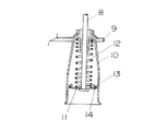
前記防振装置7の吊り棒8は、洗濯機本体6から水槽1に設けた支持片9を挿通し、この吊り棒8の下方部で、支持片9の下部には筒状のばね抑え10を設けている。
The
防振装置7は、図4に示すように構成しており、ばね支持板11は吊り棒8の下端部に設け、このばね支持板11とばね抑え10との間に圧縮コイルばね12を介装している。ばね支持板11の外周に摩擦材13を設けている。前記摩擦材13は、環状の平板に成形したゴム体と、このゴム体内部に設けたリング状のばね体14とで構成している。このゴム体の径、厚さ、表面状態、ばね体の種類等を適切に選択して組み合わせることによって摩擦材13のばね抑え10に対する摩擦力を自由に設定し上下に摺動した際に減衰作用をさせている。
The
一方、図3において洗濯機本体6の上部には上部枠体13を設けており、この上部枠体13には衣類投入時に開閉する蓋14を後方で軸支している。安全スイッチ15は上部枠体13の内部に装着し、蓋14の開閉に応じてオン、オフするものである。また、安全スイッチ15は下方に水槽1の異常振動を検知する異常振動検知レバー16を備えており、製品の移動や転倒などを事前に検知し、脱水回転数が高くならないうちに脱水動作を止める検知機能を有している。
On the other hand, in FIG. 3, an
一般に全自動洗濯機においては、洗濯し排水した後に脱水行程へと移るが、脱水行程はモータのオン、オフを繰り返し行いながら洗濯物17から水分を少しずつ出し、脱水回転数をある程度まで徐々に高めて行く、いわゆる間欠脱水動作を行いその後連続脱水を行うのが通常である。これは洗濯物17からの洗剤液が急激に排出され、発泡による洗濯兼脱水槽2の回転不良即ちモータ3への過負荷を防止する為である。
Generally, in a fully automatic washing machine, after washing and draining, the process proceeds to a dehydration process. In the dehydration process, water is gradually discharged from the
脱水行程への移行時に洗濯物17がアンバランス状態になった場合、前記間欠脱水の初期に水槽1が大きく揺れ、前記安全スイッチ15の異常振動検知レバー16を叩き、洗濯物17のアンバランス状態を検知して脱水運転を停止する構成になっている。
従来から脱水行程時の洗濯物のアンバランス状態を検知するための方法として、間欠脱水初期に水槽1が安全スイッチ15の異常振動検知レバー16の方向に揺れるように、洗濯機本体6内側にスポンジ18等を貼付けて水槽1の揺れを調整していた。
Conventionally, as a method for detecting the unbalanced state of the laundry during the dehydration process, a sponge is formed inside the
しかし間欠脱水動作の初期を通過すると、水槽1の振れまわりが小さくなり、洗濯物17のアンバランス状態を検知ができなくなる。したがって間欠脱水初期を通り過ぎた後に洗濯物が崩れてアンバランス状態になると、水槽1は洗濯機本体6に激しく衝突するなどの異常振動が発生する可能性があった。
However, when passing through the initial stage of the intermittent dewatering operation, the swing around the water tank 1 becomes small, and the unbalanced state of the
従来は洗濯行程の最後に攪拌翼5を小刻みに反転し、衣類のアンバランス状態を解消する水流を設けていたが、最近は洗濯物17の多様化と脱水時間の延長化により、脱水前や途中で使用者が洗濯物17を取出したりする可能性が増加してきた。
Conventionally, at the end of the washing process, the
例えば、使用者が洗濯物17を洗濯兼脱水槽2中央に高く重ねて投入したり、通常の洗濯物17の上にタオルケットの比較的大きな洗濯物を中央に投入した場合など、脱水回転数が300rpm程度まで上がると、タオルケットなどが遠心力により洗濯兼脱水槽2の片側に急激に移動し,脱水途中でアンバランス状態になる場合があり、脱水回転数が高まった時点で衣類のアンバランスが生じると、本来異常振動防止のため脱水運転を停止しなければならない脱水回転数以上の高回転数で運転してしまう危険状態になる。
For example, when the user puts the
上記のように、従来の方法では、間欠脱水動作の運転の初期を通り過ぎた後に洗濯物がアンバランス状態になった場合、それを検知できず、異常振動になり、水槽が激しく洗濯機本体に衝突し、異常騒音の発生や、本体または水槽の破損という不具合発生の可能性があった。 As described above, in the conventional method, when the laundry becomes unbalanced after passing through the initial stage of the intermittent dehydration operation, it cannot be detected, abnormal vibration occurs, and the water tank is intensely attached to the washing machine body. There was a possibility of occurrence of troubles such as generation of abnormal noise and damage to the main body or water tank.
本発明は前記従来の課題を解決するもので、万が一間欠脱水動作の運転初期を通り過ぎた後に洗濯物がアンバランス状態になってもそれを検知することが可能となり、異常振動の発生しない洗濯機を提供することを目的とする。 The present invention solves the above-described conventional problems, and it is possible to detect even if the laundry becomes unbalanced after passing through the initial operation of the intermittent dewatering operation, and the washing machine does not generate abnormal vibration. The purpose is to provide.
前記従来の課題を解決するために、本発明の洗濯機は、水槽を洗濯機本体上部の四隅より垂下弾性保持する4本の防振装置と、前記上部外装体内部に設けた前記水槽の異常振幅を接触感知する安全装置を設け、前記防振装置は、吊り棒と、前記吊り棒下端に配設したばね支持板と、前記ばね支持板の外周に設けた摩擦材が摺動する筒状のばね抑えと、前記支持板と前記ばね抑えとの間に設けた圧縮コイルばねとを備え、前記安全装置は、前記洗濯機本体の略コーナー部に配置し、前記安全装置を配置したコーナーおよびその対角に配置する防振装置の圧縮コイルばねの自由長を、他の2本の圧縮コイルばねの自由長より短くし、洗濯工程では、前記4本の防振装置の圧縮コイルばねが全圧縮状態で前記水槽を支持し、脱水工程時に、前記安全装置を配置したコーナーおよびその対角に配置した防振装置で支える荷重が、他の2本の防振装置より小さくなるようにしたものである。 In order to solve the above-described conventional problems, the washing machine of the present invention includes four vibration isolators that elastically hold the water tank from the four corners of the upper part of the washing machine main body, and an abnormality of the water tank provided inside the upper exterior body. Provided with a safety device that senses contact with the amplitude, the vibration isolator has a cylindrical shape on which a suspension rod, a spring support plate disposed at the lower end of the suspension rod, and a friction material provided on the outer periphery of the spring support plate slide. And a compression coil spring provided between the support plate and the spring restraint, wherein the safety device is disposed at a substantially corner portion of the washing machine body, and a corner where the safety device is disposed and The free lengths of the compression coil springs of the vibration isolator arranged at the diagonal are made shorter than the free lengths of the other two compression coil springs, and the compression coil springs of the four vibration isolation devices are all in the washing process. Supports the water tank in a compressed state, and the safety during the dehydration process Load support in vibration damping device arranged in a corner and its diagonally arranging the location is what you smaller than the other two anti-vibration device.
これによって、脱水時には、脱水兼洗濯槽内に衣類の偏りが生じ水槽が振れまわる際、水槽は支えている荷重の小さい、即ち圧縮コイルばねの自由長の短い方の防振装置側に倒れやすくなるので、間欠脱水動作の運転の初期の後にアンバランス状態になった時、その振動の揺れ方向を洗濯機本体のコーナー部に設けた安全スイッチの異常振動検知レバー側に強制することが可能となるので、水槽が激しく洗濯機本体に衝突する前に、洗濯物の片寄りを検知できる。 As a result, at the time of dehydration, when the clothes are biased in the dehydrating and washing tub and the water tub is shaken, the water tub tends to fall to the side of the vibration isolator having a smaller supporting load, that is, the shorter free length of the compression coil spring. Therefore, when it becomes an unbalanced state after the initial operation of intermittent dewatering operation, it is possible to force the direction of vibration to the abnormal vibration detection lever side of the safety switch provided at the corner of the washing machine body Therefore, before the water tank violently collides with the washing machine body, it is possible to detect the deviation of the laundry.
本発明の洗濯機は、脱水工程時に洗濯物がアンバランス状態になった場合でも、水槽の揺れ方向を安全スイッチ側に強制することが可能となり、異常振動の発生を防止することができる。 Washing machine of the present invention can be laundry during the dehydration step even if it becomes unbalanced state, it is possible to force the swing direction of the water tub to the safety switch side, to prevent the occurrence of abnormal vibration.
本発明の請求項1記載の発明は、洗濯機本体と、前記洗濯機本体の上方を覆う上部外装体と、前記洗濯機本体内部に設けた洗濯兼脱水槽を内蔵した水槽と、前記水槽を前記洗濯機本体上部の四隅より垂下弾性保持する4本の防振装置と、前記上部外装体内部に設けた前記水槽の異常振幅を接触感知する安全装置とを備え、前記防振装置は、吊り棒と、前記吊り棒下端に配設したばね支持板と、前記ばね支持板の外周に設けた摩擦材が摺動する筒状のばね抑えと、前記支持板と前記ばね抑えとの間に設けた圧縮コイルばねとを備え、前記安全装置は、前記洗濯機本体の略コーナー部に配置し、前記安全装置を配置したコーナーおよびその対角に配置した防振装置の圧縮コイルばねの自由長を、他の2本の圧縮コイルばねの自由長より短くし、洗濯工程では、前記4本の防振装置の圧縮コイルばねが全圧縮状態で前記水槽を支持し、脱水工程時に、前記安全装置を配置したコーナーおよびその対角に配置した防振装置で支える荷重が、他の2本の防振装置より小さくなるようにしたことにより、脱水工程での水槽を支える荷重を変えたものであり、これによって、脱水時脱水兼洗濯槽内に衣類の偏りが生じ水槽が振れまわる際、水槽は支えている荷重の小さい、即ち圧縮コイルばねの自由長の短い方の防振装置側に倒れやすくなるので、間欠脱水動作の運転の初期を通り過ぎた後にアンバランス状態になった時、水槽の振動の揺れ方向を洗濯機本体のコーナー部に設けた安全スイッチの異常振動検知レバー側に強制することが可能となる。 The invention according to claim 1 of the present invention includes a washing machine body, an upper exterior body that covers the washing machine body, a water tank containing a washing and dewatering tank provided inside the washing machine body, and the water tank. comprising four and vibration damping device for holding the washing machine suspended from the upper body of the four corners resilient, safety devices and for sensing contact with abnormal amplitude of the tub which is provided inside the upper exterior body, said vibration damping device, hanging and bars, provided between the spring support plate which is disposed on the suspension rod lower end, a tubular spring suppressing the friction material provided on the outer periphery of the spring support plate is slid, with said spring restrained between said support plate and a compression coil springs, said safety device, the free length of the compression coil spring substantially disposed in a corner portion, the vibration damper is arranged in a corner and its diagonally disposed the safety device of the washing machine main body , shorter than the free length of the other two of the compression coil spring, washed In the process, the compression coil springs of the four anti-vibration devices support the water tank in a fully compressed state, and the load supported by the anti-vibration devices arranged at the corners and the corners where the safety devices are arranged during the dehydration process. The load that supports the aquarium in the dehydration process is changed by making it smaller than the other two vibration isolator , and this causes a bias in clothing in the dehydrating and washing tub during dehydration. Since the water tank tends to fall to the side of the vibration isolator with the smaller load, i.e. the shorter free length of the compression coil spring, the water tank becomes unbalanced after passing through the initial stage of intermittent dehydration operation. When this happens, the vibration direction of the water tank can be forced to the abnormal vibration detection lever side of the safety switch provided at the corner of the washing machine body.
したがって水槽が激しく洗濯機本体に衝突する前に、洗濯物の片寄りを検知できるので、水槽が激しく洗濯機本体に衝突し、異常騒音の発生や、本体または水槽の破損を防止する事ができる。 Therefore, since the misalignment of the laundry can be detected before the aquarium violently collides with the washing machine body, the aquarium violently collides with the washing machine body and can prevent the occurrence of abnormal noise and the damage of the body or the aquarium. .
本発明の請求項2記載の発明は、洗濯機本体と、前記洗濯機本体の上方を覆う上部外装体と、前記洗濯機本体内部に設けた洗濯兼脱水槽を内蔵した水槽と、前記水槽を前記洗濯機本体上部の四隅より垂下弾性保持する4本の防振装置と、前記上部外装体内部に設けた前記水槽の異常振幅を接触感知する安全装置とを備え、前記防振装置は、吊り棒と、前記吊り棒下端に配設したばね支持板と、前記ばね支持板の外周に設けた摩擦材が摺動する筒状のばね抑えと、前記支持板と前記ばね抑えとの間に設けた圧縮コイルばねとを備え、前記安全装置は、前記洗濯機本体の略コーナー部に配置し、前記安全装置を配置したコーナーおよびその対角に配置した防振装置の圧縮コイルばねのばね定数を、他の2本の圧縮コイルばねのばね定数より小さくし、洗濯工程では、前記4本の防振装置の圧縮コイルばねが全圧縮状態で前記水槽を支持し、脱水工程時に、前記安全装置を配置したコーナーおよびその対角に配置した防振装置で支える荷重が、他の2本の防振装置より小さくなるようにしたことにより、脱水工程での水槽を支える荷重を変えたものであり、これによって、脱水時脱水兼洗濯槽内に衣類の偏りが生じ水槽が振れまわる際、水槽は支えている荷重の小さい、即ち圧縮コイルばね定数の小さい対角方向に揺れやすくなるので、間欠脱水動作の運転の初期を通り過ぎた後にアンバランス状態になった時、水槽の振動の揺れ方向を洗濯機本体のコーナー部に設けた安全スイッチの異常振動検知レバー側に強制することが可能となる。
The invention according to
したがって水槽が激しく洗濯機本体に衝突する前に、洗濯物の片寄りを検知できるので、水槽が激しく洗濯機本体に衝突し、異常騒音の発生や、本体または水槽の破損を防止する事ができる。 Therefore, since the misalignment of the laundry can be detected before the aquarium violently collides with the washing machine body, the aquarium violently collides with the washing machine body and can prevent the occurrence of abnormal noise and the damage of the body or the aquarium. .
以下、本発明の実施の形態について、図面を参照しながら説明する。なお、この実施の形態によって本発明が限定されるものではない。 Hereinafter, embodiments of the present invention will be described with reference to the drawings. In addition, this invention is not limited by this embodiment.
(実施の形態1)
図1は、本発明の第1の実施の形態における洗濯機の分解斜視図を示すものである。図
1において、洗濯機本体19と、前記洗濯機本体19の上方を覆う上部外装体20と、前記洗濯機本体19内部に洗濯兼脱水槽21を回転自在に軸支した水槽22を配する。前記水槽22は、4本の防振装置23にて洗濯機本体19上部の四隅より垂下保持される。
(Embodiment 1)
FIG. 1 is an exploded perspective view of a washing machine according to the first embodiment of the present invention. In FIG. 1, a washing machine
前記上部外装体20には、衣類のアンバランス状態などで前記洗濯兼脱水槽21が回転した際、水槽22が異常振れ回りして所定の振幅以上振れた時に水槽22に接触感知する異常振動検知レバー24を下方に延設した安全装置25を配設する。
In the upper
前記防振装置23の構成は、図2に示すように、吊り棒26と、吊り棒26下端に配設したばね支持板27と、前記ばね支持板27の外周に設けた摩擦材28が摺動する筒状のばね抑え29と、前記ばね支持板27と前記ばね抑え29との間に圧縮コイルばね30を配したものである。
As shown in FIG. 2, the
前記安全装置25は、洗濯機本体19に向かって左後方の略コーナー部に設け、安全装置の有するコーナーと、その対角に有する防振装置23の圧縮コイルばね30の長さを、他の2本の圧縮コイルばねより短くしたものである。この構成は、圧縮コイルばねの線材材質および線材直径、コイル径と、コイル巻き数等を同じに設定して、自由長を変えることにより構成する。
The
そして、図1において、圧縮コイルばね30の自由長を短くした防振装置23aと23bは、安全装置25を有する左後方のコーナー部と、その対角である右前方のコーナー部に配置する。
In FIG. 1, the
以上のように構成された洗濯機について、以下その動作、作用を説明する。まず、洗濯工程では、洗濯兼脱水槽21および水槽22に水が入っているので水の重量により圧縮コイルばね30は全圧縮状態となり、圧縮コイルばね30の長さの影響は無い。
About the washing machine comprised as mentioned above, the operation | movement and an effect | action are demonstrated below. First, in the washing process, since water is contained in the washing / dehydrating
しかし脱水工程に移行すると、水槽22内の洗濯水は排水されるので、圧縮コイルばねの反力により水槽22は上方に持ち上げられるが、水槽22の荷重は主に圧縮コイルばね30の自由長の長い方の防振装置23cと23dに支えられる。従って水槽22は、脱水時振れまわりの際、支える荷重の小さい、即ち圧縮コイルばね30の短い方の防振装置23aと23b側に倒れやすくなり、そこで、圧縮コイルばね30の短い防振装置23aと23bを対角線上に配置した場合、水槽はその対角方向に振れやすくなる。
However, since the washing water in the
安全装置25は、洗濯機本体19の略コーナー部(左後ろ)に設けられているから、間欠脱水動作の運転の初期の後にアンバランス状態になった時、激しく水槽22が振動をはじめるが、その振動の揺れ方向を洗濯機本体19のコーナー部に設けた安全装置25の異常振動検知レバー24側に強制することが可能となる。従って、水槽22が激しく洗濯機本体19に衝突する前に、洗濯物の片寄りを検知できる。
Since the
(実施の形態2)
本発明の第2の実施の形態における図は、第1の実施の形態における図1および図2と同一である。
(Embodiment 2)
The figure in the second embodiment of the present invention is the same as FIG. 1 and FIG. 2 in the first embodiment.
本発明は、安全装置25の有するコーナー部とその対角に有する防振装置23の圧縮コイルばね30のばね定数を他の2本の圧縮コイルばねのばね定数より小さくしたものである。この構成は、圧縮コイルばねのコイル径と自由長を同一にして、コイル巻き数あるいは線材材質および線材直径に差を設けることにより、ばね定数を変えることが出来る。
In the present invention, the spring constant of the
脱水工程では、水槽22の荷重は主に圧縮コイルばね30ばね定数の大きい方の防振装
置23cと23dに支えられる。従って脱水工程では、水槽22は脱水振れまわりの際、支える荷重の小さい、圧縮コイルばね30のばね定数の小さい方の防振装置23aと23b側に倒れやすくなり、水槽22は圧縮コイルばね30の定数の小さい対角方向に揺れやすくなる。
In the dehydration process, the load of the
よって、間欠脱水動作の運転の初期の後にアンバランス状態になった時、激しく水槽22が振動をはじめるが、その振動の揺れ方向を洗濯機本体19のコーナー部に設けた安全装置25の異常振動検知レバー24側に強制することが可能となる。従って、水槽22が激しく洗濯機本体19に衝突する前に、洗濯物の片寄りを検知できる。
Therefore, when the
(実施の形態3)
本発明の第3の実施の形態における図は、第1の実施の形態における図1および図2と同一である。
(Embodiment 3)
The figure in the third embodiment of the present invention is the same as FIG. 1 and FIG. 2 in the first embodiment.
本発明は、安全装置25の有するコーナー部とその対角に有する防振装置23の吊り棒26の長さを他の2本のつり棒の長さより長くしたものである。この構成は、圧縮コイルばね30を4個とも同じ設定とし、吊り棒26の長さを変えるものであり、水槽22を垂下支持した時の防振装置の受ける荷重が、吊り棒26長さに反比例して変わる。
In the present invention, the corners of the
脱水行程では、水槽22の荷重は主に短い吊り棒26の防振装置23cと23d側に支えられる。従って脱水工程では、水槽22は脱水振れまわりの際、支える荷重の小さい側、即ち長い吊り棒の防振装置23aと23b側に倒れやすくなり、水槽22は長い吊り棒防振装置とその対角方向に揺れやすくなる。
In the dehydration process, the load of the
よって、間欠脱水動作の運転の初期の後にアンバランス状態になった時、激しく水槽22が振動をはじめるが、その振動の揺れ方向を洗濯機本体19のコーナー部に設けた安全装置25の異常振動検知レバー24側に強制することが可能となり、水槽22が激しく洗濯機本体19に衝突する前に、洗濯物の片寄りを検知できる。
Therefore, when the
以上のように、本発明にかかる洗濯機は、複数の防振装置の仕様の組合せにより簡単に異常振動の防止が可能となるので、アンバランスを生じる回転体を防振支持する脱水装置のような機器の防振装置等の用途にも適用できる。 As described above, the washing machine according to the present invention can easily prevent abnormal vibrations by combining the specifications of a plurality of vibration isolator devices, so that the washing machine according to the present invention is like a dewatering device that supports the anti-vibration rotating body that is anti-vibrated. It can also be applied to applications such as anti-vibration devices for various equipment.
19 洗濯機本体
20 上部外装体
21 洗濯兼脱水槽
22 水槽
23 防振装置
24 異常振動検知レバー
25 安全装置
26 吊り棒
27 ばね支持板
28 摩擦材
29 ばね抑え
30 圧縮コイルばね
DESCRIPTION OF
Claims (2)
Priority Applications (3)
| Application Number | Priority Date | Filing Date | Title |
|---|---|---|---|
| JP2006249079A JP4301272B2 (en) | 2006-09-14 | 2006-09-14 | Washing machine |
| CN200710151501XA CN101144242B (en) | 2006-09-14 | 2007-09-14 | Washing machine |
| CNU2007201744688U CN201121263Y (en) | 2006-09-14 | 2007-09-14 | Washing machine |
Applications Claiming Priority (1)
| Application Number | Priority Date | Filing Date | Title |
|---|---|---|---|
| JP2006249079A JP4301272B2 (en) | 2006-09-14 | 2006-09-14 | Washing machine |
Publications (3)
| Publication Number | Publication Date |
|---|---|
| JP2008067902A JP2008067902A (en) | 2008-03-27 |
| JP2008067902A5 JP2008067902A5 (en) | 2008-05-08 |
| JP4301272B2 true JP4301272B2 (en) | 2009-07-22 |
Family
ID=39206958
Family Applications (1)
| Application Number | Title | Priority Date | Filing Date |
|---|---|---|---|
| JP2006249079A Expired - Fee Related JP4301272B2 (en) | 2006-09-14 | 2006-09-14 | Washing machine |
Country Status (2)
| Country | Link |
|---|---|
| JP (1) | JP4301272B2 (en) |
| CN (2) | CN201121263Y (en) |
Cited By (1)
| Publication number | Priority date | Publication date | Assignee | Title |
|---|---|---|---|---|
| JP2013141554A (en) * | 2012-01-12 | 2013-07-22 | Panasonic Corp | Washing machine |
Families Citing this family (7)
| Publication number | Priority date | Publication date | Assignee | Title |
|---|---|---|---|---|
| JP4301272B2 (en) * | 2006-09-14 | 2009-07-22 | パナソニック株式会社 | Washing machine |
| JP2012205778A (en) * | 2011-03-30 | 2012-10-25 | Panasonic Corp | Spin dryer |
| CN102767066B (en) * | 2012-07-21 | 2017-06-23 | 青岛海尔洗衣机有限公司 | Washing machine damping assembly and washing machine |
| CN103726254B (en) * | 2013-12-06 | 2017-12-01 | 南通芯迎设计服务有限公司 | Automatic shutdown type vibrationproof rotary drum washing machine |
| CN105088607B (en) * | 2014-04-17 | 2017-08-04 | 无锡小天鹅股份有限公司 | Rotary drum washing machine |
| WO2015158022A1 (en) * | 2014-04-17 | 2015-10-22 | 无锡小天鹅股份有限公司 | Impeller type washing machine |
| CN105019191B (en) * | 2014-04-30 | 2019-11-05 | 重庆海尔洗衣机有限公司 | A kind of washing machine eccentric detection method |
Family Cites Families (2)
| Publication number | Priority date | Publication date | Assignee | Title |
|---|---|---|---|---|
| CN1570251A (en) * | 2003-07-25 | 2005-01-26 | 乐金电子(天津)电器有限公司 | Suspension arrangement for vertical washing machine |
| JP4301272B2 (en) * | 2006-09-14 | 2009-07-22 | パナソニック株式会社 | Washing machine |
-
2006
- 2006-09-14 JP JP2006249079A patent/JP4301272B2/en not_active Expired - Fee Related
-
2007
- 2007-09-14 CN CNU2007201744688U patent/CN201121263Y/en not_active Expired - Fee Related
- 2007-09-14 CN CN200710151501XA patent/CN101144242B/en not_active Expired - Fee Related
Cited By (1)
| Publication number | Priority date | Publication date | Assignee | Title |
|---|---|---|---|---|
| JP2013141554A (en) * | 2012-01-12 | 2013-07-22 | Panasonic Corp | Washing machine |
Also Published As
| Publication number | Publication date |
|---|---|
| CN101144242B (en) | 2010-07-28 |
| JP2008067902A (en) | 2008-03-27 |
| CN101144242A (en) | 2008-03-19 |
| CN201121263Y (en) | 2008-09-24 |
Similar Documents
| Publication | Publication Date | Title |
|---|---|---|
| JP4301272B2 (en) | Washing machine | |
| KR100281311B1 (en) | Drum type washing machine for reducing vibration transmission to the bottom surface and its operation method | |
| JP4857197B2 (en) | Drum washing machine | |
| JP2008067902A5 (en) | ||
| JP2755567B2 (en) | Washing tub of drum type washing machine | |
| JP2009213917A (en) | Drum washing machine | |
| JP6750162B2 (en) | Washing machine | |
| KR101654054B1 (en) | Washing Machine | |
| JP6976037B2 (en) | Washing machine | |
| JP2017056076A (en) | Drum type washing machine | |
| JP2009153651A (en) | Washing machine | |
| KR20150075676A (en) | Suspension for full automatic washiing machine | |
| WO2014147931A1 (en) | Washing machine | |
| JP7174607B2 (en) | drum washing machine | |
| JP2013013603A (en) | Washing machine | |
| KR100437781B1 (en) | device for reducing vibration in automatic washing machine | |
| JP5489104B2 (en) | Drum washing machine | |
| JP6997004B2 (en) | Drum type washing machine | |
| KR20160102831A (en) | Damping apparatus for Owashing machine | |
| JP2910205B2 (en) | Washing machine anti-vibration device | |
| JP2015043801A (en) | Drum-type washing machine | |
| JP5762057B2 (en) | Washing machine | |
| JPS63212400A (en) | Vibrationproof apparatus of dehydration washing machine | |
| JPS62236593A (en) | Vibration damping apparatus of dehydrating washing machine | |
| JPH0584387A (en) | Drum type washing machine |
Legal Events
| Date | Code | Title | Description |
|---|---|---|---|
| A521 | Written amendment |
Free format text: JAPANESE INTERMEDIATE CODE: A523 Effective date: 20080314 |
|
| A621 | Written request for application examination |
Free format text: JAPANESE INTERMEDIATE CODE: A621 Effective date: 20080314 |
|
| A977 | Report on retrieval |
Free format text: JAPANESE INTERMEDIATE CODE: A971007 Effective date: 20080718 |
|
| A131 | Notification of reasons for refusal |
Free format text: JAPANESE INTERMEDIATE CODE: A131 Effective date: 20080729 |
|
| A521 | Written amendment |
Free format text: JAPANESE INTERMEDIATE CODE: A523 Effective date: 20080926 |
|
| TRDD | Decision of grant or rejection written | ||
| A01 | Written decision to grant a patent or to grant a registration (utility model) |
Free format text: JAPANESE INTERMEDIATE CODE: A01 Effective date: 20090331 |
|
| A01 | Written decision to grant a patent or to grant a registration (utility model) |
Free format text: JAPANESE INTERMEDIATE CODE: A01 |
|
| FPAY | Renewal fee payment (event date is renewal date of database) |
Free format text: PAYMENT UNTIL: 20120501 Year of fee payment: 3 |
|
| A61 | First payment of annual fees (during grant procedure) |
Free format text: JAPANESE INTERMEDIATE CODE: A61 Effective date: 20090413 |
|
| FPAY | Renewal fee payment (event date is renewal date of database) |
Free format text: PAYMENT UNTIL: 20120501 Year of fee payment: 3 |
|
| FPAY | Renewal fee payment (event date is renewal date of database) |
Free format text: PAYMENT UNTIL: 20130501 Year of fee payment: 4 |
|
| FPAY | Renewal fee payment (event date is renewal date of database) |
Free format text: PAYMENT UNTIL: 20130501 Year of fee payment: 4 |
|
| FPAY | Renewal fee payment (event date is renewal date of database) |
Free format text: PAYMENT UNTIL: 20140501 Year of fee payment: 5 |
|
| LAPS | Cancellation because of no payment of annual fees |