JP4301069B2 - Playback device - Google Patents
Playback device Download PDFInfo
- Publication number
- JP4301069B2 JP4301069B2 JP2004134326A JP2004134326A JP4301069B2 JP 4301069 B2 JP4301069 B2 JP 4301069B2 JP 2004134326 A JP2004134326 A JP 2004134326A JP 2004134326 A JP2004134326 A JP 2004134326A JP 4301069 B2 JP4301069 B2 JP 4301069B2
- Authority
- JP
- Japan
- Prior art keywords
- playback
- repeated
- reproduction
- storage means
- storage
- Prior art date
- Legal status (The legal status is an assumption and is not a legal conclusion. Google has not performed a legal analysis and makes no representation as to the accuracy of the status listed.)
- Expired - Fee Related
Links
Images


Description
本発明は再生装置に関し、例えばディスク状記録媒体よりオーディオ信号を区間指定して繰り返し再生するものに好適な再生装置に関する。 The present invention relates to a playback apparatus, and more particularly to a playback apparatus suitable for an apparatus that repeatedly plays an audio signal by designating a section from a disk-shaped recording medium.
現在、直径を略64mmとなし、例えば楽音信号で74分以上の記録を可能となす記憶容量を備えている、小径の光ディスクが広く知られるようになった。この小径の光ディスクは、ミニディスクMD(登録商標)と呼ばれ、ピットによりデータが記録されている再生専用型と、光磁気記録(MO)方式によりデータが記録されており再生も可能な記録再生型の2種類がある。以下の説明は、記録再生型の小径光ディスク(以下、光磁気ディスクという)に関する。上記光磁気ディスクは記録容量を上げるため、トラックピッチや、記録レーザ光の記録波長或いは対物レンズのNA等が改善されてきている。 At present, a small-diameter optical disk having a diameter of about 64 mm and having a storage capacity that enables recording of, for example, a musical sound signal for 74 minutes or more has come to be widely known. This small-diameter optical disk is called a mini-disc MD (registered trademark), a read-only type in which data is recorded by pits, and a recording / reproduction in which data is recorded by a magneto-optical recording (MO) method and can be reproduced. There are two types of molds. The following description relates to a recording / reproducing small-diameter optical disk (hereinafter referred to as a magneto-optical disk). In order to increase the recording capacity of the magneto-optical disk, the track pitch, the recording wavelength of the recording laser light, the NA of the objective lens, and the like have been improved.
図14に示すように、トラックピッチ1.6μmでグルーブ記録、また変調方式がEFMである、初期の光磁気ディスクを第1世代MDと記す。この第1世代MDの物理フォーマットは、以下のように定められている。トラックピッチは、1.6μm、ビット長は、0.59μm/bitとなる。また、レーザ波長λは、λ=780nmであり、光学ヘッドの開口率は、NA=0.45としている。記録方式としては、グルーブ(ディスク盤面上の溝)をトラックとして記録再生に用いるグルーブ記録方式を採用している。また、アドレス方式は、ディスク盤面上にシングルスパイラルのグルーブを形成し、このグルーブの両側に対してアドレス情報としてのウォブル(Wobble)を形成したウォブルドグルーブを利用する方式を採っている。なお、本明細書では、ウォブリングにより記録される絶対アドレスをADIP(Address in Pregroove)ともいう。この第1世代MDは、記録データの変調方式として、EFM(8−14変換)変調方式が採用されている。また、誤り訂正方式としては、ACIRC(Advanced Cross Interleave Reed-Solomon Code)を用いている。また、データインターリーブには、畳み込み型を採用している。これにより、データの冗長度は、46.3%となっている。また、第1世代MDにおけるデータの検出方式は、ビットバイビット方式であって、ディスク駆動方式としては、CLV(Constant Linear Verocity)が採用されている。CLVの線速度は、1.2m/sである。記録再生時の標準のデータレートは133kB/s、記録容量は164MB(MD−DATAでは、140MB)である。また、データの最小書換単位(クラスタ)は、32個のメインセクタと4個のリンクセクタによる36セクタで構成されている。 As shown in FIG. 14, an initial magneto-optical disk in which groove recording is performed at a track pitch of 1.6 μm and the modulation method is EFM is referred to as a first generation MD. The physical format of the first generation MD is defined as follows. The track pitch is 1.6 μm and the bit length is 0.59 μm / bit. The laser wavelength λ is λ = 780 nm, and the aperture ratio of the optical head is NA = 0.45. As a recording system, a groove recording system that uses grooves (grooves on the disk board surface) as tracks for recording and reproduction is adopted. The address system employs a system using a wobbled groove in which a single spiral groove is formed on the disk surface and wobbles as address information are formed on both sides of the groove. In this specification, the absolute address recorded by wobbling is also referred to as ADIP (Address in Pregroove). This first generation MD employs an EFM (8-14 conversion) modulation system as a recording data modulation system. As an error correction method, ACIRC (Advanced Cross Interleave Reed-Solomon Code) is used. In addition, a convolution type is adopted for data interleaving. As a result, the data redundancy is 46.3%. The data detection method in the first generation MD is a bit-by-bit method, and CLV (Constant Linear Verocity) is adopted as the disk drive method. The linear velocity of CLV is 1.2 m / s. The standard data rate at the time of recording / reproducing is 133 kB / s, and the recording capacity is 164 MB (140 MB in MD-DATA). The minimum data rewrite unit (cluster) is composed of 36 sectors including 32 main sectors and 4 link sectors.
さらに、近年では、第1世代MDよりもさらに記録容量を上げた高密度MDが開発された。先ず、従来の媒体(ディスクやカートリッジ)はそのままに、変調方式や、論理構造などを変更してユーザエリア等を倍密度にし、記録容量を例えば300MBに増加したMD(以下、高密度MD1という)が開発された。記録媒体の物理的仕様は、同一であり、トラックピッチは、1.6μm、レーザ波長λは、λ=780nmであり、光学ヘッドの開口率は、NA=0.45である。記録方式としては、グルーブ記録方式を採用している。また、アドレス方式は、ADIPを利用する。このように、ディスクドライブ装置における光学系の構成やADIPアドレス読出方式、サーボ処理は、第1世代MDと同様である。この高密度MD1は、記録データの変調方式として、高密度記録に適合したRLL(1−7)PP変調方式(RLL;Run Length Limited、PP:Parity preserve/Prohibit rmtr(repeated minimum transition runlength))を採用している。また、誤り訂正方式としては、より訂正能力の高いBIS(Burst Indicator Subcode)付きのRS−LDC(Reed Solomon−Long Distance Code)方式を用いている。 Furthermore, in recent years, high-density MDs with higher recording capacity than the first generation MDs have been developed. First, a conventional medium (disk or cartridge) is left as it is, and the modulation method, logical structure, and the like are changed to double the user area and the like, and the recording capacity is increased to, for example, 300 MB (hereinafter referred to as high density MD1). Was developed. The physical specifications of the recording medium are the same, the track pitch is 1.6 μm, the laser wavelength λ is λ = 780 nm, and the aperture ratio of the optical head is NA = 0.45. As a recording method, a groove recording method is adopted. The address system uses ADIP. Thus, the configuration of the optical system, the ADIP address reading method, and the servo processing in the disk drive device are the same as those in the first generation MD. This high-density MD1 uses an RLL (1-7) PP modulation method (RLL: Run Length Limited, PP: Parity preserve / Prohibit rmtr (repeated minimum transition runlength)) suitable for high-density recording as a modulation method of recording data. Adopted. Further, as an error correction method, an RS-LDC (Reed Solomon-Long Distance Code) method with BIS (Burst Indicator Subcode) having higher correction capability is used.
さらに、高密度MDとしては、高密度MD1より記録容量を増加した高密度MD3が、外形、光学系は互換性を保ちながらも、トラックピッチを1.25μmに狭め、かつ例えば前記グルーブから磁壁移動検出(Domain Wall Displacement Detection:DWDD)によって記録マークを検出する方式で開発された。この高密度MD3は、記録データの変調方式として、高密度記録に適合したRLL(1−7)PP変調方式(RLL;Run Length Limited、PP:Parity preserve/Prohibit rmtr(repeated minimum transition runlength))を採用している。また、誤り訂正方式としては、より訂正能力の高いBIS(Burst Indicator Subcode)付きのRS−LDC(Reed Solomon−Long Distance Code)方式を用いている。データインターリーブは、ブロック完結型とする。これによりデータの冗長度は、20.50%になる。またデータの検出方式は、PR(1,−1)MLによるビタビ復号方式を用いる。また、データの最小書換単位であるクラスタは、16セクタ、64kBで構成されている。ディスク駆動方式にはZCAV方式を用い、その線速度は2.0m/sとする。記録再生時の標準データレートは、9.8MB/sである。したがって、高密度MD3では、DWDD方式及びこの駆動方式を採用することにより、総記録容量を1GBにできた。 Furthermore, as the high-density MD, the high-density MD3 having a larger recording capacity than the high-density MD1 has a track pitch narrowed to 1.25 μm while maintaining the compatibility of the outer shape and the optical system, and moves the domain wall from the groove, for example. It was developed by a method of detecting a recording mark by detection (Domain Wall Displacement Detection: DWDD). This high-density MD3 uses an RLL (1-7) PP modulation method (RLL: Run Length Limited, PP: Parity preserve / Prohibit rmtr (repeated minimum transition runlength)) suitable for high-density recording as a modulation method for recording data. Adopted. Further, as an error correction method, an RS-LDC (Reed Solomon-Long Distance Code) method with BIS (Burst Indicator Subcode) having higher correction capability is used. Data interleaving is a block-complete type. As a result, the data redundancy becomes 20.50%. As a data detection method, a Viterbi decoding method based on PR (1, -1) ML is used. A cluster which is the minimum data rewrite unit is composed of 16 sectors and 64 kB. A ZCAV system is used as the disk drive system, and the linear velocity is 2.0 m / s. The standard data rate at the time of recording / reproducing is 9.8 MB / s. Therefore, in the high-density MD3, the total recording capacity can be reduced to 1 GB by adopting the DWDD method and this driving method.
ところで、上記第1世代MD、高密度MD1、高密度MD3を再生する再生装置において、ある決まった区間を繰返し再生するためには、(1)開始地点と終了地点を決めて1曲とする(Divide編集を行って1曲とする)、(2)上記(1)で作った曲のみを繰返し再生(1曲Repeat再生)する、という方法があった。しかし、この方法は、編集できない曲に対しては行えない(Pre-masterd Discなど)し、また短い曲(区間)の場合に何度もディスクからの読み出しをする必要があり、その読み出しが再生の音出しに追いつかないと音が途切れることになる、という欠点があった。 By the way, in the reproducing apparatus for reproducing the first generation MD, the high density MD1, and the high density MD3, in order to repeatedly reproduce a predetermined section, (1) a start point and an end point are determined as one song ( Divide editing is used to make one song), and (2) only the song created in (1) above is repeatedly played (one song repeat playback). However, this method cannot be used for songs that cannot be edited (such as pre-mastered discs), and it is necessary to read from the disc many times for short songs (sections). There was a drawback that the sound would be interrupted if it could not keep up with the sound.
また、特開2000−293924には、アドレスAとアドレスBで再生区間を指定するとき、アドレスBまでの音声データをメモリに記憶し終わった後、アドレスBまでの再生出力をしている間、アドレスBに続いて次に再生出力する音声データを先行してメモリ18に記憶するとき、MD上のアドレスAに戻って光ピックアップによって読み取り、既に記憶したアドレスBまでの音声に続けてアドレスAからの音声データをメモリ18に記憶する構成が記載されている。
Japanese Patent Laid-Open No. 2000-293924 discloses that when a playback section is designated by address A and address B, after the audio data up to address B has been stored in the memory, playback output up to address B is being performed. When the audio data to be reproduced and output next to the address B is stored in the
ところで、上記特許文献1のような通常再生をしているとき、再生が終了したデータは不要なものとしてその部分は捨てられてしまう。そこで、一度溜め込まれたデータをバッファ内で何度も再利用することが考えられる。バッファ内で何度も再利用するためには捨ててはいけないが、再生区間がバッファの容量よりも多い場合は通常再生と同じように捨てた上で次のデータを上書する必要がある。
By the way, when normal reproduction is performed as in the above-mentioned
再生区間はユーザーが設定するためにデータ量がバッファ内部で収まるかどうかは再生区間終了位置が決まらないと判明しない。このようにバッファ内で溜め込んだデータを何度も再利用するか、或いは再生区間がバッファの容量よりも多い場合にデータを捨てた上で次のデータを上書きするかという見極めが必要である。 Since the playback section is set by the user, it cannot be determined that the end position of the playback section is determined if the amount of data fits within the buffer. In this way, it is necessary to determine whether to reuse the data accumulated in the buffer many times, or to discard the data and overwrite the next data when the playback section is larger than the buffer capacity.
本発明は、上記実情に鑑みてなされたものであり、バッファ内で溜め込んだデータを何度も再利用するか、或いは再生区間がバッファの容量よりも多い場合にデータを捨てた上で次のデータを上書きするかという見極めを容易とする再生装置の提供を目的とする。 The present invention has been made in view of the above situation, and the data accumulated in the buffer is reused many times, or when the playback section is larger than the capacity of the buffer, the data is discarded and the next It is an object of the present invention to provide a playback device that makes it easy to determine whether to overwrite data.
また、本発明は、語学学習などで短いセンテンスの繰返しを聞く場合でもトラックの分割編集をする必要がないので、ディスクへの記録機能がなくても、繰り返し指定再生が可能な再生装置の提供を目的とする。 In addition, the present invention, since there is no need to split editing of the track even if you hear the repetition of short sentences in such as language learning, even if there is no recording function to the disk, the provision of repetition designation reproduction is possible and reproducing apparatus Objective.
また、バッファ内で溜め込んだデータを何度も再利用するときには、アクセス&溜め込みの繰り返しを「一度Bufferに溜めきるまで」しか行わないので、区間再生中に「アクセスと溜め込み待ちのための音切れ」を発生させることがない再生装置の提供を目的とする。 Also, when reusing the data stored in the buffer many times, the access & storage is repeated only "until it is stored in the buffer once". It is an object of the present invention to provide a playback apparatus that does not generate “
さらに、繰返しアクセスを行わず、Buffer内再生になるのでメカ駆動がなくなることで電力的にメリットが生まれる再生装置の提供を目的とする。 Furthermore, no I rows repeated access to the provision of power to merit is born reproducing apparatus by mechanical driving is eliminated since the Buffer in reproduction.
本発明に係る再生装置は、上記課題を解決するために、ディスク状記録媒体に記録されている記録データを読み出す読み出し手段と、上記読み出し手段により読み出された記録データが溜め込まれる記憶手段と、上記記録データからなる一つのトラック内で繰り返し再生の開始地点と終了地点とで特定される区間が指定されると、当該指定繰り返し再生区間の時間的長さが上記記憶手段の所定記憶容量分の時間的長さよりも短いときに、上記記憶手段内に一度溜め込まれた記録データのみで繰り返し再生処理が行われる記憶手段内繰り返し再生処理を実行する記憶制御手段とを備え、上記記憶制御手段は、上記記憶手段内繰り返し再生処理を実行するときには、上記記憶手段内繰り返し再生処理を行うことを示すフラグをオンにしてから上記記憶手段内に記録データを溜め込むとともに、電源遮断前に上記繰り返し再生の開始地点と上記繰り返し再生の終了地点と上記フラグと上記記憶手段内繰り返し再生処理を停止したときの上記記憶手段内の再生カウンタとを不揮発性メモリに記憶し、上記記憶手段内繰り返し再生処理中に再生を停止し、電源遮断後、電源投入されたときには、上記不揮発性メモリに記憶した繰り返し再生の開始地点と繰り返し再生の終了地点と上記フラグと上記記憶手段内繰り返し再生処理を停止したときの上記記憶手段内の再生カウンタとに基づいて、再び停止した位置から再生を開始して上記指定繰り返し再生区間での上記記憶手段内繰り返し再生処理に戻る。 In order to solve the above problems, the reproducing apparatus according to the present invention includes a reading unit that reads recording data recorded on a disk-shaped recording medium, a storage unit that stores recording data read by the reading unit, When a section specified by the start point and end point of repeated playback is specified in one track composed of the recorded data, the time length of the specified repeated playback section is equal to the predetermined storage capacity of the storage means. Storage control means for executing repetitive reproduction processing in the storage means in which repetitive reproduction processing is performed only with the recording data once accumulated in the storage means when the time is shorter than the time length , the storage control means, When executing the repetitive reproduction process in the storage means, the flag indicating that the repetitive reproduction process in the storage means is performed is turned on, and then Recording data is stored in the storage means, and the playback point in the storage means when the repeated playback start point, the repeated playback end point, the flag, and the repeated playback processing in the storage means are stopped before the power is turned off. Is stored in the non-volatile memory, the playback is stopped during the repetitive playback process in the storage means, and when the power is turned on after the power is turned off, the start point of the repeated playback stored in the non-volatile memory and the end of the repeated playback are stored. Based on the point, the flag, and the reproduction counter in the storage means when the repetitive reproduction processing in the storage means is stopped, the reproduction is started again from the position where it was stopped and the storage means in the designated repeated reproduction section is started. Ru return to repeat the reproduction processing.
この再生装置は、記録データからなる一つのトラック内で繰り返し再生の開始地点と終了地点とで特定される区間が指定されると、当該指定繰り返し再生区間の時間的長さが記憶手段の所定記憶容量分の時間的長さよりも短いときには記憶手段内に一度溜め込まれた記録データを用いた記憶手段内繰り返し再生処理を実行する。 In this playback apparatus, when a section specified by a start point and an end point of repeated playback is specified in one track made of recorded data, the time length of the specified repeated playback section is stored in a predetermined storage unit. When the time length is shorter than the capacity, the repetitive reproduction process in the storage means using the recording data once stored in the storage means is executed.
本発明に係る再生装置は、記録データからなる一つのトラック内で繰り返し再生の開始地点と終了地点とで特定される区間が指定されると、当該指定繰り返し再生区間の時間的長さが記憶手段の所定記憶容量分の時間的長さよりも短いときには記憶手段内に一度溜め込まれた記録データを用いた記憶手段内繰り返し再生処理を実行するので、バッファ内で溜め込んだデータを何度も再利用するか、或いは再生区間がバッファの容量よりも多い場合にデータを捨てた上で次のデータを上書きするかという見極めを容易とする。また、語学学習などで短いセンテンスの繰返しを聞く場合でもトラックの分割編集をする必要がないので、ディスクへの記録機能のなくても、繰り返し指定再生が可能となる。また、バッファ内で溜め込んだデータを何度も再利用するときには、アクセス&溜め込みの繰り返しを「一度Bufferに溜めきるまで」しか行わないので、区間再生中に「アクセスと溜め込み待ちのための音切れ」を発生させることがない。さらに、繰返しアクセスを行わず、Buffer内再生になるのでメカ駆動がなくなることで電力的にメリットが生まれる。 The playback apparatus according to the present invention stores the time length of the designated repeated playback section when the section specified by the start and end points of repeated playback is designated in one track made of recorded data. When the time length is shorter than the predetermined storage capacity, the replay processing in the storage means using the recording data once stored in the storage means is executed, so that the data stored in the buffer is reused many times. Or, when the playback section is larger than the buffer capacity, it is easy to determine whether to discard the data and overwrite the next data. Also, even when listening to repeated short sentences in language learning or the like, it is not necessary to divide and edit tracks, so that it is possible to repeatedly specify and reproduce without a disc recording function. Also, when reusing the data stored in the buffer many times, the access and storage is repeated only "until it is stored in the buffer once". Is not generated. Furthermore, no I rows repeated access, power to merit is born by the mechanical driving is eliminated since the Buffer in reproduction.
以下、本発明を実施するための最良の形態を説明する。図1は実施の形態の光磁気ディスク再生装置1の概略構成を示す図である。この光磁気ディスク再生装置1は、例えば高密度MD1や高密度MD3のような高密度ディスク2を再生する。もちろん、第1世代MDを再生する装置に適用してもよい。
Hereinafter, the best mode for carrying out the present invention will be described. FIG. 1 is a diagram showing a schematic configuration of a magneto-optical
光磁気ディスク再生装置1は、高密度MD2に記録されている記録データを読み出すディスク読み出し部3と、所定の記憶容量を有し、ディスク読み出し部3により読み出された記録データが溜め込まれる、例えばリングバッファメモリであるDRAM12と、このDRAM12を制御するメモリコントローラ15と、DRAM12から再生されたデータをデコードするオーディオデコーダ13とを備えて成る。
The magneto-optical
メモリコントローラ15は、記録データからなる一つのトラック内で繰り返し再生の開始地点と終了地点とで特定される区間が指定されると、当該指定繰り返し再生区間の時間的長さと、DRAM12の所定記憶容量分の時間的長さとを比較し、比較結果に基づいてDRAM(バッファ)12内で再生を繰り返すモードにするか、あるいは従来どおりの繰り返しため込みによる再生を行うかを判断する。例えば、指定繰り返し再生区間の時間的長さが、DRAM12の所定記憶容量分の時間的長さよりも短いときには、DRAM12内に一度溜め込まれた記録データを用いたDRAM内繰り返し再生処理を実行する。このDRAM内繰り返し再生処理については後述する。
When a section specified by a start point and an end point of repeated playback is specified in one track made of recorded data, the
なお、本発明における区間再生は一つの曲、すなわち一つのトラック以内で行うことを前提にしている。 In the present invention, it is assumed that the section reproduction is performed within one song, that is, within one track.
図2は光磁気ディスク再生装置1の詳細な構成を示す図である。ディスク読み出し部3は、高密度MD2を回転させるためのスピンドルモータ4や、高密度MD2に記録されているデータを読み取るための光学ピックアップ5、光学ピックアップ5によって読み取られたデータからRF信号、ADIP信号、トラッキングエラー信号、フォーカスエラー信号等を生成するRFアンプ6を備える。また、RFアンプ6からのRF信号に再生信号処理を施して、DRAM12に供給する再生信号処理部9と、上記ADIPからアドレスをデコードするアドレスデコーダ10と、上記各エラー信号に基づいてトラッキングサーボ信号、フォーカスサーボ信号等のサーボ信号を生成してモータドライバ8に供給するサーボ回路7と、ドライブコントローラ11を備える。
FIG. 2 is a diagram showing a detailed configuration of the magneto-optical
再生処理系としては、高密度MD2の再生時にRLL(1−7)PP変調に対応する復調(PR(1,−1)ML及びビタビ復号を用いたデータ検出に基づくRLL(1−7)復調)、RS−LDCデコードを行う部位とが設けられる。 As a reproduction processing system, demodulation corresponding to RLL (1-7) PP modulation during reproduction of high-density MD2 (RLL (1-7) demodulation based on data detection using PR (1, -1) ML and Viterbi decoding) ) And a part for performing RS-LDC decoding.
光学ピックアップ5の高密度MD2に対するレーザ照射によりその反射光として検出された情報(フォトディテクタによりレーザ反射光を検出して得られる光電流)は、RFアンプ6に供給される。RFアンプ6では、入力された検出情報に対して電流−電圧変換、増幅、マトリクス演算等を行い、再生情報としての再生RF信号、トラッキングエラー信号TE、フォーカスエラー信号FE、グルーブ情報(高密度MD2にトラックのウォブリングにより記録されているADIP情報)等を抽出する。
Information (photocurrent obtained by detecting the laser reflected light with a photodetector) detected by the laser irradiation on the high-
次世代MD2の再生時には、RFアンプ6で得られた再生RF信号は、再生信号処理部9内のA/D変換回路、イコライザ、PLL回路、PRML回路を介して、RLL(1−7)PP復調部及びRS−LDCデコーダで信号処理される。再生RF信号は、RLL(1−7)PP復調部において、PR(1,−1)ML及びビタビ復号を用いたデータ検出によりRLL(1−7)符号列としての再生データを得て、このRLL(1−7)符号列に対してRLL(1−7)復調処理が行われる。さらに、RS−LDCデコーダにて誤り訂正及びデインターリーブ処理される。そして、復調されたデータが高密度MD2からの再生データ(圧縮データ)としてDRAM12に出力される。
At the time of reproduction of the next-generation MD2, the reproduction RF signal obtained by the
RFアンプ6から出力されるトラッキングエラー信号TE、フォーカスエラー信号FEは、サーボ回路7に供給され、グルーブ情報は、アドレスデコータ10に供給される。
The tracking error signal TE and the focus error signal FE output from the
アドレスデコータ10は、グルーブ情報に対してバンドパスフィルタにより帯域制限してウォブル成分を抽出した後、FM復調、バイフェーズ復調を行ってADIPアドレスを抽出する。抽出された、ディスク上の絶対アドレス情報であるADIPアドレスは、高密度MD2アドレスとされてドライブコントローラ11に供給される。
The
ドライブコントローラ11では、ADIPアドレスに基づいて、所定の制御処理を実行する。またグルーブ情報は、スピンドルサーボ制御のためにサーボ回路7に戻される。 The drive controller 11 executes predetermined control processing based on the ADIP address. The groove information is returned to the servo circuit 7 for spindle servo control.
サーボ回路7は、例えばグルーブ情報に対して再生クロック(デコード時のPLL系クロック)との位相誤差を積分して得られる誤差信号に基づき、ZCAVサーボ制御のためのスピンドルエラー信号を生成する。 The servo circuit 7 generates a spindle error signal for ZCAV servo control, for example, based on an error signal obtained by integrating a phase error with a reproduction clock (PLL clock at the time of decoding) with respect to groove information.
またサーボ回路7は、スピンドルエラー信号や、上記のようにRFアンプ6から供給されたトラッキングエラー信号、フォーカスエラー信号、或いはドライブコントローラ11を介したシステムコントローラ16からのトラックジャンプ指令、アクセス指令等に基づいて各種サーボ制御信号(トラッキング制御信号、フォーカス制御信号、スレッド制御信号、スピンドル制御信号等)を生成し、モータドライバ8に対して出力する。すなわち、上記サーボエラー信号や指令に対して位相補償処理、ゲイン処理、目標値設定処理等の必要処理を行って各種サーボ制御信号を生成する。
Further, the servo circuit 7 responds to a spindle error signal, a tracking error signal supplied from the
モータドライバ8では、サーボ回路7から供給されたサーボ制御信号に基づいて所定のサーボドライブ信号を生成する。ここでのサーボドライブ信号としては、2軸機構を駆動する2軸ドライブ信号(フォーカス方向、トラッキング方向の2種)、スレッド機構を駆動するスレッドモータ駆動信号、スピンドルモータ4を駆動するスピンドルモータ駆動信号となる。このようなサーボドライブ信号により、高密度MD2に対するフォーカス制御、トラッキング制御、及びスピンドルモータ4に対するZCAV制御が行われる。
The
DRAM12は、ディスク読み出し部3から供給される圧縮データを保持し、これをバッファリングする。そして、バッファリングした圧縮データをシステムコントローラ16からのコマンドによってメモリ制御を行うメモリコントローラ15の制御の下にオーディオデコーダ13に対して出力する。
The
オーディオデコーダ13は、DRAM12から入力された圧縮データについての伸長処理を行うことによりデジタルオーディオデータを生成する。そして、このように生成されたデジタルオーディオデータは出力端子14から図示しないA/D変換器を介することによりアナログのオーディオ信号に変換され、オーディオ出力として再生出力される。
The
このように光磁気ディスク再生装置1は、高密度MD2から読み出したデータを一度DRAM12にバッファリングしてから再生出力するように構成されている。
As described above, the magneto-optical
システムコントローラ16には、操作部17が接続されている。操作部17は、図3に示すように、操作パネル上に、プレイキー21、ポーズキー22、停止キー23、ファーストフォワードFFキー24、ファーストリバースFRキー25を備えている。また、記録データからなる一つのトラック内で繰り返し再生の開始地点Aと終了地点Bとで特定される区間A−Bをリピートするための操作キー26と、開始地点Aの状態表示灯27、終了地点Bの状態表示灯28を備える。さらに、操作部17の操作パネルには、液晶表示部29が設けられ、バッテリーの残量表示30や、A−Bリピートに関する表示を行っている。
An
これらの構成の中で、メモリコントローラ15は、システムコントローラ16からのコマンドにしたがって、記録データからなる一つのトラック内で繰り返し再生の開始地点と終了地点とで特定される区間が指定されると、当該指定繰り返し再生区間の時間的長さがDRAM12の所定記憶容量分の時間的長さよりも短いときに、DRAM12内に一度溜め込まれた記録データを用いたDRAM内繰り返し再生処理を実行する。また、メモリコントローラ15は、DRAM内繰り返し再生処理を実行するときには、DRAM12内の溜め込み開始位置を上書きしないように、その手前まで上記一つのトラック内の記録データを溜め込む。また、メモリコントローラ15は、繰り返し再生の終了地点の記録データが溜め込まれているDRAM12内の溜め込み終了位置から上記繰り返し再生の開始地点の記録データを上記溜め込み開始位置の手前まで溜め込む。
In these configurations, the
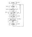
図4は操作部17を用いたユーザの操作に対応したシステムコントローラ16の処理手順を示すフローチャートである。例えば、図3に示したA−Bリピートキー26が一度押され、区間再生モードが選択され(ステップS1)、開始地点Aが決定されると(ステップS2)、現在再生中であるか否かをステップS3にてチェックする。現在再生中でなければステップS4にて再生を開始し、ステップS5に進む。現在再生中であれば、ステップS5に直接進む。
FIG. 4 is a flowchart showing a processing procedure of the
ステップS5では、トラックの切れ目であるか否かをチェックする。トラックの切れ目であれば、ユーザにより終了地点決定操作が行われなくてもステップS7にて終了地点を決定する。トラックの切れ目でなければ、ユーザによる終了地点決定操作が行われたか否かをステップS6にてチェックする。ステップS6にて終了地点決定操作が行われたのであればステップS7に進んで終了地点を決定する。ステップS6にて終了地点決定操作が行われていないのであればステップS5からの処理に戻る。ステップS7にて終了地点を決定するとステップS8にて区間再生処理を開始する。 In step S5, it is checked whether or not there is a track break. If it is a track break, the end point is determined in step S7 even if the end point determination operation is not performed by the user. If it is not a track break, it is checked in step S6 whether or not an end point determination operation has been performed by the user. If the end point determination operation is performed in step S6, the process proceeds to step S7 to determine the end point. If the end point determination operation is not performed in step S6, the process returns to step S5. When the end point is determined in step S7, the section reproduction process is started in step S8.
図5はディスク読み出し部3にて読み出された圧縮データをDRAM12に溜め込むときのシステムコントローラ16の処理手順を示すフローチャートである。ステップS11にて区間再生モードが選択され、ステップS12にて開始地点が決定されると、ステップS13にてアドレス保持レジスタ内に開始地点Aのディスク上のアドレスを保持する。また、ステップS14にて終了地点Bが決定されると、ステップS15にてアドレス保持レジスタ内に終了地点Bのディスク上のアドレスを保持する。
FIG. 5 is a flowchart showing a processing procedure of the
次にシステムコントローラ16は、メモリコントローラ15にDRAM12内で区間再生が実現可能であるか否かをチェックさせる。メモリコントローラ15は、システムコントローラ16からのコマンドにしたがって、記録データからなる一つのトラック内で繰り返し再生の開始地点と終了地点とで特定される区間が指定されると、当該指定繰り返し再生区間の時間的長さと、DRAM12の所定記憶容量分の時間的長さとを比較することにより、DRAM12内で区間再生が実現可能であるか否かをチェックする(ステップS16)。
Next, the
ステップS16にて上記記録データからなる一つのトラック内で繰り返し再生の開始地点と終了地点とで特定される区間の時間的長さが、DRAM(バッファ)12の所定記憶容量分の時間的長さよりも短いと判断すれば、バッファ内での区間再生実現可能とし、ステップS17にてバッファ内区間再生のフラグをonにする。その後、ステップS18にて開始〜終了区間を繰り返しバッファ内に溜め込む。ステップS16にて繰り返し再生の開始地点と終了地点とで特定される区間の時間的長さが、DRAM(バッファ)12の所定記憶容量分の時間的長さよりも長いと判断すれば、直接ステップS18に進んで、開始〜終了区間を繰り返しバッファ内に溜める。 In step S16, the time length of the section specified by the start point and the end point of repeated reproduction in one track made of the recording data is larger than the time length corresponding to the predetermined storage capacity of the DRAM (buffer) 12. If it is determined that the period is shorter, the section playback in the buffer can be realized, and the section playback flag in the buffer is turned on in step S17. Thereafter, in step S18, the start-end section is repeatedly stored in the buffer. If it is determined in step S16 that the time length of the section specified by the start point and the end point of repeated playback is longer than the time length corresponding to the predetermined storage capacity of the DRAM (buffer) 12, the process directly goes to step S18. Then, the start-end section is repeatedly accumulated in the buffer.
ステップS19では、バッファ内区間再生フラグがonであるか否かをチェックし、上記再生フラグがonであると判断すると、バッファ内区間再生処理を行うのであるから、バッファ内残量監視モニタを一時停止してから溜め込み処理を終了する。ステップS19にてバッファ内区間再生フラグがoffであると判断すると、そのまま溜め込み処理を終了する。 In step S19, it is checked whether or not the in-buffer section playback flag is on. If it is determined that the above-mentioned playback flag is on, the in-buffer section playback processing is performed. After stopping, the accumulation process is terminated. If it is determined in step S19 that the in-buffer section reproduction flag is off, the accumulation process is terminated as it is.
図6はDRAM12からメモリコントローラ15に圧縮データを再生させるシステムコントローラ16の処理手順を示すフローチャートである。ステップS21にてDRAM12の開始点Aから再生処理を開始すると、ステップS22では再生を継続し、ステップS23にて区間終了地点Bになったか否かをチェックする。ステップS23にて区間終了地点Bであることを判定すると、ステップS24にてバッファ内区間再生フラグonになっているか否かをチェックする。バッファ内区間再生フラグonであると判定すると、ステップS25にて再生を一時停止してから、ステップS26に進み再生カウンタをバッファ内の開始地点Aに設定し、ステップS27にて再生を再開する。
FIG. 6 is a flowchart showing a processing procedure of the
図7はバッファ内区間再生処理の具体例を示す図である。上記図4のステップS2にて操作部17のA−Bリピートキー26が操作され、開始地点Aが決定される。その後、ステップS3〜ステップS6が処理され、ステップS7にてA−Bリピートキー26が操作されて終了地点Bが決定される。ただし、ステップS5の分岐にてトラックの切れ目でないことが判定され、ステップS6にて終了地点決定操作が行われてBが決定された場合の他、ステップS5にてトラックの切れ目であることを判定した場合にはA−Bリピートキー26の操作がなくてもトラックの切れ目を終了地点Bとする場合がある。
FIG. 7 is a diagram showing a specific example of the intra-buffer section reproduction process. In step S2 of FIG. 4, the
システムコントローラ16は、図5のステップS16にてバッファ内で区間再生実現が可能であるか否かをチェックする。具体的には、先ずトラック1の開始点Aのディスク上のアドレスPAと終了点BのアドレスPBから再生区間PA〜PBの時間的長さTA−Bを求める。もちろん、データの圧縮率や、データの離散的な記録についても考慮に入れる。次に、DRAM12のバッファエリアの所定記憶容量分の時間的長さTbufferも、データの圧縮率を考慮して求める。そして、再生区間PA〜PBの時間的長さTA−Bとバッファエリアの所定記憶容量分の時間的長さTbufferを比較する。再生区間PA〜PBの時間的長さTA−Bがバッファエリアの所定記憶容量分の時間的長さTbufferよりも短ければ、バッファ内での区間再生が可能であるので、図5のステップS17に進む。
In step S16 in FIG. 5, the
図7に示す状態には、操作部17上に設けた、開始地点Aの状態表示灯27、終了地点Bの状態表示灯28の消灯、点滅、点灯状態を示す。区間再生モードに入るとA地点が決定されるまで状態表示灯27が点滅し、状態表示灯28は消灯している。A地点が決定されると状態表示灯27が点灯し、B地点決定待ちを促すために状態表示灯28が点滅する。B地点が決定されると状態表示灯28も点灯する。
In the state shown in FIG. 7, the
図8及び図9は、バッファ内区間再生処理が可能か否かを判定する(図5のステップS16)の具体例を示す図である。再生区間A−Bが確定した時点で、システムコントローラ16はメモリコントローラ15にバッファコントロール信号(Buffer_ctl)をださせ、DRAM内リピートするか、DRAM内リピートしないかを判断する。その判断は、A−Bリピートため込みを開始する直前にA地点とB地点のアドレスから、A−B区間の消費ブロック数(セクタ数)を計算する。消費ブロックが上記DRAMの所定の記憶容量に対応する閾値(in_dram_thd)以上だった場合には、DRAM内再生をせず、通常のA−Bリピート動作を行う。消費ブロックが閾値(in_dram_thd)未満だった場合には、DRAM内再生を行うべく、DRAM内でその情報を保持する。さらに具体的には、高密度MDの場合に計算したブロック数が、DRAMの総容量の3分の2よりも小さいときには、DRAM内リピート可能とする。
8 and 9 are diagrams showing a specific example of determining whether or not the in-buffer section reproduction process is possible (step S16 in FIG. 5). When the playback section A-B is determined, the
以下には、DRAM内再生を行うときのシステムコントローラ16の処理について図8及び図9を参照して説明する。DRAM内再生を行うとき、システムコントローラ16はメモリコントローラ15にバッファコントロール信号(Buffer_ctl)をださせ、DRAM内にある程度空きを残した状態でA−B区間を溜め込む。これは、DRAMの先頭にため込まれているA地点のデータを上書きしてしまわないためである。また、ため込みはフラグをたててから開始する。これは、スリープからの復帰でDRAM内繰り返し区間再生と通常区間再生を区別するためである。また、DRAM内再生モードの場合、システムコントローラ16は、DRAM残量監視を一時停止する。
Hereinafter, the processing of the
再生については、システムコントローラ16は、DRAMの先頭にため込まれたA−B区間のデータをリピート再生する。B地点まで再生したら、一旦、再生を停止させ、カウンタを先頭のA地点に戻し、再生を開始する。
For reproduction, the
図10は通常の区間再生処理、つまり繰り返しため込みによる再生処理の具体例を示す図である。バッファ12の時間的長さTbufferよりも再生区間PA〜PBの時間的長さTA−Bの方が長い場合である。
FIG. 10 is a diagram showing a specific example of normal section reproduction processing, that is, reproduction processing by repeated convolution. This is a case where the time length T A-B of the playback sections P A to P B is longer than the time length T buffer of the
図11は繰り返しため込みを説明するための図である。通常どおり、システムコントローラ16は、メモリコントローラ15を制御し、DRAMがいっぱいになる付近までA−B区間を連続的に溜め込む。また、システムコントローラ16は、メモリコントローラ15を制御し、通常どおりDRAMにため込まれたデータを連続的に再生する。また、システムコントローラ16は、通常どおりDRAM残量を監視し、残量が少なくなってきたら再ため込みを行う。
FIG. 11 is a diagram for explaining repeated accumulation. As usual, the
図12は、バッファ内区間再生処理が行われているときに、操作部17にてFFキー24が操作されたときの動作を説明するための図である。繰り返し再生の終了地点Bに飛び、そこから再生を開始し、次の繰り返し再生の開始地点の決定を待つ状態になる。
FIG. 12 is a diagram for explaining the operation when the
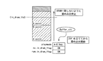
また、本実施の形態では、区間再生中に再生を停止し、電源遮断しても区間再生状態を保持することができる。区間開始地点、終了地点、バッファ内再生モード情報(フラグ)再生停止したときのバッファ内の再生カウンタを不揮発性メモリに記憶しておき、電源投入後に状態を復帰させる。図13(a)、(b)、(c)には、電源遮断後スリープから復帰したときの状態を示す。スリープ前には(a)のようにバッファ内区間再生を行っており、このときフラグはnv.in_dram_flgと、ram.in_dram_flagともonになっている。また、リジューム地点を保存している。スリープから復帰直後、(b)に示すように通常再生繰り返しになる。リジューム地点からため込みを行うが、B地点でプレイモードが異なることを判断すると、再生を停止する。その後、A地点から再ため込みを行う。そして、再ため込み終了後、(c)に示すように、A−B区間をリピート再生する。 Further, in the present embodiment, playback is stopped during section playback, and the section playback state can be maintained even if the power is cut off. The section start point, end point, and in-buffer playback mode information (flag), the playback counter in the buffer when playback is stopped are stored in the nonvolatile memory, and the state is restored after the power is turned on. FIGS. 13A, 13B, and 13C show states when returning from sleep after power-off. Before sleep, the in-buffer section playback is performed as shown in (a). At this time, both the nv.in_dram_flg and ram.in_dram_flag flags are on. In addition, the resume point is saved. Immediately after returning from sleep, normal reproduction is repeated as shown in FIG. Although accumulation is performed from the resume point, when it is determined that the play mode is different at the B point, the reproduction is stopped. Thereafter, re-storing is performed from point A. Then, after re-storing is completed, as shown in (c), the AB section is repeatedly reproduced.
なお、図6のステップS25にて再生を一時停止し、ステップS26にて再生カウンタをバッファ内の開始地点に設定する処理は以下に示す状態変化をトリガにしてもよい。メモリコントローラ15は、繰り返し再生の終了地点の記録データが溜め込まれているDRAM12内の溜め込み終了位置から繰り返し再生の開始地点Aの記録データを溜め込み開始位置の手前まで溜め込む。
Note that the process of pausing playback at step S25 in FIG. 6 and setting the playback counter at the start point in the buffer at step S26 may be triggered by the following state change. The
これにより、システムコントローラ16は、DRAM12内の溜め込み終了位置に溜め込まれている繰り返し再生の終了地点Bと、溜め込み開始位置の手前まで溜め込まれている上記繰り返し再生の開始地点Aからの記録データとの切り替わりを検出することにより、DRAM12内の溜め込み開始位置に飛んで繰り返し再生の開始地点から再生を行う。
As a result, the
また、終了地点Bになったら、そのままB以降のデータをDRAM12に続けてため込んでもよい。この場合には、繰り返し再生区間が解除されたときには、ディスクを回し、サーボを動作させ、光ピックアップを動かしというメカ的な遅延が発生しても、時間的な余裕を稼ぐことができる。
Further, when the end point B is reached, the data after B may be stored in the
1 光磁気ディスク再生装置、2 光磁気ディスク、3 ディスク読み出し部、12 DRAM、15 メモリコントローラ
1 magneto-optical disk playback device, 2 magneto-optical disk, 3 disk reading unit, 12 DRAM, 15 memory controller
Claims (7)
上記読み出し手段により読み出された記録データが溜め込まれる記憶手段と、
上記記録データからなる一つのトラック内で繰り返し再生の開始地点と終了地点とで特定される区間が指定されると、当該指定繰り返し再生区間の時間的長さと、上記記憶手段の所定記憶容量分の時間的長さとを比較し、比較結果に基づいて上記記憶手段内に一度溜め込まれた記録データのみで繰り返し再生処理が行われる記憶手段内繰り返し再生処理を実行する記憶制御手段とを備え、
上記記憶制御手段は、上記記憶手段内繰り返し再生処理を実行するときには、上記記憶手段内繰り返し再生処理を行うことを示すフラグをオンにしてから上記記憶手段内に記録データを溜め込むとともに、電源遮断前に上記繰り返し再生の開始地点と上記繰り返し再生の終了地点と上記フラグと上記記憶手段内繰り返し再生処理を停止したときの上記記憶手段内の再生カウンタとを不揮発性メモリに記憶し、
上記記憶手段内繰り返し再生処理中に再生を停止し、電源遮断後、電源投入されたときには、上記不揮発性メモリに記憶した繰り返し再生の開始地点と繰り返し再生の終了地点と上記フラグと上記記憶手段内繰り返し再生処理を停止したときの上記記憶手段内の再生カウンタとに基づいて、再び停止した位置から再生を開始して上記指定繰り返し再生区間での上記記憶手段内繰り返し再生処理に戻る再生装置。 A reading means for reading the recorded data recorded on the disk-shaped recording medium;
Storage means for storing recording data read by the reading means;
When a section specified by the start point and end point of repeated playback is specified in one track composed of the recording data, the time length of the specified repeated playback section and a predetermined storage capacity of the storage means A storage control means for performing a repeated reproduction process in the storage means for comparing the time length and performing the repeated reproduction process only with the recording data once stored in the storage means based on the comparison result ,
The storage control means, when executing the repetitive reproduction process in the storage means, turns on a flag indicating that the repetitive reproduction process in the storage means is turned on and then stores the recording data in the storage means, and before turning off the power. Storing the start point of the repeated playback, the end point of the repeated playback, the flag, and the playback counter in the storage unit when the repeated playback process in the storage unit is stopped in a nonvolatile memory,
When the playback is stopped during the repeated playback process in the storage means and the power is turned on after the power is turned off, the repeated playback start point, the repeated playback end point, the flag, and the storage means stored in the nonvolatile memory are stored. based on the reproduction counter in the memory when stopping the repeated reproduction process, playback device returns from the stop position in the storage means in repetitive reproduction process at the specified repetition reproduction section to start playback.
Priority Applications (1)
| Application Number | Priority Date | Filing Date | Title |
|---|---|---|---|
| JP2004134326A JP4301069B2 (en) | 2004-04-28 | 2004-04-28 | Playback device |
Applications Claiming Priority (1)
| Application Number | Priority Date | Filing Date | Title |
|---|---|---|---|
| JP2004134326A JP4301069B2 (en) | 2004-04-28 | 2004-04-28 | Playback device |
Publications (3)
| Publication Number | Publication Date |
|---|---|
| JP2005317122A JP2005317122A (en) | 2005-11-10 |
| JP2005317122A5 JP2005317122A5 (en) | 2007-06-14 |
| JP4301069B2 true JP4301069B2 (en) | 2009-07-22 |
Family
ID=35444375
Family Applications (1)
| Application Number | Title | Priority Date | Filing Date |
|---|---|---|---|
| JP2004134326A Expired - Fee Related JP4301069B2 (en) | 2004-04-28 | 2004-04-28 | Playback device |
Country Status (1)
| Country | Link |
|---|---|
| JP (1) | JP4301069B2 (en) |
Families Citing this family (3)
| Publication number | Priority date | Publication date | Assignee | Title |
|---|---|---|---|---|
| WO2007102388A1 (en) * | 2006-03-01 | 2007-09-13 | Pioneer Corporation | Information reproduction device and method and computer program |
| JP2013258637A (en) * | 2012-06-14 | 2013-12-26 | Toshiba Alpine Automotive Technology Corp | Reproducer |
| JP7025626B2 (en) * | 2017-07-12 | 2022-02-25 | 株式会社バッファロー | The hard disk memory system and its management method, the program that realizes the hard disk memory system in the computer, and the medium on which the program is recorded. |
-
2004
- 2004-04-28 JP JP2004134326A patent/JP4301069B2/en not_active Expired - Fee Related
Also Published As
| Publication number | Publication date |
|---|---|
| JP2005317122A (en) | 2005-11-10 |
Similar Documents
| Publication | Publication Date | Title |
|---|---|---|
| JP3199082B2 (en) | Audio data break position adjustment method and apparatus | |
| US6785213B2 (en) | Disk drive apparatus, and disk formatting method | |
| US5650991A (en) | Magneto-optical disc having preformatted information to prevent unauthorized data duplication | |
| JP3431030B2 (en) | Reproduction device and reproduction method | |
| JP4301069B2 (en) | Playback device | |
| JPH0644687A (en) | Disk recorder | |
| JP4000425B2 (en) | Data reproducing apparatus and data reproducing method | |
| JP3361186B2 (en) | Optical record carrier playback device | |
| JP3209369B2 (en) | Recording and playback device | |
| JP3869638B2 (en) | Disc recording device and disc | |
| JP2002140858A (en) | Control method of reproducing device | |
| JP4403388B2 (en) | Playback device | |
| JP4315052B2 (en) | Disc-shaped recording medium playback device | |
| JP4264651B2 (en) | Playback device and playback method | |
| JP3749039B2 (en) | Information reproducing apparatus and information recording apparatus | |
| JP3348723B2 (en) | Prepaid recording media | |
| JP3433829B2 (en) | Information reproducing apparatus and high-speed reproducing method | |
| JP3518744B2 (en) | Reproduction apparatus and reproduction method | |
| JP2005182970A (en) | Recording/reproducing device, and buffer memory management method | |
| JP3559930B2 (en) | Information playback device | |
| JP4403784B2 (en) | Recording / reproducing apparatus and recording / reproducing method | |
| JP2000268494A (en) | Recorder | |
| JPH04339382A (en) | Reproducing device for on-vehicle recording carrier | |
| JPH06203538A (en) | Storage device | |
| JP2005182858A (en) | Recording/reproducing device, and reproducing method |
Legal Events
| Date | Code | Title | Description |
|---|---|---|---|
| A521 | Written amendment |
Free format text: JAPANESE INTERMEDIATE CODE: A523 Effective date: 20070423 |
|
| A621 | Written request for application examination |
Free format text: JAPANESE INTERMEDIATE CODE: A621 Effective date: 20070423 |
|
| A977 | Report on retrieval |
Free format text: JAPANESE INTERMEDIATE CODE: A971007 Effective date: 20081215 |
|
| A131 | Notification of reasons for refusal |
Free format text: JAPANESE INTERMEDIATE CODE: A131 Effective date: 20090120 |
|
| A521 | Written amendment |
Free format text: JAPANESE INTERMEDIATE CODE: A523 Effective date: 20090312 |
|
| TRDD | Decision of grant or rejection written | ||
| A01 | Written decision to grant a patent or to grant a registration (utility model) |
Free format text: JAPANESE INTERMEDIATE CODE: A01 Effective date: 20090331 |
|
| A01 | Written decision to grant a patent or to grant a registration (utility model) |
Free format text: JAPANESE INTERMEDIATE CODE: A01 |
|
| FPAY | Renewal fee payment (event date is renewal date of database) |
Free format text: PAYMENT UNTIL: 20120501 Year of fee payment: 3 |
|
| A61 | First payment of annual fees (during grant procedure) |
Free format text: JAPANESE INTERMEDIATE CODE: A61 Effective date: 20090413 |
|
| FPAY | Renewal fee payment (event date is renewal date of database) |
Free format text: PAYMENT UNTIL: 20120501 Year of fee payment: 3 |
|
| FPAY | Renewal fee payment (event date is renewal date of database) |
Free format text: PAYMENT UNTIL: 20120501 Year of fee payment: 3 |
|
| FPAY | Renewal fee payment (event date is renewal date of database) |
Free format text: PAYMENT UNTIL: 20130501 Year of fee payment: 4 |
|
| LAPS | Cancellation because of no payment of annual fees |