JP4300977B2 - Barrier plastic container - Google Patents
Barrier plastic container Download PDFInfo
- Publication number
- JP4300977B2 JP4300977B2 JP2003368512A JP2003368512A JP4300977B2 JP 4300977 B2 JP4300977 B2 JP 4300977B2 JP 2003368512 A JP2003368512 A JP 2003368512A JP 2003368512 A JP2003368512 A JP 2003368512A JP 4300977 B2 JP4300977 B2 JP 4300977B2
- Authority
- JP
- Japan
- Prior art keywords
- plastic container
- barrier
- layer
- container
- plastic
- Prior art date
- Legal status (The legal status is an assumption and is not a legal conclusion. Google has not performed a legal analysis and makes no representation as to the accuracy of the status listed.)
- Expired - Fee Related
Links
- 239000004033 plastic Substances 0.000 title claims description 69
- 229920003023 plastic Polymers 0.000 title claims description 69
- 230000004888 barrier function Effects 0.000 title claims description 62
- VYPSYNLAJGMNEJ-UHFFFAOYSA-N Silicium dioxide Chemical compound O=[Si]=O VYPSYNLAJGMNEJ-UHFFFAOYSA-N 0.000 claims description 17
- 229910052814 silicon oxide Inorganic materials 0.000 claims description 17
- OKTJSMMVPCPJKN-UHFFFAOYSA-N Carbon Chemical group [C] OKTJSMMVPCPJKN-UHFFFAOYSA-N 0.000 claims description 14
- 229910052799 carbon Inorganic materials 0.000 claims description 13
- 239000001257 hydrogen Substances 0.000 claims description 12
- 229910052739 hydrogen Inorganic materials 0.000 claims description 12
- 239000000463 material Substances 0.000 claims description 12
- UFHFLCQGNIYNRP-UHFFFAOYSA-N Hydrogen Chemical compound [H][H] UFHFLCQGNIYNRP-UHFFFAOYSA-N 0.000 claims description 10
- 238000002834 transmittance Methods 0.000 claims description 10
- 239000000203 mixture Substances 0.000 claims description 8
- 239000007789 gas Substances 0.000 description 17
- 238000000034 method Methods 0.000 description 14
- QVGXLLKOCUKJST-UHFFFAOYSA-N atomic oxygen Chemical compound [O] QVGXLLKOCUKJST-UHFFFAOYSA-N 0.000 description 13
- 239000001301 oxygen Substances 0.000 description 13
- 229910052760 oxygen Inorganic materials 0.000 description 13
- 239000010408 film Substances 0.000 description 10
- XLYOFNOQVPJJNP-UHFFFAOYSA-N water Chemical compound O XLYOFNOQVPJJNP-UHFFFAOYSA-N 0.000 description 10
- 239000000758 substrate Substances 0.000 description 7
- 239000010409 thin film Substances 0.000 description 6
- -1 polyethylene Polymers 0.000 description 5
- 229920000139 polyethylene terephthalate Polymers 0.000 description 5
- 239000005020 polyethylene terephthalate Substances 0.000 description 5
- 230000015572 biosynthetic process Effects 0.000 description 4
- HSFWRNGVRCDJHI-UHFFFAOYSA-N alpha-acetylene Natural products C#C HSFWRNGVRCDJHI-UHFFFAOYSA-N 0.000 description 3
- 239000004035 construction material Substances 0.000 description 3
- 125000002534 ethynyl group Chemical group [H]C#C* 0.000 description 3
- 238000000465 moulding Methods 0.000 description 3
- 230000035699 permeability Effects 0.000 description 3
- 238000000623 plasma-assisted chemical vapour deposition Methods 0.000 description 3
- IKHGUXGNUITLKF-UHFFFAOYSA-N Acetaldehyde Chemical compound CC=O IKHGUXGNUITLKF-UHFFFAOYSA-N 0.000 description 2
- 239000004215 Carbon black (E152) Substances 0.000 description 2
- ATUOYWHBWRKTHZ-UHFFFAOYSA-N Propane Chemical compound CCC ATUOYWHBWRKTHZ-UHFFFAOYSA-N 0.000 description 2
- UBAZGMLMVVQSCD-UHFFFAOYSA-N carbon dioxide;molecular oxygen Chemical compound O=O.O=C=O UBAZGMLMVVQSCD-UHFFFAOYSA-N 0.000 description 2
- 239000000919 ceramic Substances 0.000 description 2
- UQEAIHBTYFGYIE-UHFFFAOYSA-N hexamethyldisiloxane Chemical compound C[Si](C)(C)O[Si](C)(C)C UQEAIHBTYFGYIE-UHFFFAOYSA-N 0.000 description 2
- 229930195733 hydrocarbon Natural products 0.000 description 2
- 150000002430 hydrocarbons Chemical class 0.000 description 2
- 150000002431 hydrogen Chemical class 0.000 description 2
- VNWKTOKETHGBQD-UHFFFAOYSA-N methane Chemical compound C VNWKTOKETHGBQD-UHFFFAOYSA-N 0.000 description 2
- 239000000178 monomer Substances 0.000 description 2
- 150000003961 organosilicon compounds Chemical class 0.000 description 2
- OTMSDBZUPAUEDD-UHFFFAOYSA-N Ethane Chemical compound CC OTMSDBZUPAUEDD-UHFFFAOYSA-N 0.000 description 1
- 239000004698 Polyethylene Substances 0.000 description 1
- 239000004642 Polyimide Substances 0.000 description 1
- 239000004743 Polypropylene Substances 0.000 description 1
- BOTDANWDWHJENH-UHFFFAOYSA-N Tetraethyl orthosilicate Chemical compound CCO[Si](OCC)(OCC)OCC BOTDANWDWHJENH-UHFFFAOYSA-N 0.000 description 1
- 238000000071 blow moulding Methods 0.000 description 1
- 229910002090 carbon oxide Inorganic materials 0.000 description 1
- 239000011248 coating agent Substances 0.000 description 1
- 238000000576 coating method Methods 0.000 description 1
- 230000007423 decrease Effects 0.000 description 1
- 238000010828 elution Methods 0.000 description 1
- 238000001125 extrusion Methods 0.000 description 1
- 238000001746 injection moulding Methods 0.000 description 1
- 238000003475 lamination Methods 0.000 description 1
- 238000004519 manufacturing process Methods 0.000 description 1
- 150000002894 organic compounds Chemical class 0.000 description 1
- 238000004806 packaging method and process Methods 0.000 description 1
- 239000012466 permeate Substances 0.000 description 1
- 238000005268 plasma chemical vapour deposition Methods 0.000 description 1
- 229920000573 polyethylene Polymers 0.000 description 1
- 229920001721 polyimide Polymers 0.000 description 1
- 229920001155 polypropylene Polymers 0.000 description 1
- 239000001294 propane Substances 0.000 description 1
- UHUUYVZLXJHWDV-UHFFFAOYSA-N trimethyl(methylsilyloxy)silane Chemical compound C[SiH2]O[Si](C)(C)C UHUUYVZLXJHWDV-UHFFFAOYSA-N 0.000 description 1
Images

Description
本発明は、バリア性と透明性に優れるプラスチック容器、特に水分を含む内容物やその水分が容器の内表面に接触したり、付着しても当初のバリア性が低下しないようにしたことを特徴とするバリア性プラスチック容器に関するものである。 The present invention is characterized in that a plastic container excellent in barrier properties and transparency, in particular, contents containing moisture and the moisture does not deteriorate even if the moisture contacts or adheres to the inner surface of the container. It relates to a barrier plastic container.
ここ最近、プラスチック容器は、その成形の容易性や軽量性、さらには低コスト性等の様々な特性から、食品分野や医薬品分野等の様々な分野において、包装容器として広く使用されている。しかしながら、プラスチック容器は、酸素や二酸化炭素、水蒸気のような低分子ガスを透過する性質や、低分子有機化合物が内部に付着してしまうという性質、アセトアルデヒドの様な溶出成分があるという性質等を有しており、容器として改良しなければならない点が多々あった。 Recently, plastic containers are widely used as packaging containers in various fields such as the food field and the pharmaceutical field because of their various characteristics such as easy molding, light weight, and low cost. However, plastic containers have properties such as the permeation of low molecular gases such as oxygen, carbon dioxide, and water vapor, the property that low molecular organic compounds adhere to the inside, and the property that there are elution components such as acetaldehyde. There were many points that had to be improved as a container.
これらの諸問題を解決するためにいろいろな方策がとられているが、どれもが様々な問題を抱えており、前記諸問題を完全に解決することが出来ていない。例えば、プラスチック容器のガス透過性を低減する方法の1つとして、複数のプラスチック材料を使用して積層構成の容器としたり、種々のプラスチック材料がブレンドされたプラスチック材料により容器を作製する方法等がある。しかし、これらの方法を用いると、ある程度まではガス透過性を低減することは出来るが、より高いバリア性を求める容器が満足するレベルまでにはガス透過性を低減することができていない。また、上記方法で使用するプラスチック材料のコストも非常に高いものである。 Various measures have been taken to solve these problems, but all have various problems, and the above problems cannot be solved completely. For example, as one of the methods for reducing the gas permeability of a plastic container, there are a method of forming a container having a laminated structure using a plurality of plastic materials, a method of manufacturing a container using a plastic material in which various plastic materials are blended, and the like. is there. However, when these methods are used, the gas permeability can be reduced to a certain extent, but the gas permeability cannot be reduced to a level that satisfies a container that requires a higher barrier property. In addition, the cost of the plastic material used in the above method is very high.
一方、近年はプラスチック容器にセラミックの薄膜をプラズマCVD法等の真空プロセスを用いてコーティングする技術が様々開発されており、これらの技術によりセラミックの薄膜が形成されたプラスチック容器が広く出回っている。これらのほとんどは、単一のプラスチック材料からなるプラスチック成形品の表面にセラミックの薄膜を成膜し、バリア性を向上させているものであり、バリア性に優れた容器を安価に得ることができる(例えば、特許文献1参照。)。しかし、これらのプラスチック容器は、薄膜を形成した面が水分または水分を含有する内容物に直接触れるとその薄膜が劣化して当初のバリア性が低下してしまうといった問題点を抱えていた。 On the other hand, in recent years, various techniques for coating a plastic thin film on a plastic container using a vacuum process such as a plasma CVD method have been developed, and plastic containers in which a ceramic thin film is formed by these techniques are widely available. Most of these are made by forming a ceramic thin film on the surface of a plastic molded article made of a single plastic material to improve the barrier property, and a container having an excellent barrier property can be obtained at low cost. (For example, refer to Patent Document 1). However, these plastic containers have a problem that when the surface on which the thin film is formed directly touches moisture or the contents containing moisture, the thin film deteriorates and the initial barrier property is lowered.
本発明は上記従来技術の問題点を解決するためになされたもので、プラスチック容器の酸素や二酸化炭素、水蒸気のような低分子ガスを透過するという性質を、プラスチック容器の骨格を構成するプラスチック容器基体の表面に所定の薄膜を形成することで確実に低減させ、かつ、内部に収納した水や水分を含有する内容物が容器内面に直接接触させたとしても当初のバリア性が低下せず、かつ透明度も高いバリア性プラスチック容器の提供を課題とする。 The present invention has been made to solve the above-mentioned problems of the prior art, and the plastic container that constitutes the skeleton of the plastic container has the property that the plastic container is permeable to low molecular gases such as oxygen, carbon dioxide, and water vapor. Even if the content containing water or moisture stored inside is directly brought into contact with the inner surface of the container, the initial barrier property is not lowered, by forming a predetermined thin film on the surface of the substrate, and An object is to provide a barrier plastic container having high transparency.
このような課題を達成するためになされ、請求項1記載の発明は、プラスチック材料からなり、容器の形状に成形されているプラスチック容器基体の内表面に、層厚が0.2nm以上20nm以下で、炭素および水素の組成を共に40%以上で55%以下としたアンダーコート層と、層厚が10nm以上200nm以下で珪素酸化物からなるバリア層とがこの順序で積層されていると共に、前記両層の積層部分の全光線透過率が80%以上であることを特徴とするバリア性プラスチック容器である。
本発明のバリア性プラスチック容器は、バリア性と透明性に優れ、しかも水や水分を含有する内容物が容器の内表面に直接接触したとしても当初のバリア性が低下しない。 The barrier plastic container of the present invention is excellent in barrier properties and transparency, and even if the content containing water or moisture is in direct contact with the inner surface of the container, the initial barrier property does not deteriorate.
以下、本発明を図面を参照にして詳細に説明する。 Hereinafter, the present invention will be described in detail with reference to the drawings.
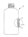
図1は、本発明のバリア性プラスチック容器の一実施形態を示す一部断面構成説明図である。このバリア性プラスチック容器1は、その骨格を構成するプラスチック容器基体2の内表面に、層厚が0.2nm以上で20nm以下、炭素および水素の組成を共に40%以上で55%以下としたアンダーコート層3と、珪素酸化物からなり、層厚が10nm以上で200nm以下のバリア層4とがこの順序で積層されている。また、上記各層の積層部分における全光線透過率は80%以上となっている。
FIG. 1 is a partial cross-sectional configuration explanatory view showing an embodiment of the barrier plastic container of the present invention. Under this barrier
一方、図2には従来のバリア性プラスチック容器11の一例が示してある。このバリア性プラスチック容器11は、その骨格を構成するプラスチック容器基体12の内表面側に珪素酸化物層14が積層して設けられていて、所期のバリア性が付与されている。しかし、このように珪素酸化物層14のみがプラスチック容器基体12の内表面に積層されているバリア性プラスチック容器11の場合は、例えば水分を含有する内容物がこの珪素酸化物層14に直接触れると、水分が珪素酸化物層に移行、浸透し、プラスチック容器基体12と珪素酸化物層15との界面が劣化し、当初のバリア性が低下するといった問題点があった。
On the other hand, FIG. 2 shows an example of a conventional barrier
しかし、本発明のバリア性プラスチック容器のように、バリア層とプラスチック容器基体との間に炭素および水素の組成を共に40%以上で55%以下としたアンダーコート層を介在させ、しかも各層の層厚を上述のような範囲内に設定すると、バリア層とプラスチック容器基体との密着性が向上し、界面の劣化を防ぐことができるようになるため、例え水分を含有する内容物がその内層に直接触れたとしても、初期のバリア性を維持し続けることができる。 However, as in the barrier plastic container of the present invention, an undercoat layer in which the composition of carbon and hydrogen is both 40% and 55% is interposed between the barrier layer and the plastic container substrate, and the layers of each layer When the thickness is set within the above range, the adhesion between the barrier layer and the plastic container substrate is improved and the interface can be prevented from being deteriorated. For example, the content containing moisture is contained in the inner layer. Even if touched directly, the initial barrier property can be maintained.
前記したプラスチック容器基体2はポリエチレン、ポリプロピレン、ポリエチレンテレフタレート、ポリイミド等のプラスチック材料からなり、これらのプラスチック材料をブロー成形、射出成形、押出成形等の成形方法により容器の形状に成形して得られるものである。
The
また、柔軟性のより高いアンダーコート層3を形成するためには、炭素および水素を主成分とする構成材料にて構成し、その炭素および水素の組成を共に40%以上で55%以下とする。
Further, in order to form a
このような炭素および水素の組成を共に40%以上で55%以下としたアンダーコート層3の形成方法としては、3次元形態に成形されたプラスチック容器基体2の内表面に、均一で、しかも低コストで薄層を形成できることから、アセチレン、メタン、エタン、プロパン等の炭化水素ガスを使用したプラズマ助成式CVD法を用いることが望まれる。
As a method of forming the
また、珪素酸化物からなるバリア層4の形成方法としても、同様の理由から、ヘキサメチルジシロキサン、テトラメチルジシロキサン、テトラエトキシシラン等の有機珪素化合物モノマーガスを使用したプラスマ助成式CVD法を用いることが望ましい。
Also, as a method for forming the
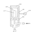
プラズマ助成式CVD法を用いてプラスチック容器基体2の内表面に炭素を主成分としてなるアンダーコート層3、珪素酸化物からなるバリア層4を順次に積層させるためには、例えば図3に示すような成膜装置を使用し、次のようにして成膜を行う。
In order to sequentially deposit the
成膜に当たっては、まず、装置のチャンバー内を真空引きした後、そこに炭化水素ガスを導入する。次に、高周波電源24から外部電極25に高周波電力を印加して外部電極25と内部電極27の間にプラズマを発生させ、さらに高周波電力を印加し続けたまま、今度は有機珪素化合物モノマーガスを導入してプラズマを発生させ、プラスチック容器基体の内表面に、層厚が0.2nm以上20nm以下で、炭素および水素の組成を共に40%以上で55%以下としたアンダーコート層3と珪素酸化物からなるバリア層4を順次積層して形成する。
In film formation, first, the inside of the chamber of the apparatus is evacuated and then a hydrocarbon gas is introduced therein. Next, high frequency power is applied from the high
炭素および水素の組成を共に40%以上で55%以下としたアンダーコート層3は着色
する場合が多く、高い光透過性の発現を考慮して層厚を薄くする必要がある。この層厚は、容器の使用目的等にもよるが、前述したように、0.2nm以上で20nm以上の範囲とする。また、珪素酸化物からなるバリア層4の層厚は、10nm以下では酸素や水蒸気等のバリア性が低下し、200nm以上ではクラックが形成されるため、10nm以上で200nm以下の範囲に設定する。そして、アンダーコート層3とバリア層4との積層部分の全光線透過率を80%以上とする。
The
以下、本発明のバリア性プラスチック容器を具体的な実施例を挙げてさらに説明する。 Hereinafter, the barrier plastic container of the present invention will be further described with specific examples.
主要部構成が図3に示すような成膜装置を用い、下記のようにして、容量が500mlのポリエチレンテレフタレート(PET)製容器基体の内表面に炭素を主成分としてなるアンダーコート層と珪素酸化物からなるバリア層とを順次に成膜した。 Using a film forming apparatus whose main part configuration is shown in FIG. 3, an undercoat layer mainly composed of carbon and silicon oxide on the inner surface of a polyethylene terephthalate (PET) container base having a capacity of 500 ml as follows: A barrier layer made of a material was sequentially formed.
まず、アセチレンをガス流量を10cc/minにしてガス導入管を通して成膜装置のチャンバー内にセットしてあるPET製容器基体内に導入した後、成膜時圧力は0.5torr、印加する高周波電力は250wattとして成膜を行った。さらに250wattの高周波電力を印加したまま前記工程に引き続き、今度はヘキサメチルジシロキサンと酸素の混合ガスをガス流量を500cc/minにしてガス導入管を通して前記PET製容器基体内に導入し、引き続き容器の内表面に成膜を行い、実施例1に係る本発明のバリア性プラスチック容器を得た。このとき、第1層目の炭素および水素を主成分とする構成材料にて構成されるアンダーコート層の層厚は2nmであり、第2層目の珪素酸化物からなるバリア層の層厚は50nmであった。 First, after introducing acetylene into a PET container substrate set in the chamber of the film forming apparatus through a gas introduction pipe with a gas flow rate of 10 cc / min, the pressure during film formation is 0.5 torr, and the high frequency power to be applied. Was deposited at 250 watts. Further, following the above process while applying 250 watts of high-frequency power, this time, a mixed gas of hexamethyldisiloxane and oxygen was introduced into the PET container substrate through the gas introduction pipe at a gas flow rate of 500 cc / min. A film was formed on the inner surface of the container, and the barrier plastic container of the present invention according to Example 1 was obtained. At this time, the layer thickness of the undercoat layer that consists in construction material composed mainly of carbon and hydrogen of the first layer is 2 nm, the layer thickness of the barrier layer of a second layer of silicon oxide It was 50 nm.
得られたバリア性プラスチック容器の、MOCON社製OXTRANにより測定した酸素バリア性のデータ、および日本電飾工業社製のHaze Meter NDH2000により測定した全光線透過率データを表1に示す。また、得られたバリア性プラスチック容器に水を充填して40℃で30日間保存した後のバリア性プラスチック容器のMOCON社製OXTRANにより測定した酸素バリア性のデータも同様に表1に示す。 Table 1 shows the oxygen barrier property data measured by OXTRAN manufactured by MOCON, and the total light transmittance data measured by Haze Meter NDH2000 manufactured by Nippon Denka Kogyo Co., Ltd. for the obtained barrier plastic container. Table 1 also shows oxygen barrier property data measured by OXTRAN manufactured by MOCON of the barrier plastic container after the obtained barrier plastic container was filled with water and stored at 40 ° C. for 30 days.
バリア性プラスチック容器の一部を構成する、炭素および水素を主成分とする構成材料にて構成されるアンダーコート層の層厚が10nmであったこと以外は実施例1と同様の条件で成膜を行い、実施例2に係る本発明のバリア性プラスチック容器を得た。 Constituting a part of a barrier plastic container, formed under the same conditions as in Example 1 except that the layer thickness of the undercoat layer that consists in construction material composed mainly of carbon and hydrogen content of 10nm The barrier plastic container of the present invention according to Example 2 was obtained.
得られたバリア性プラスチック容器の、MOCON社製OXTRANにより測定した酸素バリア性のデータ、および日本電飾工業社製のHaze Meter NDH2000により測定した全光線透過率データを表1に示す。また、得られたバリア性プラスチック容器に水を充填して40℃で30日間保存した後のバリア性プラスチック容器のMOCON社製OXTRANにより測定した酸素バリア性のデータも同様に表1に示す。 Table 1 shows the oxygen barrier property data measured by OXTRAN manufactured by MOCON, and the total light transmittance data measured by Haze Meter NDH2000 manufactured by Nippon Denka Kogyo Co., Ltd. for the obtained barrier plastic container. Table 1 also shows oxygen barrier property data measured by OXTRAN manufactured by MOCON of the barrier plastic container after the obtained barrier plastic container was filled with water and stored at 40 ° C. for 30 days.
炭素および水素を主成分とする構成材料にて構成されるアンダーコート層の層厚が40nmであったこと以外は実施例1と同様の条件で成膜を行い、実施例3に係る比較のためのプラスチック容器を得た。 Perform film formation under the same conditions as in Example 1 except that the layer thickness of the undercoat layer that consists in construction material composed mainly of carbon and hydrogen content of 40 nm, for comparison according to Example 3 A plastic container was obtained.
得られたプラスチック容器の、MOCON社製OXTRANにより測定した酸素バリア性のデータ、および日本電飾工業社製のHaze Meter NDH2000により測定した全光線透過率データを表1に示す。また、得られたプラスチック容器に水を充填して40℃で30日間保存した後のプラスチック容器のMOCON社製OXTRANにより測定した酸素バリア性のデータも同様に表1に示す。 Table 1 shows the oxygen barrier property data measured by OXTRAN manufactured by MOCON and the total light transmittance data measured by Haze Meter NDH2000 manufactured by Nippon Denshoku Kogyo Co., Ltd. Table 1 also shows the oxygen barrier property data measured by OXTRAN manufactured by MOCON of the plastic container after the obtained plastic container was filled with water and stored at 40 ° C. for 30 days.
原料ガスにアセチレンは用いずに、ヘキサメチルジシロキサンと酸素の混合ガスのみを用いたこと以外は実施例1と同様の条件で成膜を行い、実施例4に係る比較のためのプラスチック容器を得た。このときの珪素酸化物からなるバリア層の層厚は50nmであった。 A film was formed under the same conditions as in Example 1 except that only hexylenedisiloxane and oxygen mixed gas was used instead of acetylene as a source gas, and a plastic container for comparison according to Example 4 was prepared. Obtained. At this time, the thickness of the barrier layer made of silicon oxide was 50 nm.
得られたプラスチック容器の、MOCON社製OXTRANにより測定した酸素バリア性のデータ、および日本電飾工業社製のHaze Meter NDH2000により測定した全光線透過率データを表1に示す。また、得られたプラスチック容器に水を充填して40℃で30日間保存した後のプラスチック容器のMOCON社製OXTRANにより測定した酸素バリア性のデータも同様に表1に示す。 Table 1 shows the oxygen barrier property data measured by OXTRAN manufactured by MOCON and the total light transmittance data measured by Haze Meter NDH2000 manufactured by Nippon Denshoku Kogyo Co., Ltd. Table 1 also shows the oxygen barrier property data measured by OXTRAN manufactured by MOCON of the plastic container after the obtained plastic container was filled with water and stored at 40 ° C. for 30 days.
珪素酸化物層の層厚が10nmであったこと以外は実施例1と同様の条件で成膜を行い、実施例5に係る比較のためのプラスチック容器を得た。 Film formation was performed under the same conditions as in Example 1 except that the thickness of the silicon oxide layer was 10 nm, and a plastic container for comparison according to Example 5 was obtained.
得られたプラスチック容器の、MOCON社製OXTRANにより測定した酸素バリア性のデータ、および日本電飾工業社製のHaze Meter NDH2000により測定した全光線透過率データを表1に示す。また、得られたプラスチック容器に水を充填して40℃で30日間保存した後のプラスチック容器のMOCON社製OXTRANにより測定した酸素バリア性のデータも同様に表1に示す。 Table 1 shows the oxygen barrier property data measured by OXTRAN manufactured by MOCON and the total light transmittance data measured by Haze Meter NDH2000 manufactured by Nippon Denshoku Kogyo Co., Ltd. Table 1 also shows the oxygen barrier property data measured by OXTRAN manufactured by MOCON of the plastic container after the obtained plastic container was filled with water and stored at 40 ° C. for 30 days.

1、11・・・バリア性プラスチック容器
2、12・・・プラスチック容器基体
3 ・・・アンダーコート層
4 ・・・バリア層
14 ・・・珪素酸化物層
24 ・・・高周波電源
25 ・・・外部電極
26 ・・・外部電極天蓋部
27 ・・・内部電極
28 ・・・絶縁板
29 ・・・ガス供給孔
DESCRIPTION OF
Claims (1)
Priority Applications (1)
| Application Number | Priority Date | Filing Date | Title |
|---|---|---|---|
| JP2003368512A JP4300977B2 (en) | 2003-10-29 | 2003-10-29 | Barrier plastic container |
Applications Claiming Priority (1)
| Application Number | Priority Date | Filing Date | Title |
|---|---|---|---|
| JP2003368512A JP4300977B2 (en) | 2003-10-29 | 2003-10-29 | Barrier plastic container |
Publications (2)
| Publication Number | Publication Date |
|---|---|
| JP2005132393A JP2005132393A (en) | 2005-05-26 |
| JP4300977B2 true JP4300977B2 (en) | 2009-07-22 |
Family
ID=34646154
Family Applications (1)
| Application Number | Title | Priority Date | Filing Date |
|---|---|---|---|
| JP2003368512A Expired - Fee Related JP4300977B2 (en) | 2003-10-29 | 2003-10-29 | Barrier plastic container |
Country Status (1)
| Country | Link |
|---|---|
| JP (1) | JP4300977B2 (en) |
Families Citing this family (2)
| Publication number | Priority date | Publication date | Assignee | Title |
|---|---|---|---|---|
| JP4899471B2 (en) * | 2005-12-26 | 2012-03-21 | 凸版印刷株式会社 | Gas barrier plastic container and manufacturing method thereof |
| JP2008094447A (en) * | 2006-10-13 | 2008-04-24 | Toppan Printing Co Ltd | Plastic container coated with thin film |
-
2003
- 2003-10-29 JP JP2003368512A patent/JP4300977B2/en not_active Expired - Fee Related
Also Published As
| Publication number | Publication date |
|---|---|
| JP2005132393A (en) | 2005-05-26 |
Similar Documents
| Publication | Publication Date | Title |
|---|---|---|
| JP4158265B2 (en) | Plastic container manufacturing method and container | |
| WO2004087989A1 (en) | Chemical vapor deposition film formed by plasma cvd process and method for forming same | |
| JP4936764B2 (en) | DLC film coated biodegradable plastic container or film and method for producing the same | |
| JPH08175528A (en) | Method for forming silicon oxide film of uniform film thickness on three-dimensional container made of plastic material | |
| BRPI0611779B1 (en) | POLYMER ARTICLE HAVING SLIM COATING OF PLASMA AT LEAST ONE OF ITS SIDES AND METHOD FOR PRODUCING SUCH ARTICLE | |
| KR20060132994A (en) | Synthetic resin container with high gas barrier performance | |
| JP4300977B2 (en) | Barrier plastic container | |
| JP2000079944A (en) | Plastic container and its manufacture | |
| JP5273760B2 (en) | Plastic container | |
| TW201226606A (en) | Gas-barrier laminate film | |
| JP2003104352A (en) | Plastic container with barrier properties | |
| JP2018020540A (en) | Barrier film | |
| WO2005092714A1 (en) | Synthetic resin container with high gas barrier performance | |
| JP4268545B2 (en) | Plastic container | |
| JP2004168325A (en) | Plastic container with barrier property | |
| JP4899471B2 (en) | Gas barrier plastic container and manufacturing method thereof | |
| JP6888455B2 (en) | Manufacturing method of gas barrier plastic container | |
| TWI577822B (en) | Multilayer hard coating film structure and method for producing the same | |
| JP4593213B2 (en) | Gas barrier plastic container and manufacturing method thereof | |
| JP4244667B2 (en) | Deposition method | |
| JP7005256B2 (en) | Gas barrier container | |
| JP2001301731A (en) | Plastic container | |
| JP2006082814A (en) | Plastic container of gas barrier property | |
| JP4333382B2 (en) | Gas barrier plastic container | |
| JPH1170611A (en) | Transparent gas barrier film |
Legal Events
| Date | Code | Title | Description |
|---|---|---|---|
| A621 | Written request for application examination |
Free format text: JAPANESE INTERMEDIATE CODE: A621 Effective date: 20060919 |
|
| A977 | Report on retrieval |
Free format text: JAPANESE INTERMEDIATE CODE: A971007 Effective date: 20081027 |
|
| A131 | Notification of reasons for refusal |
Free format text: JAPANESE INTERMEDIATE CODE: A131 Effective date: 20090106 |
|
| A521 | Request for written amendment filed |
Free format text: JAPANESE INTERMEDIATE CODE: A523 Effective date: 20090306 |
|
| TRDD | Decision of grant or rejection written | ||
| A01 | Written decision to grant a patent or to grant a registration (utility model) |
Free format text: JAPANESE INTERMEDIATE CODE: A01 Effective date: 20090331 |
|
| A01 | Written decision to grant a patent or to grant a registration (utility model) |
Free format text: JAPANESE INTERMEDIATE CODE: A01 |
|
| FPAY | Renewal fee payment (event date is renewal date of database) |
Free format text: PAYMENT UNTIL: 20120501 Year of fee payment: 3 |
|
| R150 | Certificate of patent or registration of utility model |
Ref document number: 4300977 Country of ref document: JP Free format text: JAPANESE INTERMEDIATE CODE: R150 Free format text: JAPANESE INTERMEDIATE CODE: R150 |
|
| A61 | First payment of annual fees (during grant procedure) |
Free format text: JAPANESE INTERMEDIATE CODE: A61 Effective date: 20090413 |
|
| FPAY | Renewal fee payment (event date is renewal date of database) |
Free format text: PAYMENT UNTIL: 20120501 Year of fee payment: 3 |
|
| FPAY | Renewal fee payment (event date is renewal date of database) |
Free format text: PAYMENT UNTIL: 20130501 Year of fee payment: 4 |
|
| FPAY | Renewal fee payment (event date is renewal date of database) |
Free format text: PAYMENT UNTIL: 20140501 Year of fee payment: 5 |
|
| LAPS | Cancellation because of no payment of annual fees |