JP4300447B2 - Coin hopper - Google Patents
Coin hopper Download PDFInfo
- Publication number
- JP4300447B2 JP4300447B2 JP2001009498A JP2001009498A JP4300447B2 JP 4300447 B2 JP4300447 B2 JP 4300447B2 JP 2001009498 A JP2001009498 A JP 2001009498A JP 2001009498 A JP2001009498 A JP 2001009498A JP 4300447 B2 JP4300447 B2 JP 4300447B2
- Authority
- JP
- Japan
- Prior art keywords
- coin
- passage
- lever
- detection
- hopper
- Prior art date
- Legal status (The legal status is an assumption and is not a legal conclusion. Google has not performed a legal analysis and makes no representation as to the accuracy of the status listed.)
- Expired - Fee Related
Links
Images


Description
【0001】
【発明が属する技術分野】
本発明は、コインを1個ずつ区分けして放出するコインホッパに関する。
なお、本明細書で使用する「コイン」は、通貨であるコインの他、ゲーム機のメダルやトークン等の代用貨幣または類似のものをも包含する。
【0002】
【従来の技術】
コインホッパは、例えば図6に図示するゲーム機に内蔵される。
101は内蔵されたコインホッパである。
102はコインの放出口である。
103はコイン投入口である。
コインホッパ101は、例えば米国特許第4589433号に開示のものと同様である。
【0003】
コインホッパ101の概要を、図7を参照して説明する。
水平配置されるベース110に固定されたフレーム111に約60度の角度で取り付けられたほぼ円板形のホッパベース112を有する。
ホッパベース112の裏面側にはモーター113が固定されている。
ホッパベース112の表面側にコイン送り出し装置Aを構成する回転ディスク114が配置されている。
【0004】
回転ディスク114は、前記モーター113から図示しない減速機を介して回転駆動される。
回転ディスク114の周縁部は段115を形成してリング状のコイン載置面116を形成してある。
コイン載置面116には所定間隔でピン117が固定してある。
118は回転ディスク114の外周を囲うようにホッパベース112に固定した円筒状のホッパリングである。
119はホッパリング118に開口端をあてがって取り付けたバケツ状のコインボウルである。
コインボウル119の上側側壁にコイン投入開口120が形成してある。
【0005】
121は受け取りナイフであって、基部をホッパベース112に固定してある。
ナイフ121の先端部は、段115に近接している。
130はコインカウンタであり、ホッパベース112に固定した固定軸131と、固定軸131に中間を揺動自在に取り付けたレバー132と、ナイフ121に相対してレバー132の先端部に取り付けたカウントローラ133と、レバー132の所定位置までの回動を検知するカウントセンサ(図示せず)とよりなっている。
前記ナイフ121の基部にはガイド板134が被せてある。
【0006】
レバー132は、図示しないスプリングにより反時計回り方向に回転力を付与されている。
ホッパベース112と、ガイド板134と、ナイフ121基部上面とでコイン通路135を構成している。
コイン通路135の端面がコイン出口136になっている。
【0007】
次にゲーム機100におけるコインの流れを説明する。
プレイヤーは、コイン投入口103にコインを投入してゲームを行う。
投入されたコインは、図示しないダクトにより案内されてコイン投入開口120からコインボウル119に入る。
プレイにより当選すると、ゲーム機100の制御回路(図示せず)はコインの払い出し信号を出力する。
【0008】
ゲーム機100の制御回路からコインの払い出し信号を受けるとコインホッパ101のモーター113が回転される。
モーター113の回転により回転ディスク114が図7において反時計回り方向に回転される。
回転ディスク114の回転により、コインボウル119内のコインは撹拌され、姿勢が変化する。
【0009】
前記姿勢変化によりコイン載置面116に側面が面接したコインは、ピン117に係止される。
係止されたコインは、段115により周面を支えられつつ回転ディスク114に連行される。
ナイフ121に到達するとコインは、ナイフ121によりすくい上げられる。
【0010】
この後コインは、ナイフ121の上縁に支えられつつピン117によりコイン通路135側に押し出される。
この途上でコインは、カウントローラ133を押し上げて通過する。
カウントローラ133の押し上げによりレバー132は時計回り方向に回転されるので、図示しないカウントセンサにより検知される。
カウントセンサは、放出コイン数「1」を意味するカウント信号を出力する。
【0011】
カウント信号を受けたゲーム機100の制御回路は、放出所定数になった場合、放出を終了するため、モーター113の回転を停止する。
カウントローラ133を通過したコインは、コイン通路135に押し出され、コイン出口136から放出される。
放出されたコインは、ダクトを通ってコイン払い出し口102に達する。
【0012】
最近、放出口102から手を挿入してコイン出口136を塞ぐことにより不正を行う者がいる。
すなわち、出口136がふさがれた場合、コイン通路135にコインが多数詰め込まれてコイン自身で栓をした状態になる。
【0013】
このため、モーター113は、過負荷になるので過電流が検出されて自動的に停止される。
あるいは、コインカウンタ130からカウント信号が所定時間発信されないので、ゲーム機100の制御回路が異常処理を行ってモーター113を停止する。不正者は、放出されるべきコイン数に満たないとしてクレームを付けることにより、余分にコインを入手する手口である。
【0014】
【発明が解決しようとする課題】
本発明は、コインホッパのコイン出口を塞がれたことを早期に確実に検知することにより、前記のような不正を防止することを目的とする。
詳しくは、コイン出口を塞がれたことを検知してその後に続くコインの供給を行わないようにすることを目的とする。
さらに詳しくは、コイン出口を塞がれたことを検知してその後に続くコインの供給を行わない簡単な機構を提供することを目的とする。
【0015】
【課題を解決するための手段】
この目的を達成するため本発明のコインホッパは、以下のように構成されている。前記送り出し装置(A)から送り出されたコインを出口(136)に向かって案内するコイン通路(B)と、前記コイン通路(B)に配置され、前記コイン通路に滞留する前記送り出されたコインによって所定位置に保持される検知体(C)と、前記検知体の位置に基づいて前記コイン通路に達する前に前記送り出し装置によって送り出されるコインを前記送り出し装置側へ方向転換させるコインの方向転換装置(D)を有するコインホッパである。
【0016】
この構成によれば、コイン通路が異常になった場合、検知体によって検知される。この検知に基づいてコインの方向転換装置がコインをコインの送り出し装置側へ方向転換させる。よって、その後に続くコインの供給を行わない。
【0017】
本発明は、前記検知体(C)がコイン通路(B)に突出するよう力を付与されたレバー(11)であることが好ましい。
この構成によれば、検知体(C)がレバー(11)であるため、直接コインにより移動されるので、摩耗粉などの影響を受けずにコインを検知できるので正確な検知ができる。
【0018】
また本発明は、前記方向転換装置(D)は、前記検知体(C)が所定時間を超えてコインを検知した場合、前記検知体(C)よりも上流のコイン搬送通路(E)に移動する方向転換体(23)を有することが好ましい。この構成によれば、検知体(C)がコインの所定時間以上の滞留を検知した場合、方向転換体(23)がコインの進行方向を転換してコイン通路(B)に供給されないようにしている。よって、コインが出口(136)に供給されないので、異常状態でのコインの放出数を極めて少なくできる。
【0019】
また本発明は、前記方向転換装置(D)は、前記レバー(11)に連動して検知体(C)の上流側のコイン通路(B)に突出するストッパ(11U)と、前記ストッパ(11U)の近傍の前記コイン通路(B)に連なる通路(B2)に配置した被動レバー(29)と、前記被動レバー(29)によりコイン搬送通路(E)に突出する方向転換体(23)と、を有することが好ましい。
この構成により、方向転換装置(D)が機械的な簡単な構成であるので安価に製作できる。
【0020】
【発明の実施の形態】
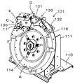
図1は実施例のコインボウルを外した状態の斜視図。
図2は実施例の正常状態の部分正面図。
図3は実施例の正常状態の部分斜視図。
図4は実施例のコイン通路の説明図(カバーを除去)。
図5は実施例の異常状態の説明図(カバーを除去)。
【0021】
従来技術と同一部には同一符号を付し、異なる構成を説明する。
図1は、コインボウル119を取り外した状態のコインホッパ101を右斜め上方から見た斜視図である。
コインの送り出し装置Aは、従来装置と同じく回転ディスク114とピン117で構成してある。
【0022】
次に図2、図3、図4を参照してコイン通路Bを説明する。
コイン通路Bは、ホッパベース112と、下側案内体2と、上側案内体3と、カバー4とにより、構成されている。
コイン通路Bは、左下がりに傾斜している。
【0023】
次に、下側案内体2の構造を説明する。
図3に示すように、平板状カバー4の下縁部を回転ディスク114及びホッパベース112側に直角に折り曲げて下側案内体2を形成している。
この折り曲げ量は、コインの厚みよりも僅かに大きい程度である。すなわち、コイン1枚の厚みよりも大きく、2枚の厚みよりも小さい。
【0024】
下側案内体2は、載置面116に相対する第1案内片2Xと、ホッパベース112に相対する誘導片2Yと、ホッパベース112に相対する検知案内片2Zとを有する。(図4では、便宜上一点鎖線にて図示)
第1案内片2Xは、第1分割案内片2X1と第2分割案内片2X2に分割されている。
第1分割案内片2X1と第2分割案内片2X2は、ナイフ121の上面に対しコイン出口136側に下降する直線上に位置している。
第1分割案内片2X1と第2分割案内片2X2との間隙は、ピン117が通過するための通路2Sである。
【0025】
第1分割案内片2X1と第2分割案内片2X2との上面が、ナイフ121の先端上面121Sにほぼ連続する直線状かつ左下がり斜面の第1案内部2Aである。
誘導片2Yの上面が、直線状かつ第1案内面2Aよりも傾斜角度が大きい左下がり斜面の誘導部2Bである。
検知案内片2Zの上面が、直線状かつ第1案内部2Aよりも僅かに傾斜角度が大きい左下がり斜面の検知案内部2Cである。
【0026】
誘導部2Bが最も傾斜角度が大きく、その延長線は、検知案内部2Cと交差する。
第1案内部2Aと検知案内部2Cとの間には高さH1の段差6がある。
この実施例のように、カバー4の下縁部を折り曲げて第1案内部2A、誘導部2B、検知案内部2Cを形成した場合、平板をプレス加工することで成形できるので安価に製作することができる。
【0027】
上側案内体3の厚みは、前記下側案内体2折り曲げ量と同一である。
すなわち、コイン1枚の厚みよりも大きく、2枚よりは小さい。
上側案内体3は、第1案内部2Aに相対し、かつ、全体として第1案内部2Aよりも傾斜角度が僅かに大きく、かつ、第1案内部2Aの反対側に僅かに凹状をなす第2案内部3Aと、誘導部2Bに相対位置する凹状の凹状案内部3Bと、検知案内部2Cに相対し、かつ、凹状案内部3Bに連続する検知案内部2Cよりも傾斜角度が大きい第3案内部3Cと、第3案内部3Cに連続し検知案内部2Cとほぼ平行な斜面の第4案内部3Dとが形成してある。
【0028】
したがって、コイン通路Bは、第1案内部2Aと第2案内部3Aにより上下を区画された台形状の導入通路B1と、誘導部2Bと凹状案内部3Bにより上下を区画され他の部位よりも拡高されている駆動通路B2と、検知案内部2Cと第3案内部3Cとにより上下を区画された台形状の第3通路B3と、検知案内部2Cと第4案内部3Dとにより上下を区画された出口通路B4とより構成されている。
【0029】
出口通路B4の開放端面が、コイン出口136である。
コイン通路Bは、全体としてコイン出口136に向かって左下がりに下降し、凹状案内部3Bによってその中間から上方に向かう分岐通路が構成されたy字状を呈している。
この通路Bの厚みは、コインが二枚重ならない寸法である。
【0030】
次に図2、3を参照して検知体Cの構成を説明する。
カバー4からコイン通路Bと反対側に間隔を開けて突出するブラケット4Aと4Bに固定した軸10に回転自在に検知レバー11を取り付けてある。
この検知レバー11は、細長い板状体の中間部の両側からカバー4側へ折り曲げられた舌状の軸受部13A、13Bが前記軸10に回転自在に取り付けてある。
【0031】
図5において明らかなように、レバー11は、第3通路B3に沿って配置されている。
レバー11の下端部11Lは、カバー4側に折り曲げられ、カバー4の検知開口4Hから第3通路B3及び出口通路B4に進入可能である。
検知レバー11の上端部にホッパベース112側に直角に折り曲げられたストッパ11Uが形成されている。
このストッパ11Uは、カバー4のストッパ開口4Sから駆動通路B2に進入可能である。
【0032】
圧縮スプリング15は、カバー4と検知レバー11との間に配置し、レバー11に対し図3において時計回り方向の回転力を付与している。
したがって、常態において検知レバー11の下端部11Lは検知開口4Hから第3通路B3及び出口通路B4に進出し、ホッパベース112に突き当たって静止している。
この下端部11Lの位置は、検知案内部2C上を転がるコインの中心部が通過する位置である。
このとき、ストッパ11Uは駆動通路B2から退避している。
この実施例の検知体Cは、検知レバー11の下端部11Lである。
【0033】
次に図2、3を参照して方向転換装置Dの構成を説明する。
検知開口4Hの上方のカバー4に固定軸20が固定してある。
固定軸20に方向転換レバー21の基部が回転自在に取り付けてある。
方向転換レバー21は、板材により形成されている。
この方向転換レバー21の基部は断面チャンネル状に形成され、それら側壁21A、21Bを固定軸20にとりつけてある。
【0034】
方向転換レバー21の先端部は、カウントローラ133よりも回転ディスク114の上流側に位置し、下向き三角形状に形成してある。
この三角形状部が方向転換体23であり、回転ディスク114の表面を含む平面から遠ざかる方向の押し上げ斜面23Sを有している。
【0035】
この方向転換体23が時計回り方向に回転してカバー4から突出している規制片4Cに回転を阻止された場合、三角形の先端がコイン搬送通路Eに進入して回転ディスク114の外周縁に近接した位置になる。
コイン搬送通路Eは、回転ディスク114によって搬送されるコインの通路である。
この位置において押し上げ斜面23Sは、コイン載置面116から離れるよう位置する。
【0036】
固定軸20よりも上位のカバー4に固定した第3の軸27に被動レバー29が回転自在に取り付けてある。
被動レバー29の固定軸20側の端部は、ホッパベース112側に折り曲げて被動片29Aを形成し、カバー4の開口4Jから挿入して駆動通路B2に配置してある。
ピン31が被動レバー29の他側に固定してある。
このピン31は、方向転換レバー21の中間に回転自在に取り付けてある。
第3の軸27にはブッシュ33が嵌め込んである。
【0037】
側壁21Aと21Bに挟まれた固定軸20に弦巻バネ35を巻き付け、一端をカバー4から突出するストッパ4Dに引っかけ、他端を方向転換レバー21に引っかけることにより、方向転換レバー21に図2、3において反時計回り方向に回転力を付与している。
【0038】
カバー4は上部に上側案内体3を挟んで断面クランク状の板状のサポート40をスクリュウ41で固定して一体化してある。
この組立体をホッパベース112に上方から被せ、スクリュウ42でホッパベース112に固定することにより、コイン載置面116に続くコイン通路Bを構成している。
【0039】
次にこの実施例の作用を説明する。
正常にコインホッパ101が作動している場合を、図2を参照して説明する。方向転換レバー21は、弦巻スプリング35により、反時計回り方向に回転されブッシュ33に突き当たって静止している。
【0040】
このとき、方向転換体23の先端は、回転ディスク114から離れた位置にあって、コインが移動しても何ら関与しない。
この方向転換レバー21の回転により、ピン31を介して被動レバー29が反時計回り方向に回転され、被動片29Aが開口4Jの下縁近傍に位置している。
【0041】
この状態において被動片29Aは、誘導部2Bに案内されるコインと接触しない。
検知レバー11は、圧縮スプリング15のスプリング力により下端部11Lが第3通路B3及び出口通路B4のホッパベース112に突き当たって静止している。
【0042】
この状態において、回転ディスク114の回転により搬送されてきたコインは、ナイフ121の先端上面121Sによりすくわれる。
すくわれた後、コインは、先端上面121S上をピン117に押されて図で左方へ移動する。
この移動過程でコインは、方向転換体23の先端が所定距離離れているのでその下方(図で上下方向)を通過する。
【0043】
その後、コインは、ピン117に更に押されて先端上面121Sから第1案内部2Aの第1分割案内片2X1に移動する。
この移動過程において、コインは、カウントローラ133を押し上げて通過する。
このカウントローラ133の押し上げを図示しないセンサで検知し、コインのカウント信号を得る。
【0044】
この後、コインは、第2分割案内片2X2上を転がり、導入通路B1を通過する。
なお、導入通路B1は、コインの進行方向上流側の上下間隔が広い台形状に形成されている。
これにより、コインがカウントローラ133によりホップされても、第2案内部3Aにより誘導して確実に導入通路B1に導くことができる。
次に、誘導部2B上を転がって駆動通路B2及び第3通路B3を通過する。
【0045】
次に、コインは検知案内部2C上を転がり、出口通路B4を経てコイン出口136から放出される。
コインがこの第3通路B3から出口通路B4を通過するとき、検知レバー11の下端部11Lを圧縮スプリング15のスプリング力に反してホッパベース112から押し上げて通過する。
コインが通過した後、検知レバー11は圧縮スプリング15により回転されて再びホッパベース112に突き当たって静止状態になる。
【0046】
次に、不正者がコイン出口136を手で塞いだ異常状態の作用を、図5を参照して説明する。
コイン出口136が塞がれると、先ず最初の一番コインZ1が第3通路B3及び出口通路B4に跨って滞留する。
これにより、検知レバー11の下端部11Lは一番コインZ1によりホッパベース112から離され、押し上げられる。
この押し上げにより検知レバー11は、軸10を中心に図3において反時計回り方向に回転される。
【0047】
この回転により、ストッパ11Uは駆動通路B2に突出する。
次に送り出された二番コインZ2は、ストッパ11Uに進行を阻止されて第2分割案内片2X2に下周面が接した状態で導入通路B1と駆動通路B2に跨って滞留する。(図5において、コインZ3の位置)
次に送り出された三番コインZ3は、第1分割案内片2X1上を転がって前位の二番コインZ2に進行を阻止され、導入通路B1に滞留する。(図5において、コインZ4の位置)
この後、ピン117は三番コインZ3を僅かに第2案内部3A側に押し上げて三番コインZ3の下側を通過する。
このとき二番コインZ2は移動されない。
【0048】
次に四番コインZ4が、ピン117に押されて先端上面121Sから第1分割案内片2X1に移動する。
四番コインZ4は、三番コインZ3を図5で左方に押す。
三番コインZ3は、第2案内部3Aに案内されつつコインZ2を左方に押す。
これにより、二番コインZ2にはストッパ11Uとの接点から中心に向かってストッパ11Uの反力F1が作用する。
【0049】
また、二番コインZ2には、三番コインZ3との接点から中心に向かう押し力F2が作用する。
これら力F1とF2とによって凹状案内部3Bに向かう合力F3が生じるので、この合力F3によって二番コインZ2は凹状案内部3Bに向かって押し出される。
この移動により二番コインZ2は、被動片29Aを押し上げる。(図5の状態)
【0050】
これにより、被動レバー29は時計回り方向に回転される。
この回転により、ピン31を押し下げ、方向転換レバー21を時計回り方向に規制片4Cに阻止されるまで回転させる。
この回転により、方向転換体23の先端部をコイン載置面116に近接した方向転換位置に静止させる。
【0051】
二番コインZ2は、三番コインZ3と凹部案内部3Bと被動片29Aとにより図5の状態で安定状態になる。
これにより、被動レバー29、したがって方向転換レバー21は前記状態(図5の状態)を継続する。
【0052】
四番コインは、二番コインZ2の凹状案内部3B側への移動により、第1分割案内片2X1上に移動する。
その後、ピン117は更に四番コインZ4を押す。
しかし、四番コインZ4が第2案内部3Aの凹部に僅かに移動することによりピン117が四番コインの下側を通過するので、回転ディスク114は回転を続ける。
【0053】
方向転換体23が方向転換位置にある場合、コイン載置面116に乗ってピン117に押されてきたコイン搬送通路Eのコインは、押し上げ斜面23Sに係合する。
したがって、コインの上端部は押し上げ斜面23Sによってコイン載置面116から離され、コインボウル119側へ起こされる。
これにより、コインはナイフ先端上面121Sから落下し、カウントローラ133に到達することがない。
【0054】
したがって、コイン出口136を塞がれてもコインがコイン通路Bで詰まることがない。
また、この実施例は4個以上コインの放出を行わないので不正者の不正心をそそらない効果がある。
さらに、コインカウンタ130のカウント数とコイン通路Bに送り出されたコイン数とは一致している。
【0055】
なお、本発明は各種の変更が可能である。
例えば、コイン送り出し装置は、コイン通過孔を有する回転ディスクであってもよい。
また、検知レバー11が所定時間以上押し上げられていることを電気的に判別してコイン送り出し装置を停止するようにしてもよい。
【0056】
さらに、凹状案内部3Bに押し上げられたコインを検知するようにしてもよい。
さらにまた、検知レバー11や被動レバー29の移動を光学的に検出してもよい。
また、警報ランプの点灯、警報ブザーの発音と組み合わせても良い。
【0057】
【図面の簡単な説明】
【図1】図1は実施例のコインボウルを外した状態の斜視図
【図2】図2は実施例の部分正面図
【図3】図3は実施例の部分斜視図
【図4】図4は実施例のコイン通路のカバーを外した状態の説明図
【図5】図5は実施例のコイン通路のカバーを外した状態の異常状態の説明図
【図6】図6は、コインホッパが内蔵されるゲーム機の斜視図
【図7】図7は、従来のコインホッパの概要斜視図
【0058】
【符号の説明】
送り出し装置 A
コイン通路 B
駆動通路 B2
検知体 C
方向転換装置 D
誘導部 2B
検知案内部 2C
レバー 11
ストッパ 11U
方向転換体 23
被動レバー 29
コイン出口 136[0001]
[Technical field to which the invention belongs]
The present invention relates to a coin hopper for sorting and discharging coins one by one.
The “coin” used in the present specification includes coins as a currency, as well as substitute coins such as medals and tokens of game machines or similar items.
[0002]
[Prior art]
The coin hopper is built in, for example, the game machine shown in FIG.
101 is a built-in coin hopper.
The
[0003]
An outline of the
It has a substantially disc-
A
On the surface side of the
[0004]
The
A peripheral portion of the rotating
A cylindrical hopper ring 118 is fixed to the
A
[0005]
A
The tip of the
130 is a coin counter, a
A
[0006]
The
The
An end face of the
[0007]
Next, the flow of coins in the
The player plays a game by inserting coins into the
The inserted coins are guided by a duct (not shown) and enter the
When winning by playing, a control circuit (not shown) of the
[0008]
When a coin payout signal is received from the control circuit of the
As the
As the
[0009]
The coin whose side surface is in contact with the
The locked coin is taken to the rotating
When the
[0010]
Thereafter, the coin is pushed out toward the
On the way, the coin passes by pushing up the
As the
The count sensor outputs a count signal indicating the number of coins released “1”.
[0011]
The control circuit of the
Coins that have passed through the
The released coins reach the
[0012]
Recently, there is a person who cheats by inserting a hand from the
That is, when the
[0013]
For this reason, since the
Alternatively, since the count signal is not transmitted from the
[0014]
[Problems to be solved by the invention]
An object of the present invention is to prevent fraud as described above by reliably detecting at an early stage that a coin exit of a coin hopper is blocked.
More specifically, the object is to detect that the coin exit has been blocked and to prevent the subsequent coins from being supplied.
More specifically, an object of the present invention is to provide a simple mechanism that detects that a coin exit is blocked and does not supply subsequent coins.
[0015]
[Means for Solving the Problems]
In order to achieve this object, the coin hopper of the present invention is configured as follows. A coin path (B) for guiding the coins fed from the feeding device (A) toward the exit (136), and a coin path (B) disposed in the coin path (B), by the sent coins staying in the coin path A detecting body (C) held at a predetermined position, and a coin direction changing device (in which the coin sent out by the sending device before reaching the coin path is turned to the feeding device side based on the position of the detecting body ( A coin hopper having D).
[0016]
According to this configuration, when the coin passage becomes abnormal, it is detected by the detector. Based on this detection, the coin direction changing device turns the coin to the coin sending device side. Therefore, subsequent coins are not supplied.
[0017]
In the present invention, the lever (11) is preferably provided with a force so that the detection body (C) protrudes into the coin passage (B).
According to this configuration, since the detection body (C) is the lever (11) and is directly moved by the coin, the coin can be detected without being affected by the wear powder, so that accurate detection can be performed.
[0018]
Further, according to the present invention, the direction changing device (D) moves to the coin conveyance path (E) upstream of the detection body (C) when the detection body (C) detects a coin for a predetermined time. It is preferable to have a direction change body (23) . According to this configuration, when the detection body (C) detects the stay of the coin for a predetermined time or longer, the direction change body (23) changes the traveling direction of the coin so as not to be supplied to the coin passage (B). Yes. Therefore, since no coin is supplied to the exit (136), the number of coins released in an abnormal state can be extremely reduced.
[0019]
Further, according to the present invention, the direction changing device (D) includes a stopper (11U) protruding into the coin passage (B) on the upstream side of the detection body (C) in conjunction with the lever (11), and the stopper (11U). ) In the vicinity of the coin passage (B), the driven lever (29) disposed in the passage (B2), and the direction changer (23) protruding into the coin conveyance passage (E) by the driven lever (29), It is preferable to have.
With this configuration, the direction changing device (D) has a simple mechanical configuration and can be manufactured at low cost.
[0020]
DETAILED DESCRIPTION OF THE INVENTION
FIG. 1 is a perspective view of the embodiment with the coin bowl removed.
FIG. 2 is a partial front view of the normal state of the embodiment.
FIG. 3 is a partial perspective view of the embodiment in a normal state.
FIG. 4 is an explanatory diagram of the coin passage of the embodiment (with the cover removed).
FIG. 5 is an explanatory diagram of an abnormal state of the embodiment (with the cover removed).
[0021]
The same parts as those in the prior art are denoted by the same reference numerals, and different configurations will be described.
FIG. 1 is a perspective view of the
The coin feeding device A is composed of a
[0022]
Next, the coin passage B will be described with reference to FIGS. 2, 3, and 4.
The coin passage B is constituted by the
The coin passage B is inclined downward to the left.
[0023]
Next, the structure of the
As shown in FIG. 3, the
This bending amount is slightly larger than the coin thickness. That is, it is larger than the thickness of one coin and smaller than two.
[0024]
The
The
The first divided guide piece 2X1 and the second divided guide piece 2X2 are located on a straight line descending toward the
A gap between the first divided guide piece 2X1 and the second divided guide piece 2X2 is a
[0025]
The upper surfaces of the first divided guide piece 2X1 and the second divided guide piece 2X2 are the
The upper surface of the
The upper surface of the
[0026]
The
There is a
When the
[0027]
The thickness of the
That is, it is larger than the thickness of one coin and smaller than two.
The
[0028]
Therefore, the coin passage B is vertically divided by the trapezoidal introduction passage B1 partitioned by the
[0029]
An open end surface of the outlet passage B4 is a
The coin passage B as a whole descends to the left toward the
The thickness of the passage B is a dimension that does not overlap two coins.
[0030]
Next, the configuration of the detection body C will be described with reference to FIGS.
A
The
[0031]
As is apparent in FIG. 5, the
The
A
The
[0032]
The
Accordingly, in a normal state, the
The position of the
At this time, the
The detection body C of this embodiment is the
[0033]
Next, the configuration of the direction changing device D will be described with reference to FIGS.
A fixed
A base portion of the
The
The base portion of the
[0034]
The tip of the
This triangular portion is the
[0035]
When the
The coin transport path E is a path for coins transported by the
In this position, the push-up
[0036]
A driven
The end of the driven
A
The
A
[0037]
A
[0038]
The
The assembly is covered with the
[0039]
Next, the operation of this embodiment will be described.
A case where the
[0040]
At this time, the tip of the
Due to the rotation of the
[0041]
In this state, the driven
The
[0042]
In this state, the coins conveyed by the rotation of the
After being scooped, the coin is pushed by the
In this movement process, the coin passes below (up and down in the figure) because the tip of the
[0043]
Thereafter, the coin is further pushed by the
In this moving process, the coin passes by pushing up the
The push-up of the
[0044]
Thereafter, the coin rolls on the second divided guide piece 2X2 and passes through the introduction passage B1.
The introduction passage B1 is formed in a trapezoidal shape with a wide vertical interval on the upstream side in the coin traveling direction.
Thereby, even if the coin is hopped by the
Next, it rolls on the
[0045]
Next, the coin rolls on the
When the coin passes through the outlet passage B4 from the third passage B3, the
After the coin has passed, the
[0046]
Next, an operation in an abnormal state in which an unauthorized person has blocked the
When the
As a result, the
By this pushing up, the
[0047]
By this rotation, the
Next, the sent second coin Z2 is prevented from advancing by the
Next, the sent third coin Z3 rolls on the first division guide piece 2X1 and is prevented from advancing by the front second coin Z2, and stays in the introduction passage B1. (In FIG. 5, the position of the coin Z4)
Thereafter, the
At this time, the second coin Z2 is not moved.
[0048]
Next, the fourth coin Z4 is pushed by the
The fourth coin Z4 pushes the third coin Z3 to the left in FIG.
The third coin Z3 pushes the coin Z2 to the left while being guided by the
Thus, the reaction force F1 of the
[0049]
Further, a pressing force F2 from the contact point with the third coin Z3 toward the center acts on the second coin Z2.
Since these forces F1 and F2 generate a resultant force F3 toward the
By this movement, the second coin Z2 pushes up the driven
[0050]
As a result, the driven
By this rotation, the
By this rotation, the tip of the
[0051]
The second coin Z2 becomes stable in the state of FIG. 5 by the third coin Z3, the recessed
As a result, the driven
[0052]
The fourth coin moves on the first divided guide piece 2X1 by the movement of the second coin Z2 toward the
Thereafter, the
However, since the fourth coin Z4 slightly moves to the concave portion of the
[0053]
When the
Therefore, the upper end of the coin is separated from the
Thereby, the coin does not fall from the knife tip
[0054]
Therefore, even if the
In addition, since this embodiment does not release four or more coins, there is an effect that does not incite the fraud of an unauthorized person.
Further, the count number of the
[0055]
The present invention can be modified in various ways.
For example, the coin delivery device may be a rotating disk having a coin passage hole.
Alternatively, the coin feeding device may be stopped by electrically determining that the
[0056]
Furthermore, you may make it detect the coin pushed up by the
Furthermore, the movement of the
Further, it may be combined with lighting of an alarm lamp and sounding of an alarm buzzer.
[0057]
[Brief description of the drawings]
FIG. 1 is a perspective view of the embodiment with the coin bowl removed. FIG. 2 is a partial front view of the embodiment. FIG. 3 is a partial perspective view of the embodiment. 4 is an explanatory view of the embodiment with the coin passage cover removed. FIG. 5 is an explanatory view of the abnormal state with the coin passage cover of the embodiment removed. FIG. FIG. 7 is a schematic perspective view of a conventional coin hopper.
[Explanation of symbols]
Delivery device A
Coin passage B
Drive passage B2
Detector C
Direction change device D
Change of
Driven
Claims (4)
Priority Applications (4)
| Application Number | Priority Date | Filing Date | Title |
|---|---|---|---|
| JP2001009498A JP4300447B2 (en) | 2001-01-17 | 2001-01-17 | Coin hopper |
| US10/021,722 US6695689B2 (en) | 2000-12-13 | 2001-12-12 | Detector unit for coin blockage in a coin dispenser |
| KR1020010078421A KR100749684B1 (en) | 2000-12-13 | 2001-12-12 | A detector unit for coin blockage in a coin dispenser |
| AU97224/01A AU778509B2 (en) | 2000-12-13 | 2001-12-13 | A detector unit for a coin blockage in a coin dispenser |
Applications Claiming Priority (1)
| Application Number | Priority Date | Filing Date | Title |
|---|---|---|---|
| JP2001009498A JP4300447B2 (en) | 2001-01-17 | 2001-01-17 | Coin hopper |
Publications (3)
| Publication Number | Publication Date |
|---|---|
| JP2002216202A JP2002216202A (en) | 2002-08-02 |
| JP2002216202A5 JP2002216202A5 (en) | 2008-02-28 |
| JP4300447B2 true JP4300447B2 (en) | 2009-07-22 |
Family
ID=18876976
Family Applications (1)
| Application Number | Title | Priority Date | Filing Date |
|---|---|---|---|
| JP2001009498A Expired - Fee Related JP4300447B2 (en) | 2000-12-13 | 2001-01-17 | Coin hopper |
Country Status (1)
| Country | Link |
|---|---|
| JP (1) | JP4300447B2 (en) |
Families Citing this family (1)
| Publication number | Priority date | Publication date | Assignee | Title |
|---|---|---|---|---|
| KR100904536B1 (en) * | 2007-08-08 | 2009-06-25 | 임병구 | Simple coin locker |
-
2001
- 2001-01-17 JP JP2001009498A patent/JP4300447B2/en not_active Expired - Fee Related
Also Published As
| Publication number | Publication date |
|---|---|
| JP2002216202A (en) | 2002-08-02 |
Similar Documents
| Publication | Publication Date | Title |
|---|---|---|
| JP2002282413A (en) | Fed medal detector for game machine | |
| JP2006230541A (en) | Paper money identification device and game medium dispenser | |
| KR100749684B1 (en) | A detector unit for coin blockage in a coin dispenser | |
| JP2007054192A (en) | Game machine | |
| JP3864388B2 (en) | Disc body sorting device | |
| JP4300447B2 (en) | Coin hopper | |
| JP4173086B2 (en) | Slot machine | |
| JP4318068B2 (en) | Coin hopper | |
| JP4258753B2 (en) | Hopper with shutter | |
| JP6145604B2 (en) | Disc sorting apparatus, disc sorting assembly, and disc processing method using the same | |
| JP2012187388A (en) | Token selector | |
| JP2006198195A (en) | Token selector, game machine, and method and program for calculating number of medal for game machine | |
| JP2002183801A (en) | Coin hopper | |
| JP3792123B2 (en) | Coin delivery device | |
| JP4085585B2 (en) | Throwing medal sorting device | |
| JP4143735B2 (en) | Disc hopper fraud prevention device | |
| JPH0388093A (en) | Device for selecting coin | |
| JP4912569B2 (en) | Coin taking-in and sending-out device in a revolving game machine | |
| JP4583144B2 (en) | Medal rental machine | |
| JP4393223B2 (en) | Coin take-in and delivery device | |
| JP2010069223A (en) | Game medium counter | |
| JP2002172203A (en) | Input medal selecting device for game machine | |
| JP2015229092A (en) | Game machine | |
| JPH0525024Y2 (en) | ||
| JP2701491B2 (en) | Coin processing machine |
Legal Events
| Date | Code | Title | Description |
|---|---|---|---|
| A621 | Written request for application examination |
Free format text: JAPANESE INTERMEDIATE CODE: A621 Effective date: 20050805 |
|
| A521 | Written amendment |
Free format text: JAPANESE INTERMEDIATE CODE: A523 Effective date: 20080114 |
|
| A131 | Notification of reasons for refusal |
Free format text: JAPANESE INTERMEDIATE CODE: A131 Effective date: 20081128 |
|
| A521 | Written amendment |
Free format text: JAPANESE INTERMEDIATE CODE: A523 Effective date: 20090108 |
|
| A131 | Notification of reasons for refusal |
Free format text: JAPANESE INTERMEDIATE CODE: A131 Effective date: 20090302 |
|
| A521 | Written amendment |
Free format text: JAPANESE INTERMEDIATE CODE: A523 Effective date: 20090302 |
|
| TRDD | Decision of grant or rejection written | ||
| A01 | Written decision to grant a patent or to grant a registration (utility model) |
Free format text: JAPANESE INTERMEDIATE CODE: A01 Effective date: 20090408 |
|
| A01 | Written decision to grant a patent or to grant a registration (utility model) |
Free format text: JAPANESE INTERMEDIATE CODE: A01 |
|
| A61 | First payment of annual fees (during grant procedure) |
Free format text: JAPANESE INTERMEDIATE CODE: A61 Effective date: 20090408 |
|
| FPAY | Renewal fee payment (event date is renewal date of database) |
Free format text: PAYMENT UNTIL: 20120501 Year of fee payment: 3 |
|
| R150 | Certificate of patent or registration of utility model |
Ref document number: 4300447 Country of ref document: JP Free format text: JAPANESE INTERMEDIATE CODE: R150 Free format text: JAPANESE INTERMEDIATE CODE: R150 |
|
| FPAY | Renewal fee payment (event date is renewal date of database) |
Free format text: PAYMENT UNTIL: 20120501 Year of fee payment: 3 |
|
| FPAY | Renewal fee payment (event date is renewal date of database) |
Free format text: PAYMENT UNTIL: 20130501 Year of fee payment: 4 |
|
| R250 | Receipt of annual fees |
Free format text: JAPANESE INTERMEDIATE CODE: R250 |
|
| FPAY | Renewal fee payment (event date is renewal date of database) |
Free format text: PAYMENT UNTIL: 20130501 Year of fee payment: 4 |
|
| FPAY | Renewal fee payment (event date is renewal date of database) |
Free format text: PAYMENT UNTIL: 20130501 Year of fee payment: 4 |
|
| FPAY | Renewal fee payment (event date is renewal date of database) |
Free format text: PAYMENT UNTIL: 20140501 Year of fee payment: 5 |
|
| R250 | Receipt of annual fees |
Free format text: JAPANESE INTERMEDIATE CODE: R250 |
|
| R250 | Receipt of annual fees |
Free format text: JAPANESE INTERMEDIATE CODE: R250 |
|
| R250 | Receipt of annual fees |
Free format text: JAPANESE INTERMEDIATE CODE: R250 |
|
| R250 | Receipt of annual fees |
Free format text: JAPANESE INTERMEDIATE CODE: R250 |
|
| R250 | Receipt of annual fees |
Free format text: JAPANESE INTERMEDIATE CODE: R250 |
|
| R250 | Receipt of annual fees |
Free format text: JAPANESE INTERMEDIATE CODE: R250 |
|
| LAPS | Cancellation because of no payment of annual fees |