JP4258753B2 - Hopper with shutter - Google Patents
Hopper with shutter Download PDFInfo
- Publication number
- JP4258753B2 JP4258753B2 JP2001177933A JP2001177933A JP4258753B2 JP 4258753 B2 JP4258753 B2 JP 4258753B2 JP 2001177933 A JP2001177933 A JP 2001177933A JP 2001177933 A JP2001177933 A JP 2001177933A JP 4258753 B2 JP4258753 B2 JP 4258753B2
- Authority
- JP
- Japan
- Prior art keywords
- shutter
- outlet
- hopper
- disk
- motor
- Prior art date
- Legal status (The legal status is an assumption and is not a legal conclusion. Google has not performed a legal analysis and makes no representation as to the accuracy of the status listed.)
- Expired - Lifetime
Links
- 230000003213 activating effect Effects 0.000 claims 1
- XEEYBQQBJWHFJM-UHFFFAOYSA-N Iron Chemical group [Fe] XEEYBQQBJWHFJM-UHFFFAOYSA-N 0.000 description 7
- 210000000078 claw Anatomy 0.000 description 7
- 238000010586 diagram Methods 0.000 description 7
- 238000000034 method Methods 0.000 description 4
- 125000006850 spacer group Chemical group 0.000 description 3
- 239000003638 chemical reducing agent Substances 0.000 description 1
- 230000006835 compression Effects 0.000 description 1
- 238000007906 compression Methods 0.000 description 1
- 230000005347 demagnetization Effects 0.000 description 1
- 230000005284 excitation Effects 0.000 description 1
- 238000003780 insertion Methods 0.000 description 1
- 230000037431 insertion Effects 0.000 description 1
- 230000002093 peripheral effect Effects 0.000 description 1
Images


Classifications
-
- G—PHYSICS
- G07—CHECKING-DEVICES
- G07F—COIN-FREED OR LIKE APPARATUS
- G07F9/00—Details other than those peculiar to special kinds or types of apparatus
- G07F9/04—Means for returning surplus or unused coins
-
- G—PHYSICS
- G07—CHECKING-DEVICES
- G07D—HANDLING OF COINS OR VALUABLE PAPERS, e.g. TESTING, SORTING BY DENOMINATIONS, COUNTING, DISPENSING, CHANGING OR DEPOSITING
- G07D9/00—Counting coins; Handling of coins not provided for in the other groups of this subclass
- G07D9/008—Feeding coins from bulk
Description
【0001】
【発明が属する技術分野】
本発明は、ディスクを1個ずつ区分けして放出するホッパに関する。
なお、本明細書で使用する「ディスク」は、通貨であるコインの他、ゲーム機のメダルやトークン等の代用貨幣または類似のものをも包含する。
【0002】
【従来の技術】
ホッパは、スロットマシン等のゲーム機に内蔵される。
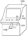
例えば、図6に示すゲーム機100に内蔵される。
101は内蔵されたホッパ、102はディスクdの受取口、103はディスクdの投入口である。
ホッパ101は、例えば特開平11-339086号(対応米国特許第6193598号)に開示のものである。
【0003】
ホッパ101の概要を、図7及び図8を参照して説明する。
水平ベース110に固定されたフレーム111に、約60度の角度でほぼ矩形のホッパベース112が取り付けられている。
ホッパベース112の裏面側にはモータ113が固定されている。
ホッパベース112の表側にディスク送り出し装置aを構成する回転ディスク114が配置されている。
【0004】
回転ディスク114は、前記モータ113から減速機(図示せず)を介して回転駆動される。
ボウル115は、ホッパホッパベース112に固定してある。
ボウル115は、回転ディスク114の外周を囲う円筒部115aとその円筒部115aに続くバケツ部115bを有する。
ボウル115のバケツ部115bに投入開口116が形成してある。
【0005】
次に図8も参照して送り出し装置aの構造を説明する。
回転ディスク114は、底板114aと円筒状の周壁114bとを有する有底円筒状に形成されている。
底板114aには、ディスクdが通過する通孔114cが等間隔で形成されている。
【0006】
回転ディスク114の下面には、通孔114cの間に送り爪114dが形成してある。
送り爪114dは、回転ディスク114の半径方向に対して傾斜している。
送り爪114dは、使用されるディスクdの厚みよりも小さいサイズで突出している。
【0007】
ホッパベース112の上面112aと回転ディスク114の通孔114c部の下面との間に、スペーサ121で画定された、ディスクdの厚みよりも僅かに厚いリング状の搬送空間122が形成されている。
したがって、回転ディスク114の回転により回転ディスク114とほぼ平行になって通孔112cを通過したディスクdは、搬送空間122に達し、ホッパベース112の上面112aに支えられつつ送り爪114dで押されて連れ回りされる。
【0008】
ホッパベース112上のスペーサ121の周りに楕円形の案内板123が固定してある。案内板123に小径端部に向かう出口案内部123aが形成してある。
【0009】
回転ディスク114の外周に位置するボウル115の円筒部115aにスリット状の出口124を形成してある。
出口124の一側に固定軸125に回転自在に取り付けた固定ガイドローラ126を配置してある。
【0010】
次に、カウントセンサ127の構造を説明する。
カウントセンサ127は、可動ガイドローラ128と揺動レバ130とセンサ136とを含んでいる。
可動ガイドローラ128は、固定軸129に回転自在に枢着された揺動レバー130の中間部の軸131に回転自在に取り付けてある。
【0011】
軸131は、ホッパベース112の裏面側に取り付けられたブラケット132に突設されている。
揺動レバー130は、ブラケット132に一端が取り付けられたスプリング133により反時計方向に回転される。
揺動レバー130は、通常、ストッパ134によって破線で示す不作動位置に保持されている。
【0012】
軸131は、揺動レバー130から突出してホッパベース112に形成した弧状長孔135を貫通してホッパベース112の上面112a側に突出しており、その突出端部に可動ガイドローラ128が支持されている。
【0013】
センサ136は光電式、磁気式等の無接触型であって、ブラケット132に固定されたブラケット137に固定され、揺動レバー130の存在を検知してカウント信号を出力する。
【0014】
次にディスク通路140を説明する。
出口124の側方において、間隔を空けてホッパベース112に固定したスペーサ141、142と、カバー143とで長方形の投出口144が形成してある。
ディスク通路140は、出口124から投出口144に達するディスクdの通路である。
可動ガイドローラ128は、ディスク通路140に配置されている。
【0015】
次にゲーム機100におけるディスクdの流れを説明する。
プレイヤーは、投入口103にディスクdを投入してゲームを行う。
投入されたディスクdは、図示しないダクトにより案内されて投入開口116からボウル115に入る。
【0016】
プレイにより当選すると、ゲーム機100の制御回路(図示せず)はディスクdの投出信号を出力する。
ゲーム機100の制御回路からコインの払い出し信号を受けると、ホッパ101のモータ113が回転される。
モータ113の回転により、回転ディスク114が矢印b方向に回転される。
【0017】
回転ディスク114の回転により、ボウル115内のディスクdは撹拌され、姿勢が変化する。
ディスクdは、通孔114cを通過し、ホッパベース112の上面112aに支持されつつ、送り爪114dによって押されて矢印b方向に送られる。
【0018】
送り爪114dにより押されるディスクdは、案内板123の出口案内部123aに接すると、矢印b方向の移動が阻止され、出口124に向け案内される。
次にディスクdは、固定ガイドローラ126に接した状態で送り爪114dにより更に押し出されるので、可動ガイドローラ128を時計方向に移動させる。
【0019】
ディスクdの中心が、固定ガイドローラ126の中心と可動ガイドローラ128の中心を結ぶ線上を越えた場合、スプリング133により可動ガイドローラ128を介してディスクdを弾いて、投出口144から投出する。
【0020】
投出されたディスクdは、ダクトにより案内されて受取口102に達する。
可動ガイドローラ128の移動により、揺動レバー130は時計方向に回転され、センサ136により検知される。
【0021】
センサ136は、投出ディスク数「1」を意味するカウント信号を出力する。
ゲーム機100の制御回路は、そのカウント信号をカウントする。
ディスクdの投出が継続して行われ、カウントが所定数になった場合、制御回路はモータ113の回転を停止し、ディスクdの投出を終了する。
【0022】
次に最近行われている不正例を説明する。
ワイヤ等で作成した器具を受取口102から差し込み、ホッパ101の投出口144に挿入し、可動ガイドローラ128を強制移動させて揺動レバー130をセンサ136に検出させることができるよう準備する。
【0023】
次にプレイし、例えば、当選によりディスクdが投出されている間に前記器具を使って可動ガイドローラ128を強制移動させ、恰もセンサ136がディスクdを検知している状態にし、これを継続する。
ゲーム機100の制御回路は、センサ136からオフ信号がないため「1」として認識し続ける。
【0024】
並行してディスクdが投出され続けるので、前記強制移動させている間に投出された分、一回の当選ディスク数よりも多くディスクdを入手できる。
この手口を繰り返し行って不正に多数のディスクdを入手する。
【0025】
【発明が解決しようとする課題】
本発明は前述の不正の実態に鑑み、ホッパの投出口から器具を挿入して、カウントセンサが恰もディスクを検出している状態を構築できないようにすることにより、前記不正を防止することを目的とする。
第2の目的は、簡単な装置により前記不正を防止できるようにすることである。
【0026】
【課題を解決するための手段】
この目的を達成するため、本発明のホッパは以下のように構成されている。
モータにより作動されディスクを送り出す送り出し装置と、前記送り出し装置から投出口へのディスク通路に配置したカウントセンサと、前記投出口の閉鎖位置と開放位置に選択的に移動可能なシャッタ装置と、前記シャッタ装置を前記モータのオンオフに連動して前記閉鎖位置と開放位置に選択移動する制御装置とを備え、
前記シャッタ装置は、前記投出口と並ぶように配され、当該投出口の閉鎖位置と開放位置に移動可能とされた板状のシャッタと、前記シャッタの両端部に形成された一対の同じ向きの方向に傾斜している長孔と、前記一対の長孔にスライド可能に挿入され、前記シャッタを前記長孔との傾斜により案内移動可能とさせる一対の固定された案内ピンと、前記シャッタと作動連結され、前記シャッタを前記モータのオン信号に基づきその閉鎖位置から開放位置へ移動させるためのシャッタ移動手段と、前記シャッタを前記投出口の閉鎖位置方向に常時附勢して閉鎖保持するシャッタ閉鎖保持手段と、より構成されていることを特徴とするシャッタを備えたホッパとしたものである。
【0027】
この構成によれば、ホッパが停止している場合、投出口をシャッタ装置で塞いでしまう。
一方、ディスクを投出する場合、シャッタ装置を移動して投出口が開放されるようにする。
したがって、ホッパがディスクを投出していないときに投出口はシャッタで塞がれているので器具を投出口へ挿入することができない。
【0028】
ホッパがディスクを投出しているときは、ディスクが勢い良く投出口から投出されているので、器具を投出口へ挿入することは極めて困難である。
これにより、投出口は実質的に全期間塞がれているので不正用の器具を投出口へ挿入することができないので、不正は完全に防止される。
【0029】
本発明は、前記制御装置が前記シャッタ装置を前記投出口の前記閉鎖位置から前記開放位置へ移動させた後、ディスク投出用の前記モータを作動させることが好ましい。この構成によれば、シャッタが投出口を開放した後にモータが回転ディスクを回転させてディスクの投出を開始するので、ディスクがシャッタで阻止されて投出口に詰まってしまうことを防止できる。
【0030】
【発明の実施の形態】
図1は第1実施例のシャッタ装置を装着したホッパの概略斜視図。
図2は第1実施例のシャッタ装置の構成図。
図3は第1実施例の制御回路のブロック図。
図4は第1実施例の作動説明用フローチャート。
図5は第2実施例のシャッタ装置の構成図。
【0031】
前記従来技術と同一部には同一符号を付し、異なる構成を説明する。
図1に示すように、hpが本発明に係るホッパである。
ホッパベース112に固定したシャッタ装置1が、投出口144に隣接して配置してある。
シャッタ装置1は、第2投出口2を有している。
シャッタ装置1は、図1に図示するようにホッパhpと別に作って後付してもよいし、ホッパhpの投出口144近傍に組み込んでもよい。
【0032】
次に図2を参照しシャッタ装置1の構造を説明する。
シャッタ装置1は、シャッタ10と、シャッタ10の移動装置20とよりなる。
まず、シャッタ10を説明する。
投出口144の直前方に矩形板状のシャッタ10が配置してある。
【0033】
シャッタ10は、シャッタ10を挟む一対の棒体11a、11bで構成される第1ガイド11、及び、棒体12a、12bで構成される同一構造の第2ガイド12の間に配置され、それらが第1ガイド11及び第2ガイド12に案内されて図2において左右及び上下方向に移動可能である。
【0034】
次に移動装置20の構造を説明する。
シャッタ10に、上下端部に右上がりに傾斜する直状の第1長孔13aと第2長孔13bが形成してある。
第1長孔13aと第2長孔13bに、第1固定ピン14a、第2固定ピン14bがそれぞれスライド可能に挿入してある。
【0035】
シャッタ10の上端部のピン15に、リンク16の下端部がピボット結合してある。
リンク16の上端部は、ピン17によってソレノイド18の鉄心19にピボット結合してある。
シャッタ10の下端部に引っかけた引っ張りスプリング21の他端は、固定ピン22に引っかけてある。
【0036】
ソレノイド18が励磁されていない場合、シャッタ10はスプリング21で引き下げられている。
これによりシャッタ10は、第1ピン14a、第2ピン14bと第1長孔13a、第2長孔13bによって左方へ移動され、シャッタ10の左端部で投出口144を覆っている。この位置がシャッタ10の閉鎖位置である。
【0037】
ソレノイド18が励磁された場合、シャッタ10は引き上げられる。
第1長孔13aと第2長孔13bの傾斜により、シャッタ10は引き上げられつつ右方へ移動する。
これによりシャッタ10は、図2に一点鎖線で図示するように投出口144の前方から外れる。
この位置がシャッタ10の開放位置である。
【0038】
次にホッパの制御装置30を図3を参照して説明する。
制御装置30は、CPU31と、ROM32と、RAM33とを含んでいる。
CPU31は、前述のセンサ136からのカウント信号cと、ゲーム機100の制御装置からの投出信号pと停止信号sを受ける。
【0039】
制御装置30は、RAM32に記憶している後述のプログラムに基づいてモータ113の作動と停止、ソレノイド18の励磁と消磁、及びセンサ136のカウント信号cpを出力する。
【0040】
次に図4のフローチャートも参照して第1実施例の作用を説明する。
まず、ホッパhpがゲーム機100の制御装置から投出信号pを受けていない場合、シャッタ10は図2の実線で示す位置にある。
【0041】
すなわち、ソレノイド18が消磁されてシャッタ10がスプリング21により下方へ引き下げられ、第1長孔13aと第2長孔13bの右上がりの傾斜により第1ピン14aと第2ピン14bによってシャッタ10が右方へ移動され、投出口144の前方の閉鎖位置にある。
【0042】
このとき、器具を受取口102、第2投出口2を介して投出口144に挿入しようとした場合、器具はシャッタ10に邪魔されて投出口144に挿入することが出来ない。
【0043】
次にゲーム機100の制御装置から投出信号pを受けたときの作用を図4のフローチャートを参照して説明する。
ステップs1において投出信号pの存在を確認してステップs2に進む。
【0044】
ステップs2において、ソレノイド18をオンにする。
これにより、シャッタ10は上方へ引き上げられつつ右方へ移動するので、図2に一点鎖線で示すように投出口144の前方から外れ、投出口144を開放する。
【0045】
次に、ステップs3において前記シャッタ10の移動に十分な時間計時後、ステップs4に進む。
ステップs4においてホッパhpのモータ113をオンにする。
回転ディスク114が回転されて前述のようにディスクdが一枚ずつ出口124から押し出され、可動ガイドローラ128によって弾かれ、投出口144を経由して第2投出口2から投出される。
【0046】
前記投出時の可動ガイドローラ128の移動によって揺動レバー130がセンサ136により検出され、センサ136はカウント信号cを出力する。
ゲーム機100の制御装置は、制御装置30からのカウント信号cpをカウントし、所定数をカウントし場合、停止信号sを出力する。
【0047】
次にステップs5において停止信号sがなければディスクdの投出を継続する。
このディスクdの投出時に、器具を第2投出口2から挿入しようとした場合、第2投出口2から勢い良くディスクdが連続的に投出されているため、邪魔されて挿入できない。
【0048】
ゲーム機100の制御装置が所定数のカウント信号を計数したとき、停止信号sを出力する。
ステップs5において停止信号sの存在を確認した場合、ステップs6に進む。
ステップs6では、モータ113を停止してディスクdの投出を終了する。
【0049】
次いでステップs7に進んでソレノイド18を消磁する。
ソレノイド18が消磁されると、シャッタ10はスプリング21により下方へ引き下げられつつ左方へ移動する。
これにより、シャッタ10は投出口144の前方に位置し、閉鎖する。
他の実施例として、カウント信号cのカウントをホッパhpの制御装置30で行って停止信号sを出力するようにしてもよい。
【0050】
次に第2実施例を図5を参照して説明する。
シャッタ40は、櫛歯状に形成してある。
シャッタ40の矩形の柄部41は、固定ガイド42にスライド可能に挿入してある。
【0051】
柄部41の端部のピン43にソレノイド44の鉄心45がピボット結合してある。
鉄心45に固定したリテーナ46とソレノイド44との間に装着した圧縮スプリング47により、鉄心45を図5において右方に押している。
【0052】
ソレノイド44が消磁されている場合、鉄心45はスプリング47によって右方へ移動され、鉄心45に固定されているリテーナ48がソレノイド44によってストップされ、シャッタ40が投出口144の前方の閉鎖位置にあり、投出口144を実質的に塞ぐ。
【0053】
ソレノイド44が励磁された場合、鉄心45が左方へ引かれるので、シャッタ40は同方向へ移動し、投出口144の前方から外れ、開放位置になる。
ソレノイド44は、第1の実施例と同一のプログラムで制御装置30によってオンオフされる。
したがって、作動は第1の実施例と同一なので説明を省略する。
【0054】
【図面の簡単な説明】
【図1】図1は第1実施例のシャッタ装置を装着したホッパの概略斜視図。
【図2】図2は第1実施例のシャッタ装置の構成図。
【図3】図3は第1実施例の制御回路のブロック図。
【図4】図4は第1実施例の作動説明用フローチャート。
【図5】図5は第2実施例のシャッタ装置の構成図。
【図6】図6はホッパが装着されるゲーム機の概略斜視図。
【図7】図7は、従来のホッパの斜視図。
【図8】図8は、従来のホッパの説明図
【0059】
【符号の説明】
1 シャッタ装置
10、40 シャッタ
30 制御装置
113 モータ
114 回転ディスク
127 カウントセンサ
140 ディスク通路
144 投出口[0001]
[Technical field to which the invention belongs]
The present invention relates to a hopper that ejects discs one by one.
The “disc” used in the present specification includes coins as currency, as well as substitute money such as medals and tokens of game machines, or similar items.
[0002]
[Prior art]
The hopper is built in a game machine such as a slot machine.
For example, it is built in the
101 is a built-in hopper, 102 is a receiving port for the disk d, and 103 is a slot for the disk d.
The
[0003]
An outline of the
A substantially
A
On the front side of the
[0004]
The rotating
The
The
An
[0005]
Next, the structure of the delivery device a will be described with reference to FIG.
The rotating
Through
[0006]
On the lower surface of the rotating
The
The
[0007]
Between the upper surface 112a of the
Therefore, the disk d that has passed through the through hole 112c substantially parallel to the rotating
[0008]
An
[0009]
A slit-
A
[0010]
Next, the structure of the
The
The
[0011]
The
The
The
[0012]
The
[0013]
The
[0014]
Next, the
A
The
The
[0015]
Next, the flow of the disk d in the
The player plays the game by inserting the disk d into the
The loaded disc d is guided by a duct (not shown) and enters the
[0016]
When winning by playing, a control circuit (not shown) of the
When a coin payout signal is received from the control circuit of the
Due to the rotation of the
[0017]
Due to the rotation of the
The disk d passes through the through
[0018]
When the disk d pushed by the
Next, the disk d is further pushed out by the
[0019]
When the center of the disk d exceeds the line connecting the center of the fixed
[0020]
The ejected disc d is guided by the duct and reaches the receiving
As the
[0021]
The
The control circuit of the
When the disk d is continuously ejected and the count reaches a predetermined number, the control circuit stops the rotation of the
[0022]
Next, a recent example of fraud will be described.
A tool made of a wire or the like is inserted from the receiving
[0023]
Next, play, for example, while the disk d is thrown out by winning, the
The control circuit of the
[0024]
Since the disk d continues to be thrown out in parallel, more disks d can be obtained than the number of winning disks at one time by the amount thrown out during the forced movement.
Repeat this technique to obtain a large number of discs illegally.
[0025]
[Problems to be solved by the invention]
The present invention has been made in view of the above-mentioned fraudulent situation, and an object is to prevent the fraud by inserting a tool from a hopper outlet and preventing the count sensor from detecting a disc. And
A second object is to prevent the fraud with a simple device.
[0026]
[Means for Solving the Problems]
In order to achieve this object, the hopper of the present invention is configured as follows.
A feeding device feeds the disc is actuated by a motor, and a count sensor disposed in the disk path to the throw-out port from the delivery device, and selectively moveable shutter device to open and closed positions of the dispensing port, the shutter A control device that selectively moves the device to the closed position and the open position in conjunction with on / off of the motor ;
The shutter device is arranged in line with the outlet, and has a plate-like shutter that can be moved to a closed position and an open position of the outlet, and a pair of same orientations formed at both ends of the shutter. A pair of fixed guide pins that are slidably inserted into the pair of long holes and that allow the shutter to be guided and moved by tilting with the long holes, and an operating connection with the shutter A shutter moving means for moving the shutter from its closed position to its open position based on an ON signal of the motor, and shutter closing holding for constantly closing and holding the shutter in the direction of the closing position of the outlet And a hopper provided with a shutter characterized by being configured.
[0027]
According to this configuration, when the hopper is stopped, the outlet is closed by the shutter device.
On the other hand, when the disc is to be thrown out, the shutter device is moved so that the outlet is opened.
Therefore, when the hopper is not throwing out the disc, the throwing outlet is blocked by the shutter, so that the instrument cannot be inserted into the throwing outlet.
[0028]
When the hopper is throwing the disc, it is very difficult to insert the instrument into the throw-out port because the disc is being thrown out from the throw-out port vigorously.
As a result, since the outlet is substantially closed for the entire period, an illegal instrument cannot be inserted into the outlet, so that the fraud is completely prevented.
[0029]
The present invention is, after the control device has moved to the open position the shutter device from the closed position of the dispensing port, it is preferable to operate the motor for the disk dispensing. According to this configuration, since the motor starts rotating the rotating disk after the shutter has opened the outlet, the disk is prevented from being blocked by the shutter and clogging the outlet.
[0030]
DETAILED DESCRIPTION OF THE INVENTION
FIG. 1 is a schematic perspective view of a hopper equipped with the shutter device of the first embodiment.
FIG. 2 is a configuration diagram of the shutter device of the first embodiment.
FIG. 3 is a block diagram of the control circuit of the first embodiment.
FIG. 4 is a flowchart for explaining the operation of the first embodiment.
FIG. 5 is a block diagram of the shutter device of the second embodiment.
[0031]
The same parts as those in the prior art are denoted by the same reference numerals, and different configurations will be described.
As shown in FIG. 1, hp is a hopper according to the present invention.
A
The
The
[0032]
Next, the structure of the
The
First, the
A rectangular plate-shaped
[0033]
The
[0034]
Next, the structure of the moving
The
A
[0035]
The lower end portion of the
The upper end of the
The other end of the
[0036]
When the
Thus, the
[0037]
When the
Due to the inclination of the first
As a result, the
This position is the opening position of the
[0038]
Next, the control device 30 for the hopper will be described with reference to FIG.
The control device 30 includes a
The
[0039]
The control device 30 outputs the operation and stop of the
[0040]
Next, the operation of the first embodiment will be described with reference to the flowchart of FIG.
First, when the hopper hp has not received the throwing signal p from the control device of the
[0041]
That is, the
[0042]
At this time, if an instrument is to be inserted into the
[0043]
Next, the operation when the throwing signal p is received from the control device of the
In step s1, the presence of the projection signal p is confirmed, and the process proceeds to step s2.
[0044]
In step s2, the
As a result, the
[0045]
Next, after measuring time sufficient for the movement of the
In step s4, the
As described above, the
[0046]
The
The control device of the
[0047]
Next, if there is no stop signal s in step s5, the ejection of the disk d is continued.
If the instrument is to be inserted from the
[0048]
When the control device of the
When the presence of the stop signal s is confirmed in step s5, the process proceeds to step s6.
In step s6, the
[0049]
Next, the routine proceeds to step s7, where the
When the
Thereby, the
As another embodiment, the count signal c may be counted by the control device 30 of the hopper hp and the stop signal s may be output.
[0050]
Next, a second embodiment will be described with reference to FIG.
The
A
[0051]
An
The
[0052]
When the
[0053]
When the
The
Therefore, the operation is the same as that of the first embodiment, and the description is omitted.
[0054]
[Brief description of the drawings]
FIG. 1 is a schematic perspective view of a hopper equipped with a shutter device according to a first embodiment.
FIG. 2 is a configuration diagram of a shutter device according to the first embodiment;
FIG. 3 is a block diagram of a control circuit of the first embodiment.
FIG. 4 is a flowchart for explaining the operation of the first embodiment.
FIG. 5 is a configuration diagram of a shutter device according to a second embodiment.
FIG. 6 is a schematic perspective view of a game machine to which a hopper is attached.
FIG. 7 is a perspective view of a conventional hopper.
FIG. 8 is an explanatory diagram of a conventional hopper.
[Explanation of symbols]
1 Shutter device
10, 40 Shutter
30 Control unit
113 motor
114 rotating disc
127 count sensor
140 disc passage
144 outlet
Claims (2)
前記シャッタ装置( 1 )は、前記投出口( 144 )と並ぶように配され、当該投出口( 144 )の閉鎖位置と開放位置に移動可能とされた板状のシャッタ( 10 )と、前記シャッタ( 10 )の両端部に形成された一対の同じ向きの方向に傾斜している長孔( 13 a、 13 b)と、前記一対の長孔( 13 a、 13 b)にスライド可能に挿入され、前記シャッタ( 10 )を前記長孔との傾斜により案内移動可能とさせる一対の固定された案内ピン( 14 a、 14 b)と、前記シャッタ( 10 )と作動連結され、前記シャッタを前記モータのオン信号に基づきその閉鎖位置から開放位置へ移動させるためのシャッタ移動手段( 20 )と、前記シャッタ( 10 )を前記投出口( 144 )の閉鎖位置方向に常時附勢して閉鎖保持するシャッタ閉鎖保持手段( 21 )と、より構成されていることを特徴とするシャッタを備えたホッパ。 A delivery device (a) that is actuated by a motor to deliver the disc, a count sensor (127) disposed in a disc passage (140) from the delivery device (a) to the delivery port (144), and the delivery port (144) A shutter device (1) that can be selectively moved to a closed position and an open position, and a control device that selectively moves the shutter device (1) to the closed position and the open position in conjunction with on / off of the motor (113) ( 30) and equipped with a,
The shutter device (1), the disposed to align with the throw-out port (144), with the dispensing port (144) movable with the plate-like shutter in the closed position and the open position (10), the shutter and both end portions formed in a pair of long holes which are inclined in the same direction of orientation of the (10) (13 a, 13 b), slidably inserted into the pair of long holes (13 a, 13 b) A pair of fixed guide pins ( 14 a, 14 b) that enable the shutter ( 10 ) to be guided and moved by tilting with the elongated hole, and the shutter ( 10 ), and the shutter is connected to the motor A shutter moving means ( 20 ) for moving the shutter from the closed position to the open position based on the ON signal of the shutter, and a shutter for constantly closing the shutter ( 10 ) by energizing the shutter ( 144 ) toward the closed position of the outlet ( 144 ) The closure holding means ( 21 ) and consists of A hopper provided with a shutter.
Priority Applications (2)
| Application Number | Priority Date | Filing Date | Title |
|---|---|---|---|
| JP2001177933A JP4258753B2 (en) | 2001-06-13 | 2001-06-13 | Hopper with shutter |
| US10/166,946 US6823977B2 (en) | 2001-06-13 | 2002-06-11 | Coin hopper with a shutter |
Applications Claiming Priority (1)
| Application Number | Priority Date | Filing Date | Title |
|---|---|---|---|
| JP2001177933A JP4258753B2 (en) | 2001-06-13 | 2001-06-13 | Hopper with shutter |
Publications (3)
| Publication Number | Publication Date |
|---|---|
| JP2002366999A JP2002366999A (en) | 2002-12-20 |
| JP2002366999A5 JP2002366999A5 (en) | 2005-10-27 |
| JP4258753B2 true JP4258753B2 (en) | 2009-04-30 |
Family
ID=19018707
Family Applications (1)
| Application Number | Title | Priority Date | Filing Date |
|---|---|---|---|
| JP2001177933A Expired - Lifetime JP4258753B2 (en) | 2001-06-13 | 2001-06-13 | Hopper with shutter |
Country Status (2)
| Country | Link |
|---|---|
| US (1) | US6823977B2 (en) |
| JP (1) | JP4258753B2 (en) |
Cited By (1)
| Publication number | Priority date | Publication date | Assignee | Title |
|---|---|---|---|---|
| JP2013252392A (en) * | 2012-06-08 | 2013-12-19 | Mina Technology Kk | Coin putout device and game machine |
Families Citing this family (5)
| Publication number | Priority date | Publication date | Assignee | Title |
|---|---|---|---|---|
| US20050009464A1 (en) * | 2003-05-15 | 2005-01-13 | Aruze Corp. | Payment object dispensing machine |
| JP4474583B2 (en) * | 2004-03-18 | 2010-06-09 | 旭精工株式会社 | Safe coin dispenser |
| CN100373413C (en) * | 2005-07-25 | 2008-03-05 | 上海华铭智能终端设备有限公司 | Bucket turning controlled institution |
| US8517163B2 (en) * | 2005-08-02 | 2013-08-27 | Telequip Corporation | Coin handling system for validation, sorting, and dispensing coins |
| JP6002929B2 (en) * | 2013-01-28 | 2016-10-05 | 旭精工株式会社 | Coin dispenser |
Family Cites Families (12)
| Publication number | Priority date | Publication date | Assignee | Title |
|---|---|---|---|---|
| US3371762A (en) * | 1965-09-17 | 1968-03-05 | Lion Mfg Corp | Coin chute wire lockout and control |
| CH646000A5 (en) * | 1979-10-01 | 1984-10-31 | Autelca Ag | Automatic coin collector |
| US4589433A (en) * | 1983-12-07 | 1986-05-20 | Asahi Seiko Kabushiki Kaisha | Coin dispensing apparatus |
| DE3538717A1 (en) * | 1985-10-31 | 1987-05-07 | Standard Elektrik Lorenz Ag | Coin-insertion device for coin-operated automatic machines |
| US4842120A (en) * | 1988-04-29 | 1989-06-27 | Mars, Incorporated | Jam reducing apparatus for use in a coin operated machine |
| US5046989A (en) * | 1988-08-18 | 1991-09-10 | Jack Dass | Coin storage and dispensing apparatus |
| US5402871A (en) * | 1993-10-20 | 1995-04-04 | Set-O-Matic, Inc. | Drop coin mechanism |
| US5484334A (en) * | 1994-04-01 | 1996-01-16 | Evdokimo; Allen J. | Coin handling apparatus with coin filter and improved coin interlock |
| TW304608U (en) * | 1995-02-23 | 1997-05-01 | Asahi Seiko Co Ltd | Coin conveying device |
| GB9523405D0 (en) * | 1995-11-16 | 1996-01-17 | Coin Controls | Coin dispensing mechanism |
| JP3792766B2 (en) * | 1996-01-30 | 2006-07-05 | アルゼ株式会社 | Coin dispensing device for gaming machines |
| JP3516007B2 (en) * | 1997-07-09 | 2004-04-05 | 旭精工株式会社 | Disc sending device |
-
2001
- 2001-06-13 JP JP2001177933A patent/JP4258753B2/en not_active Expired - Lifetime
-
2002
- 2002-06-11 US US10/166,946 patent/US6823977B2/en not_active Expired - Lifetime
Cited By (1)
| Publication number | Priority date | Publication date | Assignee | Title |
|---|---|---|---|---|
| JP2013252392A (en) * | 2012-06-08 | 2013-12-19 | Mina Technology Kk | Coin putout device and game machine |
Also Published As
| Publication number | Publication date |
|---|---|
| US6823977B2 (en) | 2004-11-30 |
| US20020189919A1 (en) | 2002-12-19 |
| JP2002366999A (en) | 2002-12-20 |
Similar Documents
| Publication | Publication Date | Title |
|---|---|---|
| JP2007037812A (en) | Game machine | |
| JP4258753B2 (en) | Hopper with shutter | |
| JP3864388B2 (en) | Disc body sorting device | |
| JP2007029616A (en) | Game machine | |
| JP4478617B2 (en) | Medal feeder | |
| EP1634251B1 (en) | Coin dispensing apparatus | |
| JP2007029613A (en) | Game machine | |
| JP4749300B2 (en) | Transport device | |
| JP4222970B2 (en) | Collective insertion mechanism of game medals for inter-machines | |
| JP3550370B2 (en) | Coin change machine | |
| JP2004174000A (en) | Token delivery device | |
| JP5129361B2 (en) | Pachinko machine | |
| JP4623761B1 (en) | Medal selector and medal-type game machine using the medal selector | |
| JP4836151B1 (en) | Medal selector and medal game machine | |
| JP2001067519A (en) | Medal sorting device | |
| JP4318068B2 (en) | Coin hopper | |
| JP2003062320A (en) | Game machine | |
| JP4527620B2 (en) | Medal feeder | |
| JP4684922B2 (en) | Medals lending machine | |
| JP4953489B2 (en) | Medal selector and medal game machine | |
| JP4444903B2 (en) | Medals lending machine | |
| JP2008073122A (en) | Token dispenser | |
| JP2008080033A (en) | Carrier | |
| JP2002150360A (en) | Banknote discriminator | |
| JP2008073123A (en) | Token dispenser |
Legal Events
| Date | Code | Title | Description |
|---|---|---|---|
| A521 | Request for written amendment filed |
Free format text: JAPANESE INTERMEDIATE CODE: A523 Effective date: 20050722 |
|
| A621 | Written request for application examination |
Free format text: JAPANESE INTERMEDIATE CODE: A621 Effective date: 20050722 |
|
| A977 | Report on retrieval |
Free format text: JAPANESE INTERMEDIATE CODE: A971007 Effective date: 20081020 |
|
| A131 | Notification of reasons for refusal |
Free format text: JAPANESE INTERMEDIATE CODE: A131 Effective date: 20081111 |
|
| A521 | Request for written amendment filed |
Free format text: JAPANESE INTERMEDIATE CODE: A523 Effective date: 20081225 |
|
| TRDD | Decision of grant or rejection written | ||
| A01 | Written decision to grant a patent or to grant a registration (utility model) |
Free format text: JAPANESE INTERMEDIATE CODE: A01 Effective date: 20090129 |
|
| A01 | Written decision to grant a patent or to grant a registration (utility model) |
Free format text: JAPANESE INTERMEDIATE CODE: A01 |
|
| A61 | First payment of annual fees (during grant procedure) |
Free format text: JAPANESE INTERMEDIATE CODE: A61 Effective date: 20090129 |
|
| FPAY | Renewal fee payment (event date is renewal date of database) |
Free format text: PAYMENT UNTIL: 20120220 Year of fee payment: 3 |
|
| R150 | Certificate of patent or registration of utility model |
Ref document number: 4258753 Country of ref document: JP Free format text: JAPANESE INTERMEDIATE CODE: R150 Free format text: JAPANESE INTERMEDIATE CODE: R150 |
|
| FPAY | Renewal fee payment (event date is renewal date of database) |
Free format text: PAYMENT UNTIL: 20130220 Year of fee payment: 4 |
|
| R250 | Receipt of annual fees |
Free format text: JAPANESE INTERMEDIATE CODE: R250 |
|
| FPAY | Renewal fee payment (event date is renewal date of database) |
Free format text: PAYMENT UNTIL: 20130220 Year of fee payment: 4 |
|
| FPAY | Renewal fee payment (event date is renewal date of database) |
Free format text: PAYMENT UNTIL: 20130220 Year of fee payment: 4 |
|
| R250 | Receipt of annual fees |
Free format text: JAPANESE INTERMEDIATE CODE: R250 |
|
| R250 | Receipt of annual fees |
Free format text: JAPANESE INTERMEDIATE CODE: R250 |
|
| R250 | Receipt of annual fees |
Free format text: JAPANESE INTERMEDIATE CODE: R250 |
|
| R250 | Receipt of annual fees |
Free format text: JAPANESE INTERMEDIATE CODE: R250 |
|
| R250 | Receipt of annual fees |
Free format text: JAPANESE INTERMEDIATE CODE: R250 |
|
| R250 | Receipt of annual fees |
Free format text: JAPANESE INTERMEDIATE CODE: R250 |
|
| R250 | Receipt of annual fees |
Free format text: JAPANESE INTERMEDIATE CODE: R250 |
|
| R250 | Receipt of annual fees |
Free format text: JAPANESE INTERMEDIATE CODE: R250 |
|
| R250 | Receipt of annual fees |
Free format text: JAPANESE INTERMEDIATE CODE: R250 |
|
| EXPY | Cancellation because of completion of term |