JP4299853B2 - Method and program for forming integrated circuit features - Google Patents
Method and program for forming integrated circuit features Download PDFInfo
- Publication number
- JP4299853B2 JP4299853B2 JP2006294951A JP2006294951A JP4299853B2 JP 4299853 B2 JP4299853 B2 JP 4299853B2 JP 2006294951 A JP2006294951 A JP 2006294951A JP 2006294951 A JP2006294951 A JP 2006294951A JP 4299853 B2 JP4299853 B2 JP 4299853B2
- Authority
- JP
- Japan
- Prior art keywords
- edge
- image transfer
- based image
- shape
- shapes
- Prior art date
- Legal status (The legal status is an assumption and is not a legal conclusion. Google has not performed a legal analysis and makes no representation as to the accuracy of the status listed.)
- Expired - Fee Related
Links
Images
Classifications
-
- G—PHYSICS
- G03—PHOTOGRAPHY; CINEMATOGRAPHY; ANALOGOUS TECHNIQUES USING WAVES OTHER THAN OPTICAL WAVES; ELECTROGRAPHY; HOLOGRAPHY
- G03F—PHOTOMECHANICAL PRODUCTION OF TEXTURED OR PATTERNED SURFACES, e.g. FOR PRINTING, FOR PROCESSING OF SEMICONDUCTOR DEVICES; MATERIALS THEREFOR; ORIGINALS THEREFOR; APPARATUS SPECIALLY ADAPTED THEREFOR
- G03F1/00—Originals for photomechanical production of textured or patterned surfaces, e.g., masks, photo-masks, reticles; Mask blanks or pellicles therefor; Containers specially adapted therefor; Preparation thereof
- G03F1/68—Preparation processes not covered by groups G03F1/20 - G03F1/50
- G03F1/70—Adapting basic layout or design of masks to lithographic process requirements, e.g., second iteration correction of mask patterns for imaging
Landscapes
- Physics & Mathematics (AREA)
- General Physics & Mathematics (AREA)
- Preparing Plates And Mask In Photomechanical Process (AREA)
- Design And Manufacture Of Integrated Circuits (AREA)
Description
本発明は、一般に、集積回路の形成に関し、詳細には、エッジ・ベースのパターン転写(edge based pattern transfer)プロセスにより前記集積回路の形成を最適化するマスク・セットに集積回路パターンを変換するための方法に関する。 The present invention relates generally to the formation of integrated circuits, and more particularly to converting integrated circuit patterns into a mask set that optimizes the formation of the integrated circuit by an edge based pattern transfer process. Concerning the method.
集積回路(「IC」)業界は、電子デバイスがより高速になるとともに無限に小さくなるよう努力している。したがって、IC業界は、寸法制御(dimensional control)が改善されたIC構造体(IC feature)を形成する方法を求める要求によって推進されている。寸法制御が改善されたIC形成により、さらに小さいIC構造体が作成され、それにより、ICの回路密度が増加する。回路密度の増加により、より高いチップ性能がもたらされる。したがって、寸法制御が改善されたIC構造体を形成する改良型の方法を開発することにより、相当な経済的利点を得ることができる。2通りの従来技術のIC形成方法としては、光リソグラフィ(opticallithography)と側壁イメージ転写(「SIT:sidewall image transfer」)を含む。 The integrated circuit ("IC") industry strives for electronic devices to become faster and infinitely smaller. Accordingly, the IC industry is driven by the need for a method of forming IC features with improved dimensional control. IC formation with improved dimensional control creates smaller IC structures, thereby increasing the circuit density of the IC. Increased circuit density results in higher chip performance. Accordingly, considerable economic advantages can be obtained by developing an improved method of forming an IC structure with improved dimensional control. Two prior art IC formation methods include optical lithography and sidewall image transfer ("SIT").
一方の従来技術のIC形成方法である光リソグラフィは、半導体基板とこのような基板上に付着させた様々なフィルムを光源の使用によって順次変更するパターン形成操作を含む。感光性ポリマ・フィルム、たとえば、フォトレジストまたはレジストの層を基板上にコーティングし、続いて、マスタ・ステンシル、すなわち、フォトマスクまたはマスクを通してレジストを光源に対して露光する。マスクは、レジストに転写された線および空間などのパターン形成されたIC構造体を含む。レジストを露光した後、光リソグラフィ・ツールはレジストを溶剤に浸す。溶剤は、レジストに転写された構造体を画定する。 On the other hand, photolithography, which is a conventional IC forming method, includes a pattern forming operation in which a semiconductor substrate and various films deposited on the substrate are sequentially changed by using a light source. A photosensitive polymer film, such as a layer of photoresist or resist, is coated on the substrate, followed by exposing the resist to a light source through a master stencil, ie, a photomask or mask. The mask includes patterned IC structures such as lines and spaces transferred to the resist. After exposing the resist, the photolithography tool immerses the resist in a solvent. The solvent defines the structure transferred to the resist.
光リソグラフィ・ツールは光源の波長によって制限されるので、この光リソグラフィという従来技術の方法は問題を含むものである。たとえば、IC構造体が45.0nmという線幅まで小さくなると、光リソグラフィではこのような小さい線幅のIC構造体を形成できないことがますます問題を含むものになる。無限に小さくなるIC構造体を形成することに加えて、光リソグラフィは、寸法制御が高まったIC構造体を作成する能力を持たなければならない。たとえば、電界効果トランジスタのゲートは、光リソグラフィによって形成されたこのような構造体の1つであり、その公称幅の±10%を上回るように制御されなければならない。しかし、回折効果(diffraction effect)により、このように寸法制御されたIC構造体を生み出す(deliver)光リソグラフィの能力が制限される。光リソグラフィがIC構造体を提供する際の正確さは、転写中のIC構造体の解像度に反比例する。光リソグラフィによって生産されるIC構造体は、光リソグラフィ・ツールの最小解像度を上回る線幅に制限され、それは最終的にレジストを露光するために光リソグラフィが使用する光源の波長(「λ」)によって制限される。少なくともこれらの理由により、光リソグラフィは不十分なものである。 Since the optical lithography tool is limited by the wavelength of the light source, this prior art method of optical lithography is problematic. For example, when the IC structure is reduced to a line width of 45.0 nm, it becomes more and more problematic that an IC structure having such a small line width cannot be formed by optical lithography. In addition to forming infinitely small IC structures, photolithography must have the ability to create IC structures with increased dimensional control. For example, the gate of a field effect transistor is one such structure formed by photolithography and must be controlled to exceed ± 10% of its nominal width. However, the diffraction effect limits the ability of optical lithography to deliver such dimensionally controlled IC structures. The accuracy with which optical lithography provides an IC structure is inversely proportional to the resolution of the IC structure being transferred. IC structures produced by optical lithography are limited to line widths that exceed the minimum resolution of the optical lithography tool, which ultimately depends on the wavelength of the light source ("λ") that optical lithography uses to expose the resist. Limited. For at least these reasons, photolithography is inadequate.
もう1つの従来技術のIC形成方法であるSITと、さらにエッジ・ベースのイメージ転写プロセスは、メサ(mesa)の側壁上にエッチマスキング媒体(etch-masking medium)、たとえば、窒化物を付着させることと、メサを除去することを含み、それにより側壁構造が残される。側壁構造は、狭いIC構造体のパターン形成のための1次イメージ転写媒体として作用する。 Another prior art IC formation method, SIT and also an edge-based image transfer process, deposits an etch-masking medium, eg, nitride, on the mesa sidewall. And removing the mesa, thereby leaving a sidewall structure. The sidewall structure acts as a primary image transfer medium for patterning narrow IC structures.
SITは光リソグラフィという従来技術の方法より寸法制御が改善されているが、SIT操作ごとに1つのIC構造体サイズしか形成できず、閉ループ・トポグラフィしか作成できず、SITは包括的ではないIC構造体形状ライブラリを有し、換言すれば、SITでは特定のIC構造体形状しか形成できないので、SITという従来技術の方法は問題を含むものである。寸法制御は重要であるが、場合によっては、他の考慮事項、たとえば、構造体サイズの拡大、チップ性能、およびコストに対して、寸法制御が2次的なものになる。SITでは、このような他の考慮事項が最も重要なものになる場合、IC設計者は所望のIC構造体を作成するためにSITから光リソグラフィに頼らなければならない。このような考慮事項に加えて、SITでは限られた数の形状、より具体的には、閉ループ形状しか作成できないので、SITは不利である。SITでは形成できない形状を形成しなければならない場合、IC設計者はSITから光リソグラフィに頼らなければならない。SITが問題を含むもう1つの理由は、エッジ・ベースの画像処理プロセスを実行するために必要なマスク・セットにICレイアウトを変換することに関連する難題である。要するに、SITは寸法制御については改善されているが、光リソグラフィに対する依存状態を完全に排除するわけではない。少なくともこれらの理由により、SIT単独では不十分である。SITはエッジ・ベースのイメージ転写プロセスであるが、位相シフト(alternating phase shift)はSITと同様の利点および欠点を有するもう1つのエッジ・ベースのイメージ転写プロセスであることに留意されたい。 SIT has improved dimensional control over the prior art method of photolithography, but only one IC structure size can be formed per SIT operation, only closed-loop topography can be created, and SIT is not a comprehensive IC structure Since it has a body shape library, in other words, only a specific IC structure shape can be formed by SIT, the prior art method of SIT is problematic. While dimensional control is important, in some cases, dimensional control is secondary to other considerations such as structure size increase, chip performance, and cost. In SIT, if such other considerations become the most important, IC designers must rely on optical lithography from SIT to create the desired IC structure. In addition to such considerations, SIT is disadvantageous because only a limited number of shapes can be created in SIT, more specifically, closed loop shapes. When a shape that cannot be formed by SIT must be formed, the IC designer must rely on optical lithography from SIT. Another reason SIT is problematic is the challenge associated with converting the IC layout to the mask set necessary to perform the edge-based image processing process. In short, SIT has improved dimensional control but does not completely eliminate dependence on optical lithography. For at least these reasons, SIT alone is not sufficient. It should be noted that while SIT is an edge-based image transfer process, altering phase shift is another edge-based image transfer process that has similar advantages and disadvantages as SIT.
当技術分野で必要とされているものは、寸法制御、チップ性能、およびコストなどの考慮事項に基づいてエッジ・ベースのイメージ転写マスクの使用を最適化する最終マスク・セットを作成し、ブロックおよび光リソグラフィ・マスクにより集積回路を作成する際の欠点を補償する、集積回路を形成するための改良された方法である。 What is needed in the art is to create a final mask set that optimizes the use of edge-based image transfer masks based on considerations such as dimensional control, chip performance, and cost, and blocks and An improved method for forming an integrated circuit that compensates for the disadvantages of creating an integrated circuit with a photolithographic mask.
本発明は、集積回路を形成するためのエッジ・ベースのイメージ転写プロセスを最適化する複数のマスクに集積回路パターンを変換するための方法を対象とする。集積回路パターン内に最適化された数のエッジ・ベースのイメージ転写形状を形成するために、エッジ・ベースのイメージ転写マスクが生成される。各集積回路パターンは複数の集積回路形状で構成される。 The present invention is directed to a method for converting an integrated circuit pattern into a plurality of masks that optimize an edge-based image transfer process to form an integrated circuit. An edge-based image transfer mask is generated to form an optimized number of edge-based image transfer shapes within the integrated circuit pattern. Each integrated circuit pattern is composed of a plurality of integrated circuit shapes.
本発明の第1の実施形態により、最適化された数のエッジ・ベースのイメージ転写形状の残余セクションを除去するためにブロック・マスクが生成され、残りの集積回路形状を形成するためにリソグラフィ・マスクが生成される。 In accordance with the first embodiment of the present invention, a block mask is generated to remove an optimized number of edge-based image transfer shape residual sections, and a lithography mask is formed to form the remaining integrated circuit shape. A mask is generated.
本発明の第2の実施形態により、集積回路パターン内の最適化された数のエッジ・ベースのイメージ転写形状のために、複数の集積回路形状内でエッジ・ベースのイメージ転写形状セットが選択される。エッジ・ベースのイメージ転写形状の生成時のエラーに基づいて、そのセットが反復的に削減される。 According to a second embodiment of the present invention, an edge-based image transfer shape set is selected in a plurality of integrated circuit shapes for an optimized number of edge-based image transfer shapes in the integrated circuit pattern. The The set is iteratively reduced based on errors when generating edge-based image transfer shapes.
本発明の第3の実施形態により、集積回路パターン内の最適化された数のエッジ・ベースのイメージ転写形状のために、複数内でエッジ・ベースのイメージ転写形状セットが選択される。セット内のそれぞれのエッジ・ベースのイメージ転写形状は、バイナリのエッジ・ベースのイメージ転写製造オプションを含む。それぞれのエッジ・ベースのイメージ転写形状について、最も好都合なエッジ・ベースのイメージ転写バイナリ製造オプションが選択的に選ばれる。それにより、エッジ・ベースのイメージ転写形状の最終セットが作成される。 According to a third embodiment of the present invention, an edge-based image transfer shape set is selected in the plurality for an optimized number of edge-based image transfer shapes in the integrated circuit pattern. Each edge-based image transfer shape in the set includes a binary edge-based image transfer manufacturing option. For each edge-based image transfer shape, the most convenient edge-based image transfer binary manufacturing option is selectively chosen. This creates a final set of edge-based image transfer shapes.
本発明の第4の実施形態により、ICパターン内の最適化された数のエッジ・ベースのイメージ転写形状のために、複数内でエッジ・ベースのイメージ転写形状セットが選択され、そのセットの周りに排除エリア(exclusion area)が画定され、エッジ・ベースのイメージ拡張に応じて少なくとも部分的なIC障害を引き起こす恐れがあるエッジ・ベースのイメージ転写形状の拡張を実質的に防止する。 According to a fourth embodiment of the present invention, an edge-based image transfer shape set is selected in a plurality for an optimized number of edge-based image transfer shapes in an IC pattern, An exclusion area is defined to substantially prevent edge-based image transfer shape expansion that can cause at least partial IC failure in response to edge-based image expansion.
本発明は、集積回路を形成するために光リソグラフィと連携したエッジ・ベースのイメージ転写の使用を最適化するものである。このように実行する際に、本発明では、エッジ・ベースのイメージ転写によって二重構造体が作成されるのでコストを節約し、厳密な寸法制御でエッジ・ベースのイメージ転写プロセスが作成されるので回路密度について改善され、さらに継続的に光リソグラフィに依存することによるエッジ・ベースのイメージ転写プロセスの欠点を補償する。 The present invention optimizes the use of edge-based image transfer in conjunction with photolithography to form integrated circuits. In doing so, the present invention creates a dual structure by edge-based image transfer, thus saving cost and creating an edge-based image transfer process with strict dimensional control. It improves on circuit density and further compensates for the shortcomings of edge-based image transfer processes by relying on photolithography continuously.
少なくとも上記の理由により、本発明は、集積回路の形成について改善されている。 For at least the above reasons, the present invention is improved for the formation of integrated circuits.
本発明の特徴および要素特性は、特許請求の範囲に詳細に示されている。図面は、例示のみを目的としており、一定の縮尺で描かれているわけではない。さらに、図面内の同様の番号は同様の特徴を表している。しかし、本発明自体は、構成および動作方法のいずれについても、添付図面に併せて読んだときに、以下に示す詳細な説明を参照することによって最も良く理解することができる。 The features and element characteristics of the invention are set forth with particularity in the appended claims. The drawings are for illustrative purposes only and are not drawn to scale. Moreover, like numbers in the drawings represent like features. However, the present invention itself can be best understood by reference to the following detailed description when read in conjunction with the accompanying drawings, both in terms of construction and method of operation.
次に、添付図面に関連して、本発明について説明する。図面では、本発明をより明確に説明し例証するために、その構造の様々な態様が簡略化して図示され、概略的に表現されている。 The present invention will now be described with reference to the attached figures. In the drawings, various aspects of the structure are simplified and shown schematically in order to more clearly describe and illustrate the present invention.
概要および概論として、本発明は、集積回路(「IC」)を形成するためのエッジ・ベースのイメージ転写プロセスの使用を最適化する1組のマスク・セットに既存のICデザインを変換するための方法を対象とする。ICパターン内に最適化された数のエッジ形状を形成するエッジ・ベースのイメージ転写マスクが生成される。次に、エッジ・ベースのイメージ転写マスクの残余セクションを除去するブロック・マスクが生成される。最後に、エッジ・ベースのイメージ転写では生成できないICパターン内の残りのIC形状を形成するためにリソグラフィ・マスクが生成される。本発明は、IC形成のためのエッジ・ベースのイメージ転写を最適化するマスク・セットを反復プロセスにより選択的に作成する新規な方法である。 As an overview and overview, the present invention is for converting an existing IC design into a set of masks that optimizes the use of an edge-based image transfer process to form an integrated circuit (“IC”). Target method. An edge-based image transfer mask is created that forms an optimized number of edge shapes in the IC pattern. Next, a block mask is generated that removes the remaining sections of the edge-based image transfer mask. Finally, a lithographic mask is generated to form the remaining IC shapes in the IC pattern that cannot be generated by edge-based image transfer. The present invention is a novel method for selectively creating a mask set that optimizes edge-based image transfer for IC formation by an iterative process.
本発明の好ましい実施形態は、エッジ・ベースのイメージ転写に関連する頻度倍増(frequency doubling)および改善された寸法制御という利点を利用しようとして、ICを作成するためのエッジ・ベースのイメージ転写プロセスを最適化することを含む。好ましい実施形態では、複数のIC形状を含むICパターン内の最適化された数のエッジ形状のためのエッジ・ベースのイメージ転写マスクと、エッジ形状上の残余セクションを除去するためのブロック・マスクと、ICパターン内の残りのIC形状のためのリソグラフィ・マスクとを生成する。 A preferred embodiment of the present invention provides an edge-based image transfer process for creating ICs that seeks to take advantage of frequency doubling and improved dimensional control associated with edge-based image transfer. Including optimizing. In a preferred embodiment, an edge-based image transfer mask for an optimized number of edge shapes in an IC pattern comprising a plurality of IC shapes, and a block mask for removing residual sections on the edge shapes A lithographic mask for the remaining IC shapes in the IC pattern.
図1〜図20は、好ましい実施形態により最適化されたエッジ・ベースのイメージ転写プロセスを実行するために必要なマスクを形成するプロセスを例示する図である。本発明のプロセスおよび図面に関する全般的な説明は以下の通りである。図1における既存のICデザインのための例示的なレイアウト100から始めて、以下のステップが実行される。図2〜図4に図示されている通り、中心線表現が生成される。図5〜図10では中心線表現の部分が選択的に除去される。図11〜図14ではエッジ形状の最適セットが選択される。図15〜図16ではエッジ形状における製造違反(manufacturing violation)が除去される。次に、図17〜図18ではBLOCKマスクとLITHOマスクが形成される。最後に、図19、図20では結果がチェックされる。
FIGS. 1-20 illustrate a process for forming the mask necessary to perform an edge-based image transfer process optimized according to a preferred embodiment. A general description of the process and drawings of the present invention is as follows. Starting with an
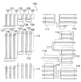
図1は、複数のIC形状を含むICパターン100を描写している。例示されているものは、チップ設計全体のうちの小さいエリア、たとえば、数ミクロン(μm)四方のエリアである。この図では、実線はポリシリコン導体(「PC:polysiliconconductor」)を表し、破線は拡散エリア(diffusion area)を表す。図1には、10個の拡散エリア110、111、112、113、114、115、116、117、118、119が例示されている。拡散エリア110、111、112、113、114、115、116、117、118、119を横切るPC線120、121、122、123、124、125、126は、CMOS電界効果トランジスタ(FET:fieldeffect transistor)用などのゲートとして機能する。ゲートは、エッジ・ベースのイメージ転写プロセスによって形成しなければならず、したがって、同じ最小厚さ、たとえば、50nm(500Å)を有することになる。拡散エリアの外側のPC線は相互接続として機能する。PC線127は、PC線120、121、122の底部を接続する。PC線127などの相互接続は、典型的には、より太くなり、寸法変化に対してあまり敏感ではないことに留意されたい。したがって、相互接続であるPC線127は、エッジ・ベースのイメージ転写の代わりに、光リソグラフィによって適切に形成されるであろう。135および136など、図1に図示されているいくつかの最小厚さのPC線は、拡散エリア113を越えて延び、それにより、IC形成中の潜在的なミスアライメントにもかかわらず、135、136が拡散エリア113を横切ることを保証する。
FIG. 1 depicts an
好ましい実施形態の目標は、可能な限り多くのオーバラップを有し、BLOCKおよびLITHO用のSITまたは位相シフト(alternating phase shift)・マスクなどのエッジ・ベースのイメージ転写プロセスの使用により集積回路を形成するために1組のマスク・セットを生成することにある。マスクを生成するプロセスは、まず、SITによって形成しなければならないすべてのPC線を検出することと、次に、BLOCKマスクを使用して特定の断片を消去することと、次に、SITによって形成することができない線をLITHOを使用して追加することを含む。「オーバラップ」とは、処理許容度により、様々な断片がギャップなしでまとまることを意味する。たとえば、「オーバラップ」により、クリティカル(critical)PC線(たとえば、線125の下端部)がノンクリティカル(non-critical)PC線(たとえば、129)に接続される場合にLITHOパターンがSITパターンにオーバラップしなければならないことを意味する。オーバラップすることにより、接続が保証される。最終的に、様々な断片を連続的で製造可能な1つのパターンにまとめる(assemble)ことが望ましい。図1は、エッジ・ベースのイメージ・プロセスの利点を可能な限り利用しながら(すなわち、可能な限りLITHOを使用せず)、図1に表された物理的な集積回路レイアウトを実現するために必要な様々なマスクを生成する努力の最終目標を表している。 The goal of the preferred embodiment is to have as much overlap as possible and form an integrated circuit by using an edge-based image transfer process such as SIT for BLOCK and LITHO or an alternating phase shift mask To create a set of masks to do this. The process of generating a mask first detects all PC lines that must be formed by SIT, then erases a specific fragment using a BLOCK mask, and then forms by SIT. Including adding lines that cannot be done using LITHO. “Overlap” means that various pieces are grouped without gaps, depending on processing tolerance. For example, an “overlap” causes a LITHO pattern to become a SIT pattern when a critical PC line (eg, the lower end of line 125) is connected to a non-critical PC line (eg, 129). Means that they must overlap. By overlapping, the connection is guaranteed. Finally, it is desirable to assemble the various pieces into a continuous and manufacturable pattern. FIG. 1 illustrates the physical integrated circuit layout depicted in FIG. 1 while utilizing the advantages of edge-based image processing as much as possible (ie, using LITHO wherever possible). It represents the end goal of the effort to generate the various masks needed.
図2は、本発明によりクリティカルおよびノンクリティカル中心線ICセグメントに分割された図1のICパターン内の各IC形状を描写している。PCセグメントは、「クリティカル」または「ノンクリティカル」のいずれかとして定義され分類される。最小厚さを有するゲートになるクリティカル中心線セグメントは実線(solid)で図示されている。ノンクリティカル中心線セグメントは影付き(shaded)で図示されている。たとえば、クリティカル中心線セグメント220、221、222、223、224、225、226は、PC線120、121、122、123、124、125、126にそれぞれ対応する。ノンクリティカル中心線セグメント137、138、139は、PC線127、128、129にそれぞれ対応する。本明細書で上述した通り、クリティカル・セグメントはエッジ・ベースのイメージ転写プロセスによって形成しなければならず、ノンクリティカル・セグメントはエッジ・ベースのイメージ転写プロセスによる形成に制限されない。しかし、好ましい実施形態によりエッジ・ベースのイメージ転写プロセスを最適化するために、エッジ・ベースのイメージ転写プロセスを使用して、可能な限り多くのノンクリティカルPCセグメントを形成することが望ましい。PCセグメント(たとえば、130・・・139)はいずれも、500Åなど、目標となるエッジ・ベースのイメージ転写の厚さである厚さで描かれている。エッジ・ベースのイメージ転写は、500Åなど、1つの狭い構造体サイズしか生み出さない。したがって、非最小チャネル長ゲート、または換言すれば、たとえば500Åより太いチャネル長ゲートは、中心線生成から明確に排除される。というのは、このような構造体は従来のリソグラフィ手段によってパターン形成しなければならないからである。
FIG. 2 depicts each IC shape in the IC pattern of FIG. 1 divided into critical and non-critical centerline IC segments according to the present invention. PC segments are defined and classified as either “critical” or “non-critical”. The critical centerline segment that results in the gate having the minimum thickness is shown as a solid line. Non-critical centerline segments are shown shaded. For example,
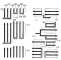
図3は、中心線を作成するための図2に図示されているクリティカルおよびノンクリティカル中心線ICセグメントの併合(merger)を描写している。たとえば、クリティカル中心線セグメント220、221、222とノンクリティカル中心線セグメント227はIC形状310に併合され、クリティカル中心線セグメント223、224とノンクリティカル中心線セグメント228はIC形状311に併合され、クリティカル中心線セグメント225、226とノンクリティカル中心線セグメント229はIC形状312に併合される。各クリティカル中心線セグメントごとに、併合断片(mergingpiece)は必ずノンクリティカルになる。図3の併合断片は227、228、および229である。図3に図示されているクリティカル・セグメントとノンクリティカル・セグメントの併合は、エッジ・ベースのイメージ転写マスクを使用して完全に形成された場合のICパターンを表している。しかし、エッジ・ベースのイメージ転写マスクを使用してすべてのIC形状を形成できるわけではなく、したがって、何らかのIC形状はリソグラフィで形成しなければならない。図3は、U字形311、312、T字形、E字形、くし形、L字形、直線形、およびO字形などの様々なIC形状を描写しており、そのうちのいくつかはエッジ・ベースのイメージ転写マスクで作成することができ、いくつかは作成することができない。U字形IC形状はエッジ・ベースのイメージ転写マスクで作成することができ、T字形IC形状は作成することができない。ICパターンのその他のセグメントはエッジ・ベースのイメージ転写マスクによって形成することができない。図3に図示されている通り、併合されたセグメントのいくつかは、線の端部から延びる小さい「こぶ(nub)」または「テール(tail)」などの付加物(appendage)を有する。このような付加物は、エッジ・ベースのイメージ転写プロセスの解像度以下のものであるので、エッジ・ベースのイメージ転写マスクを使用して形成することができず、リソグラフィで形成されることになる。
FIG. 3 depicts a merger of the critical and non-critical centerline IC segments illustrated in FIG. 2 for creating a centerline. For example,
図4は、図3の併合時に検出された付加物のクリーンアップを描写している。図3に図示されている「こぶ」および「テール」はすべて除去される。除去された付加物に関するデータは、後で処理するために保管される。たとえば、O字形上の「テール」は、除去され、リソグラフィによって後で設計に挿入するために保管される。付加物のクリーンアップは、エッジ・ベースのイメージ転写によって形成しなければならないIC形状については実行することができない。換言すれば、クリティカル構造体は一切除去することができない。ICに関する設計規則では、必須のエッジ・ベースのイメージ転写構造体が付加物を有することを禁止しているはずである。 FIG. 4 depicts the adduct cleanup detected during the merge of FIG. All of the “humps” and “tails” illustrated in FIG. 3 are removed. Data regarding the removed adduct is stored for later processing. For example, the “tail” on the O-shape is removed and stored for later insertion into the design by lithography. Adduct cleanup cannot be performed for IC shapes that must be formed by edge-based image transfer. In other words, no critical structures can be removed. Design rules for ICs should prohibit essential edge-based image transfer structures from having appendages.
図5は、併合されたがクリーンアップされた図4のIC形状全体に関するエッジ・ベースのイメージ転写マスク形状を描写している。図5では、すべての中心線形状の片側に1つずつ、エッジ・ベースのイメージ転写形状が生成されている。エッジ・ベースのイメージ形状は陰影線(hatched line)によって表されている。エッジ・ベースのイメージ転写形状はSITまたは位相シフト(alternating phase shift)・マスクを介して作成することができるが、好ましい実施形態の説明のために、本明細書ではエッジ・ベースのイメージ転写プロセスとしてSITについて論じることにする。SIT形状510は、U字形構造体の内側またはO字形511の内側/外側に形成することができる。SIT形状がO字形の内側/外側のいずれに形成されるかという選択については、図13に関して本明細書で後述することにする。IC形状520は意味ありげにT字形を組み込んでいるが、上述の通り、T字形IC形状はエッジ・ベースのイメージ転写プロセスで形成することができない。このようなエラーについては、図6に関してさらに詳述することにする。
FIG. 5 depicts an edge-based image transfer mask shape for the entire IC shape of FIG. 4 that has been merged but cleaned up. In FIG. 5, one edge-based image transfer shape is generated, one on each side of all centerline shapes. Edge-based image shapes are represented by shaded lines. Edge-based image transfer shapes can be created via SIT or an alternating phase shift mask, but for purposes of describing the preferred embodiment, the present specification provides an edge-based image transfer process. Let's discuss SIT. The
図6は、図5に描写されているICパターン全体に関するエッジ・ベースのイメージ転写マスク形状の使用時のエラーを描写している。エラーは黒い実線(solid black line)によって描写されている。上述の通り、SITはT字形を形成することができず、したがって、図5に描写されているT字形520は黒い実線を有する。図7に関してさらに詳述するように、T字形IC形状などの中心線表現の部分は、その後、選択的に除去される。PCを付着させるための空間がメサ間に存在しない恐れがあるので、T字形に加えて、隣接するIC対形状は形成することができない。これは、2本の黒い実線を有する2つのE字形パターンと2本の実線を有するくし形パターンの両方で図6に描写されている。この問題を解消するために、すべての隣接するSIT対形状にバイナリ・プロパティ(binaryproperty)が割り当てられ、対に含まれる他のすべてのIC形状のみがSITによって形成される。SIT形状は線の形成のために可能なものではないので、T字形および隣接するIC対形状に加えて、エラーが発生する可能性がある。これは、右上隅および右下隅のIC形状内の実線によって図6に描写されている。エラーが識別されると、図7に描写される改訂された1組の中心線セットが生成される。
FIG. 6 depicts errors when using an edge-based image transfer mask geometry for the entire IC pattern depicted in FIG. Errors are depicted by a solid black line. As mentioned above, SIT cannot form a T-shape, and therefore the T-
図7は、図6で検出されたエラーに基づくICパターンのセグメントに関するエッジ・ベースのイメージ転写マスク形状の精選除去(select elimination)を描写している。図5のエラーに関連するICパターンは、SITによって形成されたIC形状のセットから排除される。加えて、相互接続など、最小値より広いセグメントを有するいくつかのIC形状は、このようなIC形状がエラーに関連していた場合、SITによって形成されたIC形状のセットから排除されることになる。しかし、最小値より広いセグメントを有するIC形状がすべて排除されるわけではない。相互接続710および711は、最小値より広いセグメントであるが、図7に描写されている精選除去で排除されていないことに留意されたい。これは、セグメント710および711が図5のエラーを有するIC形状として識別されなかったからである。
FIG. 7 depicts the selective elimination of the edge-based image transfer mask shape for a segment of the IC pattern based on the error detected in FIG. The IC pattern associated with the error of FIG. 5 is excluded from the set of IC shapes formed by the SIT. In addition, some IC shapes that have wider segments than the minimum, such as interconnects, will be excluded from the set of IC shapes formed by SIT if such IC shapes are associated with errors. Become. However, not all IC shapes having segments wider than the minimum value are excluded. Note that interconnects 710 and 711 are segments that are wider than the minimum value, but have not been eliminated by the selective removal depicted in FIG. This is because
図8は、図7の精選除去に基づいて改良されたエッジ・ベースのイメージ転写マスク形状を描写している。図8では、E字形およびくし形IC形状にバイナリ・プロパティが関連付けられているので、SITは2本の可能な中心線のうちの1本のみに形成されることに留意されたい。 FIG. 8 depicts an improved edge-based image transfer mask shape based on the selective removal of FIG. Note that in FIG. 8, the SIT is formed on only one of the two possible centerlines since the binary properties are associated with the E-shaped and comb IC shapes.
図9は、図8の改良されたエッジ・ベースのイメージ転写マスク形状におけるエラーを描写している。図9では、図6のようなエラーが黒い実線(solid black)で描写されている。右上のIC形状には、この場合も隣接するSIT形状とともに中心線が存在する。このパターンの両側にメサが存在しなければならないと思われるので、エラーが描写されている。加えて、図9は、本明細書で上述した通り、SITによって形成できないT字形も描写している。 FIG. 9 depicts errors in the improved edge-based image transfer mask shape of FIG. In FIG. 9, the error as shown in FIG. 6 is depicted by a solid black line. In the upper right IC shape, there is also a center line together with the adjacent SIT shape. The error is depicted because it appears that there must be mesas on both sides of the pattern. In addition, FIG. 9 also depicts a T-shape that cannot be formed by SIT as described herein above.
図10は、図9のICパターンのセグメントに関するエッジ・ベースのイメージ転写マスク形状の追加の精選除去(further select elimination)を描写している。図9のエラーに関連するIC形状の場合、図10では、非ゲート形成領域内の狭いセグメントが除去されている。図6のエラーに関連するIC形状と比較すると、図7では、最小セグメントより広いものが除去されていた。図10の精選除去の結果として、図9で黒い実線であった中心線セグメントがSITなしで描写されている。したがって、図10は、「T字形」全体が除去されていることを描写している。このように2回改訂された中心線に基づいて、次に、PC線を形成するためにどこにSIT形状を形成できるかが判断される。 FIG. 10 depicts additional further select elimination of the edge-based image transfer mask shape for the IC pattern segments of FIG. In the case of the IC shape associated with the error of FIG. 9, in FIG. 10, a narrow segment in the non-gate formation region has been removed. Compared to the IC shape associated with the error of FIG. 6, in FIG. 7, the area wider than the smallest segment was removed. As a result of the selective removal of FIG. 10, the center line segment, which was a black solid line in FIG. 9, is depicted without SIT. Thus, FIG. 10 depicts that the entire “T-shape” has been removed. Based on the centerline thus revised twice, it is next determined where the SIT shape can be formed to form the PC line.
図11は、図10の追加の精選除去に基づいてエッジ・ベースのイメージ転写マスク形状を作成する際の第1のステップを描写している。図11では、図10からの2回改訂された中心線セット内の中心線の両側にSIT形状が形成されている。最終的に、SITマスクを生成するために、2つのSIT形状のうちの1つだけが使用されることになる。たとえば、O字形に関しては、O字形の内側およびO字形の外側にSIT形状が存在する。最終的に、SITマスクを生成するために、2つのSIT形状のうちの1つだけが使用されることになる。同様に、図11の左上隅のU字形に関しては、両方のU字形の内側および外側にSIT形状が存在する。 FIG. 11 depicts the first step in creating an edge-based image transfer mask shape based on the additional selective removal of FIG. In FIG. 11, SIT shapes are formed on both sides of the center line in the center line set revised twice from FIG. Eventually, only one of the two SIT shapes will be used to generate the SIT mask. For example, regarding the O-shape, there are SIT shapes inside the O-shape and outside the O-shape. Eventually, only one of the two SIT shapes will be used to generate the SIT mask. Similarly, for the U-shape in the upper left corner of FIG. 11, there are SIT shapes inside and outside both U-shapes.
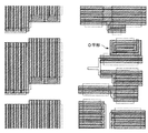
図12は、図11のエッジ・ベースのイメージ転写マスク形状前駆体(precursor)の半分の除去を描写している。SIT形状の半分だけが保持されている。O字形に関しては、外側のSIT形状が保持されていた。図12の左上隅のU字形に関しては、内側のSIT形状が保持されていた。 FIG. 12 depicts the removal of half of the edge-based image transfer mask shape precursor of FIG. Only half of the SIT shape is retained. Regarding the O-shape, the outer SIT shape was retained. As for the U-shape at the upper left corner of FIG. 12, the inner SIT shape was maintained.
図13は、図12の特定のセグメント形状に関するエッジ・ベースのイメージ転写マスク形状の精選選択(select choice)を描写している。このような選択は複雑度(complexity)に基づくものである。たとえば、複雑度は、SIT形状の隅をカウントすることによって測定することができる。たとえば、SIT形状内の隅が多いほど、SIT形状の複雑度が増す。代わって、SIT形状の外周とSIT形状の面積とを比較することによって複雑度を測定することができ、その場合、比率が低いほど複雑度が低下する。これは、O字形に関して図13に描写されている。O字形の外周に沿って、O字形内にメサを作成することは、あまり複雑ではないであろう。 FIG. 13 depicts a selection choice of edge-based image transfer mask shape for the particular segment shape of FIG. Such a selection is based on complexity. For example, complexity can be measured by counting the corners of the SIT shape. For example, the more corners in the SIT shape, the greater the complexity of the SIT shape. Instead, the complexity can be measured by comparing the outer periphery of the SIT shape and the area of the SIT shape, in which case the lower the ratio, the lower the complexity. This is depicted in FIG. 13 for an O-shape. Creating a mesa in the O shape along the outer periphery of the O shape would not be very complicated.
図14は、図13で行われた選択によるエッジ・ベースのイメージ転写マスク形状を描写している。SIT形状のうちのいくつかは反転(flip)されている。たとえば、O字形に関するSIT形状は、図12に描写されているO字形の外側から、図14に図示されているO字形の内側に反転されている。同様に、左上隅のE字形構造の中央のピン(middleprong)は、図12の中央のピンの左側から、図14の中央のピンの右側に反転されている。これは、図13で留意された複雑度を最小限にするために行われたものである。 FIG. 14 depicts an edge-based image transfer mask shape from the selection made in FIG. Some of the SIT shapes are flipped. For example, the SIT shape for the O-shape is inverted from the outside of the O-shape depicted in FIG. 12 to the inside of the O-shape depicted in FIG. Similarly, the middle pin of the E-shaped structure in the upper left corner is inverted from the left side of the central pin in FIG. 12 to the right side of the central pin in FIG. This was done to minimize the complexity noted in FIG.
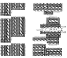
図15は、図14のエッジ・ベースのイメージ転写マスク形状に関するエッジ・ベースのイメージ転写排除エリアを描写している。詳細には、図15では、イメージ劣化を引き起こさずに、SITがそれを横切って形成する排除領域を拡張または併合することができない。このような領域は、この図ではダブル・ハッチング(double hatching)(X)で図示されている。このように実行する際に、SIT形状(メサ)間に少なくとも最小限の間隔が維持される。また、2つのSIT形状(たとえば、1511、1512)間の空間は、この図の丸で囲まれたエリアによって強調表示されているように、大きくなりすぎる場合もある。 FIG. 15 depicts an edge-based image transfer exclusion area for the edge-based image transfer mask shape of FIG. Specifically, in FIG. 15, the exclusion zone that the SIT forms across it cannot be expanded or merged without causing image degradation. Such a region is illustrated in this figure by double hatching (X). In doing so, at least a minimum spacing is maintained between SIT shapes (mesas). Also, the space between two SIT shapes (eg, 1511, 1512) may become too large, as highlighted by the circled area in this figure.
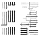
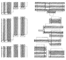
図16は、最終的なエッジ・ベースのイメージ転写マスク形状を描写している。最終的なエッジ・ベースのイメージ転写マスク形状は、図15によって画定された排除領域に基づくものである。図16にはSIT用のメサが描写されている。 FIG. 16 depicts the final edge-based image transfer mask shape. The final edge-based image transfer mask shape is based on the exclusion region defined by FIG. In FIG. 16, a mesa for SIT is depicted.
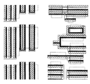
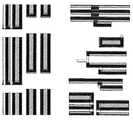
図17は、ブロック・マスクを描写している。ブロック・マスクは、SITの残余部分を除去し、意図されたSITイメージを保護する。たとえば、図17では、ブロック・マスクは、図17の右上隅に図示されているIC形状内のSITの部分を除去する。これは、このIC形状内の濃いラテラル・クロスハッチ(lateral cross hatch)によって図示されている。同様に、ブロック・マスクは意図されたSITイメージを保護し、これは、図17のO字形の外周を囲むクロス・ハッチによって図示されている。 FIG. 17 depicts a block mask. The block mask removes the remainder of the SIT and protects the intended SIT image. For example, in FIG. 17, the block mask removes the portion of the SIT in the IC shape shown in the upper right corner of FIG. This is illustrated by the dark lateral cross hatch within this IC shape. Similarly, the block mask protects the intended SIT image, which is illustrated by a cross hatch surrounding the O-shaped perimeter of FIG.
図18は、リソグラフィ・マスクを描写している。リソグラフィ・マスクを画定する際に、まず、SITによって生成しなければならないIC形状がリソグラフィ・マスクから排除される。上述の通り、ゲートはSITによって生成しなければならない。これが行われると、従来のリソグラフィによって形成しなければならないIC形状が画定される。上述の通り、T字形構造はリソグラフィによって形成しなければならない。ICパターンのうちのいくつかのエリアは冗長なものになり、換言すれば、SITとリソグラフィの両方で形成されることになる。上述の通り、このような冗長性またはオーバラップは、クリティカル線とノンクリティカル線との間に接続が行われることを保証するものである。図18では、冗長エリアのいくつかを丸で囲んでいる。 FIG. 18 depicts a lithographic mask. In defining a lithographic mask, first, IC shapes that must be generated by SIT are excluded from the lithographic mask. As mentioned above, the gate must be generated by SIT. When this is done, the IC shape that must be formed by conventional lithography is defined. As described above, the T-shaped structure must be formed by lithography. Some areas of the IC pattern are redundant, in other words, formed by both SIT and lithography. As described above, such redundancy or overlap ensures that a connection is made between a critical line and a non-critical line. In FIG. 18, some of the redundant areas are circled.
図19は、図16〜図18のマスクに基づいて予測されたエッジ・ベースのイメージ転写ウェハ・パターンを描写している。このように実行する際に、ICパターン内で追加のエラーが識別される可能性がある。 FIG. 19 depicts an edge-based image transfer wafer pattern predicted based on the masks of FIGS. In doing so, additional errors may be identified in the IC pattern.
図20は、エッジ・ベースのイメージ転写とリソグラフィとのオーバラップに基づく集積回路パターンを描写している。SITイメージは黒い実線で図示され、リソグラフィ・オーバラップはグレーで図示されている。 FIG. 20 depicts an integrated circuit pattern based on overlapping edge-based image transfer and lithography. The SIT image is illustrated by a solid black line, and the lithography overlap is illustrated in gray.
好ましい実施形態のレイアウト変換プロセスは、電子計算機支援設計システム上で実行されるソフトウェアとして実現することができる。このようなシステムは、当技術分野では周知のものであり、したがって、概略のみ説明することにする。 The layout conversion process of the preferred embodiment can be realized as software executed on an electronic computer aided design system. Such systems are well known in the art and will therefore only be outlined.
電子回路を設計するための現在のコンピュータ支援設計(CAD:computer aided design)システムは、ECADまたは電子CADシステムと呼ばれ、図形表示装置を備えたデジタル・コンピュータ上で実行される1組のソフトウェア・ツールをユーザに提供することによって、電子回路の設計を支援する。典型的には、ECADシステム上では、回路図エディタ(schematiceditor)、論理コンパイラ(logic compiler)、論理シミュレータ(logic simulator)、論理ベリファイヤ(logicverifier)、およびレイアウト・プログラム(layout program)という5つの主要ソフトウェア・プログラム機能が実行される。回路図エディタ・プログラムは、システムのユーザが、ディスプレイ画面を使用して回路図の入力または変更あるいはその両方を行えるようにし、プロセス内でネット・リスト(netlist)(コンポーネント間の接続の要約)を生成する。論理コンパイラは、ネット・リストを入力として受け取り、コンポーネント・データベースを使用して、レイアウト、検証、およびシミュレーションに必要な情報のすべてを1つまたは複数の回路図オブジェクト・ファイルに入れ、そのファイルのフォーマット(複数も可)はこれらの機能のために具体的に最適化される。論理ベリファイヤは、まとめて接続された複数の出力、過負荷の信号経路などの設計エラーがないかどうか、回路図をチェックし、このような設計問題が存在する場合はエラー表示を生成する。論理シミュレータは、回路図オブジェクト・ファイル(複数も可)およびシミュレーション・モデルを受け取り、1組のシミュレーション結果を生成し、命令、初期条件、およびファイルまたはユーザ入力の形でそれに提供される入力信号値に基づいて動作する。レイアウト・プログラムは、それから半導体チップ(または回路基板)をレイアウトし生産することができるデータを生成する。 Current computer aided design (CAD) systems for designing electronic circuits, called ECAD or electronic CAD systems, are a set of software that runs on a digital computer with a graphic display. Assist electronic circuit design by providing tools to users. Typically, on an ECAD system, there are five main components: a schematic editor, a logic compiler, a logic simulator, a logic verifier, and a layout program. Software program functions are executed. The schematic editor program allows the system user to use the display screen to enter and / or modify the schematic and create a netlist (summary of connections between components) in the process. Generate. The logic compiler takes a net list as input and uses a component database to put all of the information required for layout, verification, and simulation into one or more schematic object files and the format of the file (Multiple) are specifically optimized for these functions. The logic verifier checks a circuit diagram for a design error such as a plurality of outputs connected together and an overload signal path, and generates an error display if such a design problem exists. The logic simulator receives a schematic object file (s) and a simulation model, generates a set of simulation results, and instructions, initial conditions, and input signal values provided to it in the form of a file or user input Operates based on. The layout program then generates data from which a semiconductor chip (or circuit board) can be laid out and produced.
図21は、本発明のレイアウト変換プログラムを実行するために適した、一般化され非常に簡略化されたECADシステム2100を示している。コンピュータ(CPU)2102は、システムの中心にあり、キーボード2104およびポインティング・デバイス(マウス)2106などの入力装置ならびにモニタ2108およびプリンタ2110などの出力装置とのインターフェースを取るための従来のハードウェアをすべて含む。大容量記憶装置2112は、コンピュータ2102とのインターフェースが取られ、たとえば、(i)本発明のレイアウト変換ソフトウェア、および(ii)それに関して本発明のレイアウト変換ソフトウェアが、本明細書で上述した通り、SITプロセスを実行するために必要な3つのマスクのためのパターンを生成することになる既存の回路レイアウトを含む。コンピュータ2102は、当然のことながら、ローカル・エリア・ネットワーク(LAN)、広域ネットワーク(WAN)、またはインターネットなどの適切なネットワーク2114を介して任意の数の他のコンピュータ、ワークステーションなどと通信することができる。
FIG. 21 shows a generalized and highly
使用する際に、単数または複数のユーザは、本発明のレイアウト変換ソフトウェアをロードし、それに関してレイアウト変換ソフトウェアが、本明細書で上述した通り、SITプロセスを実行するために必要な3つのマスクのためのパターンを生成することになる既存の回路レイアウトをロードし、所望の結果を達成するために必要に応じてプログラムと対話することになるであろう。その後、マスクに関する出力ファイルが生成され、SITプロセスを実現するために他のユーザに伝えられる。 In use, the user or users load the layout conversion software of the present invention for which the three masks required for the layout conversion software to perform the SIT process as described herein above. Will load existing circuit layouts that will generate patterns for and interact with the program as needed to achieve the desired results. An output file for the mask is then generated and communicated to other users to implement the SIT process.
本発明は、1台のコンピュータ・システムで集中方式で実現するか、種々のエレメントがいくつかの相互接続コンピュータ・システムにわたって分散されている分散方式で実現することができる。本明細書に記載した方法を実行するために適合されたものであれば、どのような類のコンピュータ・システムまたはその他の装置でも適している。ハードウェアとソフトウェアの典型的な組み合わせとしては、ロードされ実行されたときに、本明細書に記載した方法を実行するようにコンピュータ・システムを制御するコンピュータ・プログラムを備えた汎用コンピュータ・システムにすることができるであろう。また、本発明は、本明細書に記載した方法の実現を可能にするすべての特徴を含み、コンピュータ・システムにロードされたときに、このような方法を実行することができるコンピュータ・プログラムに組み込むこともできる。 The present invention can be implemented in a centralized manner with a single computer system or in a distributed manner in which the various elements are distributed across several interconnected computer systems. Any type of computer system or other apparatus suitable for carrying out the methods described herein is suitable. A typical combination of hardware and software is a general purpose computer system with a computer program that, when loaded and executed, controls the computer system to perform the methods described herein. Would be able to. The present invention also includes all features that enable the implementation of the methods described herein and is incorporated into a computer program that can execute such methods when loaded into a computer system. You can also.
これに関連して、コンピュータ・プログラム手段(computer program means)またはコンピュータ・プログラムは、直接または他の言語、コード、または表記への変換、または異なる物質的形式による複製のいずれか一方または両方の後、情報処理機能を有するシステムに特定の機能を実行させるための1組の命令を任意の言語、コード、または表記で表した任意の表現を意味する。 In this context, a computer program means or computer program is either directly or after conversion to another language, code or notation, or after duplication in different material forms or both It means an arbitrary expression that expresses a set of instructions for causing a system having an information processing function to execute a specific function in an arbitrary language, code, or notation.
要するに、本発明は、集積回路を作成するためにエッジ・ベースのイメージ転写プロセスの使用を最適化する最終マスク・セットの作成を可能にする。このように実行する際に、本発明は、エッジ・ベースのイメージ転写に関連する頻度倍増および厳密な寸法制御という利点を利用する。同時に、本発明は、エッジ・ベースのイメージ転写で作成できない集積回路形状を作成するとともに、エッジ・ベースのイメージ転写で作成しなければならない集積回路形状とリソグラフィによって作成される集積回路形状との接続を保証するために、リソグラフィを使用する。 In summary, the present invention allows the creation of a final mask set that optimizes the use of an edge-based image transfer process to create an integrated circuit. In doing so, the present invention takes advantage of the frequency doubling and strict dimensional control associated with edge-based image transfer. At the same time, the present invention creates integrated circuit shapes that cannot be created by edge-based image transfer, and the connection between integrated circuit shapes that must be created by edge-based image transfer and integrated circuit shapes created by lithography. Lithography is used to ensure
具体的な好ましい実施形態およびその他の代替実施形態に関連して本発明について詳細に説明してきたが、上記の説明を考慮すると、非常に多くの代替例、変更例、および変形例が当業者にとって明白になることは明らかである。したがって、特許請求の範囲は、本発明の真の範囲および精神に含まれる、このような代替例、変更例、および変形例のすべてを包含することが意図されている。 Although the present invention has been described in detail in connection with specific preferred embodiments and other alternative embodiments, numerous alternatives, modifications, and variations will occur to those skilled in the art in view of the above description. It will be obvious. Accordingly, the claims are intended to cover all such alternatives, modifications and variations that fall within the true scope and spirit of the present invention.
100:集積回路レイアウト
110、111、112、113、114、115、116、117、118、119:拡散エリア
120、121、122、123、124、125、126、127、128、129、130、131、132、133、134、135、136、137:ポリシリコン導体(PC)線
100: Integrated
Claims (6)
複数のIC形状を含むICパターン内O字形状のイメージ転写形状を形成するために、側壁イメージ転写によるエッジ・ベースのイメージ転写マスクを生成するステップと、
前記O字形状から延びる残余部分を除去し該O字形状を保護するブロック・マスクを生成するステップと、
前記ICパターン内の残りのIC形状及び残余部分を形成するためにリソグラフィ・マスクを生成するステップと
を含む、方法。 A method of converting an IC design into a plurality of masks that optimizes sidewall image transfer to form an integrated circuit (IC) and an edge-based pattern transfer process with a lithographic mask , comprising:
Generating an edge-based image transfer mask by sidewall image transfer to form an O-shaped image transfer shape in an IC pattern comprising a plurality of IC shapes;
Generating a block mask that removes residual portions extending from the O-shape and protects the O-shape ;
Generating a lithographic mask to form remaining IC shapes and residual portions in the IC pattern.
前記ICパターン内の前記O字形状のエッジ・ベースのイメージ転写形状のために、前記複数内でエッジ・ベースのイメージ転写形状セットを選択するステップ
をさらに含む、請求項1に記載の方法。 Generating the edge-based image transfer mask comprises:
The method of claim 1, further comprising selecting an edge-based image transfer shape set within the plurality for the O-shaped edge-based image transfer shape in the IC pattern.
をさらに含む、請求項2に記載の方法。 The method of claim 2, further comprising the step of iteratively reducing the set based on errors in the generation of the edge-based image transfer shape.
をさらに含む、請求項3に記載の方法。 Within the reduced set of edge-based image transfer shapes, the most favorable edge-based image transfer shape is selectively selected for each edge-based image transfer shape, thereby providing an edge-based image transfer shape. The method of claim 3, further comprising creating a final set of image transfer shapes.
エッジ・ベースのイメージ転写形状の前記最終セットの周りに排除エリアを画定し、エッジ・ベースのイメージ拡張に応じて少なくとも部分的なIC障害を引き起こす恐れがあるエッジ・ベースのイメージ転写形状の拡張を実質的に防止するステップ
をさらに含む、請求項4に記載の方法。 The step of selectively selecting comprises:
Define an exclusion area around the final set of edge-based image transfer shapes to extend the edge-based image transfer shapes that may cause at least partial IC failure in response to edge-based image expansion The method of claim 4, further comprising the step of substantially preventing.
Applications Claiming Priority (1)
| Application Number | Priority Date | Filing Date | Title |
|---|---|---|---|
| US11/164,076 US7346887B2 (en) | 2005-11-09 | 2005-11-09 | Method for fabricating integrated circuit features |
Publications (3)
| Publication Number | Publication Date |
|---|---|
| JP2007133395A JP2007133395A (en) | 2007-05-31 |
| JP2007133395A5 JP2007133395A5 (en) | 2008-12-18 |
| JP4299853B2 true JP4299853B2 (en) | 2009-07-22 |
Family
ID=38005232
Family Applications (1)
| Application Number | Title | Priority Date | Filing Date |
|---|---|---|---|
| JP2006294951A Expired - Fee Related JP4299853B2 (en) | 2005-11-09 | 2006-10-30 | Method and program for forming integrated circuit features |
Country Status (3)
| Country | Link |
|---|---|
| US (1) | US7346887B2 (en) |
| JP (1) | JP4299853B2 (en) |
| CN (1) | CN1963666B (en) |
Families Citing this family (6)
| Publication number | Priority date | Publication date | Assignee | Title |
|---|---|---|---|---|
| US20090004573A1 (en) * | 2007-06-29 | 2009-01-01 | Aton Thomas J | System and method for making photomasks |
| US7818711B2 (en) * | 2007-06-29 | 2010-10-19 | Texas Instruments Incorporated | System and method for making photomasks |
| JP4789158B2 (en) * | 2008-08-18 | 2011-10-12 | 株式会社東芝 | Semiconductor device manufacturing method and semiconductor device |
| US20100127331A1 (en) * | 2008-11-26 | 2010-05-27 | Albert Ratnakumar | Asymmetric metal-oxide-semiconductor transistors |
| US8455364B2 (en) * | 2009-11-06 | 2013-06-04 | International Business Machines Corporation | Sidewall image transfer using the lithographic stack as the mandrel |
| US8716133B2 (en) | 2012-08-23 | 2014-05-06 | International Business Machines Corporation | Three photomask sidewall image transfer method |
Family Cites Families (14)
| Publication number | Priority date | Publication date | Assignee | Title |
|---|---|---|---|---|
| US4919768A (en) * | 1989-09-22 | 1990-04-24 | Shipley Company Inc. | Electroplating process |
| US5342501A (en) * | 1989-11-21 | 1994-08-30 | Eric F. Harnden | Method for electroplating metal onto a non-conductive substrate treated with basic accelerating solutions for metal plating |
| US6576976B2 (en) * | 1997-01-03 | 2003-06-10 | Integrated Device Technology, Inc. | Semiconductor integrated circuit with an insulation structure having reduced permittivity |
| US6083275A (en) * | 1998-01-09 | 2000-07-04 | International Business Machines Corporation | Optimized phase shift design migration |
| AT405842B (en) * | 1998-06-19 | 1999-11-25 | Miba Gleitlager Ag | Process for applying a metallic coating to a polymer surface of a workpiece |
| US6440839B1 (en) * | 1999-08-18 | 2002-08-27 | Advanced Micro Devices, Inc. | Selective air gap insulation |
| TWI226103B (en) * | 2000-08-31 | 2005-01-01 | Georgia Tech Res Inst | Fabrication of semiconductor devices with air gaps for ultra low capacitance interconnections and methods of making same |
| US6660154B2 (en) * | 2000-10-25 | 2003-12-09 | Shipley Company, L.L.C. | Seed layer |
| US6653231B2 (en) * | 2001-03-28 | 2003-11-25 | Advanced Micro Devices, Inc. | Process for reducing the critical dimensions of integrated circuit device features |
| US6609245B2 (en) * | 2001-11-29 | 2003-08-19 | International Business Machines Corporation | Priority coloring for VLSI designs |
| US6713396B2 (en) * | 2002-04-29 | 2004-03-30 | Hewlett-Packard Development Company, L.P. | Method of fabricating high density sub-lithographic features on a substrate |
| JP2005533283A (en) * | 2002-07-12 | 2005-11-04 | ケイデンス デザイン システムズ インコーポレイテッド | Method and system for context specific mask writing |
| US6901576B2 (en) * | 2002-11-20 | 2005-05-31 | International Business Machines Corporation | Phase-width balanced alternating phase shift mask design |
| US7100134B2 (en) * | 2003-08-18 | 2006-08-29 | Aprio Technologies, Inc. | Method and platform for integrated physical verifications and manufacturing enhancements |
-
2005
- 2005-11-09 US US11/164,076 patent/US7346887B2/en not_active Expired - Fee Related
-
2006
- 2006-10-30 JP JP2006294951A patent/JP4299853B2/en not_active Expired - Fee Related
- 2006-10-31 CN CN2006101429433A patent/CN1963666B/en not_active Expired - Fee Related
Also Published As
| Publication number | Publication date |
|---|---|
| CN1963666A (en) | 2007-05-16 |
| CN1963666B (en) | 2010-05-12 |
| US20070106972A1 (en) | 2007-05-10 |
| US7346887B2 (en) | 2008-03-18 |
| JP2007133395A (en) | 2007-05-31 |
Similar Documents
| Publication | Publication Date | Title |
|---|---|---|
| US6516459B1 (en) | Integrated circuit design correction using fragment correspondence | |
| US7367009B2 (en) | Convergence technique for model-based optical and process correction | |
| Liebmann et al. | TCAD development for lithography resolution enhancement | |
| KR102368588B1 (en) | Semiconductor device with filler cell region, method of generating layout diagram and system for same | |
| US7503028B2 (en) | Multilayer OPC for design aware manufacturing | |
| CN111834362B (en) | Integrated circuit and method of manufacturing an integrated circuit | |
| US11763061B2 (en) | Method of making semiconductor device and semiconductor device | |
| US20100183961A1 (en) | Integrated circuit layout design | |
| JP4299853B2 (en) | Method and program for forming integrated circuit features | |
| US11983475B2 (en) | Method for manufacturing a cell having pins and semiconductor device based on same | |
| US11741288B2 (en) | Routing-resource-improving method of generating layout diagram, system for same and semiconductor device | |
| Liebmann | Resolution enhancement techniques in optical lithography: It's not just a mask problem | |
| US11763057B2 (en) | Critical dimension uniformity | |
| US6738958B2 (en) | Modifying a hierarchical representation of a circuit to process composite gates | |
| Kahng et al. | New graph bipartizations for double-exposure, bright field alternating phase-shift mask layout | |
| CN112736027A (en) | Integrated circuit with constrained metal line placement | |
| US6735752B2 (en) | Modifying a hierarchical representation of a circuit to process features created by interactions between cells | |
| US20230014110A1 (en) | Variable tracks and non-default rule routing | |
| KR102459558B1 (en) | Semiconductor device including buried conductive fingers and method of making the same | |
| JP5340534B2 (en) | Mask layout design method and program for integrated circuit, and mask layout optimization method for integrated circuit | |
| Kahng et al. | Revisiting the layout decomposition problem for double patterning lithography | |
| Pack et al. | Physical and timing verification of subwavelength-scale designs: I. lithography impact on MOSFETs | |
| JP2001013670A (en) | Proximity correction method and device | |
| US20230394216A1 (en) | Integrated circuit device and manufacturing method of the same | |
| Haffner et al. | Mastering double exposure process window aware OPC by means of virtual targets |
Legal Events
| Date | Code | Title | Description |
|---|---|---|---|
| A521 | Written amendment |
Free format text: JAPANESE INTERMEDIATE CODE: A523 Effective date: 20081031 |
|
| A621 | Written request for application examination |
Free format text: JAPANESE INTERMEDIATE CODE: A621 Effective date: 20081031 |
|
| A871 | Explanation of circumstances concerning accelerated examination |
Free format text: JAPANESE INTERMEDIATE CODE: A871 Effective date: 20081031 |
|
| A975 | Report on accelerated examination |
Free format text: JAPANESE INTERMEDIATE CODE: A971005 Effective date: 20081125 |
|
| A131 | Notification of reasons for refusal |
Free format text: JAPANESE INTERMEDIATE CODE: A131 Effective date: 20081216 |
|
| A521 | Written amendment |
Free format text: JAPANESE INTERMEDIATE CODE: A523 Effective date: 20090316 |
|
| TRDD | Decision of grant or rejection written | ||
| A01 | Written decision to grant a patent or to grant a registration (utility model) |
Free format text: JAPANESE INTERMEDIATE CODE: A01 Effective date: 20090414 |
|
| A01 | Written decision to grant a patent or to grant a registration (utility model) |
Free format text: JAPANESE INTERMEDIATE CODE: A01 |
|
| A61 | First payment of annual fees (during grant procedure) |
Free format text: JAPANESE INTERMEDIATE CODE: A61 Effective date: 20090417 |
|
| R150 | Certificate of patent or registration of utility model |
Free format text: JAPANESE INTERMEDIATE CODE: R150 |
|
| FPAY | Renewal fee payment (event date is renewal date of database) |
Free format text: PAYMENT UNTIL: 20120424 Year of fee payment: 3 |
|
| FPAY | Renewal fee payment (event date is renewal date of database) |
Free format text: PAYMENT UNTIL: 20120424 Year of fee payment: 3 |
|
| S111 | Request for change of ownership or part of ownership |
Free format text: JAPANESE INTERMEDIATE CODE: R313113 |
|
| FPAY | Renewal fee payment (event date is renewal date of database) |
Free format text: PAYMENT UNTIL: 20120424 Year of fee payment: 3 |
|
| R350 | Written notification of registration of transfer |
Free format text: JAPANESE INTERMEDIATE CODE: R350 |
|
| FPAY | Renewal fee payment (event date is renewal date of database) |
Free format text: PAYMENT UNTIL: 20120424 Year of fee payment: 3 |
|
| S202 | Request for registration of non-exclusive licence |
Free format text: JAPANESE INTERMEDIATE CODE: R315201 |
|
| FPAY | Renewal fee payment (event date is renewal date of database) |
Free format text: PAYMENT UNTIL: 20130424 Year of fee payment: 4 |
|
| R350 | Written notification of registration of transfer |
Free format text: JAPANESE INTERMEDIATE CODE: R350 |
|
| FPAY | Renewal fee payment (event date is renewal date of database) |
Free format text: PAYMENT UNTIL: 20130424 Year of fee payment: 4 |
|
| FPAY | Renewal fee payment (event date is renewal date of database) |
Free format text: PAYMENT UNTIL: 20140424 Year of fee payment: 5 |
|
| R250 | Receipt of annual fees |
Free format text: JAPANESE INTERMEDIATE CODE: R250 |
|
| R250 | Receipt of annual fees |
Free format text: JAPANESE INTERMEDIATE CODE: R250 |
|
| R250 | Receipt of annual fees |
Free format text: JAPANESE INTERMEDIATE CODE: R250 |
|
| LAPS | Cancellation because of no payment of annual fees |
