JP4298277B2 - Medical diagnostic equipment - Google Patents
Medical diagnostic equipment Download PDFInfo
- Publication number
- JP4298277B2 JP4298277B2 JP2002351447A JP2002351447A JP4298277B2 JP 4298277 B2 JP4298277 B2 JP 4298277B2 JP 2002351447 A JP2002351447 A JP 2002351447A JP 2002351447 A JP2002351447 A JP 2002351447A JP 4298277 B2 JP4298277 B2 JP 4298277B2
- Authority
- JP
- Japan
- Prior art keywords
- data set
- imaged
- subsequent
- operating parameter
- area
- Prior art date
- Legal status (The legal status is an assumption and is not a legal conclusion. Google has not performed a legal analysis and makes no representation as to the accuracy of the status listed.)
- Expired - Fee Related
Links
Images


Classifications
-
- A—HUMAN NECESSITIES
- A61—MEDICAL OR VETERINARY SCIENCE; HYGIENE
- A61B—DIAGNOSIS; SURGERY; IDENTIFICATION
- A61B5/00—Measuring for diagnostic purposes; Identification of persons
- A61B5/05—Detecting, measuring or recording for diagnosis by means of electric currents or magnetic fields; Measuring using microwaves or radio waves
- A61B5/055—Detecting, measuring or recording for diagnosis by means of electric currents or magnetic fields; Measuring using microwaves or radio waves involving electronic [EMR] or nuclear [NMR] magnetic resonance, e.g. magnetic resonance imaging
-
- A—HUMAN NECESSITIES
- A61—MEDICAL OR VETERINARY SCIENCE; HYGIENE
- A61B—DIAGNOSIS; SURGERY; IDENTIFICATION
- A61B5/00—Measuring for diagnostic purposes; Identification of persons
- A61B5/70—Means for positioning the patient in relation to the detecting, measuring or recording means
- A61B5/704—Tables
Description
【0001】
【発明の属する技術分野】
本発明は医療診断装置に関する。
【0002】
【従来の技術】
医療画像診断装置としては特に超音波装置、X線コンピュータトモグラフィ装置および磁気共鳴装置が用いられる。この場合、磁気共鳴技術は検査対象物の体内の像を得るための公知の技術である。磁気共鳴装置では、基本磁界システムによって作り出される基本静磁界に、勾配システムによって作り出され急速に切り替わる勾配磁界が重ねられる。さらに、磁気共鳴装置は磁気共鳴信号を発生させるために高周波信号を検査対象物内へ入射し、発生した磁気共鳴信号を受信し、その信号に基づいて磁気共鳴像を作成する高周波システムを含む。
【0003】
例えば、機能的磁気共鳴像形成の場合は、検査対象物の同一の撮像すべき領域から時間的順序でデータセットが取得される。この場合、時間的順序中に撮像すべき領域が磁気共鳴像装置に対して位置変化する結果である、データセット間の差異を検知しかつ修正するために相応のいくつかの方法が公知である。
【0004】
時間的に連続して取得されたデータセットから位置変化を求めるための一群の方法は、6つの運動パラメータ(3つのパラメータは並進を、残りの3つのパラメータは回転を表わす)を用いた3次元空間における任意の固体運動の記述に基づく。固体の一般的運動は、例えば一次のテイラー展開により比較すべき2つのデータセットのすべてのもしくは選択された像点を含めて線形化され、この線形化によって次にパラメータが例えば反復的方法を用いて決定される。
【0005】
データセットをベースとする位置変化検出を行うための別の方法群では、k空間で記述された第1のデータセットと、第1のデータセットの後に時間的に連続して作成された第2のデータセットとのすべてのもしくは選択された点が互いに比較される。これらの方法は2つのデータセット内に同一に設けられているデータ点を比較する際に2つのデータセットの撮像時点間には位置変化がみられるので、撮像すべき領域の並進及び/又は回転がデータ点の位相及び/又は大きさの変化に反映されるということに基づいている。このような別の群の方法の1例としてナビゲータエコー法が挙げられる。
【0006】
機能的磁気共鳴像形成に関する詳細およびこれに適用される位置変化の検出・修正方法は例えば別の文献に記載されている(例えば、非特許文献1参照)。
【0007】
さらに、時間的に連続して取得されたデータセットから位置変化を検出するために、固体をベースとする方法とは異なり、時間順序の経過における撮像すべき領域の変形も許容される方法も公知であり、この詳細は別の文献に記載されている(例えば、非特許文献2参照)。
【0008】
経過観察においては検査対象物の検査すべき領域を、医療診断装置による検査を連続してまた時間を置いて何度も行うことにより適正に撮像するのが通例である。この場合、検査は例えば、数時間もしくは数週間の時間的間隔で行われる。診断装置の操作者は、第1回目の検査の後に時間的に続けて行われる検査では手動入力により検査対象物を、撮像すべき像が検査対象物内での位置決めおよび像形成特性に関して第1回目の検査の場合とできるだけ一致するように診断装置内に位置決めし診断装置を調節することを試みる。この場合、手動調節であるのでまあまあの一致が達成されるにすぎない。さらに、一致の程度はそのつどの操作者に依存する。また、上述の手動調節は比較的時間がかかる。
【0009】
【非特許文献1】
S.Thesenら著「リアルタイムでの機能的磁気共鳴断層撮影法」エレクトロメディカ68巻、第1号、2000年発行、p45〜52
【非特許文献2】
J.Hajnalら著「医学的画像記録法」CRC出版、2001年発行、第13章「Dave Rueckert:非固体記録法.コンセプト、アルゴリズムおよび応用」
【0010】
【発明が解決しようとする課題】
本発明の課題は、特に経過観察の枠内において迅速な処置を可能にする改善された医療診断装置を提供することにある。
【0011】
【課題を解決するための手段】
この課題は、本発明によれば、検査対象物の撮像すべき領域が診断装置の撮像ボリューム内に横たわされる検査のために、診断装置の第1の作動パラメータセットにより、撮像すべき領域の第1のデータセットを取得し、第1の作動パラメータセットおよび第1のデータセットを記憶する手段、
撮像すべき領域が新たに撮像ボリューム内に横たわされる後続検査のために、
記憶されている第1の作動パラメータセットにより、撮像すべき領域の第1の後続データセットを取得し、記憶する手段、
検査と後続検査との間の撮像ボリュームに関する撮像すべき領域の位置変化を求めるために第1のデータセットと第1の後続データセットとを互いに比較する手段、
求められた位置変化に整合させられた記憶されている第1の作動パラメータセットにより、別の第1の後続データセットを取得する手段を備え、
求められた位置変化が前もって設定されている閾値と比較され、求められた位置変化が閾値を超えた場合に整合が行われることことによって解決される(請求項1)。
本発明によれば、検査対象物の撮像すべき領域が診断装置の撮像ボリューム内に横たわされる検査のために、診断装置の第1の作動パラメータセットにより、撮像すべき領域の第1のデータセットを取得し、第1の作動パラメータセットおよび第1のデータセットを記憶する手段、
撮像すべき領域が新たに撮像ボリューム内に横たわされる後続検査のために、
記憶されている第1の作動パラメータセットにより、撮像すべき領域の第1の後続データセットを取得し、記憶する手段、
検査と後続検査との間の撮像ボリュームに関する撮像すべき領域の位置変化を求めるために第1のデータセットと第1の後続データセットとを互いに比較する手段、
求められた位置変化に整合させられた記憶されている第1の作動パラメータセットにより、別の第1の後続データセットを取得する手段を備え、
検査では、第2の作動パラメータセットにより、撮像すべき領域の第2のデータセットが作成され、第2の作動パラメータセットおよび第2のデータセットが記憶され、後続検査では、記憶されている第2の作動パラメータセットにより、撮像すべき領域の第2の後続データセットが作成され、後続検査では、検査と後続検査の間の撮像ボリュームに関する撮像すべき領域の位置変化を求めるために第2のデータセットと第2の後続データセットとが互いに比較され、後続検査では、求められた位置変化に整合させられた記憶されている第2の作動パラメータセットにより、別の第2の後続データセットが取得される医療診断装置も提案される。
【0012】
さらにまた、この課題は、本発明によれば、検査対象物の撮像すべき領域が診断装置の撮像ボリューム内に横たわされる検査のために、診断装置の第1の作動パラメータセットにより、撮像すべき領域の第1のデータセットを取得し、第1の作動パラメータセットおよび第1のデータセットを記憶し、第2の作動パラメータセットにより、撮像すべき領域の少なくとも1つの第2のデータセットを作成し、第2の作動パラメータセットおよび第2のデータセットを記憶する手段、
撮像すべき領域が新たに撮像ボリューム内に横たわされる後続検査のために、記憶されている第1の作動パラメータセットにより、撮像すべき領域の第1の後続データセットを取得し、記憶する手段、
検査と後続検査との間の撮像ボリュームに関する撮像すべき領域の位置変化を求めるために第1のデータセットと第1の後続データセットとを互いに比較する手段、
求められた位置変化に整合させられた記憶されている第2の作動パラメータセットにより、第2の後続データセットを取得する手段を備え、
求められた位置変化が前もって設定されている閾値と比較され、求められた位置変化が閾値を超えた場合に整合が行われることによっても解決される(請求項2)。
本発明によれば、検査対象物の撮像すべき領域が診断装置の撮像ボリューム内に横たわされる検査のために、診断装置の第1の作動パラメータセットにより、撮像すべき領域の第1のデータセットを取得し、第1の作動パラメータセットおよび第1のデータセットを記憶し、第2の作動パラメータセットにより、撮像すべき領域の少なくとも1つの第2のデータセットを作成し、第2の作動パラメータセットおよび第2のデータセットを記憶する手段、
撮像すべき領域が新たに撮像ボリューム内に横たわされる後続検査のために、記憶されている第1の作動パラメータセットにより、撮像すべき領域の第1の後続データセットを取得し、記憶する手段、
検査と後続検査との間の撮像ボリュームに関する撮像すべき領域の位置変化を求めるために第1のデータセットと第1の後続データセットとを互いに比較する手段、
求められた位置変化に整合させられた記憶されている第2の作動パラメータセットにより、第2の後続データセットを取得する手段を備え、
検査では、第3の作動パラメータセットにより、撮像すべき領域の第3のデータセットが作成され、第3の作動パラメータセットおよび第3のデータセットが記憶され、後続検査では、検査と後続検査の間の撮像ボリュームに関する撮像すべき領域の位置変化を求めるために第2のデータセットと第2の後続データセットとが互いに比較され、後続検査では、求められた位置変化に整合させられた記憶されている第3の作動パラメータセットにより、第3の後続データセットが取得される医療診断装置も提案される。
整合は、後続検査において、整合させられた作動パラメータセットにより取得された後続データセットが、作動パラメータセットによる検査において作成されたデータセットと同一の撮像すべき領域を表すように行われる(請求項3)。
診断装置が磁気共鳴装置である(請求項4)。
【0013】
検査中および後続検査用の記憶されているこの作動パラメータセットの使用中に第1の作動パラメータセットを記憶することにより、2つの検査において撮像すべき領域から像が撮像される。これらの像は、一致する像形成特性により撮像され、それによりこの点に関して直接的に互いに比較可能である。この結果、後続検査中に検査の像に一致する像形成特性を持つ像を撮像する目的での診断装置の時間のかかる手動調節を後続検査では行わなくて済むようになる。
【0014】
また、検査に一致する後続検査において撮像ボリューム内に撮像すべき領域を横たわさせるために、記憶されている第1の作動パラメータセットが参照される。1つの実施態様では、検査対象物が先行の検査に一致する後続検査では診断装置の寝台装置上に横たわされる。患者にとってこれは、例えば患者が第1の作動パラメータセットに記憶されているデータに基づき仰臥位で頭を先にして横たわることを意味する。次に、第1の作動パラメータセットに記憶されているデータに基づいて、撮像ボリューム内で撮像すべき領域を位置決めするための寝台装置の移動が、例えば撮像すべき領域をマーキングするレーザバイザの下で自動的に中断なく行われる。
【0015】
別の実施態様では、患者は後続検査では寝台装置上に任意の体位で横たわされる。この場合、カメラ装置は患者の体位種類に関係して患者の輪郭を検出する。その結果、記憶されている第1の作動パラメータセットと関連させて寝台装置の移動が求められ、実施されるので、後続検査では撮像すべき領域が検査に関して同等の方法で撮像ボリューム内に位置決めされる。
【0016】
有利な実施態様において、後続検査では、検査と後続検査の間の撮像ボリュームに関する撮像すべき領域の位置変化を求めるために第1のデータセットと第1の後続データセットとが互いに比較される。位置変化がみられる場合、後続検査では、位置変化に関して相応に整合させられた第1の作動パラメータセットにより、別の第1の後続データセットが取得されるので、検査の像および後続検査の像は撮像すべき領域を示し、後続検査の像には、検査とは異なった位置決めが行われるので撮像すべき領域からずれた検査対象物領域は撮像されない。これによって、検査の像および後続検査の像は上述した像形成特性に関してだけでなく、検査対象物の撮像すべき領域に関しても直接的に互いに比較可能となる。これによって、像の比較可能性は最大となるので、例えば病変は病変として一義的に診断可能となる。
【0017】
【発明の実施の形態】
本発明の別の利点、特徴および詳細について以下に記述する実施例で図面に基づき説明する。
【0018】
図1は磁気共鳴装置の概略図を示している。この磁気共鳴装置は基本磁界を作り出すために基本磁界装置11を、勾配磁界を作り出すためには勾配コイル装置12を含む。そのほかに、磁気共鳴装置は、磁気共鳴信号を発生させるために高周波信号を検査対象物内へ入射可能でありまた発生した磁気共鳴信号を受信可能であるアンテナ装置14も含む。さらに、磁気共鳴装置は、検査対象物、例えば検査すべき患者19が横たわされる移動式寝台装置15をも含む。
【0019】
シーケンスに基づいて勾配コイル装置12内の電流を制御するために、勾配コイル装置12は中央制御装置16に接続されている。シーケンスに基づいて投射すべき高周波信号を制御しかつアンテナ装置14によって受信された磁気共鳴信号を記憶するために、アンテナ装置14も同様に中央制御装置16に接続されている。例えば、磁気共鳴装置の撮像ボリューム18内での撮像すべき領域である患者19の胸郭領域を中心にして位置決めされた寝台装置15の移動を制御するために、寝台装置15も同様に中央制御装置16に接続されている。中央制御装置16は表示・操作装置17と接続されており、この表示・操作装置を通じて操作者の入力、例えば所望のシーケンス型およびシーケンスパラメータが中央制御装置16へ供給される。そのほかに、表示・操作装置17には特に形成された磁気共鳴像が表示される。
【0020】
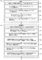
図2は本発明の実施例として、磁気共鳴装置の作動方法に関する第1フローチャートを示している。この第1フローチャートを説明するために、例として図1に示されている磁気共鳴装置を参照する。
【0021】
患者19の検査20の場合、第1ステップ21において例えば撮像すべき領域である患者19の胸郭領域が磁気共鳴装置の撮像ボリューム18内に横たわされる。このために、寝台装置15はその上に仰臥位で横たわされている患者19と共に相応に移動させられる。続いて、ステップ22において第1のデータセット、例えば撮像すべき領域の第1の層が撮像される。これには、特に磁気共鳴装置の操作者によって表示・操作装置17に入力されたデータ、すなわちシーケンス型、シーケンスパラメータ、FOV(Field of View;撮像視野)、解像度、第1の層の位置および方位などが纏められている第1の作動パラメータセットが用いられる。第1のデータセットをまとまったものとして入手することにより、第1のデータセットは第1の作動パラメータセットと共にステップ23において磁気共鳴装置の中央制御装置16に記憶される。この場合、第1のデータセットは必ずしも時間的に最初に撮像されたデータセットである必要はない。というのは、例えば第1のデータセットの前にスカウト(Scout)及び/又はその他の磁気共鳴撮像が先に行われているかもしれないからである。さらに、ステップ24において、第2のデータセット、例えば胸郭領域の第2の層が、第2の作動パラメータセットを用いて撮像される。この場合、ステップ25において第2のデータセットも所属の第2の作動パラメータセットと共に磁気共鳴装置の中央制御装置16に記憶される。
【0022】
上述したデータセットは、例えば胸郭領域の治療の計画および実施のために使用される。例えば、数日後に後続検査30の枠内での治療成果の検討のために患者19の胸郭領域が新たに磁気共鳴装置で検査されるとする。この場合、後続検査30では第1ステップ31において胸郭領域が新たに撮像ボリューム18内に載置される。この場合、患者19を寝台装置15上のどの位置に横たわすべきか、また患者19のどの領域を撮像すべき領域として撮像ボリューム18内に位置決めすべきかは、検査20の記憶されている第1の作動パラメータセットから取り出すことができる。この場合、先行の検査20と完全に同一の位置決めを行うことは、患者19を寝台装置15上にミリ単位の精確さで横たわすことができないことからしても無理である。
【0023】
撮像ボリューム18内に撮像すべき領域を位置決めした後に、ステップ32において記憶されている第1の作動パラメータセットを用いて第1の後続データセットが取得され、このデータセットは記憶されている第1の作動パラメータを用いているため、第1のデータセットと同一の像形成特性、すなわちコントラスト、解像度、FOVなどにより取得される。このことは、第1のデータセットと第1の後続データセットとを比較する診断医師にとって有用であるだけでなく、次のステップ33にとっても有用である。このステップ33においては、検査20と後続検査30との間で撮像ボリューム18に関する撮像すべき領域の場合によっては存在する位置変化を求めるために、第1のデータセットが第1の後続データセットと比較される。機能的磁気共鳴像形成の場合に適用される冒頭に挙げた方法をこれに用いることができる。この場合、場合によっては存在する位置変化を検出可能とするためには、第1のデータセットおよび第1の後続データセットが患者19の少なくとも1つの同一の部分領域を含む必要がある。そうでない場合には、この方法は表示・操作装置17への相応の通知を中断する。次に、操作者は撮像すべき領域の相応のより細かな位置決めを実施する必要がある。相応の中断および通知は、変形が設定可能な閾値を超える場合には、撮像すべき領域の変形を許容するような冒頭に挙げた方法においても生じる。
【0024】
ステップ33において、前もって設定されている閾値を超える位置変化が確認された場合は、次のステップ34において別の第1の後続データセットが取得され、この場合、そのために記憶されている第1の作動パラメータセットは、像形成特性に関してだけでなく、撮像すべき領域の位置に関しても検査20の第1のデータセットとの一致が達成されるように整合されて用いられる。
【0025】
表示・操作装置17において第1のデータセットおよび別の第1の後続データセットを表示する際、診断医師にとって2つの像が直接比較でき、検査20と後続検査30との間の変化を簡単に確認できる。というのは、像形成特性だけでなく、撮像された層も両者の像において同一だからである。
【0026】
別のステップ35〜37においては、ステップ32〜34に関して先に記述されたことが第2の作動パラメータセットに関しても同様に繰り返される。同様の繰返しは別の作動パラメータセットに関しても行うことができる。
【0027】
図2の第1フローチャートに基づく処置の場合には、データセット間ないしは後続データセット間で生じる位置変化も検出でき、比較できるという利点がある。これに対して、本発明の別の実施例である図3に基づく第2フローチャートの場合は、この種の位置変化はデータセットないしは後続データセットの遅滞ないし不正確によってのみ検出され、比較されるが、後続検査30´に関してはより短い測定時間が達成される利点がある。
【0028】
図3の第2フローチャートの場合は、検査20´の第1のステップ21´〜25´は、図2の第1フローチャートにおける検査20のステップ21〜25に相当する。しかし、第2フローチャートの場合、そのほかにステップ26´、27´において第3の作動パラメータセットにより第3のデータセットが取得され、この第3のデータセットは第3の作動パラメータセットと共に記憶される。
【0029】
図3の第2フローチャートにおける後続検査30´のステップ31´〜33´も図2の第1フローチャートのステップ31〜33と同一である。しかし、これに続いて、ステップ34´において、ステップ33´において求められた位置変化に整合させられた記憶されている第2の作動パラメータセットにより第2の後続データセットが取得される。時間節約の理由から、第1フローチャートのステップ34に基づく別の第1の後続データセットの取得は行われない。第2フローチャートの場合、第1の後続データセットの相応の整合のために場合によってはこのセットを遡及的に修正することができる。
【0030】
図3のフローチャートのステップ35´、36´においては、第3の作動パラメータセットに関してステップ33´〜34´で記述されたことが同様に繰り返される。別の作動パラメータセットに関する別の繰返しも同様に行うことができる。
【0031】
1つの実施例では、後続検査30、30´の別の時間的正確さは、位置変化の検出がただ1回だけ第1のデータセットおよび後続データセットにより実施されることにより達成可能となる。ただし、この結果、第1のデータセット及び/又は後続データセットの後に生じる位置変化は無視されたままになる。
後続検査30、30´に関して記述されたことは当然のことながら、別のいずれの後続検査にも同様に適用可能である。また、上述した方法は造影剤研究の場合にも適用可能であり、この場合投与方式、投与量、濃度および造影剤の時間的管理は作動パラメータセットに共に記憶され、したがって後続検査の際に同様に再現可能である。
【図面の簡単な説明】
【図1】磁気共鳴装置の概略図。
【図2】磁気共鳴装置の作動方法に関する第1フローチャート。
【図3】磁気共鳴装置の作動方法に関する第2フローチャート。
【符号の説明】
11 基本磁界装置
12 勾配コイル装置
14 アンテナ装置
15 寝台装置
16 中央制御装置
17 表示・操作装置
18 撮像ボリューム
19 患者[0001]
BACKGROUND OF THE INVENTION
The present invention relates to a medical diagnostic apparatus .
[0002]
[Prior art]
As the medical image diagnostic apparatus, an ultrasonic apparatus, an X-ray computer tomography apparatus, and a magnetic resonance apparatus are used. In this case, the magnetic resonance technique is a known technique for obtaining an in-vivo image of the inspection object. In a magnetic resonance apparatus, a basic static magnetic field created by a basic magnetic field system is superimposed on a gradient magnetic field created by a gradient system and rapidly switched. Further, the magnetic resonance apparatus includes a high frequency system that enters a high frequency signal into an object to be inspected to generate a magnetic resonance signal, receives the generated magnetic resonance signal, and creates a magnetic resonance image based on the signal.
[0003]
For example, in the case of functional magnetic resonance imaging, a data set is acquired in time order from the same region to be imaged of the inspection object. In this case, several corresponding methods are known for detecting and correcting differences between the data sets, which are the result of the position of the area to be imaged during the temporal sequence being changed relative to the magnetic resonance imaging device. .
[0004]
A group of methods for determining position changes from time-sequentially acquired data sets is three-dimensional using six motion parameters (three parameters represent translation and the remaining three parameters represent rotation). Based on the description of any solid motion in space. The general motion of the solid is linearized, including all or selected image points of two data sets to be compared, for example by a first order Taylor expansion, and this linearization then uses parameters such as iterative methods. Determined.
[0005]
In another method group for performing position change detection based on a data set, a first data set described in k-space and a second data created successively in time after the first data set. All or selected points with the current data set are compared with each other. In these methods, when comparing data points that are identically provided in the two data sets, a change in position is observed between the time points at which the two data sets are imaged. Therefore, translation and / or rotation of the area to be imaged is performed. Is reflected in changes in the phase and / or magnitude of the data points. One example of such another group of methods is the navigator echo method.
[0006]
Details regarding the functional magnetic resonance imaging and the position change detection / correction method applied thereto are described in, for example, another document (for example, see Non-Patent Document 1).
[0007]
Further, in order to detect a change in position from a data set acquired continuously in time, a method that allows deformation of a region to be imaged in the course of a time sequence is also known, unlike a solid-based method. The details are described in another document (for example, see Non-Patent Document 2).
[0008]
In the follow-up observation, it is usual that the region to be inspected of the inspection object is properly imaged by performing the inspection by the medical diagnostic apparatus continuously and repeatedly over time. In this case, the inspection is performed at time intervals of several hours or weeks, for example. The operator of the diagnostic apparatus performs the first inspection with respect to the position of the inspection object by manual input in the inspection performed in time, and the first image regarding the positioning and image forming characteristics of the image to be imaged in the inspection object. An attempt is made to position and adjust the diagnostic device in the diagnostic device so that it matches the case of the second examination as much as possible. In this case, since it is a manual adjustment, only a fair match is achieved. Furthermore, the degree of matching depends on the respective operator. The manual adjustment described above takes a relatively long time.
[0009]
[Non-Patent Document 1]
S. Thesen et al., “Functional Magnetic Resonance Tomography in Real Time”, Electro Medica Volume 68, No. 1, 2000, p45-52.
[Non-Patent Document 2]
J. et al. Hajnal et al., “Medical Image Recording,” CRC Publishing, 2001, Chapter 13 “Dave Rueckert: Non-Solid Recording. Concepts, Algorithms and Applications”
[0010]
[Problems to be solved by the invention]
An object of the present invention is to provide an improved medical diagnostic apparatus that enables rapid treatment, particularly within the framework of follow-up observation.
[0011]
[Means for Solving the Problems]
This problem is solved according to the present invention by the first operating parameter set of the diagnostic device for the examination in which the region to be imaged of the examination object lies in the imaging volume of the diagnostic device. Means for obtaining a first data set of the region and storing the first operating parameter set and the first data set;
For subsequent inspection where the area to be imaged is newly laid in the imaging volume,
Means for obtaining and storing a first subsequent data set of a region to be imaged according to a stored first operating parameter set;
Means for comparing the first data set and the first subsequent data set with each other in order to determine the position change of the area to be imaged with respect to the imaging volume between the examination and the subsequent examination;
Means for obtaining another first subsequent data set by means of a stored first operating parameter set matched to the determined position change;
The obtained position change is compared with a preset threshold value, and when the obtained position change exceeds the threshold value, matching is performed (claim 1).
According to the present invention , for the examination in which the area to be imaged of the inspection object is laid in the imaging volume of the diagnostic apparatus, the first operating parameter set of the diagnostic apparatus sets the first area to be imaged. Means for obtaining a data set of and storing a first operating parameter set and a first data set;
For subsequent inspection where the area to be imaged is newly laid in the imaging volume,
Means for obtaining and storing a first subsequent data set of a region to be imaged according to a stored first operating parameter set;
Means for comparing the first data set and the first subsequent data set with each other in order to determine the position change of the area to be imaged with respect to the imaging volume between the examination and the subsequent examination;
Means for obtaining another first subsequent data set by means of a stored first operating parameter set matched to the determined position change;
In the inspection, a second data set of the region to be imaged is created by the second operating parameter set, the second operating parameter set and the second data set are stored, and in the subsequent inspection, the stored second data set is stored. The second operating parameter set creates a second subsequent data set of the area to be imaged, and in the subsequent examination, a second to determine the position change of the area to be imaged with respect to the imaging volume between the examinations. The data set and the second subsequent data set are compared with each other, and in the subsequent examination, another second subsequent data set is obtained by means of a stored second operating parameter set aligned with the determined position change. Acquired medical diagnostic devices are also proposed.
[0012]
Furthermore, according to the present invention, this problem is achieved according to the first operating parameter set of the diagnostic device for an examination in which the region to be imaged of the examination object is lying in the imaging volume of the diagnostic device, A first data set of a region to be imaged is obtained, a first operating parameter set and a first data set are stored, and at least one second data of the region to be imaged is determined by the second operating parameter set. Means for creating a set and storing a second set of operating parameters and a second data set;
Acquire and store the first subsequent data set of the area to be imaged according to the stored first operating parameter set for subsequent examination where the area to be imaged is newly laid in the imaging volume Means to
Means for comparing the first data set and the first subsequent data set with each other in order to determine the position change of the area to be imaged with respect to the imaging volume between the examination and the subsequent examination;
Means for obtaining a second subsequent data set by means of a stored second operating parameter set aligned with the determined position change;
It is also solved by comparing the obtained position change with a preset threshold value and performing matching when the obtained position change exceeds the threshold value (Claim 2 ).
According to the present invention , for the examination in which the area to be imaged of the inspection object is laid in the imaging volume of the diagnostic apparatus, the first operating parameter set of the diagnostic apparatus sets the first area to be imaged. And a first operating parameter set and a first data set are stored, and a second operating parameter set is used to create at least one second data set of an area to be imaged. Means for storing a set of operating parameters and a second data set;
Acquire and store the first subsequent data set of the area to be imaged according to the stored first operating parameter set for subsequent examination where the area to be imaged is newly laid in the imaging volume Means to
Means for comparing the first data set and the first subsequent data set with each other in order to determine the position change of the area to be imaged with respect to the imaging volume between the examination and the subsequent examination;
Means for obtaining a second subsequent data set by means of a stored second operating parameter set aligned with the determined position change;
In the inspection, a third data set of an area to be imaged is created by the third operating parameter set, and the third operating parameter set and the third data set are stored. In the subsequent inspection, the inspection and the subsequent inspection The second data set and the second subsequent data set are compared with each other in order to determine the position change of the area to be imaged with respect to the imaging volume between them, and in the subsequent inspection, the stored data matched to the obtained position change is stored. A medical diagnostic device is also proposed in which a third subsequent data set is obtained with a third set of operating parameters .
The alignment is performed in a subsequent examination so that the subsequent data set acquired by the matched operating parameter set represents the same area to be imaged as the data set created in the inspection by the operating parameter set (claims). 3 ).
The diagnostic device is a magnetic resonance device (claim 4 ).
[0013]
By storing the first set of operating parameters during the examination and during use of this stored operating parameter set for subsequent examinations, images are taken from the areas to be imaged in the two examinations. These images are imaged with matching imaging properties, so that they can be directly compared with each other in this respect. As a result, time-consuming manual adjustment of the diagnostic apparatus for the purpose of capturing an image having an image forming characteristic that matches the image of the inspection during the subsequent inspection is not required in the subsequent inspection.
[0014]
Also, the stored first operating parameter set is referred to in order to lay down the area to be imaged in the imaging volume in a subsequent examination that matches the examination. In one embodiment, the test object is laid on a bed device of the diagnostic device in a subsequent test that matches the previous test. For the patient, this means, for example, that the patient lies head down first in a supine position based on data stored in the first set of operating parameters. Next, based on the data stored in the first operating parameter set, the movement of the couch device for positioning the area to be imaged in the imaging volume is, for example, under the laser visor marking the area to be imaged. Automatically done without interruption.
[0015]
In another embodiment, the patient is laid in any position on the couch device for subsequent examination. In this case, the camera device detects the contour of the patient in relation to the posture type of the patient. As a result, movement of the couch device is sought and carried out in relation to the stored first operating parameter set, so that in the subsequent examination, the area to be imaged is positioned in the imaging volume in an equivalent manner with respect to the examination. The
[0016]
In an advantageous embodiment, in the subsequent examination, the first data set and the first subsequent data set are compared with each other in order to determine the position change of the area to be imaged with respect to the imaging volume between examinations. If there is a change in position, the subsequent inspection obtains another first subsequent data set with the first operating parameter set correspondingly matched with respect to the position change, so that the inspection image and the subsequent inspection image are obtained. Indicates an area to be imaged, and the inspection object area deviated from the area to be imaged is not imaged in the image of the subsequent inspection because positioning different from the inspection is performed. As a result, the image of the inspection and the image of the subsequent inspection can be directly compared with each other not only with respect to the above-described image formation characteristics but also with respect to the region to be imaged of the inspection object. This maximizes image comparability, so that, for example, a lesion can be uniquely diagnosed as a lesion.
[0017]
DETAILED DESCRIPTION OF THE INVENTION
Further advantages, features and details of the invention will be described with reference to the drawings in the embodiments described below.
[0018]
FIG. 1 shows a schematic diagram of a magnetic resonance apparatus. The magnetic resonance apparatus includes a basic
[0019]
The
[0020]
FIG. 2 shows a first flowchart relating to an operation method of the magnetic resonance apparatus as an embodiment of the present invention. In order to explain this first flow chart, the magnetic resonance apparatus shown in FIG. 1 is referred to as an example.
[0021]
In the case of the
[0022]
The data set described above is used, for example, for planning and performing treatment of the thoracic region. For example, it is assumed that the thoracic region of the
[0023]
After positioning the area to be imaged in the
[0024]
In
[0025]
When displaying the first data set and another first subsequent data set on the display /
[0026]
In another step 35-37, what was described above for steps 32-34 is repeated for the second set of operating parameters as well. Similar iterations can be performed for other sets of operating parameters.
[0027]
In the case of the treatment based on the first flowchart of FIG. 2, there is an advantage that position changes occurring between data sets or subsequent data sets can be detected and compared. On the other hand, in the case of the second flow chart according to FIG. 3, which is another embodiment of the present invention, this kind of position change is detected and compared only by the delay or inaccuracy of the data set or the subsequent data set. However, there is an advantage that a shorter measurement time is achieved for the subsequent inspection 30 '.
[0028]
In the case of the second flowchart in FIG. 3, the
[0029]
[0030]
In steps 35 'and 36' of the flowchart of Fig. 3, what has been described in steps 33 'to 34' with respect to the third set of operating parameters is similarly repeated. Other iterations for different operating parameter sets can be performed as well.
[0031]
In one embodiment, another temporal accuracy of the
It will be appreciated that what has been described with respect to the
[Brief description of the drawings]
FIG. 1 is a schematic diagram of a magnetic resonance apparatus.
FIG. 2 is a first flowchart relating to an operation method of the magnetic resonance apparatus.
FIG. 3 is a second flowchart relating to an operation method of the magnetic resonance apparatus.
[Explanation of symbols]
DESCRIPTION OF
Claims (4)
撮像すべき領域が新たに撮像ボリューム内に横たわされる後続検査のために、記憶されている第1の作動パラメータセットにより、撮像すべき領域の第1の後続データセットを取得し、記憶する手段、
検査と後続検査との間の撮像ボリュームに関する撮像すべき領域の位置変化を求めるために第1のデータセットと第1の後続データセットとを互いに比較する手段、
求められた位置変化に整合させられた記憶されている第1の作動パラメータセットにより、別の第1の後続データセットを取得する手段を備え、
求められた位置変化が前もって設定されている閾値と比較され、求められた位置変化が閾値を超えた場合に整合が行われる
ことを特徴とする医療診断装置。For an examination in which the area to be imaged of the inspection object lies in the imaging volume of the diagnostic device, the first data set of the area to be imaged is acquired by the first operating parameter set of the diagnostic device. Means for storing a first operating parameter set and a first data set;
Acquire and store the first subsequent data set of the area to be imaged according to the stored first operating parameter set for subsequent examination where the area to be imaged is newly laid in the imaging volume Means to
Means for comparing the first data set and the first subsequent data set with each other in order to determine the position change of the area to be imaged with respect to the imaging volume between the examination and the subsequent examination;
Means for obtaining another first subsequent data set by means of a stored first operating parameter set matched to the determined position change;
A medical diagnostic apparatus characterized in that the obtained position change is compared with a preset threshold value, and matching is performed when the obtained position change exceeds the threshold value.
撮像すべき領域が新たに撮像ボリューム内に横たわされる後続検査のために、記憶されている第1の作動パラメータセットにより、撮像すべき領域の第1の後続データセットを取得し、記憶する手段、
検査と後続検査との間の撮像ボリュームに関する撮像すべき領域の位置変化を求めるために第1のデータセットと第1の後続データセットとを互いに比較する手段、
求められた位置変化に整合させられた記憶されている第2の作動パラメータセットにより、第2の後続データセットを取得する手段を備え、
求められた位置変化が前もって設定されている閾値と比較され、求められた位置変化が閾値を超えた場合に整合が行われる
ことを特徴とする医療診断装置。For an examination in which the area to be imaged of the inspection object lies in the imaging volume of the diagnostic device, the first data set of the area to be imaged is acquired by the first operating parameter set of the diagnostic device. , Storing the first operating parameter set and the first data set, creating at least one second data set of the region to be imaged by the second operating parameter set, Means for storing two data sets;
Acquire and store the first subsequent data set of the area to be imaged according to the stored first operating parameter set for subsequent examination where the area to be imaged is newly laid in the imaging volume Means to
Means for comparing the first data set and the first subsequent data set with each other in order to determine the position change of the area to be imaged with respect to the imaging volume between the examination and the subsequent examination;
Means for obtaining a second subsequent data set by means of a stored second operating parameter set aligned with the determined position change;
A medical diagnostic apparatus characterized in that the obtained position change is compared with a preset threshold value, and matching is performed when the obtained position change exceeds the threshold value.
Applications Claiming Priority (2)
| Application Number | Priority Date | Filing Date | Title |
|---|---|---|---|
| DE10160075.5 | 2001-12-07 | ||
| DE10160075A DE10160075B4 (en) | 2001-12-07 | 2001-12-07 | Method for operating an imaging medical diagnostic device |
Publications (3)
| Publication Number | Publication Date |
|---|---|
| JP2003180660A JP2003180660A (en) | 2003-07-02 |
| JP2003180660A5 JP2003180660A5 (en) | 2006-01-19 |
| JP4298277B2 true JP4298277B2 (en) | 2009-07-15 |
Family
ID=7708330
Family Applications (1)
| Application Number | Title | Priority Date | Filing Date |
|---|---|---|---|
| JP2002351447A Expired - Fee Related JP4298277B2 (en) | 2001-12-07 | 2002-12-03 | Medical diagnostic equipment |
Country Status (5)
| Country | Link |
|---|---|
| US (1) | US7610075B2 (en) |
| JP (1) | JP4298277B2 (en) |
| KR (1) | KR20030047790A (en) |
| CN (1) | CN1269452C (en) |
| DE (1) | DE10160075B4 (en) |
Families Citing this family (22)
| Publication number | Priority date | Publication date | Assignee | Title |
|---|---|---|---|---|
| US7627160B2 (en) * | 2003-06-13 | 2009-12-01 | General Electric Company | Analysis of temporal change using dual or multi-energy decomposition images |
| DE10357203B4 (en) | 2003-12-08 | 2018-09-20 | Siemens Healthcare Gmbh | Method and control device for operating a magnetic resonance tomography device and magnetic resonance tomography device |
| DE102004024097A1 (en) * | 2004-05-14 | 2005-12-08 | Siemens Ag | Method and apparatus for increasing patient safety in clinical scanners |
| US20060074295A1 (en) * | 2004-10-01 | 2006-04-06 | Nexgen | Combined MR coil technology in medical devices |
| DE102004058943B4 (en) * | 2004-12-07 | 2011-12-08 | Siemens Ag | Magnetic resonance system and method for checking the positioning of an examination object |
| DE102005026220A1 (en) * | 2005-06-07 | 2006-12-21 | Siemens Ag | Subject e.g. person, examination region`s e.g. spinal column, medical image data acquisition, analysis and representation performing method, involves displaying part of data set at display with graphical representation |
| DE102005029242B4 (en) * | 2005-06-23 | 2012-10-25 | Siemens Ag | Method for recording and evaluating image data of an examination object and associated device |
| DE102005029243A1 (en) * | 2005-06-23 | 2007-01-04 | Siemens Ag | Method for displaying and processing at least one examination image of an examination object |
| DE102005036515B4 (en) * | 2005-08-03 | 2015-07-09 | Siemens Aktiengesellschaft | Method for planning a study in a magnetic resonance system |
| DE102005044652B4 (en) * | 2005-09-19 | 2009-12-10 | Siemens Ag | Method for generating 2D reconstruction images from a 3D image data set of an examination object, in particular taken by means of a magnetic resonance device, in the context of image post-processing |
| EP2702940B1 (en) * | 2005-11-25 | 2023-08-09 | Toshiba Medical Systems Corporation | Image reference apparatus |
| DE102006000928B4 (en) * | 2006-01-05 | 2014-10-16 | Siemens Aktiengesellschaft | A method of operating a configurable medical examination device for automated medical examination of a patient as part of a repeat measurement |
| US7817835B2 (en) * | 2006-03-31 | 2010-10-19 | Siemens Medical Solutions Usa, Inc. | Cross reference measurement for diagnostic medical imaging |
| US8620056B2 (en) * | 2006-07-06 | 2013-12-31 | Koninklijke Philips N.V. | Method, an apparatus, a system and a computer program for transferring scan geometry between subsequent scans |
| JP5576117B2 (en) * | 2006-07-31 | 2014-08-20 | コーニンクレッカ フィリップス エヌ ヴェ | Method, apparatus and computer readable medium for generating a preset map for visualization of an image data set |
| DE102007058682B4 (en) * | 2007-12-06 | 2018-02-08 | Siemens Healthcare Gmbh | Method and device for automatic determination of slice positions in an MR examination |
| JP5818637B2 (en) * | 2010-11-01 | 2015-11-18 | 株式会社東芝 | Magnetic resonance imaging apparatus and magnetic resonance imaging method |
| DE102013209295B4 (en) * | 2013-05-21 | 2016-11-17 | Siemens Healthcare Gmbh | Correction of MR image datasets using a similarity of temporally successive datasets |
| WO2016120086A1 (en) | 2015-01-30 | 2016-08-04 | Koninklijke Philips N.V. | Automated scan planning for follow-up magnetic resonance imaging |
| DE102015204953B3 (en) * | 2015-03-19 | 2016-08-11 | Siemens Healthcare Gmbh | Method for magnetic resonance imaging |
| DE102015213910B4 (en) | 2015-07-23 | 2019-01-17 | Siemens Healthcare Gmbh | Step-by-step creation of a measurement protocol of a medical imaging device |
| JP6632361B2 (en) * | 2015-12-15 | 2020-01-22 | キヤノン株式会社 | Image processing apparatus, image processing system, image processing method, and program. |
Family Cites Families (12)
| Publication number | Priority date | Publication date | Assignee | Title |
|---|---|---|---|---|
| DE3541935A1 (en) * | 1985-11-27 | 1987-06-04 | Siemens Ag | Method and device for reproducing at least one adjustment parameter of a medical image device |
| JPH07299061A (en) | 1994-04-30 | 1995-11-14 | Shimadzu Corp | Tomographic equipment |
| US5584293A (en) * | 1995-08-16 | 1996-12-17 | General Electric Company | Time-line imaging-plane prescription for MRI |
| DE19953308A1 (en) * | 1998-11-25 | 2000-06-08 | Siemens Corp Res Inc | Image system for producing image spreadsheet e.g. for medical applications aligns images so that registration markers of corresponding cells in spreadsheet match |
| DE19943404B4 (en) * | 1999-09-10 | 2009-10-15 | Siemens Ag | Method for operating an MR tomography device |
| DE19959719B4 (en) * | 1999-12-10 | 2006-08-17 | Siemens Ag | Method for operating a magnetic resonance tomography device |
| DE19959720B4 (en) * | 1999-12-10 | 2005-02-24 | Siemens Ag | Method for operating a magnetic resonance tomography device |
| US6402693B1 (en) * | 2000-01-13 | 2002-06-11 | Siemens Medical Solutions Usa, Inc. | Ultrasonic transducer aligning system to replicate a previously obtained image |
| DE10036207B4 (en) * | 2000-07-25 | 2006-11-30 | Siemens Ag | Method for performing a perfusion measurement by means of magnetic resonance imaging |
| DE10118194A1 (en) * | 2001-04-11 | 2002-12-05 | Siemens Ag | Method for preparing a magnetic resonance image using images that have already been taken, and magnetic resonance imaging device that uses the method |
| WO2002091924A1 (en) * | 2001-05-16 | 2002-11-21 | Koninklijke Philips Electronics N.V. | Automatic prescription of tomographic parameters |
| US7130457B2 (en) * | 2001-07-17 | 2006-10-31 | Accuimage Diagnostics Corp. | Systems and graphical user interface for analyzing body images |
-
2001
- 2001-12-07 DE DE10160075A patent/DE10160075B4/en not_active Expired - Fee Related
-
2002
- 2002-12-03 JP JP2002351447A patent/JP4298277B2/en not_active Expired - Fee Related
- 2002-12-06 US US10/313,316 patent/US7610075B2/en not_active Expired - Fee Related
- 2002-12-06 KR KR1020020077187A patent/KR20030047790A/en not_active Application Discontinuation
- 2002-12-09 CN CNB021557373A patent/CN1269452C/en not_active Expired - Fee Related
Also Published As
| Publication number | Publication date |
|---|---|
| CN1422594A (en) | 2003-06-11 |
| DE10160075A1 (en) | 2003-06-26 |
| DE10160075B4 (en) | 2005-11-17 |
| US20030144589A1 (en) | 2003-07-31 |
| US7610075B2 (en) | 2009-10-27 |
| JP2003180660A (en) | 2003-07-02 |
| CN1269452C (en) | 2006-08-16 |
| KR20030047790A (en) | 2003-06-18 |
Similar Documents
| Publication | Publication Date | Title |
|---|---|---|
| JP4298277B2 (en) | Medical diagnostic equipment | |
| JP5178521B2 (en) | System and method for acquiring magnetic resonance imaging (MRI) data | |
| JP4717427B2 (en) | Operation method and control apparatus of magnetic resonance tomography apparatus | |
| JP2003325480A (en) | Method of controlling tomographic imaging apparatus, control device, and tomographic imaging apparatus | |
| JP2002017711A (en) | Method for actuating magnetic resonance device | |
| JP2008521471A (en) | Method for correcting geometric distortion in 3D images | |
| JP2004524942A (en) | Automatic indication of tomographic imaging parameters | |
| JP2005288164A (en) | Image reconfiguration device of x-ray apparatus and local 3d reconfiguration method of object range | |
| CN111657981B (en) | Method for generating a virtual patient model, patient model generating device and examination system | |
| JP2009072432A (en) | Image display device and image display program | |
| US7457657B2 (en) | Magnetic resonance method and apparatus for determining the position and/or orientation of the image plane of slice image exposures of a vessel region in a contrast agent bolus examination | |
| JPH05269113A (en) | Positioning/photographing method in mri | |
| CN112568891A (en) | Method for automatically positioning a region of a patient to be examined for a medical imaging examination and medical imaging device designed for carrying out the method | |
| US20170270678A1 (en) | Device and method for image registration, and non-transitory recording medium | |
| JP2009072433A (en) | Size measuring apparatus, image display device, size measuring program and image display program | |
| JP5468909B2 (en) | Medical diagnostic imaging equipment | |
| US10102638B2 (en) | Device and method for image registration, and a nontransitory recording medium | |
| JP2004049615A (en) | Setting device for pick-up condition of medical image diagnostic apparatus | |
| JP5209271B2 (en) | Magnetic resonance imaging apparatus and slice region setting method | |
| US20220202376A1 (en) | Medical imaging apparatus including biological signal processing system, medical imaging system, and biological signal processing method | |
| JP2004096417A (en) | Medical image processing device | |
| JP2004305454A (en) | Magnetic resonance imaging apparatus | |
| JP5132223B2 (en) | Magnetic resonance imaging apparatus and imaging program | |
| JP4763429B2 (en) | Magnetic resonance imaging system | |
| KR20200090102A (en) | X-ray imaging apparatus and control method for the same |
Legal Events
| Date | Code | Title | Description |
|---|---|---|---|
| A521 | Request for written amendment filed |
Free format text: JAPANESE INTERMEDIATE CODE: A523 Effective date: 20051128 |
|
| A621 | Written request for application examination |
Free format text: JAPANESE INTERMEDIATE CODE: A621 Effective date: 20051128 |
|
| A977 | Report on retrieval |
Free format text: JAPANESE INTERMEDIATE CODE: A971007 Effective date: 20080204 |
|
| A131 | Notification of reasons for refusal |
Free format text: JAPANESE INTERMEDIATE CODE: A131 Effective date: 20080207 |
|
| A601 | Written request for extension of time |
Free format text: JAPANESE INTERMEDIATE CODE: A601 Effective date: 20080507 |
|
| A602 | Written permission of extension of time |
Free format text: JAPANESE INTERMEDIATE CODE: A602 Effective date: 20080512 |
|
| A521 | Request for written amendment filed |
Free format text: JAPANESE INTERMEDIATE CODE: A523 Effective date: 20080519 |
|
| A131 | Notification of reasons for refusal |
Free format text: JAPANESE INTERMEDIATE CODE: A131 Effective date: 20080821 |
|
| A521 | Request for written amendment filed |
Free format text: JAPANESE INTERMEDIATE CODE: A523 Effective date: 20081110 |
|
| A131 | Notification of reasons for refusal |
Free format text: JAPANESE INTERMEDIATE CODE: A131 Effective date: 20081204 |
|
| A521 | Request for written amendment filed |
Free format text: JAPANESE INTERMEDIATE CODE: A523 Effective date: 20090223 |
|
| TRDD | Decision of grant or rejection written | ||
| A01 | Written decision to grant a patent or to grant a registration (utility model) |
Free format text: JAPANESE INTERMEDIATE CODE: A01 Effective date: 20090319 |
|
| A01 | Written decision to grant a patent or to grant a registration (utility model) |
Free format text: JAPANESE INTERMEDIATE CODE: A01 |
|
| A61 | First payment of annual fees (during grant procedure) |
Free format text: JAPANESE INTERMEDIATE CODE: A61 Effective date: 20090415 |
|
| R150 | Certificate of patent or registration of utility model |
Ref document number: 4298277 Country of ref document: JP Free format text: JAPANESE INTERMEDIATE CODE: R150 Free format text: JAPANESE INTERMEDIATE CODE: R150 |
|
| FPAY | Renewal fee payment (event date is renewal date of database) |
Free format text: PAYMENT UNTIL: 20120424 Year of fee payment: 3 |
|
| FPAY | Renewal fee payment (event date is renewal date of database) |
Free format text: PAYMENT UNTIL: 20120424 Year of fee payment: 3 |
|
| FPAY | Renewal fee payment (event date is renewal date of database) |
Free format text: PAYMENT UNTIL: 20130424 Year of fee payment: 4 |
|
| R250 | Receipt of annual fees |
Free format text: JAPANESE INTERMEDIATE CODE: R250 |
|
| FPAY | Renewal fee payment (event date is renewal date of database) |
Free format text: PAYMENT UNTIL: 20130424 Year of fee payment: 4 |
|
| FPAY | Renewal fee payment (event date is renewal date of database) |
Free format text: PAYMENT UNTIL: 20140424 Year of fee payment: 5 |
|
| R250 | Receipt of annual fees |
Free format text: JAPANESE INTERMEDIATE CODE: R250 |
|
| R250 | Receipt of annual fees |
Free format text: JAPANESE INTERMEDIATE CODE: R250 |
|
| R250 | Receipt of annual fees |
Free format text: JAPANESE INTERMEDIATE CODE: R250 |
|
| R250 | Receipt of annual fees |
Free format text: JAPANESE INTERMEDIATE CODE: R250 |
|
| R250 | Receipt of annual fees |
Free format text: JAPANESE INTERMEDIATE CODE: R250 |
|
| R250 | Receipt of annual fees |
Free format text: JAPANESE INTERMEDIATE CODE: R250 |
|
| R250 | Receipt of annual fees |
Free format text: JAPANESE INTERMEDIATE CODE: R250 |
|
| LAPS | Cancellation because of no payment of annual fees |