JP2009072433A - Size measuring apparatus, image display device, size measuring program and image display program - Google Patents
Size measuring apparatus, image display device, size measuring program and image display program Download PDFInfo
- Publication number
- JP2009072433A JP2009072433A JP2007245536A JP2007245536A JP2009072433A JP 2009072433 A JP2009072433 A JP 2009072433A JP 2007245536 A JP2007245536 A JP 2007245536A JP 2007245536 A JP2007245536 A JP 2007245536A JP 2009072433 A JP2009072433 A JP 2009072433A
- Authority
- JP
- Japan
- Prior art keywords
- image
- measurement
- unit
- size
- medical
- Prior art date
- Legal status (The legal status is an assumption and is not a legal conclusion. Google has not performed a legal analysis and makes no representation as to the accuracy of the status listed.)
- Granted
Links
- 238000005259 measurement Methods 0.000 claims abstract description 247
- 238000012937 correction Methods 0.000 claims description 32
- 238000003384 imaging method Methods 0.000 claims description 10
- 230000003902 lesion Effects 0.000 description 110
- 230000009466 transformation Effects 0.000 description 28
- 239000011159 matrix material Substances 0.000 description 26
- 230000008859 change Effects 0.000 description 18
- 238000010586 diagram Methods 0.000 description 18
- 238000004364 calculation method Methods 0.000 description 17
- 238000003745 diagnosis Methods 0.000 description 14
- 238000000034 method Methods 0.000 description 13
- 206010028980 Neoplasm Diseases 0.000 description 11
- 238000012545 processing Methods 0.000 description 8
- 238000002595 magnetic resonance imaging Methods 0.000 description 5
- 230000005855 radiation Effects 0.000 description 5
- 230000000052 comparative effect Effects 0.000 description 4
- 210000004072 lung Anatomy 0.000 description 4
- 238000013519 translation Methods 0.000 description 4
- 238000006243 chemical reaction Methods 0.000 description 3
- 230000000694 effects Effects 0.000 description 3
- 238000010801 machine learning Methods 0.000 description 3
- 238000000691 measurement method Methods 0.000 description 3
- 230000008569 process Effects 0.000 description 3
- 230000007423 decrease Effects 0.000 description 2
- 238000006073 displacement reaction Methods 0.000 description 2
- 230000004044 response Effects 0.000 description 2
- DHLYDHNCPUAVHP-UHFFFAOYSA-N CC1C(C)(C)C(C)CC1 Chemical compound CC1C(C)(C)C(C)CC1 DHLYDHNCPUAVHP-UHFFFAOYSA-N 0.000 description 1
- 238000012512 characterization method Methods 0.000 description 1
- 238000011161 development Methods 0.000 description 1
- 238000002059 diagnostic imaging Methods 0.000 description 1
- 238000002592 echocardiography Methods 0.000 description 1
- 230000006870 function Effects 0.000 description 1
- 230000005484 gravity Effects 0.000 description 1
- 230000003287 optical effect Effects 0.000 description 1
- 230000001575 pathological effect Effects 0.000 description 1
- 230000002685 pulmonary effect Effects 0.000 description 1
- 238000002601 radiography Methods 0.000 description 1
- 230000029058 respiratory gaseous exchange Effects 0.000 description 1
- 238000003325 tomography Methods 0.000 description 1
Images


Classifications
-
- G—PHYSICS
- G06—COMPUTING; CALCULATING OR COUNTING
- G06T—IMAGE DATA PROCESSING OR GENERATION, IN GENERAL
- G06T7/00—Image analysis
- G06T7/60—Analysis of geometric attributes
- G06T7/62—Analysis of geometric attributes of area, perimeter, diameter or volume
-
- G—PHYSICS
- G06—COMPUTING; CALCULATING OR COUNTING
- G06V—IMAGE OR VIDEO RECOGNITION OR UNDERSTANDING
- G06V10/00—Arrangements for image or video recognition or understanding
- G06V10/40—Extraction of image or video features
- G06V10/42—Global feature extraction by analysis of the whole pattern, e.g. using frequency domain transformations or autocorrelation
- G06V10/421—Global feature extraction by analysis of the whole pattern, e.g. using frequency domain transformations or autocorrelation by analysing segments intersecting the pattern
-
- G—PHYSICS
- G06—COMPUTING; CALCULATING OR COUNTING
- G06T—IMAGE DATA PROCESSING OR GENERATION, IN GENERAL
- G06T2207/00—Indexing scheme for image analysis or image enhancement
- G06T2207/10—Image acquisition modality
- G06T2207/10072—Tomographic images
- G06T2207/10081—Computed x-ray tomography [CT]
-
- G—PHYSICS
- G06—COMPUTING; CALCULATING OR COUNTING
- G06T—IMAGE DATA PROCESSING OR GENERATION, IN GENERAL
- G06T2207/00—Indexing scheme for image analysis or image enhancement
- G06T2207/20—Special algorithmic details
- G06T2207/20092—Interactive image processing based on input by user
- G06T2207/20104—Interactive definition of region of interest [ROI]
-
- G—PHYSICS
- G06—COMPUTING; CALCULATING OR COUNTING
- G06T—IMAGE DATA PROCESSING OR GENERATION, IN GENERAL
- G06T2207/00—Indexing scheme for image analysis or image enhancement
- G06T2207/30—Subject of image; Context of image processing
- G06T2207/30004—Biomedical image processing
- G06T2207/30061—Lung
-
- G—PHYSICS
- G06—COMPUTING; CALCULATING OR COUNTING
- G06V—IMAGE OR VIDEO RECOGNITION OR UNDERSTANDING
- G06V2201/00—Indexing scheme relating to image or video recognition or understanding
- G06V2201/03—Recognition of patterns in medical or anatomical images
Landscapes
- Engineering & Computer Science (AREA)
- Physics & Mathematics (AREA)
- Computer Vision & Pattern Recognition (AREA)
- General Physics & Mathematics (AREA)
- Theoretical Computer Science (AREA)
- Geometry (AREA)
- Multimedia (AREA)
- Apparatus For Radiation Diagnosis (AREA)
- Magnetic Resonance Imaging Apparatus (AREA)
- Measuring And Recording Apparatus For Diagnosis (AREA)
Abstract
Description
本発明は、画像上の被写体のサイズを計測するサイズ計測装置、サイズ計測プログラム、および画像を表示する画像表示装置、画像表示プログラムに関する。 The present invention relates to a size measurement device that measures the size of a subject on an image, a size measurement program, an image display device that displays an image, and an image display program.
医療の分野においては、従来から、X線撮影装置、超音波装置、および内視鏡装置などを使って被検体の体内を撮影した医用画像を、被検体の病状の診断等に利用することが広く行われている。医用画像を診断に利用することにより、被検体に外的なダメージを与えることなく、被検体の病状の進行状態などを把握することができ、治療方針の決定などに必要な情報を手軽に得ることができる。 In the medical field, medical images obtained by imaging the inside of a subject using an X-ray imaging device, an ultrasonic device, an endoscope device, and the like have been conventionally used for diagnosis of a medical condition of the subject. Widely done. By using medical images for diagnosis, it is possible to grasp the progress of the medical condition of the subject without damaging the subject externally, and easily obtain information necessary for determining the treatment policy. be able to.
また、近年では、放射線を使ってデジタルの医用画像を得るCR(Computed Radiography)装置や、放射線を使って被験者の断層像を得るCT装置(Computerized Tomography)、および強磁場を使って被験者の断層像を得るMRI装置(Magnetic Resonance Imaging)などが広く用いられてきており、従来のX線フィルム等を使った医用画像に替えて、デジタルの医用画像が一般的に利用されてきている。医用画像のデジタル化によって、被験者の医用画像をデジタル化されたカルテなどと一緒にまとめて管理し、それらをネットワークを介して複数の病院等で共有することができ、診療部門や病院が変わっても、それまでの病歴が示された医用画像やカルテを流用することができる。 In recent years, a CR (Computed Radiography) device that obtains a digital medical image using radiation, a CT device (Computerized Tomography) that obtains a tomographic image of a subject using radiation, and a tomographic image of a subject using a strong magnetic field. An MRI apparatus (Magnetic Resonance Imaging) or the like for obtaining a digital image has been widely used, and a digital medical image is generally used instead of a medical image using a conventional X-ray film or the like. By digitizing medical images, it is possible to manage medical images of subjects together with digitized medical records and share them with multiple hospitals via a network. However, medical images and medical records showing the medical history up to that point can be used.
ここで、実際の診断時には、同一の被検体について異なる時期に撮影された複数の医用画像をモニタ上に並べて表示する比較読影が行われる(例えば、特許文献1参照)。この比較読影は、病巣の大きさの変化などを容易に確認することができ、病状や治療の効果を診断するのに大変有用な方法の1つである。しかし、複数の医用画像を並べて表示したり、医用画像上の病変と思われる注目領域を拡大表示しても、病巣の増減が僅かである場合などには、その変化がわかりにくいという問題がある。 Here, at the time of actual diagnosis, comparative interpretation is performed in which a plurality of medical images taken at different times for the same subject are displayed side by side on a monitor (for example, see Patent Document 1). This comparative interpretation is one of the very useful methods for diagnosing the pathological condition and the effect of treatment because it can easily confirm changes in the size of the lesion. However, there is a problem that even if multiple medical images are displayed side by side or an attention area that appears to be a lesion on a medical image is enlarged and displayed, if the number of lesions increases or decreases, the change is difficult to understand. .
この点に関し、非特許文献1には、画像中の腫瘍領域における輝度分布などといった画像的特徴を分析しておき、医用画像の中から、腫瘍領域の画像的特徴に近似した画像的特徴を有している領域を抽出することによって、腫瘍の輪郭を取得する技術について記載されている。この技術を利用して医用画像中の腫瘍領域の輪郭を取得し、その輪郭に基づいて腫瘍の長径や短径を計測することによって、病状の変化や治療の成果をより確実に認識することができる。
しかし、相互に異なる時期に、ぴったりと同じ姿勢で被検体を撮影することは大変困難であり、体格の変化や呼吸などによって、医用画像に写っている被検体の位置や角度がずれてしまうことがある。また、腫瘍等の形は、円に近い場合や、非対称である場合も多く、そのような場合には、形状が少し変化しただけで長径や短径の方向が大きく変わってしまうため、比較には適さない。比較読影では、病状の変化や治療の効果を正確に把握することが求められており、比較に適したサイズ計測を行うことができる技術の開発が要求されている。 However, it is very difficult to photograph the subject in exactly the same posture at different times, and the position and angle of the subject in the medical image may shift due to changes in physique or breathing. There is. In addition, the shape of tumors is often close to a circle or asymmetric, and in such cases, the direction of the major axis or minor axis changes greatly with only a slight change in shape, so the comparison Is not suitable. In comparative interpretation, it is required to accurately grasp changes in medical conditions and the effects of treatment, and development of a technique capable of performing size measurement suitable for comparison is required.
本発明は、上記事情に鑑み、比較に適したサイズ計測を行うことができるサイズ計測装置、画像表示装置、サイズ計測プログラム、および画像表示プログラムを提供することを目的とする。 In view of the circumstances described above, an object of the present invention is to provide a size measurement device, an image display device, a size measurement program, and an image display program that can perform size measurement suitable for comparison.
上記目的を達成する本発明のサイズ計測装置は、被写体を撮影した複数の医用画像それぞれについて画像上の箇所を指定する指定部と、
医用画像の指定部で指定された箇所に写っている像のサイズを、像の形状に応じた計測方向について計測する第1計測部と、
医用画像の指定部で指定された箇所に写っている像について、第1計測部における計測方向に基づいて決まる、複数の医用画像それぞれに共通の共通計測方向のサイズを計測する第2計測部とを備えたことを特徴とする。
The size measuring device of the present invention that achieves the above object includes a designation unit that designates a location on an image for each of a plurality of medical images obtained by photographing a subject,
A first measurement unit that measures the size of an image shown in a location designated by a designation unit of a medical image in a measurement direction according to the shape of the image;
A second measurement unit that measures a size in a common measurement direction common to each of a plurality of medical images, which is determined based on a measurement direction in the first measurement unit, with respect to an image reflected at a location specified by the medical image specification unit; It is provided with.
本発明のサイズ計測装置によると、複数の医用画像それぞれについて、指定された箇所に写っている像の、相互に共通の共通計測方向のサイズが計測される。このため、複数の医用画像それぞれに写っている病巣等の、比較しやすく正確なサイズを計測することができ、診断に有用な情報を容易に得ることができる。 According to the size measuring apparatus of the present invention, the size of the image shown in the designated location for each of the plurality of medical images is measured in the common common measurement direction. For this reason, it is possible to measure an accurate size that is easy to compare, such as a lesion reflected in each of a plurality of medical images, and information useful for diagnosis can be easily obtained.
また、本発明のサイズ計測装置において、上記第1計測部は、像の長径および短径を計測するものであることが好ましい。 In the size measurement apparatus of the present invention, it is preferable that the first measurement unit measures a major axis and a minor axis of an image.
近年、医用画像中で注目箇所を指定すると、注目箇所を含む病変領域の輪郭を抽出して、その病変領域の長径や短径を計測するワンクリック計測が考案されている。本発明のサイズ計測装置は、このワンクリック計測の技術を流用することができる。 2. Description of the Related Art In recent years, one-click measurement has been devised in which when an attention location is designated in a medical image, the outline of a lesion area including the attention location is extracted and the major axis and minor axis of the lesion area are measured. The size measurement apparatus of the present invention can use this one-click measurement technique.
また、本発明のサイズ計測装置において、上記指定部は、複数の医用画像のうちの一部の医用画像について画像上の箇所を操作に応じて指定するとともに、複数の医用画像のうち、箇所を指定された医用画像とは別の医用画像については、その箇所に相当する箇所を指定するものであるが好ましい。 Further, in the size measurement device of the present invention, the designation unit designates a location on the image according to an operation for a part of the plurality of medical images, and designates a location of the plurality of medical images. For a medical image different from the designated medical image, it is preferable to designate a location corresponding to that location.
この好ましいサイズ計測装置によると、複数の医用画像のうちの一部の医用画像上で病巣と思われる箇所を指定することによって、他の医用画像上で指定された箇所に相当する箇所が自動的に指定される。このため、多くの医用画像が表示されている場合であっても、煩わしい作業を省いて手軽に病巣等のサイズを計測することができる。 According to this preferred size measuring apparatus, by designating a place that seems to be a lesion on a part of a plurality of medical images, a part corresponding to a part designated on another medical image is automatically set. Specified. For this reason, even when many medical images are displayed, it is possible to easily measure the size of a lesion or the like without annoying work.
また、本発明のサイズ計測装置において、第1計測部は、複数の医用画像のうちの1つの医用画像について、前記像のサイズを計測するものであり、
第2計測部は、複数の医用画像のうち、第1計測部でサイズを計測された医用画像とは別の医用画像について、指定部で指定された箇所に写っている像のサイズを、第1計測部における計測方向と同じ計測方向で計測するものであることが好ましい。
In the size measurement device of the present invention, the first measurement unit measures the size of the image for one medical image among a plurality of medical images,
The second measuring unit determines the size of the image shown in the location specified by the specifying unit for a medical image different from the medical image whose size is measured by the first measuring unit among the plurality of medical images. It is preferable to measure in the same measurement direction as the measurement direction in one measurement unit.
この好ましいサイズ計測装置によると、複数の医用画像中に写っている腫瘍等の、第1計測部における計測方向と同じ計測方向のサイズを容易に得ることができる。 According to this preferable size measuring apparatus, it is possible to easily obtain the size in the same measurement direction as the measurement direction in the first measurement unit, such as a tumor reflected in a plurality of medical images.
また、本発明のサイズ計測装置は、第1計測部は、複数の医用画像それぞれに写っている各像のサイズを、各像の形状に応じた各計測方向について計測するものであり、
第2計測部は、複数の医用画像それぞれに写った各像のサイズを、他の像について第1計測部で用いられた計測方向と同じ計測方向について計測するものであり、
第1計測部および第2計測部で用いられた各計測方向のうち、像の相互間でのサイズ差が最も大きい計測方向を求める最大差方向判別部を備えたものであることが好適である。
In the size measurement apparatus of the present invention, the first measurement unit measures the size of each image shown in each of the plurality of medical images in each measurement direction according to the shape of each image,
The second measurement unit measures the size of each image captured in each of the plurality of medical images in the same measurement direction as the measurement direction used in the first measurement unit for the other images.
Among the measurement directions used in the first measurement unit and the second measurement unit, it is preferable to include a maximum difference direction determination unit that obtains a measurement direction having the largest size difference between images. .
この好適なサイズ計測装置によると、複数の医用画像それぞれに写っている腫瘍等の、最も成長している方向の変化量を確認することができる。 According to this preferred size measuring apparatus, it is possible to confirm the amount of change in the most growing direction, such as a tumor or the like reflected in each of a plurality of medical images.
また、本発明のサイズ計測装置において、上記第1計測部は、複数の医用画像それぞれに対して像のサイズを計測するものであり、
上記第2計測部は、医用画像について像のサイズを、第1計測部における複数の医用画像それぞれの計測方向の平均の方向について計測するものであることが好ましい。
In the size measurement device of the present invention, the first measurement unit measures the size of an image for each of a plurality of medical images,
The second measurement unit preferably measures the image size of the medical image in the average direction of the measurement directions of the plurality of medical images in the first measurement unit.
この好ましいサイズ計測装置によると、複数の医用画像それぞれに写っている腫瘍等の、平均したサイズの変化量を確認することができる。 According to this preferable size measuring device, it is possible to confirm the average amount of change in size of a tumor or the like that is shown in each of a plurality of medical images.
また、本発明のサイズ計測装置において、複数の医用画像間における像の位置ずれを検出する位置ずれ補正部を備え、
第2計測部は、位置ずれ補正部において検出された位置ずれを考慮して像のサイズを計測するものであることが好ましい。
Further, in the size measurement device of the present invention, the apparatus includes a misregistration correction unit that detects misregistration of images between a plurality of medical images.
The second measuring unit preferably measures the size of the image in consideration of the positional deviation detected by the positional deviation correcting unit.
医用画像の位置ずれを考慮されることによって、複数の医用画像それぞれにおける像のサイズを精度良く計測することができる。 By taking into account the positional deviation of the medical image, the image size in each of the plurality of medical images can be accurately measured.
また、本発明のサイズ計測装置において、上記第1計測部は、前記複数の医用画像それぞれに対して像のサイズを計測するものであり、
第1計測部における複数の医用画像それぞれの計測方向が所定レベル以上に離れている場合に、第2計測部によるサイズ計測の許可を求める許可請求部を備え、
第2計測部は、許可請求部による求めに対してサイズ計測が許可された場合に、像のサイズを計測するものであることが好ましい。
In the size measurement device of the present invention, the first measurement unit measures the size of an image for each of the plurality of medical images.
A permission requesting unit for requesting permission for size measurement by the second measuring unit when the measurement direction of each of the plurality of medical images in the first measuring unit is more than a predetermined level;
The second measuring unit preferably measures the size of the image when size measurement is permitted in response to the request by the permission requesting unit.
複数の医用画像それぞれにおける像の計測方向が所定レベル以上にずれている場合には、サイズ計測の実行/中止が選択されることによって、不要な処理を省くことができるとともに、ユーザに複数の医用画像における像のずれが大きく、病変の形状が大きく変化していることを知らせることができる。 When the measurement direction of the image in each of the plurality of medical images is deviated by a predetermined level or more, unnecessary processing can be omitted by selecting execution / stop of the size measurement, and a plurality of medical images can be given to the user. It is possible to inform that the image shift in the image is large and the shape of the lesion is greatly changed.
上記目的を達成する本発明の画像表示装置は、被写体を撮影した複数の医用画像それぞれについて画像上の箇所を指定する指定部と、
医用画像の指定部で指定された箇所に写っている像のサイズを、像の形状に応じた計測方向について計測する第1計測部と、
医用画像の指定部で指定された箇所に写っている像について、第1計測部における計測方向に基づいて決まる、複数の医用画像それぞれに共通の共通計測方向のサイズを計測する第2計測部と、
複数の医用画像を表示するとともに、第2計測部で計測された像のサイズを表示する表示部を備えたことを特徴とする。
The image display device of the present invention that achieves the above object includes a designation unit that designates a location on an image for each of a plurality of medical images obtained by photographing a subject,
A first measurement unit that measures the size of an image shown in a location designated by a designation unit of a medical image in a measurement direction according to the shape of the image;
A second measurement unit that measures a size in a common measurement direction common to each of a plurality of medical images, which is determined based on a measurement direction in the first measurement unit, with respect to an image reflected at a location specified by the medical image specification unit; ,
A display unit that displays a plurality of medical images and displays the size of the image measured by the second measurement unit is provided.
本発明の画像表示装置によると、複数の医用画像それぞれの病変領域のサイズを精度良く計測することができ、比較読影だけでは分かりにくい病巣の大きさの変化などを数字によって確実に認識することができる。 According to the image display device of the present invention, it is possible to accurately measure the size of a lesion area of each of a plurality of medical images, and to reliably recognize a change in the size of a lesion, which is difficult to understand by comparative interpretation alone, with numbers. it can.
ここで、画像表示装置については、ここではその基本形態のみを示すのにとどめるが、これは単に重複を避けるためであり、本発明にいう画像表示装置には、上記の基本形態のみではなく、前述したサイズ計測装置の各形態に対応する各種の形態が含まれる。 Here, for the image display device, only the basic form is shown here, but this is merely to avoid duplication, and the image display apparatus according to the present invention is not limited to the above basic form. Various forms corresponding to each form of the size measuring apparatus described above are included.
また、上記目的を達成する本発明のサイズ計測プログラムは、コンピュータ内で実行され、コンピュータ上に、
被写体を撮影した複数の医用画像それぞれについて画像上の箇所を指定する指定部と、
医用画像の指定部で指定された箇所に写っている像のサイズを、像の形状に応じた計測方向について計測する第1計測部と、
医用画像の指定部で指定された箇所に写っている像について、第1計測部における計測方向に基づいて決まる、複数の医用画像それぞれに共通の共通計測方向のサイズを計測する第2計測部とを構築することを特徴とする。
Further, the size measurement program of the present invention that achieves the above object is executed in a computer, and on the computer,
A designation unit for designating a location on an image for each of a plurality of medical images obtained by imaging a subject;
A first measurement unit that measures the size of an image shown in a location designated by a designation unit of a medical image in a measurement direction according to the shape of the image;
A second measurement unit that measures a size in a common measurement direction common to each of a plurality of medical images, which is determined based on a measurement direction in the first measurement unit, with respect to an image reflected at a location specified by the medical image specification unit; It is characterized by constructing.
尚、サイズ計測プログラムについても、ここではそれらの基本形態のみを示すのにとどめるが、これは単に重複を避けるためであり、本発明にいうサイズ計測プログラムには、上記の基本形態のみではなく、前述したサイズ計測装置の各形態に対応する各種の形態が含まれる。 As for the size measurement program, only those basic forms are shown here, but this is merely to avoid duplication, and the size measurement program according to the present invention is not limited to the above basic form. Various forms corresponding to each form of the size measuring apparatus described above are included.
さらに、本発明のサイズ計測プログラムがコンピュータシステム上に構築する第1計測部などといった要素は、1つの要素が1つのプログラム部品によって構築されるものであってもよく、複数の要素が1つのプログラム部品によって構築されるものであってもよい。また、これらの要素は、そのような作用を自分自身で実行するものとして構築されてもよく、あるいはコンピュータシステムに組み込まれている他のプログラムやプログラム部品に指示を与えて実行するものとして構築されてもよい。 Further, the element such as the first measurement unit constructed on the computer system by the size measurement program of the present invention may be one element constructed by one program part, and a plurality of elements are one program. It may be constructed by parts. In addition, these elements may be constructed so as to execute such actions by themselves, or constructed by giving instructions to other programs and program components incorporated in the computer system. May be.
また、上記目的を達成する本発明の画像表示プログラムは、コンピュータ内で実行され、コンピュータ上に、
被写体を撮影した複数の医用画像それぞれについて画像上の箇所を指定する指定部と、
医用画像の指定部で指定された箇所に写っている像のサイズを、像の形状に応じた計測方向について計測する第1計測部と、
医用画像の指定部で指定された箇所に写っている像について、第1計測部における計測方向に基づいて決まる、複数の医用画像それぞれに共通の共通計測方向のサイズを計測する第2計測部と、
複数の医用画像を表示するとともに、第2計測部で計測された像のサイズを表示する表示部とを構築することを特徴とする。
The image display program of the present invention that achieves the above object is executed in a computer, and on the computer,
A designation unit for designating a location on an image for each of a plurality of medical images obtained by imaging a subject;
A first measurement unit that measures the size of an image shown in a location designated by a designation unit of a medical image in a measurement direction according to the shape of the image;
A second measurement unit that measures a size in a common measurement direction common to each of a plurality of medical images, which is determined based on a measurement direction in the first measurement unit, with respect to an image reflected in a location specified by the medical image specification unit; ,
A display unit that displays a plurality of medical images and displays the size of the image measured by the second measurement unit is constructed.
尚、画像表示プログラムについても、ここではそれらの基本形態のみを示すのにとどめるが、これは単に重複を避けるためであり、本発明にいう画像表示プログラムには、上記の基本形態のみではなく、前述したサイズ計測装置の各形態に対応する各種の形態が含まれる。 As for the image display program, only those basic forms are shown here, but this is only for avoiding duplication, and the image display program according to the present invention is not limited to the above basic form. Various forms corresponding to each form of the size measuring apparatus described above are included.
さらに、本発明の画像表示プログラムがコンピュータシステム上に構築する第1計測部などといった要素は、1つの要素が1つのプログラム部品によって構築されるものであってもよく、複数の要素が1つのプログラム部品によって構築されるものであってもよい。また、これらの要素は、そのような作用を自分自身で実行するものとして構築されてもよく、あるいはコンピュータシステムに組み込まれている他のプログラムやプログラム部品に指示を与えて実行するものとして構築されてもよい。 Further, the element such as the first measuring unit constructed on the computer system by the image display program of the present invention may be one element constructed by one program part, and a plurality of elements are one program. It may be constructed by parts. In addition, these elements may be constructed so as to execute such actions by themselves, or constructed by giving instructions to other programs and program components incorporated in the computer system. May be.
本発明によれば、上記事情に鑑み、比較に適したサイズ計測を行うことができる。 According to the present invention, in view of the above circumstances, size measurement suitable for comparison can be performed.
以下、図面を参照して本発明の実施の形態を説明する。 Embodiments of the present invention will be described below with reference to the drawings.
図1は、本発明の一実施形態が適用された医療診断システムの概略構成図である。 FIG. 1 is a schematic configuration diagram of a medical diagnosis system to which an embodiment of the present invention is applied.
図1に示す医療診断システムは、被検体の体内を撮影して医用画像を生成する画像生成装置10と、医用画像やカルテなどを保存する管理サーバ20と、医用画像を表示する診断装置30とで構成されており、画像生成装置10と管理サーバ20、および管理サーバ20と診断装置30は、ネットワーク回線を介して接続されている。
The medical diagnostic system shown in FIG. 1 includes an
この医療診断システムでは、初診の被検体に対して、各被検体を識別するための識別番号が割り当てられ、その識別番号と、被検体の氏名や年齢や病歴などが示されたカルテとが対応付けられて管理サーバ20に登録される。
In this medical diagnosis system, an identification number for identifying each subject is assigned to the subject at the first visit, and the identification number corresponds to a medical record indicating the name, age, medical history, etc. of the subject. And registered in the
画像生成装置10には、被検体に放射線を照射し、被検体を透過してきた放射線を読み取ってデジタルの医用画像を生成するCR装置11や、強磁場と電波とを使って被検体の断層画像を生成するMRI装置12や、放射線を使って被検体の断層画像を生成するCT装置(図示しない)や、超音波のエコーを読み取って医用画像を生成する超音波装置(図示しない)などが含まれる。画像生成装置10で生成された医用画像は、その医用画像の被検体である被検体を識別する識別番号とともに管理サーバ20に送られる。
The
管理サーバ20は、画像生成装置10から医用画像と識別番号とが送られてくると、その医用画像を識別番号と対応付けて記憶する。すなわち、管理サーバ20には、識別番号と、その識別番号が割り当てられた被検体のカルテと、被検体の医用画像とが対応付けられて登録される。
When the medical image and the identification number are sent from the
診断装置30は、外観構成上、本体装置31、その本体装置31からの指示に応じて表示画面32a上に画像を表示する画像表示装置32、本体装置31に、キー操作に応じた各種の情報を入力するキーボード33、および、表示画面32a上の任意の位置を指定することにより、その位置に表示された、例えばアイコン等に応じた指示を入力するマウス34を備えている。
The
ユーザが診断装置30のマウス34等を使って被検体の氏名や識別番号などを入力すると、その入力内容が管理サーバ20に伝えられる。管理サーバ20は、診断装置30から伝えられた被検体の氏名や識別番号と対応付けられた医用画像とカルテを診断装置30に向けて送る。診断装置30では、表示画面32a上に、管理サーバ20から送られてきた医用画像が表示される。また、本実施形態の医療診断システムには、表示画面32a上に表示された医用画像上で病巣と思われる病変箇所を指定すると、その病変箇所を含む病変領域のサイズが計測されるワンクリック計測機能が搭載されている。表示画面32a上に表示された医用画像や病変領域のサイズを確認することにより、ユーザは、被検体に外的なダメージを与えることなく、被検体の病状を診断することができる。
When the user inputs the name or identification number of the subject using the
ユーザは、診断装置30の表示画面32aに表示された医用画像を見て被検体の病状を診断し、マウス34やキーボード33を使ってカルテを編集する。編集後のカルテは、管理サーバ20に送られ、管理サーバ20に記憶されているカルテが診断装置30から送られてきた新たなカルテに更新される。
The user looks at the medical image displayed on the
図1に示す医療診断システムは、基本的には以上のように構成されている。 The medical diagnosis system shown in FIG. 1 is basically configured as described above.
ここで、医療診断システムにおける本発明の一実施形態としての特徴は、診断装置30で実行される処理内容にある。以下、診断装置30について詳しく説明する。
Here, the feature of the medical diagnosis system as an embodiment of the present invention is the processing content executed by the
図2は、診断装置30のハードウェア構成図である。
FIG. 2 is a hardware configuration diagram of the
診断装置30の本体装置31の内部には、図2に示すように、各種プログラムを実行するCPU301、ハードディスク装置303に格納されたプログラムが読み出されCPU301での実行のために展開される主メモリ302、各種プログラムやデータ等が保存されたハードディスク装置303、FD41が装填され、そのFD41をアクセスするFDドライブ304、CD−ROM42をアクセスするCD−ROMドライブ305、管理サーバ20から画像データ等を受け取り、管理サーバ20に各種指示データを送るI/Oインタフェース306が内蔵されており、これらの各種要素と、さらに図1にも示す画像表示装置32、キーボード33、マウス34は、バス307を介して相互に接続されている。
As shown in FIG. 2, the
ここで、CD−ROM42には、診断装置30内に本発明のサイズ計測装置および画像表示装置の一実施形態を構築するための、本発明のサイズ計測プログラムおよび画像表示プログラムそれぞれの一実施形態である医用画像表示プログラム100(図3参照)が記憶されている。
Here, in the CD-
図3は、CD−ROM42を示す概念図である。
FIG. 3 is a conceptual diagram showing the CD-
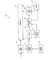
図3に示すように、CD−ROM42に記憶された医用画像表示プログラム100は、画像取得部110、注目箇所指定部120、注目箇所設定部130、計測部140、位置・角度ずれ算出部150、計測補正部160、選択部170、および画像表示部180で構成されている。
As shown in FIG. 3, the medical
CD−ROM42は、診断装置30のCD−ROMドライブ305に装填され、CD−ROM42に記憶された医用画像表示プログラム100が診断装置30にアップロードされてハードディスク装置303に記憶される。そして、この医用画像表示プログラム100が起動されて実行されることにより、診断装置30内に本発明の画像表示装置の一実施形態である医用画像表示装置200(図4参照)が構築される。
The CD-
尚、上記では、医用画像表示プログラム100を記憶する記憶媒体としてCD−ROM42が例示されているが、医用画像表示プログラム100を記憶する記憶媒体はCD−ROMに限られるものではなく、それ以外の光ディスク、MO、FD、磁気テープなどの記憶媒体であってもよい。また、医用画像表示プログラム100は、記憶媒体を介さずに、I/Oインタフェース306を介して直接に診断装置30に供給されるものであってもよい。
In the above description, the CD-
医用画像表示プログラム100の各部の詳細については、医用画像表示装置200の各部の作用と一緒に説明する。
Details of each part of the medical
図4は、医用画像表示装置200の機能ブロック図である。
FIG. 4 is a functional block diagram of the medical
医用画像表示装置200は、画像取得部210と、注目箇所指定部220と、注目箇所設定部230と、計測部240と、位置・角度ずれ算出部250と、計測補正部260と、選択部270と、画像表示部280とを有している。
The medical
医用画像表示装置200を構成する、画像取得部210と、注目箇所指定部220と、注目箇所設定部230と、計測部240と、位置・角度ずれ算出部250と、計測補正部260と、選択部270と、画像表示部280は、図3の医用画像表示プログラム100を構成する、画像取得部110、注目箇所指定部120、注目箇所設定部130、計測部140、位置・角度ずれ算出部150、計測補正部160、選択部170、および画像表示部180にそれぞれ対応する。
The
図4の各要素は、コンピュータのハードウェアとそのコンピュータで実行されるOSやアプリケーションプログラムとの組合せで構成されているのに対し、図3に示す医用画像表示プログラム100の各要素はそれらのうちのアプリケーションプログラムのみにより構成されている点が異なる。
Each element in FIG. 4 is configured by a combination of computer hardware and an OS or application program executed on the computer, whereas each element of the medical
図5は、図4に示す医用画像表示装置200において、管理サーバ20から医用画像を取得し、その取得した医用画像と医用画像上の病変領域のサイズを表示するまでの一連の処理の流れを示すフローチャート図である。
FIG. 5 shows a flow of a series of processes in the medical
以下、図5のフローチャートに従って、図4に示す医用画像表示装置200の各要素の動作について説明することによって、図3に示す医用画像表示プログラム100の各要素も併せて説明する。
Hereinafter, by describing the operation of each element of the medical
ユーザが図1に示すマウス34やキーボード33を使って、診断を行う被検体の氏名や識別番号を入力すると、その入力内容が図2のI/Oインタフェース306を介して管理サーバ20に伝えられる。管理サーバ20では、診断装置30から伝えられた氏名や識別番号と対応付けられた医用画像とカルテが診断装置30に向けて送られる。
When the user inputs the name and identification number of the subject to be diagnosed using the
管理サーバ20から送られてきた医用画像は、図4に示す画像取得部210で取得される(図5のステップS1)。
The medical image sent from the
図6は、管理サーバ20から送られてくる医用画像のイメージを示す図である。
FIG. 6 is a diagram showing an image of a medical image sent from the
図1に示すMRI装置12では、被検体Pを検査台上の所定位置に頭を合わせて寝かせた状態で、被検体Pを胸から足の付け根までが含まれる撮影範囲内で所定間隔ごとに切断したときの各断面が撮影される。撮影された複数の断面画像には、各断面画像の、撮影範囲内における切断位置の座標X0〜Xnが付加される。本実施形態では、相互に異なる時期に、MRI装置12を使って同じ被検体Pが2度撮影され、それら各撮影において、複数の断面画像で構成される断面画像群310,320が生成されて、管理サーバ20に記憶されている。画像取得部210では、これら2回分の断面画像群310,320が取得され、取得された断面画像群310,320が画像表示部280、および注目箇所設定部230に伝えられる。
In the
画像表示部280は、画像取得部210から伝えられた断面画像群310,320が含まれた断面画像表示画面410(図7参照)を図1に示す表示画面32a上に表示する。画像表示部280は、本発明にいう画像表示部の一例に相当する。
The
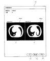
図7は、断面画像表示画面の一例を示す図である。 FIG. 7 is a diagram illustrating an example of a cross-sectional image display screen.
図7に示す断面画像表示画面410には、断面画像群310,320を構成する断面画像のうち、1つの切断位置X0における断面画像310_X0,320_X0が表示されており、それら断面画像310_X0,320_X0の切断位置や、撮影日や、被検体名なども表示されている。また、断面画像表示画面410には、断面画像310_X0,320_X0上の病変領域のサイズを計測するのにあたり、計測方向や計測位置を一方の断面画像側に合わせるための一方ボタン411、病変領域の変化量が大きい計測方向や計測位置に合わせるための変化量ボタン412、および2つの断面画像それぞれの計測方向や計測位置の中間に合わせる中間ボタン413も備えられている。
The cross-sectional
本実施形態の医用画像表示装置200では、まず、2つの断面画像310_X0,320_X0のうちの一方の断面画像上で注目箇所P1が設定される(図5のステップS2)。図7の例では、ユーザが図1に示すマウス34を使って左側の断面画像310_X0上で注目点をクリックし、さらに、一方ボタン411、変化量ボタン412、および中間ボタン413のうちのいずれかのボタンをクリックすると、図4に示す注目箇所指定部220から注目箇所設定部230に、クリックされた注目点の位置が伝えられるとともに、選択部270から計測補正部260に、選択されたボタンの情報が伝えられる。
In the medical
注目箇所設定部230は、断面画像310_X0,320_X0のうちの、注目点が指定された断面画像については、その指定された注目点を注目箇所P1と決定し、注目点が指定されなかった断面画像については、他方の断面画像に対して決定された注目箇所と同じ箇所を注目箇所P2に決定する。図7の例では、左側の断面画像310_X0上の病変箇所がクリックされることにより、その病変箇所が注目箇所P1と決定され、右側の断面画像320_X0上の、注目箇所P1に対応する箇所が注目箇所P2と決定される。決定された注目箇所P1,P2の位置と、断面画像群310,320は、計測部240に伝えられる。注目箇所指定部220と注目箇所設定部230とを合わせたものは、本発明にいう指定部の一例に相当する。
Of the cross-sectional images 310_X0 and 320_X0, the spot-of-
計測部240は、断面画像310_X0,320_X0上の注目箇所P1,P2を含む病変領域の長径および短径を計測する(図5のステップS3)。計測部240は、本発明にいう第1計測部の一例に相当する。
The
注目箇所P1,P2を含む病変領域の長径および短径を計測する方法について、簡単に説明する。 A method for measuring the major axis and minor axis of the lesion area including the attention points P1 and P2 will be briefly described.
近年、様々なシーンで撮影された複数のサンプル画像それぞれに対して、画素値の最大値、最小値、平均値、中間値などといった多数種類の画像的特徴量を算出して、各シーンとその画像的特徴との対応をコンピュータで学習させるマシンラーニングが広く利用されている。このマシンラーニングを用いると、人間では扱いきれない数の特徴量を用いることができるとともに、人間の推測力では思いもつかないような相関関係が見つかって、精度の高い判別が実現することが知られている。本実施形態の計測部240には、断面画像中の、予め腫瘍等と分かっている病変領域における標準的な画像的特徴が記憶されており、マシンラーニングを利用して病変領域の探索が行われる。
In recent years, for each of a plurality of sample images taken in various scenes, various types of image features such as maximum value, minimum value, average value, and intermediate value of pixel values are calculated, Machine learning in which correspondence with image features is learned by a computer is widely used. Using this machine learning, it is known that a number of features that cannot be handled by humans can be used, and correlations that are unthinkable by human guessing power are found, thus realizing highly accurate discrimination. ing. In the
計測部240では、まず、各断面画像310_X0,320_X0上の、注目箇所P1,P2を取り囲む注目領域R1,R2が決定される。この注目領域R1,R2の大きさは、一般的な腫瘍等が確実に含まれる経験的な値として予め用意されている。
In the
続いて、各注目領域R1,R2を構成している各画素の画像的特徴が分析され、各注目領域R1,R2を構成している画素のうち、予め保存されている病変部分の画像的特徴と合致する画素が探索される。 Subsequently, the image features of each pixel constituting each region of interest R1, R2 are analyzed, and among the pixels constituting each region of interest R1, R2, the image feature of a lesion portion stored in advance is stored. Pixels that match are searched.
さらに、病変部分の画像的特徴と合致した画素に対し、各画素が病変部分の輪郭を構成する画素であるか否かが評価され、注目領域R1,R2の中から、注目箇所P1,P2を含む病変部分であると予測される病変領域S1,S2の輪郭が抽出される。 Further, it is evaluated whether or not each pixel is a pixel constituting the contour of the lesion part for the pixel that matches the image feature of the lesion part, and the attention points P1 and P2 are selected from the attention regions R1 and R2. The contours of the lesion areas S1 and S2 that are predicted to be the included lesion parts are extracted.
病変領域S1,S2の輪郭が抽出されると、各病変領域S1,S2の長径と短径とが計測される。 When the contours of the lesion areas S1 and S2 are extracted, the major axis and minor axis of each lesion area S1 and S2 are measured.
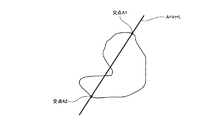
図8は、輪郭が抽出された病変領域の一例を示す図である。 FIG. 8 is a diagram illustrating an example of a lesion area from which a contour is extracted.
病変領域Sの長径および短径を表わす線分Aは、領域の重心を原点とし、線分の向きを「V」、線分の位置を「L」とすると、媒介変数tを用いて、
A=V×t+L ・・・(1)
と表わされる。また、病変領域Sの、位置L、方向Vにおける距離T(L,V)は、それら位置L,方向Vから得られる式(1)の線分Aと、病変領域Sの輪郭線との交点のうち、最も端にある2つの交点A1,A2の距離である。すなわち、線分Aと病変領域Sとの共通領域における媒介変数tの最小値を「t1」、最大値を「t2」としたときに、
A1=V×t1+L
A2=V×t2+L ・・・(2)
となり、距離T(L,V)は、
T(L,V)=|V×t1−V×t2| ・・・(3)
と表わされる。
The line segment A representing the major axis and minor axis of the lesion area S has the center of gravity of the area as the origin, the direction of the line segment is “V”, and the position of the line segment is “L”.
A = V × t + L (1)
It is expressed as Further, the distance T (L, V) in the position L and the direction V of the lesion area S is the intersection of the line segment A of the formula (1) obtained from the position L and the direction V and the contour line of the lesion area S. Is the distance between the two intersections A1 and A2 at the end. That is, when the minimum value of the parameter t in the common area of the line segment A and the lesion area S is “t1” and the maximum value is “t2”,
A1 = V × t1 + L
A2 = V × t2 + L (2)
And the distance T (L, V) is
T (L, V) = | V × t1−V × t2 | (3)
It is expressed as
各断面画像310_X0,320_X0それぞれについて、長径および短径それぞれの位置L、方向Vが算出され、式(3)で表わされる距離が長径および短径の計測値として算出される。断面画像310_X0,320_X0それぞれにおける長径および短径の位置L,方向V,線分A,および計測値は、位置・角度ずれ算出部250に伝えられる。
For each of the cross-sectional images 310_X0 and 320_X0, the position L and the direction V of the major axis and the minor axis are calculated, and the distance represented by the expression (3) is calculated as a measured value of the major axis and the minor axis. The position L, the direction V, the line segment A, and the measurement value of the major axis and the minor axis in each of the cross-sectional images 310_X0 and 320_X0 are transmitted to the position / angle
上述した、注目箇所P1,P2の指定を受けて、その注目箇所P1,P2を含む病変領域S1,S2の輪郭を抽出し、さらに病変領域S1,S2の長径および短径を計測する一連の処理は、ワンクリック計測として考案されている技術である。 A series of processes in which the contours of the lesion areas S1 and S2 including the attention areas P1 and P2 are extracted in response to the designation of the attention areas P1 and P2, and the major and minor diameters of the lesion areas S1 and S2 are measured. Is a technology devised as one-click measurement.
位置・角度ずれ算出部250では、各断面画像310_X0,320_X0それぞれの長径・短径の位置および方向のずれ量が算出される(図5のステップS4)。例えば、断面画像310_X0の長径の位置L1,方向V1とし、断面画像320_X0の長径の位置L2,方向V2とすると、長径の位置ずれ量は|L1−L2|となり、長径の方向ずれ量は|V1−V2|となる。短径についても、同様に算出される。
The position / angle
さらに、位置・角度ずれ算出部250では、算出された長径および短径の位置ずれ量と方向ずれ量が全て所定の基準レベル以下であるか否かが判定される。位置ずれ量および方向ずれ量が全て基準レベル以下である場合は(図5のステップS5:No)、位置・角度ずれ算出部250から計測補正部260に、断面画像310_X0,320_X0それぞれにおける長径および短径の位置L,方向V,線分A,および計測値が伝えられる。
Further, the position / angle
位置ずれ量および方向ずれ量のうち、基準レベルを超えるものがある場合は(図5のステップS5:Yes)、位置・角度ずれ算出部250から選択部270に、警告通知指示が伝えられる。選択部270は、画像表示部280に警告通知画面を表示する指示を伝える。位置・角度ずれ算出部250と選択部270とを合わせたものは、本発明にいう許可請求部の一例に相当する。
If any of the positional deviation amount and the direction deviation amount exceeds the reference level (step S5 in FIG. 5: Yes), a warning notification instruction is transmitted from the position / angle
画像表示部280は、選択部270から指示が伝えられると、表示画面32a上に、「病変の形状が大きく変化しています」というメッセージとともに、病変領域の計測を継続するか否かを選択するための選択画面(図示しない)を表示する(図5のステップS6)。
When the instruction is transmitted from the
ユーザが選択画面上で計測の中止を選択すると(図5のステップS6:No)、病変領域の計測が中止される。複数の断面画像間で病変領域の位置ずれや方向ずれが大きい場合、その病変の形状が大きく変化しているため、より綿密な検査が必要となる場合がある。本実施形態の医療診断システムによると、複数の断面画像間で病変領域の位置ずれや方向ずれが基準レベルを超える場合には、警告用メッセージが表示されて計測の継続/中止が選択されるため、不要な処理を省くことができるとともに、ユーザに病変の形状が大きく変化していることを知らせることができる。 When the user selects to cancel the measurement on the selection screen (step S6: No in FIG. 5), the measurement of the lesion area is stopped. If the position shift or the direction shift of the lesion area is large between a plurality of cross-sectional images, the shape of the lesion has changed greatly, and thus a closer examination may be necessary. According to the medical diagnosis system of the present embodiment, when the positional deviation or direction deviation of a lesion area between a plurality of cross-sectional images exceeds a reference level, a warning message is displayed and measurement continuation / cancellation is selected. Unnecessary processing can be omitted, and the user can be informed that the shape of the lesion has changed greatly.
また、ステップS4において位置ずれ量および方向ずれ量が全て基準レベル以下である場合や(図5のステップS5:No)、ステップS6において計測の継続が選択された場合には(図5のステップS7:Yes)、選択部270から計測補正部260に向けて計測値を補正する指示が伝えられる。
Further, when the positional deviation amount and the direction deviation amount are all below the reference level in step S4 (step S5: No in FIG. 5), or when continuation of measurement is selected in step S6 (step S7 in FIG. 5). : Yes), an instruction to correct the measurement value is transmitted from the
計測補正部260では、断面画像310_X0,320_X0それぞれに写っている病変領域のサイズを計測する共通の計測方向と計測位置とが決定され、各断面画像310_X0,320_X0上の病変領域における、共通の計測方向と計測位置のサイズが算出される(図5のステップS8)。計測補正部260は、本発明にいう最大方向判別部の一例にあたるとともに、本発明にいう第2計測部の一例に相当する。
In the
計測補正部260では、図7に示す一方ボタン411、変化量ボタン412、および中間ボタン413のうちユーザによって選択されたボタンに応じて、計測値の補正が行われる。
The
図7に示す一方ボタン411が選択されている場合、ユーザが注目店を指定した左側の断面画像310_X0で求められた計測位置L1,計測方向V1がそのまま他方の断面画像320_X0の計測に用いられて、その計測位置L1,計測方向V1でも距離T2(L1,V1)が図8および式(2)(3)で説明した計測方法で計測される。長径についての計測が終了すると、短径についても同様の処理が実行される。
When the one
また、図7に示す変化量ボタン412が選択されている場合、病変領域の形状の変化量が大きい計測位置および計測方向における計測値が算出される。例えば、断面画像310_X0上の病変領域の長径の計測位置L1,計測方向V1,そのときの長径の長さをT1(L1,V1)とし、断面画像320_X0上の病変領域の長径の計測位置L2,計測方向V2,そのときの長径の長さをT2(L2,V2)とすると、各断面画像310_X0,320_X0における計測位置と計測方向とのセット(L1,V1),(L2,V2)が両方の病変領域に用いられて、図8および式(2)(3)で説明した計測方法で距離T1(L1,V1)、T2(L1,V1)、T1(L2、V2)、T2(L2,V2)が計測される。そして、それらの距離T1(L1,V1)、T2(L1,V1)、T1(L2、V2)、T2(L2,V2)が用いられて、断面画像310_X0の計測位置L1,方向V1のときの計測値の差分S(L1,V1)が、
S(L1,V1)=|T1(L1,V1)−T2(L1,V1)| ・・・(4)
に示す式(4)によって算出され、断面画像320_X0の計測位置L2,方向V2のときの計測値の差分S(L2,V2)が、
S(L2,V2)=|T1(L2,V2)−T2(L2,V2)| ・・・(5)
に示す式(5)によって算出される。
When the
S (L1, V1) = | T1 (L1, V1) −T2 (L1, V1) | (4)
The difference S (L2, V2) between the measurement values calculated by the equation (4) shown in FIG.
S (L2, V2) = | T1 (L2, V2) −T2 (L2, V2) | (5)
It is calculated by the equation (5) shown below.
さらに、差分が最大となる計測方向の計測値が採用される。すなわち、差分S(L1,V1)>差分(L2,V2)の場合には、病変領域の計測位置と計測方向が断面画像310_X0の計測位置L1,方向V1に合わせられ、断面画像310_X上の病変領域の計測値は、計測部240で算出されたままの計測値T1(L1,V1)に決定され、断面画像320_X上の病変領域の計測値は、計測値T2(L1,V1)に決定される。また、差分S(L1,V1)≦差分(L2,V2)の場合には、病変領域の計測位置と計測方向が断面画像320_X0の計測位置L2,方向V2に合わせられ、断面画像310_X上の病変領域の計測値は、計測値T1(L2,V2)に決定され、断面画像320_X上の病変領域の計測値は、計測部240で算出されたままの計測値T2(L2,V2)に決定される。短径についても、同様に算出される。この補正方法によると、病変領域の、最も形状が変化している方向の計測値が求められるため、治療の効果や病変の変化をより正確に確認することができる。
Furthermore, the measurement value in the measurement direction that maximizes the difference is employed. That is, when difference S (L1, V1)> difference (L2, V2), the measurement position and measurement direction of the lesion area are matched with the measurement position L1 and direction V1 of the cross-sectional image 310_X0, and the lesion on the cross-sectional image 310_X. The measurement value of the area is determined as the measurement value T1 (L1, V1) as calculated by the
図7に示す中間ボタン413が選択されている場合、複数の断面画像それぞれの計測方向や計測位置の平均の位置および方向における計測値が算出される。まず、断面画像310_X0,20_X0それぞれの計測位置L1,L2の平均位置ML=(L1+L2)/2と、断面画像310_X0,20_X0それぞれの計測方向V1,V2の平均方向MV=(V1+V2)/2とが算出され、断面画像310_X0,20_X0それぞれの病変領域における、平均位置ML、および平均方向MVの計測値T1(ML,MV),T2(ML,MV)が算出される。この補正方法によると、複数の医用画像それぞれに写っている病変の、平均したサイズの変化量を確認することができる。
When the
以上のようにして算出された計測値は、計測補正部260から画像表示部280に伝えられる。画像表示部280では、図7に示す断面画像表示画面410上に、断面画像310_X0,320_X0に加えて、算出された長径および短径の計測値が表示される(図5のステップS9)。
The measurement value calculated as described above is transmitted from the
図9は、長径および短径の計測値が表示された断面画像表示画面の一例を示す図である。 FIG. 9 is a diagram illustrating an example of a cross-sectional image display screen on which measured values of the long diameter and the short diameter are displayed.
図9に示す断面画像表示画面410では、断面画像310_X0,320_X0に加えて、それら断面画像310_X0,320_X0に写っている病巣領域の長径および短径が示されている。このため、病巣領域の増減が小さい場合、断面画像310_X0,320_X0だけを見比べてもその変化がわかりにくいが、図9では、長径と短径が数字で示されているため、病状の微妙な変化も確認することができる。また、本実施形態においては、断面画像310_X0,320_X0のうちの一方の画像上で病巣箇所を指定するだけで、断面画像310_X0,320_X0それぞれに写っている病巣領域の同じ位置および方向の長径と短径が計測されるため、診断に有用な正確な情報を容易に得ることができる。
In the cross-sectional
以上で、本発明の第1実施形態の説明を終了し、本発明の第2実施形態について説明する。本発明の第2実施形態は、第1実施形態とほぼ同様の構成を有しているため、第1実施形態と同じ要素については同じ符号を付して説明を省略し、第1実施形態との相違点についてのみ説明する。 Above, description of 1st Embodiment of this invention is complete | finished and 2nd Embodiment of this invention is described. Since the second embodiment of the present invention has substantially the same configuration as that of the first embodiment, the same elements as those of the first embodiment are denoted by the same reference numerals, and the description thereof is omitted. Only the differences will be described.
図10は、本実施形態における医用画像表示プログラム100´が記憶されたCD−ROM42´を示す概念図である。
FIG. 10 is a conceptual diagram showing a CD-
図10に示すように、CD−ROM42´に記憶された医用画像表示プログラム100´は、図3に示す第1実施形態の医用画像表示プログラム100と同様の画像取得部110、注目箇所指定部120、注目箇所設定部130、計測部140、位置・角度ずれ算出部150、計測補正部160、選択部170、および画像表示部180に加えて、位置ずれ補正部190が備えられている。
As shown in FIG. 10, the medical
図3に示すCD−ROM42に替えて、図10に示すCD−ROM42´が診断装置30のCD−ROMドライブ305に装填され、CD−ROM42´に記憶された医用画像表示プログラム100´が診断装置30にアップロードされてハードディスク装置303に記憶される。そして、この医用画像表示プログラム100´が起動されて実行されることにより、診断装置30内に本発明の画像表示装置の第2実施形態である医用画像表示装置200´(図11参照)が構築される。
In place of the CD-
図11は、医用画像表示装置200´の機能ブロック図である。
FIG. 11 is a functional block diagram of the medical
医用画像表示装置200´は、図4に示す第1実施形態の医用画像表示装置200と同様の、画像取得部210と、注目箇所指定部220と、注目箇所設定部230と、計測部240と、位置・角度ずれ算出部250と、計測補正部260と、選択部270と、画像表示部280とを有しているとともに、位置ずれ補正部290が備えられている。
The medical
本実施形態の医用画像表示装置200´では、図7に示す断面画像310_X0,320_X0上で注目点が指定され、計測部240でワンクリック計測が実行されることによって、注目点を含む病変領域R1,R2の輪郭が抽出されて、長径および短径が計測されると、その抽出された病変領域R1,R2が位置ずれ補正部290に伝えられる。
In the medical
位置ずれ補正部290では、断面画像310_X0,320_X0それぞれに対して抽出された病変領域R1,R2の位置を合わせる変換行列が生成されることにより、それら病変領域R1,R2の位置ずれが検出される。
The positional
図12は、病変領域R1,R2の位置合わせ方法を示すフローチャート図である。 FIG. 12 is a flowchart showing a method for aligning lesion areas R1 and R2.
ここでは、病変領域R1,R2の重なりが最も大きくなる剛体変換(本実施形態においては、平行移動と回転との組み合わせによる線形変換)が逐次処理によって算出される。 Here, a rigid transformation (in this embodiment, a linear transformation based on a combination of translation and rotation) that maximizes the overlap between the lesion areas R1 and R2 is calculated by sequential processing.
剛体変換を実行するための剛体変換行列Mの初期行列として、病変領域R1,R2の重心を合わせる平行移動を実行するための変換行列が設定されている。 As an initial matrix of the rigid body transformation matrix M for performing the rigid body transformation, a transformation matrix for performing the parallel movement that matches the centroids of the lesion regions R1 and R2 is set.
まず、断面画像310_X0,320_X0が変換行列Mによって位置合わせされ、病変領域R1,R2の重なり度合いを評価するための一致係数が算出される(図12のステップS31)。ここでは、断面画像310_X0,320_X0中の、病変領域R1,R2が重なっている重なり部分の面積の総和が一致係数として算出される。 First, the cross-sectional images 310_X0 and 320_X0 are aligned by the transformation matrix M, and a coincidence coefficient for evaluating the overlapping degree of the lesion areas R1 and R2 is calculated (step S31 in FIG. 12). Here, the sum of the areas of the overlapping portions where the lesion regions R1 and R2 overlap in the cross-sectional images 310_X0 and 320_X0 is calculated as the coincidence coefficient.
続いて、剛体変換行列Mに基づいて、所定量の平行移動および回転を加えた新たな変換行列M´が生成される(図12のステップS32)。 Subsequently, a new transformation matrix M ′ to which a predetermined amount of translation and rotation has been added is generated based on the rigid transformation matrix M (step S32 in FIG. 12).
変換行列M´が生成されると、断面画像310_X0,320_X0が変換行列M´によって位置合わせされ、ステップS31と同様にして、一致係数が算出される。一致係数が増加した場合(図12のステップS33:Yes)、病変領域R1,R2の重なり面積が増加したことを表わし、新たに生成された変換行列M´が剛体変換行列Mに設定される(図12のステップS34)。 When the transformation matrix M ′ is generated, the cross-sectional images 310_X0 and 320_X0 are aligned by the transformation matrix M ′, and the coincidence coefficient is calculated in the same manner as in step S31. When the coincidence coefficient increases (step S33 in FIG. 12: Yes), it indicates that the overlapping area of the lesion regions R1 and R2 has increased, and the newly generated transformation matrix M ′ is set as the rigid transformation matrix M ( Step S34 in FIG.
さらに、新たな剛体変換行列Mに基づいて、所定量の平行移動および回転を加えた変換行列M´が生成され、断面画像310_X0,320_X0が生成された変換行列M´によって位置合わせされた後で一致係数が算出される。ステップS32からステップS34の処理は、一致係数が増加しなくなるまで繰り返し実行される。 Furthermore, after a transformation matrix M ′ to which a predetermined amount of translation and rotation has been added is generated based on the new rigid transformation matrix M, and the cross-sectional images 310_X0 and 320_X0 are aligned by the generated transformation matrix M ′. A coincidence coefficient is calculated. The processing from step S32 to step S34 is repeatedly executed until the coincidence coefficient does not increase.
一致係数が増加しない場合(図12のステップS34:No)、剛体変換行列Mの変更が行われず、今度は新たな基準の一致係数が算出される(図15のステップS35)。ここでは、断面画像310_X0,320_X0において、各病変領域R1,R2が重なっている重なり部分の面積S、重なり部分の濃度値の相関係数Nを使って、
一致係数=aS×bN ・・・(6)
で算出される。式(6)中の係数a,bは、病変部の種類などに応じて設定される。
When the coincidence coefficient does not increase (step S34 in FIG. 12: No), the rigid transformation matrix M is not changed, and a new reference coincidence coefficient is calculated (step S35 in FIG. 15). Here, in the cross-sectional images 310_X0 and 320_X0, by using the area S of the overlapping portion where the lesion areas R1 and R2 overlap each other and the correlation coefficient N of the density value of the overlapping portion,
Coincidence factor = aS × bN (6)
Is calculated by Coefficients a and b in equation (6) are set according to the type of lesion.
続いて、剛体変換行列Mに基づいて、所定量の平行移動および回転に加えて、濃度値を補正を加えた新たな変換行列M´´が生成される(図12のステップS36)。 Subsequently, on the basis of the rigid body transformation matrix M, a new transformation matrix M ″ in which density values are corrected in addition to a predetermined amount of translation and rotation is generated (step S36 in FIG. 12).
変換行列M´´が生成されると、断面画像310_X0,320_X0が変換行列M´´によって位置合わせされ、ステップS35と同様に一致係数が算出される。一致係数が増加した場合(図12のステップS37:Yes)、新たに生成された変換行列M´´が剛体変換行列Mに設定される(図12のステップS38)。 When the transformation matrix M ″ is generated, the cross-sectional images 310_X0 and 320_X0 are aligned by the transformation matrix M ″, and the coincidence coefficient is calculated as in step S35. When the coincidence coefficient increases (step S37 in FIG. 12: Yes), the newly generated transformation matrix M ″ is set as the rigid transformation matrix M (step S38 in FIG. 12).
ステップS36からステップS38までの処理が、一致係数が増加しなくなるまで繰り返し実行される。 The processing from step S36 to step S38 is repeatedly executed until the coincidence coefficient does not increase.
以上のようにに剛体変換行列Mが算出されることによって、断面画像320_X0上の病変領域の位置および角度を、断面画像310_X0上の病変領域の位置および角度に合わせるための移動距離および回転角度といった位置合わせ情報が得られる。本実施形態においては、この時点では実際に位置合わせは行われず、剛体変換行列Mと位置合わせ情報の取得のみが行われる。 By calculating the rigid transformation matrix M as described above, the moving distance and the rotation angle for adjusting the position and angle of the lesion area on the cross-sectional image 320_X0 to the position and angle of the lesion area on the cross-sectional image 310_X0, etc. Registration information is obtained. In the present embodiment, the alignment is not actually performed at this time, and only the rigid transformation matrix M and the alignment information are acquired.
算出された剛体変換行列Mと、位置合わせ情報は、位置・角度ずれ算出部250に伝えられる。
The calculated rigid body transformation matrix M and alignment information are transmitted to the position / angle
位置・角度ずれ算出部250では、位置合わせが行われた断面画像310_X0,320_X0それぞれの長径・短径の位置および方向のずれ量が推測される。
The position / angle
図13は、長径・短径の位置および方向のずれ量の推測方法の概念図である。 FIG. 13 is a conceptual diagram of a method for estimating the amount of deviation in the position and direction of the major axis and minor axis.
位置・角度ずれ算出部250では、位置ずれ補正部290から伝えられた位置合わせ情報に基づいて、断面画像320_X0上の病変領域(図13の抽出輪郭1)を、断面画像310_X0上の病変領域(抽出輪郭2)の位置および角度に合わせたときの、補正後の断面画像320_X0上の病変領域(変更後の抽出輪郭1)が推測される。この推測された病変領域(変更後の抽出輪郭1)が断面画像310_X0上の病変領域(抽出輪郭1)と一致する場合、病変の大きさは変化していないと考えられる。
In the position / angle
長径および短径の位置ずれ量と方向ずれ量のうち、基準値よりも大きいものがある場合は、第1実施形態と同様に、位置・角度ずれ算出部250から選択部270に警告通知指示が伝えられ、表示画面32a上に、「病変の形状が大きく変化しています」というメッセージと、病変領域の計測を継続するか否かを選択するための選択画面とが表示される。
If there is an amount of positional deviation and direction deviation of the major axis and minor axis that is larger than the reference value, a warning notification instruction is issued from the position / angle
また、長径および短径の位置ずれ量と方向ずれ量が全て基準値以下である場合や、選択画面を使って計測の継続が選択された場合、計測補正部260では、図7に示す一方ボタン411、変化量ボタン412、および中間ボタン413のうちユーザによって選択されたボタンに応じて、計測値の補正が行われる。尚、本実施形態においては、計測補正部260において、位置ずれ補正部290で算出された剛体変換行列Mを用いて、位置ずれが考慮された計測値の算出が実行される。
When the major axis and minor axis positional deviation amount and the direction deviation amount are all equal to or less than the reference value, or when continuation of measurement is selected using the selection screen, the
以下では、断面画像310_X0上の病変領域の長径の位置L1,方向V1,そのときの長径の長さをT1(L1,V1)とし、断面画像320_X0上の病変領域の長径の位置L2,方向V2,そのときの長径の長さをT2(L2,V2)とし、さらに、位置ずれ補正部290で算出された剛体変換行列Mを使った変換式をFfとし、その変換式の逆変換式をFbとして説明する。
Hereinafter, the position L1 of the major axis of the lesion area on the cross-sectional image 310_X0, the direction V1, the length of the major axis at that time is T1 (L1, V1), the position L2 of the major axis of the lesion area on the cross-sectional image 320_X0, and the direction V2 , The length of the major axis at that time is T2 (L2, V2), the conversion equation using the rigid body transformation matrix M calculated by the
図7に示す一方ボタン411が選択されている場合、断面画像310_X0上で注目点が指定された場合には、断面画像320_Xの長径の計測値がT2(Ff(L1),Ff(V1))に補正される。逆に、断面画像320_X0上で注目点が指定された場合には、断面画像310_Xの長径の計測値がT1(Fb(L2),Fb(V2))に補正される。
When the one
また、図7に示す変化量ボタン412が選択されている場合、上述した式(4)が、
S(L1,V1)=|T1(L1,V1)−T2(Ff(L1),Ff(V1))|
・・・(4)´
と変更され、上述した式(5)が、
S(L2,V2)=|T1(Fb(L2),Fb(V2))−T2(L2,V2)|
・・・(5)´
と変更される。さらに、式(4)´および式(5)´に示す差分S(L1,V1)>差分(L2,V2)の場合には、病変領域の計測位置と計測方向が断面画像310_X0の計測位置L1,方向V1に合わせられ、断面画像310_X上の病変領域の計測値は、計測部240で算出されたままの計測値T1(L1,V1)に決定され、断面画像320_X上の病変領域の計測値は、計測値T2(Ff(L1),Ff(V1))に決定される。また、差分S(L1,V1)≦差分(L2,V2)の場合には、病変領域の計測位置と計測方向が断面画像320_X0の計測位置L2,方向V2に合わせられ、断面画像310_X上の病変領域の計測値は、計測値T1(Fb(L2),Fb(V2))に決定され、断面画像320_X上の病変領域の計測値は、計測部240で算出されたままの計測値T2(L2,V2)に決定される。
When the
S (L1, V1) = | T1 (L1, V1) −T2 (Ff (L1), Ff (V1)) |
... (4) '
And the above-described equation (5) becomes
S (L2, V2) = | T1 (Fb (L2), Fb (V2)) − T2 (L2, V2) |
... (5) '
And changed. Further, in the case of the difference S (L1, V1)> difference (L2, V2) shown in Expression (4) ′ and Expression (5) ′, the measurement position and measurement direction of the lesion area are the measurement position L1 of the cross-sectional image 310_X0. , The measurement value of the lesion area on the cross-sectional image 310_X is determined to be the measurement value T1 (L1, V1) as calculated by the
図7に示す中間ボタン413が選択されている場合、断面画像310_X上の病変領域の長径の位置Lg1と、長径の方向Vg1は、
Lg1=(L1+Fb(L2))/2
Vg1=(V1+Fb(V2))/2 ・・・(7)
に補正され、長径の計測値は、T1(Lg1,Vg1)に決定される。
When the
Lg1 = (L1 + Fb (L2)) / 2
Vg1 = (V1 + Fb (V2)) / 2 (7)
The major axis measurement value is determined as T1 (Lg1, Vg1).
また、断面画像320_X上の病変領域の長径の位置Lg2と、長径の方向Vg2は、
Lg2=(Ff(L1)+L2)/2
Vg2=(Ff(V1)+V2)/2 ・・・(8)
に補正され、長径の計測値は、T2(Lg2,Vg2)に決定される。
The major axis position Lg2 of the lesion area on the cross-sectional image 320_X and the major axis direction Vg2 are:
Lg2 = (Ff (L1) + L2) / 2
Vg2 = (Ff (V1) + V2) / 2 (8)
The major axis measurement value is determined as T2 (Lg2, Vg2).
算出された計測値は、計測補正部260から画像表示部280に伝えられ、図7に示す断面画像表示画面410上に、断面画像310_X0,320_X0に並べて、長径および短径の計測値が表示される。
The calculated measurement values are transmitted from the
以上のように、複数の医用画像それぞれに写っている病変領域間の位置ずれが考慮されることによって、それらの病変領域のサイズを精度良く算出することができる。 As described above, by taking into account the positional deviation between the lesion areas shown in each of the plurality of medical images, the sizes of those lesion areas can be calculated with high accuracy.
ここで、上記では、2つの医用画像を並べて表示する例について説明したが,本発明にいう画像表示部は、3つ以上の医用画像を表示するものであってもよい。3つ以上の医用画像を表示して、それらの医用画像上の病変領域の長径・短径を計測するのにあたり、以下のようにして長径・短径の位置や向きのずれが大きい医用画像を検索し、検索された医用画像については、長径・短径の位置合わせを行わずにワンクリック計測で求められた計測値をそのまま表示してもよい。まず、複数の医用画像それぞれについて、病変領域の長径をワンクリック計測によって計測する。続いて、計測された長径の位置および方向それぞれに対して平均と分散を求め、計測値と平均値との差の二乗が分散のK倍以上となる画像をずれが大きい医用画像と判定する。尚、Kの値は、病変の種類などに応じて変更することが好ましい。 Here, an example in which two medical images are displayed side by side has been described above, but the image display unit according to the present invention may display three or more medical images. In displaying three or more medical images and measuring the major axis and minor axis of the lesion area on those medical images, medical images with large deviations in the position and orientation of the major axis and minor axis are as follows. For the medical image searched and searched, the measurement value obtained by the one-click measurement may be displayed as it is without aligning the major axis and the minor axis. First, for each of the plurality of medical images, the major axis of the lesion area is measured by one-click measurement. Subsequently, an average and a variance are obtained for each position and direction of the measured major axis, and an image in which the square of the difference between the measured value and the average value is K times or more of the variance is determined as a medical image with a large deviation. Note that the value of K is preferably changed according to the type of lesion.
また、上記では、病変領域の長径と短径とを算出する例について説明したが、本発明にいう第1計測部および第2計測部は、短径および長径以外の所定方向の長さなどであってもよい。 Moreover, although the example which calculates the major axis and minor axis of a lesion area was demonstrated above, the 1st measurement part and 2nd measurement part said to this invention are the lengths of predetermined directions other than a minor axis and a major axis, etc. There may be.
また、上記では、断面画像上で注目点を指定する例について説明したが、本発明のサイズ計測装置および画像表示装置は、例えば、断面画像中の注目領域を指定するものであってもよい。 In the above description, an example in which a point of interest is specified on a cross-sectional image has been described. However, the size measurement device and the image display device of the present invention may specify a region of interest in a cross-sectional image, for example.
また、上記では、断面画像上でユーザが病巣と推測される注目箇所を手動で指定する例について説明したが、本発明のサイズ計測装置および画像表示装置は、例えば、断面画像中の、サンプル画像と似ている画像パターンを有する画像部分を画像処理によって検索し、その検索された画像部分を注目箇所として設定するものであってもよい。 In the above description, an example in which a user manually designates a spot of interest that is assumed to be a lesion on a cross-sectional image has been described. However, the size measurement device and the image display device of the present invention are, for example, a sample image in a cross-sectional image. An image portion having an image pattern similar to the above may be searched by image processing, and the searched image portion may be set as a point of interest.
また、本発明のサイズ計測装置および画像表示装置は、過去に撮影された断面画像上で病変部分の位置を保存しておき、新たな断面画像のセットが得られた場合に、過去の病変部分のリストを表示して、ユーザによって選択された病変部分の位置を取得して今回の注目箇所として設定するものであってもよい。 In addition, the size measurement device and the image display device of the present invention store the position of a lesion part on a cross-sectional image taken in the past, and when a new set of cross-sectional images is obtained, the past lesion part The position of the lesion part selected by the user may be acquired and set as the current point of interest.
また、本発明のサイズ計測装置および画像表示装置は、例えば、右肺野や左肺野上の注目箇所が指定された場合、それら右肺野および左肺野の中心点を注目箇所として設定してもよい。 In addition, the size measurement device and the image display device of the present invention, for example, when a point of interest on the right lung field or the left lung field is designated, sets the center point of the right lung field and the left lung field as the point of interest. Also good.
また、上記では、本発明の画像表示装置を診断装置に適用する例について説明したが、本発明の画像表示装置は、管理サーバなどに適用してもよい。 Moreover, although the example which applies the image display apparatus of this invention to a diagnostic apparatus was demonstrated above, you may apply the image display apparatus of this invention to a management server etc.
10 画像生成装置
11 CR装置
12 MRI装置
20 管理サーバ
30 診断装置
31 本体装置
32 画像表示装置
33 キーボード
34 マウス
301 CPU
302 主メモリ
303 ハードディスク装置
304 FDドライブ
305 CD−ROMドライブ
306 I/Oインタフェース
100 医用画像表示プログラム
110 画像取得部
120 注目箇所指定部
130 注目箇所設定部
140 計測部
150 位置・角度ずれ算出部
160 計測補正部
170 選択部
180 画像表示部
190 位置ずれ補正部
200 医用画像表示装置
210 画像取得部
220 注目箇所指定部
230 注目箇所設定部
240 計測部
250 位置・角度ずれ算出部
260 計測補正部
270 選択部
280 画像表示部
290 位置ずれ補正部
DESCRIPTION OF
DESCRIPTION OF
Claims (11)
前記医用画像の前記指定部で指定された箇所に写っている像のサイズを、該像の形状に応じた計測方向について計測する第1計測部と、
前記医用画像の前記指定部で指定された箇所に写っている像について、前記第1計測部における計測方向に基づいて決まる、前記複数の医用画像それぞれに共通の共通計測方向のサイズを計測する第2計測部とを備えたことを特徴とするサイズ計測装置。 A designation unit for designating a location on an image for each of a plurality of medical images obtained by imaging a subject;
A first measurement unit that measures the size of an image shown in the location designated by the designation unit of the medical image in a measurement direction according to the shape of the image;
A first measuring unit configured to measure a size in a common measurement direction common to each of the plurality of medical images, which is determined based on a measurement direction in the first measurement unit, with respect to an image of the medical image shown in the location designated by the designation unit; A size measuring device comprising two measuring units.
前記第2計測部は、前記複数の医用画像のうち、前記第1計測部で前記サイズを計測された医用画像とは別の医用画像について、前記指定部で指定された箇所に写っている像のサイズを、前記第1計測部における計測方向と同じ計測方向で計測するものであることを特徴とする請求項1から3のうちいずれか1項記載のサイズ計測装置。 The first measurement unit measures the size of the image for one medical image of the plurality of medical images,
The second measurement unit is an image of a medical image different from the medical image whose size is measured by the first measurement unit among the plurality of medical images, which is reflected in a location specified by the specification unit. The size measuring apparatus according to claim 1, wherein the size is measured in the same measurement direction as the measurement direction in the first measurement unit.
前記第2計測部は、前記複数の医用画像それぞれに写った各像のサイズを、他の像について前記第1計測部で用いられた計測方向と同じ計測方向について計測するものであり、
前記第1計測部および前記第2計測部で用いられた各計測方向のうち、像の相互間でのサイズ差が最も大きい計測方向を求める最大差方向判別部を備えたことを特徴とする請求項1から3のうちいずれか1項記載のサイズ計測装置。 The first measurement unit measures the size of each image shown in each of the plurality of medical images in each measurement direction according to the shape of each image,
The second measurement unit measures the size of each image captured in each of the plurality of medical images in the same measurement direction as the measurement direction used in the first measurement unit for other images,
A maximum difference direction discriminating unit for obtaining a measurement direction having the largest size difference between images among the measurement directions used in the first measurement unit and the second measurement unit is provided. Item 4. The size measuring device according to any one of Items 1 to 3.
前記第2計測部は、前記医用画像について前記像のサイズを、前記第1計測部における前記複数の医用画像それぞれの計測方向の平均の方向について計測するものであることを特徴とする請求項1から3のうちいずれか1項記載のサイズ計測装置。 The first measurement unit measures the size of the image for each of the plurality of medical images.
The said 2nd measurement part measures the size of the said image about the said medical image about the average direction of each measurement direction of these several medical images in the said 1st measurement part, It is characterized by the above-mentioned. 4. The size measuring device according to any one of items 3 to 3.
前記第2計測部は、前記位置ずれ補正部において検出された位置ずれを考慮して前記像のサイズを計測するものであることを特徴とする請求項1から6のうちいずれか1項記載のサイズ計測装置。 A misalignment correction unit that detects misalignment of the image between the plurality of medical images;
The said 2nd measurement part measures the size of the said image in consideration of the position shift detected in the said position shift correction | amendment part, The any one of Claim 1 to 6 characterized by the above-mentioned. Size measuring device.
前記第1計測部における前記複数の医用画像それぞれの計測方向が所定レベル以上に離れている場合に、前記第2計測部によるサイズ計測の許可を求める許可請求部を備え、
前記第2計測部は、前記許可請求部による求めに対してサイズ計測が許可された場合に、前記像のサイズを計測するものであることを特徴とする請求項1から7のうちいずれか1項記載のサイズ計測装置。 The first measurement unit measures the size of the image for each of the plurality of medical images.
A permission request unit for requesting permission for size measurement by the second measurement unit when the measurement direction of each of the plurality of medical images in the first measurement unit is more than a predetermined level;
The said 2nd measurement part measures the size of the said image, when size measurement is permitted with respect to the request | requirement by the said permission claim part, The any one of Claim 1 to 7 characterized by the above-mentioned. The size measuring device according to item.
前記医用画像の前記指定部で指定された箇所に写っている像のサイズを、該像の形状に応じた計測方向について計測する第1計測部と、
前記医用画像の前記指定部で指定された箇所に写っている像について、前記第1計測部における計測方向に基づいて決まる、前記複数の医用画像それぞれに共通の共通計測方向のサイズを計測する第2計測部と、
前記複数の医用画像を表示するとともに、前記第2計測部で計測された像のサイズを表示する表示部を備えたことを特徴とする画像表示装置。 A designation unit for designating a location on an image for each of a plurality of medical images obtained by imaging a subject;
A first measurement unit that measures the size of an image shown in the location designated by the designation unit of the medical image in a measurement direction according to the shape of the image;
A first measuring unit configured to measure a size in a common measurement direction common to each of the plurality of medical images, which is determined based on a measurement direction in the first measurement unit, with respect to an image of the medical image shown in the location designated by the designation unit; Two measuring units;
An image display device comprising: a display unit that displays the plurality of medical images and displays a size of an image measured by the second measurement unit.
被写体を撮影した複数の医用画像それぞれについて画像上の箇所を指定する指定部と、
前記医用画像の前記指定部で指定された箇所に写っている像のサイズを、該像の形状に応じた計測方向について計測する第1計測部と、
前記医用画像の前記指定部で指定された箇所に写っている像について、前記第1計測部における計測方向に基づいて決まる、前記複数の医用画像それぞれに共通の共通計測方向のサイズを計測する第2計測部とを構築することを特徴とするサイズ計測プログラム。 Executed in a computer, on the computer,
A designation unit for designating a location on an image for each of a plurality of medical images obtained by imaging a subject;
A first measurement unit that measures the size of an image shown in the location designated by the designation unit of the medical image in a measurement direction according to the shape of the image;
A first measuring unit configured to measure a size in a common measurement direction common to each of the plurality of medical images, which is determined based on a measurement direction in the first measurement unit, with respect to an image of the medical image shown in the location designated by the designation unit; A size measuring program characterized by constructing two measuring units.
被写体を撮影した複数の医用画像それぞれについて画像上の箇所を指定する指定部と、
前記医用画像の前記指定部で指定された箇所に写っている像のサイズを、該像の形状に応じた計測方向について計測する第1計測部と、
前記医用画像の前記指定部で指定された箇所に写っている像について、前記第1計測部における計測方向に基づいて決まる、前記複数の医用画像それぞれに共通の共通計測方向のサイズを計測する第2計測部と、
前記複数の医用画像を表示するとともに、前記第2計測部で計測された像のサイズを表示する表示部とを構築することを特徴とする画像表示プログラム。 Executed in a computer, on the computer,
A designation unit for designating a location on an image for each of a plurality of medical images obtained by imaging a subject;
A first measurement unit that measures the size of an image shown in the location designated by the designation unit of the medical image in a measurement direction according to the shape of the image;
A first measuring unit configured to measure a size in a common measurement direction common to each of the plurality of medical images, which is determined based on a measurement direction in the first measurement unit, with respect to an image of the medical image shown in the location designated by the designation unit; Two measuring units;
An image display program for displaying the plurality of medical images and constructing a display unit for displaying the size of the image measured by the second measurement unit.
Priority Applications (2)
| Application Number | Priority Date | Filing Date | Title |
|---|---|---|---|
| JP2007245536A JP4559460B2 (en) | 2007-09-21 | 2007-09-21 | Size measuring device, image display device, size measuring program, and image display program |
| US12/212,934 US8036439B2 (en) | 2007-09-21 | 2008-09-18 | Size measurement apparatus, image display unit, computer-readable size measurement program storage medium, and computer-readable image display program storage medium |
Applications Claiming Priority (1)
| Application Number | Priority Date | Filing Date | Title |
|---|---|---|---|
| JP2007245536A JP4559460B2 (en) | 2007-09-21 | 2007-09-21 | Size measuring device, image display device, size measuring program, and image display program |
Publications (2)
| Publication Number | Publication Date |
|---|---|
| JP2009072433A true JP2009072433A (en) | 2009-04-09 |
| JP4559460B2 JP4559460B2 (en) | 2010-10-06 |
Family
ID=40471644
Family Applications (1)
| Application Number | Title | Priority Date | Filing Date |
|---|---|---|---|
| JP2007245536A Expired - Fee Related JP4559460B2 (en) | 2007-09-21 | 2007-09-21 | Size measuring device, image display device, size measuring program, and image display program |
Country Status (2)
| Country | Link |
|---|---|
| US (1) | US8036439B2 (en) |
| JP (1) | JP4559460B2 (en) |
Cited By (5)
| Publication number | Priority date | Publication date | Assignee | Title |
|---|---|---|---|---|
| JP2015522871A (en) * | 2012-05-21 | 2015-08-06 | テラリコン インコーポレイテッド | Integration of medical recording software and advanced image processing |
| JP2016016205A (en) * | 2014-07-10 | 2016-02-01 | 富士フイルム株式会社 | Medical image measurement apparatus, method, and program |
| JP2016047235A (en) * | 2014-08-27 | 2016-04-07 | 株式会社東芝 | Medical image processor and medical image processing method |
| JP2020010805A (en) * | 2018-07-17 | 2020-01-23 | 大日本印刷株式会社 | Specification device, program, specification method, information processing device, and specifier |
| WO2022176873A1 (en) | 2021-02-22 | 2022-08-25 | 富士フイルム株式会社 | Medical image processing device, medical image processing method, and program |
Families Citing this family (3)
| Publication number | Priority date | Publication date | Assignee | Title |
|---|---|---|---|---|
| JP5364290B2 (en) * | 2008-04-17 | 2013-12-11 | 富士フイルム株式会社 | Image display apparatus, image display control method, and program |
| JP5546230B2 (en) * | 2009-12-10 | 2014-07-09 | キヤノン株式会社 | Information processing apparatus, information processing method, and program |
| JP6769173B2 (en) * | 2015-12-15 | 2020-10-14 | コニカミノルタ株式会社 | Ultrasound diagnostic imaging equipment, ultrasonic image measurement methods and programs |
Citations (3)
| Publication number | Priority date | Publication date | Assignee | Title |
|---|---|---|---|---|
| JPH11342132A (en) * | 1998-06-03 | 1999-12-14 | Ge Yokogawa Medical Systems Ltd | Angiometry and device, and imaging device for medical use |
| JP2003099021A (en) * | 2001-09-21 | 2003-04-04 | Canon Inc | Device, method, program, and storage medium for displaying picture |
| WO2005117712A1 (en) * | 2004-06-03 | 2005-12-15 | Hitachi Medical Corporation | Image diagnosis assisting method and image diagnosis assisting apparatus |
Family Cites Families (8)
| Publication number | Priority date | Publication date | Assignee | Title |
|---|---|---|---|---|
| JP2004096417A (en) | 2002-08-30 | 2004-03-25 | Mitsubishi Space Software Kk | Medical image processing device |
| TWI274843B (en) * | 2002-12-25 | 2007-03-01 | Hon Hai Prec Ind Co Ltd | System and method for obtaining measurement data on objects via processing images thereof |
| US7499579B2 (en) * | 2004-05-03 | 2009-03-03 | Carestream Health, Inc. | Method and program for comparing the size of a feature in sequential x-ray images |
| JP4820680B2 (en) * | 2006-04-12 | 2011-11-24 | 株式会社東芝 | Medical image display device |
| JP2008000536A (en) * | 2006-06-26 | 2008-01-10 | Fujifilm Corp | Image display device |
| JP4528322B2 (en) * | 2007-09-28 | 2010-08-18 | 富士フイルム株式会社 | Image display device, image display method, and image display program |
| JP4616874B2 (en) * | 2007-09-28 | 2011-01-19 | 富士フイルム株式会社 | Image display device, image display method, and image display program |
| JP2010131257A (en) * | 2008-12-05 | 2010-06-17 | Ziosoft Inc | Medical image processor and medical image processing program |
-
2007
- 2007-09-21 JP JP2007245536A patent/JP4559460B2/en not_active Expired - Fee Related
-
2008
- 2008-09-18 US US12/212,934 patent/US8036439B2/en not_active Expired - Fee Related
Patent Citations (3)
| Publication number | Priority date | Publication date | Assignee | Title |
|---|---|---|---|---|
| JPH11342132A (en) * | 1998-06-03 | 1999-12-14 | Ge Yokogawa Medical Systems Ltd | Angiometry and device, and imaging device for medical use |
| JP2003099021A (en) * | 2001-09-21 | 2003-04-04 | Canon Inc | Device, method, program, and storage medium for displaying picture |
| WO2005117712A1 (en) * | 2004-06-03 | 2005-12-15 | Hitachi Medical Corporation | Image diagnosis assisting method and image diagnosis assisting apparatus |
Cited By (6)
| Publication number | Priority date | Publication date | Assignee | Title |
|---|---|---|---|---|
| JP2015522871A (en) * | 2012-05-21 | 2015-08-06 | テラリコン インコーポレイテッド | Integration of medical recording software and advanced image processing |
| JP2016016205A (en) * | 2014-07-10 | 2016-02-01 | 富士フイルム株式会社 | Medical image measurement apparatus, method, and program |
| JP2016047235A (en) * | 2014-08-27 | 2016-04-07 | 株式会社東芝 | Medical image processor and medical image processing method |
| JP2020010805A (en) * | 2018-07-17 | 2020-01-23 | 大日本印刷株式会社 | Specification device, program, specification method, information processing device, and specifier |
| JP7167515B2 (en) | 2018-07-17 | 2022-11-09 | 大日本印刷株式会社 | Identification device, program, identification method, information processing device and identification device |
| WO2022176873A1 (en) | 2021-02-22 | 2022-08-25 | 富士フイルム株式会社 | Medical image processing device, medical image processing method, and program |
Also Published As
| Publication number | Publication date |
|---|---|
| JP4559460B2 (en) | 2010-10-06 |
| US8036439B2 (en) | 2011-10-11 |
| US20090080692A1 (en) | 2009-03-26 |
Similar Documents
| Publication | Publication Date | Title |
|---|---|---|
| JP4559460B2 (en) | Size measuring device, image display device, size measuring program, and image display program | |
| JP4528322B2 (en) | Image display device, image display method, and image display program | |
| JP5543444B2 (en) | Method and system for performing a biopsy | |
| US7855723B2 (en) | Image registration using locally-weighted fitting | |
| JP2009072432A (en) | Image display device and image display program | |
| JP5188693B2 (en) | Image processing device | |
| JP2008000536A (en) | Image display device | |
| JP5580030B2 (en) | Image processing apparatus and image alignment method | |
| JP2006512960A (en) | Image alignment method and medical image data processing apparatus | |
| JP6131161B2 (en) | Image registration apparatus, method, program, and three-dimensional deformation model generation method | |
| JP2007252904A (en) | Imaginary tomographic position setting method in 3d volume data set and medical imaging system | |
| JP2013153883A (en) | Image processing apparatus, imaging system, and image processing method | |
| US11847730B2 (en) | Orientation detection in fluoroscopic images | |
| JP4616874B2 (en) | Image display device, image display method, and image display program | |
| US10078906B2 (en) | Device and method for image registration, and non-transitory recording medium | |
| US20080292048A1 (en) | Method, tomography system and image processing system for displaying tomographic records of a patient | |
| US9020215B2 (en) | Systems and methods for detecting and visualizing correspondence corridors on two-dimensional and volumetric medical images | |
| JP6487999B2 (en) | Information processing apparatus, information processing method, and program | |
| CN116583223A (en) | Guided acquisition of 3D representations of anatomical structures | |
| EP4062838A1 (en) | Method for use in ultrasound imaging | |
| JP6925847B2 (en) | Exposure dose calculation device and exposure dose management system, their control methods and their programs | |
| JP6925846B2 (en) | Exposure dose calculation device and exposure dose management system, their control methods and their programs | |
| WO2020148407A1 (en) | System for determining a tissue-specific property |
Legal Events
| Date | Code | Title | Description |
|---|---|---|---|
| A621 | Written request for application examination |
Free format text: JAPANESE INTERMEDIATE CODE: A621 Effective date: 20100203 |
|
| A871 | Explanation of circumstances concerning accelerated examination |
Free format text: JAPANESE INTERMEDIATE CODE: A871 Effective date: 20100203 |
|
| A975 | Report on accelerated examination |
Free format text: JAPANESE INTERMEDIATE CODE: A971005 Effective date: 20100311 |
|
| A131 | Notification of reasons for refusal |
Free format text: JAPANESE INTERMEDIATE CODE: A131 Effective date: 20100316 |
|
| A521 | Request for written amendment filed |
Free format text: JAPANESE INTERMEDIATE CODE: A523 Effective date: 20100406 |
|
| A131 | Notification of reasons for refusal |
Free format text: JAPANESE INTERMEDIATE CODE: A131 Effective date: 20100511 |
|
| TRDD | Decision of grant or rejection written | ||
| A01 | Written decision to grant a patent or to grant a registration (utility model) |
Free format text: JAPANESE INTERMEDIATE CODE: A01 Effective date: 20100720 |
|
| A01 | Written decision to grant a patent or to grant a registration (utility model) |
Free format text: JAPANESE INTERMEDIATE CODE: A01 |
|
| A61 | First payment of annual fees (during grant procedure) |
Free format text: JAPANESE INTERMEDIATE CODE: A61 Effective date: 20100722 |
|
| R150 | Certificate of patent or registration of utility model |
Ref document number: 4559460 Country of ref document: JP Free format text: JAPANESE INTERMEDIATE CODE: R150 Free format text: JAPANESE INTERMEDIATE CODE: R150 |
|
| FPAY | Renewal fee payment (event date is renewal date of database) |
Free format text: PAYMENT UNTIL: 20130730 Year of fee payment: 3 |
|
| R250 | Receipt of annual fees |
Free format text: JAPANESE INTERMEDIATE CODE: R250 |
|
| R250 | Receipt of annual fees |
Free format text: JAPANESE INTERMEDIATE CODE: R250 |
|
| R250 | Receipt of annual fees |
Free format text: JAPANESE INTERMEDIATE CODE: R250 |
|
| R250 | Receipt of annual fees |
Free format text: JAPANESE INTERMEDIATE CODE: R250 |
|
| R250 | Receipt of annual fees |
Free format text: JAPANESE INTERMEDIATE CODE: R250 |
|
| R250 | Receipt of annual fees |
Free format text: JAPANESE INTERMEDIATE CODE: R250 |
|
| LAPS | Cancellation because of no payment of annual fees |