JP4297658B2 - Wheel bearing device - Google Patents
Wheel bearing device Download PDFInfo
- Publication number
- JP4297658B2 JP4297658B2 JP2002219426A JP2002219426A JP4297658B2 JP 4297658 B2 JP4297658 B2 JP 4297658B2 JP 2002219426 A JP2002219426 A JP 2002219426A JP 2002219426 A JP2002219426 A JP 2002219426A JP 4297658 B2 JP4297658 B2 JP 4297658B2
- Authority
- JP
- Japan
- Prior art keywords
- seal
- contact
- tip
- lip
- bearing
- Prior art date
- Legal status (The legal status is an assumption and is not a legal conclusion. Google has not performed a legal analysis and makes no representation as to the accuracy of the status listed.)
- Expired - Lifetime
Links
- 238000007789 sealing Methods 0.000 claims description 83
- 239000004519 grease Substances 0.000 claims description 23
- 230000000694 effects Effects 0.000 claims description 18
- 238000005096 rolling process Methods 0.000 claims description 15
- 230000003405 preventing effect Effects 0.000 claims description 13
- 230000002093 peripheral effect Effects 0.000 claims description 11
- 238000010438 heat treatment Methods 0.000 claims 3
- 230000020169 heat generation Effects 0.000 claims 2
- 239000000428 dust Substances 0.000 description 11
- XLYOFNOQVPJJNP-UHFFFAOYSA-N water Substances O XLYOFNOQVPJJNP-UHFFFAOYSA-N 0.000 description 11
- 239000000314 lubricant Substances 0.000 description 10
- 239000000470 constituent Substances 0.000 description 5
- 239000002184 metal Substances 0.000 description 5
- 229910052751 metal Inorganic materials 0.000 description 5
- 230000004048 modification Effects 0.000 description 4
- 238000012986 modification Methods 0.000 description 4
- 230000002265 prevention Effects 0.000 description 4
- PCHJSUWPFVWCPO-UHFFFAOYSA-N gold Chemical compound [Au] PCHJSUWPFVWCPO-UHFFFAOYSA-N 0.000 description 2
- 239000010931 gold Substances 0.000 description 2
- 229910052737 gold Inorganic materials 0.000 description 2
- 230000005405 multipole Effects 0.000 description 2
- 230000001603 reducing effect Effects 0.000 description 2
- 238000001514 detection method Methods 0.000 description 1
- 239000000446 fuel Substances 0.000 description 1
- 238000002347 injection Methods 0.000 description 1
- 239000007924 injection Substances 0.000 description 1
- 239000006247 magnetic powder Substances 0.000 description 1
- 238000000034 method Methods 0.000 description 1
- 239000004033 plastic Substances 0.000 description 1
- 230000036316 preload Effects 0.000 description 1
- 239000013585 weight reducing agent Substances 0.000 description 1
Images


Classifications
-
- F—MECHANICAL ENGINEERING; LIGHTING; HEATING; WEAPONS; BLASTING
- F16—ENGINEERING ELEMENTS AND UNITS; GENERAL MEASURES FOR PRODUCING AND MAINTAINING EFFECTIVE FUNCTIONING OF MACHINES OR INSTALLATIONS; THERMAL INSULATION IN GENERAL
- F16C—SHAFTS; FLEXIBLE SHAFTS; ELEMENTS OR CRANKSHAFT MECHANISMS; ROTARY BODIES OTHER THAN GEARING ELEMENTS; BEARINGS
- F16C33/00—Parts of bearings; Special methods for making bearings or parts thereof
- F16C33/72—Sealings
- F16C33/76—Sealings of ball or roller bearings
- F16C33/78—Sealings of ball or roller bearings with a diaphragm, disc, or ring, with or without resilient members
- F16C33/7869—Sealings of ball or roller bearings with a diaphragm, disc, or ring, with or without resilient members mounted with a cylindrical portion to the inner surface of the outer race and having a radial portion extending inward
- F16C33/7879—Sealings of ball or roller bearings with a diaphragm, disc, or ring, with or without resilient members mounted with a cylindrical portion to the inner surface of the outer race and having a radial portion extending inward with a further sealing ring
-
- F—MECHANICAL ENGINEERING; LIGHTING; HEATING; WEAPONS; BLASTING
- F16—ENGINEERING ELEMENTS AND UNITS; GENERAL MEASURES FOR PRODUCING AND MAINTAINING EFFECTIVE FUNCTIONING OF MACHINES OR INSTALLATIONS; THERMAL INSULATION IN GENERAL
- F16C—SHAFTS; FLEXIBLE SHAFTS; ELEMENTS OR CRANKSHAFT MECHANISMS; ROTARY BODIES OTHER THAN GEARING ELEMENTS; BEARINGS
- F16C33/00—Parts of bearings; Special methods for making bearings or parts thereof
- F16C33/72—Sealings
- F16C33/76—Sealings of ball or roller bearings
- F16C33/78—Sealings of ball or roller bearings with a diaphragm, disc, or ring, with or without resilient members
- F16C33/7816—Details of the sealing or parts thereof, e.g. geometry, material
- F16C33/782—Details of the sealing or parts thereof, e.g. geometry, material of the sealing region
- F16C33/7823—Details of the sealing or parts thereof, e.g. geometry, material of the sealing region of sealing lips
-
- F—MECHANICAL ENGINEERING; LIGHTING; HEATING; WEAPONS; BLASTING
- F16—ENGINEERING ELEMENTS AND UNITS; GENERAL MEASURES FOR PRODUCING AND MAINTAINING EFFECTIVE FUNCTIONING OF MACHINES OR INSTALLATIONS; THERMAL INSULATION IN GENERAL
- F16C—SHAFTS; FLEXIBLE SHAFTS; ELEMENTS OR CRANKSHAFT MECHANISMS; ROTARY BODIES OTHER THAN GEARING ELEMENTS; BEARINGS
- F16C33/00—Parts of bearings; Special methods for making bearings or parts thereof
- F16C33/72—Sealings
- F16C33/76—Sealings of ball or roller bearings
- F16C33/78—Sealings of ball or roller bearings with a diaphragm, disc, or ring, with or without resilient members
- F16C33/7869—Sealings of ball or roller bearings with a diaphragm, disc, or ring, with or without resilient members mounted with a cylindrical portion to the inner surface of the outer race and having a radial portion extending inward
- F16C33/7873—Sealings of ball or roller bearings with a diaphragm, disc, or ring, with or without resilient members mounted with a cylindrical portion to the inner surface of the outer race and having a radial portion extending inward with a single sealing ring of generally L-shaped cross-section
- F16C33/7876—Sealings of ball or roller bearings with a diaphragm, disc, or ring, with or without resilient members mounted with a cylindrical portion to the inner surface of the outer race and having a radial portion extending inward with a single sealing ring of generally L-shaped cross-section with sealing lips
-
- F—MECHANICAL ENGINEERING; LIGHTING; HEATING; WEAPONS; BLASTING
- F16—ENGINEERING ELEMENTS AND UNITS; GENERAL MEASURES FOR PRODUCING AND MAINTAINING EFFECTIVE FUNCTIONING OF MACHINES OR INSTALLATIONS; THERMAL INSULATION IN GENERAL
- F16C—SHAFTS; FLEXIBLE SHAFTS; ELEMENTS OR CRANKSHAFT MECHANISMS; ROTARY BODIES OTHER THAN GEARING ELEMENTS; BEARINGS
- F16C19/00—Bearings with rolling contact, for exclusively rotary movement
- F16C19/02—Bearings with rolling contact, for exclusively rotary movement with bearing balls essentially of the same size in one or more circular rows
- F16C19/14—Bearings with rolling contact, for exclusively rotary movement with bearing balls essentially of the same size in one or more circular rows for both radial and axial load
- F16C19/18—Bearings with rolling contact, for exclusively rotary movement with bearing balls essentially of the same size in one or more circular rows for both radial and axial load with two or more rows of balls
- F16C19/181—Bearings with rolling contact, for exclusively rotary movement with bearing balls essentially of the same size in one or more circular rows for both radial and axial load with two or more rows of balls with angular contact
- F16C19/183—Bearings with rolling contact, for exclusively rotary movement with bearing balls essentially of the same size in one or more circular rows for both radial and axial load with two or more rows of balls with angular contact with two rows at opposite angles
- F16C19/184—Bearings with rolling contact, for exclusively rotary movement with bearing balls essentially of the same size in one or more circular rows for both radial and axial load with two or more rows of balls with angular contact with two rows at opposite angles in O-arrangement
- F16C19/186—Bearings with rolling contact, for exclusively rotary movement with bearing balls essentially of the same size in one or more circular rows for both radial and axial load with two or more rows of balls with angular contact with two rows at opposite angles in O-arrangement with three raceways provided integrally on parts other than race rings, e.g. third generation hubs
-
- F—MECHANICAL ENGINEERING; LIGHTING; HEATING; WEAPONS; BLASTING
- F16—ENGINEERING ELEMENTS AND UNITS; GENERAL MEASURES FOR PRODUCING AND MAINTAINING EFFECTIVE FUNCTIONING OF MACHINES OR INSTALLATIONS; THERMAL INSULATION IN GENERAL
- F16C—SHAFTS; FLEXIBLE SHAFTS; ELEMENTS OR CRANKSHAFT MECHANISMS; ROTARY BODIES OTHER THAN GEARING ELEMENTS; BEARINGS
- F16C19/00—Bearings with rolling contact, for exclusively rotary movement
- F16C19/22—Bearings with rolling contact, for exclusively rotary movement with bearing rollers essentially of the same size in one or more circular rows, e.g. needle bearings
- F16C19/34—Bearings with rolling contact, for exclusively rotary movement with bearing rollers essentially of the same size in one or more circular rows, e.g. needle bearings for both radial and axial load
- F16C19/38—Bearings with rolling contact, for exclusively rotary movement with bearing rollers essentially of the same size in one or more circular rows, e.g. needle bearings for both radial and axial load with two or more rows of rollers
- F16C19/383—Bearings with rolling contact, for exclusively rotary movement with bearing rollers essentially of the same size in one or more circular rows, e.g. needle bearings for both radial and axial load with two or more rows of rollers with tapered rollers, i.e. rollers having essentially the shape of a truncated cone
- F16C19/385—Bearings with rolling contact, for exclusively rotary movement with bearing rollers essentially of the same size in one or more circular rows, e.g. needle bearings for both radial and axial load with two or more rows of rollers with tapered rollers, i.e. rollers having essentially the shape of a truncated cone with two rows, i.e. double-row tapered roller bearings
- F16C19/386—Bearings with rolling contact, for exclusively rotary movement with bearing rollers essentially of the same size in one or more circular rows, e.g. needle bearings for both radial and axial load with two or more rows of rollers with tapered rollers, i.e. rollers having essentially the shape of a truncated cone with two rows, i.e. double-row tapered roller bearings in O-arrangement
-
- F—MECHANICAL ENGINEERING; LIGHTING; HEATING; WEAPONS; BLASTING
- F16—ENGINEERING ELEMENTS AND UNITS; GENERAL MEASURES FOR PRODUCING AND MAINTAINING EFFECTIVE FUNCTIONING OF MACHINES OR INSTALLATIONS; THERMAL INSULATION IN GENERAL
- F16C—SHAFTS; FLEXIBLE SHAFTS; ELEMENTS OR CRANKSHAFT MECHANISMS; ROTARY BODIES OTHER THAN GEARING ELEMENTS; BEARINGS
- F16C2326/00—Articles relating to transporting
- F16C2326/01—Parts of vehicles in general
- F16C2326/02—Wheel hubs or castors
Landscapes
- Engineering & Computer Science (AREA)
- General Engineering & Computer Science (AREA)
- Mechanical Engineering (AREA)
- Rolling Contact Bearings (AREA)
- Sealing Of Bearings (AREA)
- Sealing With Elastic Sealing Lips (AREA)
Description
【0001】
【発明の属する技術分野】
この発明は、自動車等における車輪用軸受装置に関し、特にその密封構造に関する。
【0002】
【従来の技術】
自動車等の車両に用いられる軸受装置は、路面等に曝される厳しい環境下にあるため、外部からの塵埃や泥水の確実な侵入防止が求められ、また保守の不要化の面から、グリース漏れの防止についても高い効果が求められる。
このため、例えば図12,図13に示すようなシール構造が採用されている。同図の軸受装置は、外方部材31と内方部材32の複列の軌道面34,35に、ボール33を介在させたものであり、内外の部材32,31間に形成される環状空間の両端部が、リップ付きのシール部材37,38で密封されている。
【0003】
図12のE部を図13(A)に拡大して示す。アウトボード側のシール部材37は、芯金39に弾性部材40を設けたものであり、弾性部材40は、内方部材32の外周のシール接触面32cに接触する3つのシールリップ40a,40b,40cを有している。そのうち1つのシールリップ40aは、封入グリースの流出防止用であり、軸受空間の内方に延びている。他のシールリップ40b,40cは塵埃,泥水の侵入防止用である。
【0004】
図12のF部を図13(B)に拡大して示す。インボード側のシール部材38は、芯金41に弾性部材42を設けたものであり、弾性部材42は、内方部材32の外周に取り付けられたシール接触部材45に接触する3つのシールリップ42a,42b,42cを有する。そのうち1つのシールリップ42aは、封入グリースの流出防止用であり、軸受空間の内方に延びている。他のシールリップ42b,42cは塵埃,泥水の侵入防止用である。シール接触部材45は、スリンガとなる。
これら図13(A),(B)のシール部材37,38によると、それぞれ3枚のシールリップ40a〜40c,42a〜42cによる接触シール構造となるため、確実なシール性能が得られる。
【0005】
【発明が解決しようとする課題】
しかし、各シール部材37,38は、いずれも複数のシールリップ40a〜40c,42a〜42cが接する接触シールであるため、摩擦抵抗が大きい。また、軸受回転時の発熱により、軸受内部に閉じ込められた空気が膨張し、シール部材37,38の最内側のシールリップ40a,42aを摺動面に押し付ける現象が発生する。その結果、シールリップ40a,42aの締め代がさらに増大し、摩擦抵抗がより大きくなる。
【0006】
車両では、低燃費化のため、車輪用軸受装置についても軽量化、低摩擦抵抗化の要求がある。軸受における摩擦抵抗の大きな因子は、予圧とシールトルクであり、上記接触シールによるトルクが、車輪用軸受装置における摩擦抵抗を大きく支配している。
【0007】
この発明の目的は、封入潤滑剤の漏れ防止、および外部からの塵埃,泥水の侵入防止効果を確保しながら、摩擦抵抗を低減できる車輪用軸受装置を提供することである。
【0008】
【課題を解決するための手段】
この発明の第1の発明の車輪用軸受装置は、内周に複列の軌道面を有する外方部材と、これら軌道面にそれぞれ対向する軌道面を有する内方部材と、上記複列の軌道面間に介在する複列の転動体と、上記外方部材と内方部材との間のアウトボード側の端部環状空間を密封するシール部材とを備えた車輪用軸受装置において、上記内方部材は、車輪取付フランジを有するハブ輪と、このハブ輪の端部外径に嵌合した別体の内輪構成部材とで構成され、上記ハブ輪は上記車輪取付フランジの近傍における外周面部分が、凹曲面状のシール面であり、上記アウトボード側のシール部材が、上記外方部材に取付けられて、上記ハブ輪の上記車輪取付フランジの近傍における外周面部分である凹曲面状のシール面、および上記ハブ輪の外周面状のシール面に先端が向かう3つのシールリップを有し、これら3つのシールリップのうち、軸受空間に対する最内側のシールリップを、先端と上記シール面との間に、相対回転によりグリースの軸受空間からの流出を防止する非接触シール効果が得られかつ気体の漏れが可能で軸受運転時の発熱により軸受空間の空気が膨張しても空気圧により上記シール面に押し付けられることが防止される隙間を生じる非接触シールリップとし、他の2つのシールリップを上記凹曲面状のシール面に対して接触させ、上記最内側の非接触シールリップは、その先端と、その先端に対向するシール面部分とが円周方向の全周で均等な径方向隙間を生じるものとして、かつ先端が軸受空間の内側へ延びるものとし、この非接触シールリップの先端面を、軸受内側に至るに従って上記隙間が大きくなるテーパ面とし、上記3つのシールリップのうち上記他の2つのシールリップは、それらの先端が軸受空間の外側へ延びるように形成したものである。
この発明における第2の発明の車輪用軸受装置は、内周に複列の軌道面を有する外方部材と、これら軌道面にそれぞれ対向する軌道面を有する内方部材と、上記複列の軌道面間に介在する複列の転動体と、上記外方部材と内方部材との間のアウトボード側の端部環状空間を密封するシール部材とを備えた車輪用軸受装置において、上記内方部材は、車輪取付フランジを有するハブ輪と、このハブ輪の端部外径に嵌合した別体の内輪構成部材とで構成され、上記ハブ輪は上記車輪取付フランジの近傍における外周面部分が、凹曲面状のシール面であり、上記アウトボード側のシール部材が、上記外方部材に取付けられて、上記ハブ輪の上記車輪取付フランジの近傍における外周面部分である凹曲面状のシール面、および上記ハブ輪の外周面状のシール面に先端が向かう3つのシールリップを有し、これら3つのシールリップのうち、軸受空間に対する最内側のシールリップを、先端と上記シール面との間に、相対回転によりグリースの軸受空間からの流出を防止する非接触シール効果が得られかつ気体の漏れが可能で軸受運転時の発熱により軸受空間の空気が膨張しても空気圧により上記シール面に押し付けられることが防止される隙間を生じる非接触シールリップとし、他の2つのシールリップを上記凹曲面状のシール面に対して接触させ、上記最内側の非接触シールリップは、その先端と、その先端に対向するシール面部分とが円周方向の全周で均等な径方向隙間を生じるものとして、かつ先端が軸受空間の内側へ延びるものとし、この非接触シールリップの先端面の厚み幅を、他の各シールリップの先端面の厚み幅よりも広くし、上記3つのシールリップのうち上記他の2つのシールリップは、それらの先端が軸受空間の外側へ延びるように形成したものである。
この発明における第3の発明の車輪用軸受装置は、第1の発明において、上記外方部材と内方部材との間のインボード側の端部環状空間を密封するシール部材を備え、上記インボード側のシール部材が、上記外方部材に取付けられて、内方部材に取付けられたシール接触部材のシール面に先端が向かう3つのシールリップを有し、これら3つのシールリップのうち、軸受空間に対する最内側のシールリップを、先端と上記シール面との間に、相対回転によりグリースの軸受空間からの流出を防止する非接触シール効果が得られかつ気体の漏れが可能で軸受運転時の発熱により軸受空間の空気が膨張しても空気圧により上記シール面に押し付けられることが防止される隙間を生じる非接触シールリップとし、他の2つのシールリップを上記シール面に対して接触させ、上記最内側のシールリップは、その先端と、その先端に対向するシール面部分とが円周方向の全周で均等な径方向隙間を生じるものとしてかつ先端が軸受空間の内側へ延びるものとし、この非接触シールリップの先端面を、軸受内側に至るに従って上記隙間が大きくなるテーパ面とし、上記インボード側のシール部材は、円周部と立板部とでなる断面L字状の芯金と、この芯金に装着された弾性部材とからなり、この弾性部材に各シールリップが形成されたものであり、上記シール接触部材を円筒部と立板部とでなる断面L字状とし、上記リップ付きシール部材における最内側のシールリップを、上記シール接触部材のL字の内側の面からなるシール面のうち円筒面の部分に対向させ、他のシールリップのうち、少なくとも一つのシールリップを上記シール接触部材のシール面のうち、上記立板部の部分に接触させたものである。
この発明における第4の発明の車輪用軸受装置は、第1の発明において、上記外方部材と内方部材との間のインボード側の端部環状空間を密封するシール部材を備え、上記インボード側のシール部材が、上記外方部材に取付けられて、内方部材に取付けられたシール接触部材のシール面に先端が向かう3つのシールリップを有し、これら3つのシールリップのうち、軸受空間に対する最内側のシールリップを、先端と上記シール面との間に、相対回転によりグリースの軸受空間からの流出を防止する非接触シール効果が得られかつ気体の漏れが可能で軸受運転時の発熱により軸受空間の空気が膨張しても空気圧により上記シール面に押し付けられることが防止される隙間を生じる非接触シールリップとし、他の2つのシールリップを上記シール面に対して接触させ、上記最内側のシールリップは、その先端と、その先端に対向するシール面部分とが円周方向の全周で均等な径方向隙間を生じるものとして、かつ先端が軸受空間の内側へ延びるものとし、この非接触シールリップの先端面の厚み幅を、他の各シールリップの先端面の厚み幅よりも広くし、上記インボード側のシール部材は、円周部と立板部とでなる断面L字状の芯金と、この芯金に装着された弾性部材とからなり、この弾性部材に各シールリップが形成されたものであり、上記シール接触部材を円筒部と立板部とでなる断面L字状とし、上記リップ付きシール部材における最内側のシールリップを、上記シール接触部材のL字の内側の面からなるシール面のうち円筒面の部分に対向させ、他のシールリップのうち、少なくとも一つのシールリップを上記シール接触部材のシール面のうち、上記立板部の部分に接触させたものである。
この発明における第5の発明の車輪用軸受装置は、第2の発明において、上記外方部材と内方部材との間のインボード側の端部環状空間を密封するシール部材を備え、上記インボード側のシール部材が、上記外方部材に取付けられて、内方部材に取付けられたシール接触部材のシール面に先端が向かう3つのシールリップを有し、これら3つのシールリップのうち、軸受空間に対する最内側のシールリップを、先端と上記シール面との間に、相対回転によりグリースの軸受空間からの流出を防止する非接触シール効果が得られかつ気体の漏れが可能で軸受運転時の発熱により軸受空間の空気が膨張しても空気圧により上記シール面に押し付けられることが防止される隙間を生じる非接触シールリップとし、他の2つのシールリップを上記シール面に対して接触させ、上記最内側のシールリップは、その先端と、その先端に対向するシール面部分とが円周方向の全周で均等な径方向隙間を生じるものとしてかつ先端が軸受空間の内側へ延びるものとし、この非接触シールリップの先端面を、軸受内側に至るに従って上記隙間が大きくなるテーパ面とし、上記インボード側のシール部材は、円周部と立板部とでなる断面L字状の芯金と、この芯金に装着された弾性部材とからなり、この弾性部材に各シールリップが形成されたものであり、
上記シール接触部材を円筒部と立板部とでなる断面L字状とし、上記リップ付きシール部材における最内側のシールリップを、上記シール接触部材のL字の内側の面からなるシール面のうち円筒面の部分に対向させ、他のシールリップのうち、少なくとも一つのシールリップを上記シール接触部材のシール面のうち、上記立板部の部分に接触させたものである。
この発明における第6の発明の車輪用軸受装置は、第2の発明において、上記外方部材と内方部材との間のインボード側の端部環状空間を密封するシール部材を備え、上記インボード側のシール部材が、上記外方部材に取付けられて、内方部材に取付けられたシール接触部材のシール面に先端が向かう3つのシールリップを有し、これら3つのシールリップのうち、軸受空間に対する最内側のシールリップを、先端と上記シール面との間に、相対回転によりグリースの軸受空間からの流出を防止する非接触シール効果が得られかつ気体の漏れが可能で軸受運転時の発熱により軸受空間の空気が膨張しても空気圧により上記シール面に押し付けられることが防止される隙間を生じる非接触シールリップとし、他の2つのシールリップを上記シール面に対して接触させ、上記最内側のシールリップは、その先端と、その先端に対向するシール面部分とが円周方向の全周で均等な径方向隙間を生じるものとして、かつ先端が軸受空間の内側へ延びるものとし、この非接触シールリップの先端面の厚み幅を、他の各シールリップの先端面の厚み幅よりも広くし、上記インボード側のシール部材は、円周部と立板部とでなる断面L字状の芯金と、この芯金に装着された弾性部材とからなり、この弾性部材に各シールリップが形成されたものであり、上記シール接触部材を円筒部と立板部とでなる断面L字状とし、上記リップ付きシール部材における最内側のシールリップを、上記シール接触部材のL字の内側の面からなるシール面のうち円筒面の部分に対向させ、他のシールリップのうち、少なくとも一つのシールリップを上記シール接触部材のシール面のうち、上記立板部の部分に接触させたものである。
この発明における第7の発明の車輪用軸受装置は、内周に複列の軌道面を有する外方部材と、これら軌道面にそれぞれ対向する軌道面を有する内方部材と、上記複列の軌道面間に介在する複列の転動体と、上記外方部材と内方部材との間の端部環状空間を密封するシール部材とを備えた車輪用軸受装置において、上記シール部材が、上記外方部材および内方部材のうちの一方の部材に取付けられて、他方の部材に取付けられたシール接触部材のシール面に先端が向かう3つのシールリップを有し、これら3つのシールリップのうち、軸受空間に対する最内側のシールリップを、先端と上記シール面との間に、相対回転によりグリースの軸受空間からの流出を防止する非接触シール効果が得られかつ気体の漏れが可能で軸受運転時の発熱により軸受空間の空気が膨張しても空気圧により上記シール面に押し付けられることが防止される隙間を生じる非接触シールリップとし、他の2つのシールリップを上記シール面に対して接触させ、上記最内側のシールリップは、その先端と、その先端に対向するシール面部分とが円周方向の全周で均等な径方向隙間を生じるものとして、かつ先端が軸受空間の内側へ延びるものとし、この非接触シールリップの先端面を、軸受内側に至るに従って上記隙間が大きくなるテーパ面とし、上記シール部材は、円周部と立板部とでなる断面L字状の芯金と、この芯金に装着された弾性部材とからなり、この弾性部材に各シールリップが形成されたものであり、上記シール接触部材を円筒部と立板部とでなる断面L字状とし、上記リップ付きシール部材における最内側のシールリップを、上記シール接触部材のL字の内側の面からなるシール面のうち円筒面の部分に対向させ、他のシールリップのうち、少なくとも一つのシールリップを上記シール接触部材のシール面のうち、上記立板部の部分に接触させたものである。
この発明における第8の発明の車輪用軸受装置は、内周に複列の軌道面を有する外方部材と、これら軌道面にそれぞれ対向する軌道面を有する内方部材と、上記複列の軌道面間に介在する複列の転動体と、上記外方部材と内方部材との間の端部環状空間を密封するシール部材とを備えた車輪用軸受装置において、上記シール部材が、上記外方部材および内方部材のうちの一方の部材に取付けられて、他方の部材に取付けられたシール接触部材のシール面に先端が向かう3つのシールリップを有し、これら3つのシールリップのうち、軸受空間に対する最内側のシールリップを、先端と上記シール面との間に、相対回転によりグリースの軸受空間からの流出を防止する非接触シール効果が得られかつ気体の漏れが可能で軸受運転時の発熱により軸受空間の空気が膨張しても空気圧により上記シール面に押し付けられることが防止される非接触シールリップとし、他の2つのシールリップを上記シール面に対して接触させ、上記最内側のシールリップは、その先端と、その先端に対向するシール面部分とが円周方向の全周で均等な径方向隙間を生じるものとして、かつ先端が軸受空間の内側へ延びるものとし、この非接触シールリップの先端面の厚み幅を、他の各シールリップの先端面の厚み幅よりも広くし、上記シール部材は、円周部と立板部とでなる断面L字状の芯金と、この芯金に装着された弾性部材とからなり、この弾性部材に各シールリップが形成されたものであり、上記シール接触部材を円筒部と立板部とでなる断面L字状とし、上記リップ付きシール部材における最内側のシールリップを、上記シール接触部材のL字の内側の面からなるシール面のうち円筒面の部分に対向させ、他のシールリップのうち、少なくとも一つのシールリップを上記シール接触部材のシール面のうち、上記立板部の部分に接触させたものである。
上記シール部材における芯金の立板部のうち、径方向に延びる先端部分の一表面および他表面の大部分を、上記3つのシールリップの基端部で挟持しても良い。
上記シール接触部材に、円周方向に磁極が交互に着磁されたリング状の多極磁石を設けても良い。
上記非接触シールリップの先端面を、複数のV字状断面形状とした環状の溝、複数のU字状断面形状とした環状の溝、または、1条の環状の溝であってその溝幅が前記先端面の厚み幅の大部分を占める環状の溝としても良い。
この構成によると、複数のシールリップのうち、最内側のシールリップを非接触シールとしたため、このシールリップについて摩擦抵抗が生じず、シールによるトルクロスの発生が軽減される。最内側のシールリップは、封入潤滑剤の漏れ防止を行うものであり、非接触シールであっても、隙間がある程度小さければ、グリース等の粘性のある潤滑剤は流出せず、潤滑剤の漏れ防止機能が確保される。また、非接触シールとしたため、軸受運転時の発熱により、軸受空間の空気が膨張しても、外部に出される。そのため、最内側のシールリップが空気圧でシール面に押し付けられることが防止され、摩擦抵抗の増大が生じない。外部からの塵埃,泥水の侵入については、他の接触式のシールリップにより防止される。
【0009】
この発明において、上記シール部材は、芯金とこの芯金に装着された弾性部材とからなり、この弾性部材に各シールリップが形成されたものとしても良い。
接触式のシールと非接触式のシールとを併用しながら、一つの弾性部材に両シール形式のシールリップを設けたため、部品点数の増大を伴うことなく、摩擦低減の効果が得られる。また、最内側のシールリップも、芯金に装着された弾性部材に設けたため、隙間の精度維持が容易である。
【0010】
上記最内側のシールリップは、その先端とこれに対向するシール面部分とが径方向に隙間を生じるものとしても良い。このように径方向に隙間を生じるものとすると、軸方向に隙間を生じさせる場合と異なり、内方部材の外径面あるいは外方部材の内径面を、そのままシールリップと対向させるシール面部分とでき、非接触シール隙間の形成のための部材の追加や鍔部等の加工を施すことが不要である。
また、最内側のシールリップは、先端が軸受空間の内側へ延びるものであっても良い。最内側のシールリップを、上記のように非接触とする場合も、内側へ延びるものとすると、各シールリップ間に適切な間隔を得ることが容易であり、シール性能の向上が期待できる。
【0011】
上記最内側のシールリップは、上記シール面と対面する先端面の厚み幅を、他の各シールリップの先端面の厚み幅よりも広くしても良い。最内側のシールリップは非接触で摩擦増大に影響しないため、先端面の厚み幅を自由に広くし、シール効果を高めることができる。なお、上記「他の各シールリップの先端面の厚み幅」は、例えばシール面に接触する部分の幅を言う。
また、最内側のシールリップの先端面に環状の溝を形成しても良い。このように先端面に溝を形成することにより、上記隙間がラビリンス構造となり、シール性が向上する。また、環状の溝は2列以上としても良く、この場合には、上記隙間がより複雑なラビリンス構造となり、シール性がより一層向上する。上記のように最内側のシールリップは厚み幅を自由に広げることができるため、上記溝の形成が容易であり、多列に溝を形成することが可能になる。
【0012】
また、この発明において、上記シール接触部材を設けたものとし、このシール接触部材を円筒部と立板部とでなる断面L字状とし、上記リップ付きシール部材における最内側のシールリップを上記シール接触部材のL字の内側の面からなるシール面のうち、上記円筒面の部分に対向させ、他のシールリップのうち、少なくとも一つのシールリップを上記シール接触部材のシール面のうち、上記立板部の部分に接触させても良い。このようなL字形のシール接触部材を用いた場合、外部からの塵埃,泥水の侵入防止効果がより確実となり、最内側のシールリップに外部からの塵埃,泥水の侵入防止機能を兼ねさせることが不要で、最内側のシールリップを非接触シールとしたことによる塵埃,泥水の侵入防止機能の低下の問題がない。
さらに、上記シール接触部材を設けた場合に、このシール接触部材に、円周方向に磁極が交互に着磁されたリング状の多極磁石を設けても良い。このように多極磁石を設けると、対面してセンサを配置することにより、車輪回転数を検出することができる。また、シール接触部材に多極磁石を設けるので、別部材の多極磁石を車輪用軸受装置に取付けることが不要となる。
【0013】
また、この発明において、上記内方部材が、外方部材の円筒部の外径面よりも外径側に突出するフランジを一端に有し、上記シール部材は、上記フランジの近傍における上記端部環状空間を密封するものとしても良い。例えば、内方部材が車輪取付用のフランジを有するハブ輪等で構成されるものであっても良い。このようなフランジの近傍では、内方部材のシール面となる外径面が傾斜面や湾曲断面となるが、このような形状のシール面においても、最内側のシールリップを非接触としたことによる摩擦低減効果、および封入潤滑剤の漏れ防止効果が得られる。
【0014】
【発明の実施の形態】
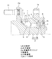
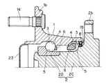
この発明の第1の実施形態を図1ないし図6と共に説明する。この実施形態は内輪回転タイプで従動輪支持用の車輪用軸受装置であり、第3世代に分類されるものである。この車輪用軸受装置は、内周に複列の軌道面4を有する外方部材1と、これら軌道面4にそれぞれ対向する軌道面5を有する内方部材2と、これら複列の軌道面4,5間に介在する複列の転動体3とを備える。転動体3はボールからなり、各列毎に保持器6で保持されている。この車輪用軸受装置は、複列のアンギュラ玉軸受とされ、各軌道面4,5は、断面円弧状とされて接触角が背面合わせとなるように形成されている。
【0015】
外方部材1は、固定側の部材となるものであって、車体取付フランジ1aを有する一体の部材である。内方部材2は、回転側の部材となるものであって、車輪取付フランジ2aを有するハブ輪2Aと、このハブ輪2Aの端部外径に嵌合した別体の内輪構成部材2Bとで構成され、ハブ輪2Aおよび内輪構成部材2Bに各列の軌道面5,5がそれぞれ形成される。車輪取付フランジ2aは内方部材2の一端に位置して、外方部材1の円筒部の外径面よりも外径側に突出するように形成されている。車輪取付フランジ2aには、車輪(図示せず)がボルト14で取付けられる。内輪構成部材2Bは、ハブ輪2Aに設けられた加締部でハブ輪2Aに軸方向に締め付け固定される。内外の部材2,1間に形成される環状空間の両側の開口端部は、それぞれリップ付きのシール部材7,8で密封されている。
【0016】
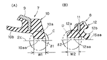
図2(A)に拡大断面図で示すように、一方(アウトボード側)のシール部材7は、円周部9aと立板部9bとでなる断面L字状の芯金9と、この芯金9に固着された弾性部材10とで構成される。このシール部材7は、芯金9の円周部9aを外方部材1の内径面に嵌合することで、外方部材1に取付けられている。弾性部材10には、内方部材2の外周の上記車輪取付フランジ2aの近傍におけるシール面2cに先端が向かう3つのシールリップ10a,10b,10cが形成されている。そのうち、内外の部材2,1の間の軸受空間に対する最内側のシールリップ10aを除く各シールリップ10b,10cはそれらの先端が軸受空間の外側へ延びるように形成され、上記シール面2cに対して接触している。
最内側のシールリップ10aは、先端が軸受空間の内側に延びるように形成され、図2(B)に拡大断面図で示すように、先端とシール面2cとの間に隙間δ1を生じる非接触シールリップとされている。隙間δ1は径方向に生じたものとされ、気体の漏れが可能で、かつ相対回転により非接触シール効果が得られる程度の大きさとされている。シールリップ10aの先端面10aaは、軸受内側に至るに従って隙間δ1の寸法が大きくなるテーパ面ないし湾曲面とされている。なお、図2(B)において、隙間δ1は、先端面10aaとシール面2cとの間の隙間のうち、最小寸法となる部分から寸方を引き出して示しているが、隙間δ1は、シールリップ10aの先端面10aaとシール面2cとの間の空間の全体を言う。
【0017】
図3(A)に拡大断面図で示すように、他方(インボード側)のシール部材8は、円周部11aと立板部11bとでなる断面L字状の芯金11と、この芯金11に装着された弾性部材12とで構成される。シール部材8は、芯金11の円周部11aを外方部材1の内径面に嵌合させることで、外方部材1に取付けられている。シール部材8に対向して、シール接触部材15が設けられている。シール接触部材15はスリンガとなるものであり、円周部15aと立板部15bとでなる断面L字状のものとされ、円周部15aで内方部材2の外周に嵌合して取付けられている。
シール部材8の弾性部材12は、シール接触部材15のL字の内側の面からなるシール面15aa,15baに先端が向かう3つのシールリップ12a,12b,12cが形成されている。そのうち、軸受空間に対する最内側のシールリップ12aを除く各シールリップ12b,12cは、上記シール面15aa,15baにそれぞれ対して接触させてある。最内側のシールリップ12aは、その一部を図3(B)に拡大断面図で示すように、先端とシール接触部材15のシール面15aaとの間に、径方向の隙間δ2を生じる非常接触シールリップとされている。この隙間δ2は、気体の漏れが可能で、かつ相対回転により非接触効果が得られる程度の大きさとされている。シールリップ12aは、先端が軸受空間の内側へ延びるものとされている。シールリップ12aの先端面12aaは、軸受内側に至るに従って隙間δ2の寸法が大きくなるテーパ面ないし湾曲面とされている。図3(B)においても、隙間δ2は、先端面12aaとシール面15aaとの間の隙間のうち、最小寸法となる部分から寸方を引き出して示しているが、隙間δ2は、シールリップ12aの先端面12aaとシール面15aaとの間の空間の全体を言う。
【0018】
この構成の車輪用軸受装置において、アウトボード側のシール部材7は、複数のシールリップ10a〜10cのうち、最内側のシールリップ10aを非接触シールとしたため、このシールリップ10aについて摩擦抵抗が生じず、シール部材7によるトルクロスの発生が軽減される。最内側のシールリップ10aは、封入潤滑剤の漏れ防止を行うものであり、非接触シールであっても、隙間δ1がある程度小さければ、グリース等の粘性のある潤滑剤は流出せず、潤滑剤の漏れ防止機能が確保される。また、非接触シールとしたため、軸受運転時の発熱により、軸受空間の空気が膨張しても、外部に出される。そのため、最内側のシールリップ10aが空気圧でシール面に押し付けられることが防止され、摩擦抵抗の増大が生じない。外部からの塵埃,泥水の侵入については、他の接触式のシールリップ10b,10cにより防止される。
【0019】
上記と同様にインボード側のシール部材8においても、最内側のシールリップ12aを非接触シールとしたため、このシールリップ12aについて摩擦抵抗が生じず、トルクロスの発生が軽減される。最内側のシールリップ12aは、封入潤滑剤の漏れ防止を行うものであり、非接触シールであっても、隙間δ2がある程度小さければ、グリース等の粘性のある潤滑剤は流出せず、潤滑剤の漏れ防止機能が確保される。また、非接触シールとしたため、軸受運転時の発熱により、軸受空間の空気が膨張しても、外部に出される。そのため、最内側のシールリップ12aが空気圧でシール面に押し付けられることが防止され、摩擦抵抗の増大が生じない。外部からの塵埃,泥水の侵入については、他の接触式のシールリップ12b,12cにより防止される。
なお、軸受空間のグリースは、一般的にはシール側より封入するが、例えば外方部材1に注入孔(図示せず)等を設け、ボール3,3間から封入するようにすると、さらにグリースが漏れ難くなる。
【0020】
上記実施形態において、シール部材7,8のシールリップ10a,12aは非接触シールリップであり、その先端形状が接触抵抗に影響を与えることはないので、これらの先端部をさらに厚くしたり薄くしてもよい。
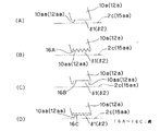
例えば図4(A),(B)に示すように、これらシールリップ10a,12aにおけるシール面2c,15aaと対面する先端面10aa,12aaの厚み幅W1,W2を、他のシールリップ10b,10c,12b,12cの先端面の厚み幅よりも広くしても良い。
【0021】
また、図4(A),(B)のC部,D部を拡大して図5(A)に示すが、同図のように、これらシールリップ10a,12aの先端の厚み幅W1,W2を広くした場合に、先端面10aa,12aaを平坦面とするのに代えて、その先端面10aa,12aaに、図5(B)〜(D)のように環状の溝16A,16B,16Cを形成しても良い。図5(B),(D)は環状の溝16A,16Cを2列以上とした例であり、このうち、同図(B)は溝16Aの断面形状をV字状として各溝16Aが略隣接して続くように形成したものである。同図(D)は、複数の溝16Cを離して形成した例であり、溝断面形状は例えばU字状とされている。同図(C)の例は、環状の溝16Bが1条であって、その溝幅が厚み幅W1,W2の大部分を占めるように形成したものである。これらの各例のように、環状の溝16A,16B,16Cを形成した場合は、隙間δ1,δ2がラビリンス構造となり、シール性がより一層向上する。また、図5(B),(D)のように複数の溝16A,16Cを設けた場合は、隙間δ1,δ2がより複雑なラビリンス構造となり、シール性がより一層向上する。
【0022】
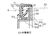
また、上記実施形態において、図6に示すように、シール接触部材15の立板部15bにおける軸受空間の外側に向く側面に、円周方向に磁極が交互に着磁されたリング状の多極磁石20を設けても良い。この多極磁石20とシール接触部材15とで磁気エンコーダ21を構成する。多極磁石20は、例えば磁性体粉の混入されたゴム磁石、プラスチッチ磁石、または焼結磁石からなる。この磁気エンコーダ21にアキシアル方向から対面してセンサ22を配置することにより、車輪回転数を検出する回転数検出装置をコンパクトに構成することができる。
【0023】
図7〜図11は、それぞれこの発明における他の各実施形態を示す。これらの各実施形態は、第1の実施形態と世代の異なる形式の車輪用軸受装置に適用した例を示す。これら各実施形態も、第1の実施形態と同様に、内周に複列の軌道面4を有する外方部材1と、これら軌道面4にそれぞれ対向する軌道面5を有する内方部材2と、前記各軌道面4,5間に介在する複列の転動体3とを備え、車体に対して車輪を回転自在に支持する車輪用軸受装置である。これらの実施形態は、特に説明した事項を除き、第1の実施形態と同じ構成である。
【0024】
図7は第2の実施形態を示す。この車輪用軸受装置は、第3世代の内輪回転タイプで、かつ駆動輪支持用とした例である。
この実施形態は、駆動輪用であるため、図1に示す第1の実施形態において、内方部材2を構成するハブ輪2Aに、等速ジョイント(図示せず)の軸部が挿通されて固定される内径孔2dが形成されている。内外の部材2,1間の端部環状空間を密封するリップ付きのシール部材7,8が設けられていること、これらシール部材7,8の構成、およびその他の構成は図1に示す第1の実施形態と同じである。
【0025】
図8は第3の実施形態を示す。この車輪用軸受装置は、第3世代の外輪回転タイプで、かつ従動輪支持用とした例である。この実施形態の場合、外方部材1に車輪取付フランジ1bが一体形成されている。内方部材2は、車体取付フランジ2bが一体形成された第1の内輪構成部材2Cと、第2の内輪構成部材2Dとを組み合わせたものとされており、これら内輪構成部材2C,2Dに各列の軌道面5が形成されている。外方部材1のアウトボード側の端部開口はキャップ23で覆われている。このキャップ23があるために、内外の部材2,1の間の端部環状空間のうち、アウトボード側の端部にはシール部材は設けられておらず、インボード側の端部にのみリップ付きシール部材8が設けられている。シール部材8およびその他の構成は、第1の実施形態と同じである。
【0026】
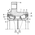
図9は第4の実施形態を示す。この車輪用軸受装置は、第1世代の例であり、内周に複列の溝状の軌道面4を有する外方部材1と、これら軌道面4にそれぞれ対向する溝状の軌道面5を有する内方部材2と、これら複列の軌道面4,5間に介在する複列の転動体3とを備える。内方部材2は2つの軸受内輪2Eを軸方向に並べた分割型のものである。転動体3は円錐ころからなり、各列毎に保持器6で保持されている。内外の部材2,1間に形成される環状空間の両端部には、シール部材8およびこれに対向するシール接触部材15がそれぞれ設けられている。両シール部材8およびシール接触部材15は、第1の実施形態で説明したものである。
【0027】
図10は第5の実施形態を示す。この車輪用軸受装置は、第2世代の内輪回転タイプで、かつ従動輪支持用としたものである。
この実施形態の場合、外方部材1は車体取付フランジ1aを有する。その他の構成は図9に示す第4の実施形態と同じである。
【0028】
図11は第6の実施形態を示す。この車輪用軸受装置は、第2世代の外輪回転タイプで、かつ従動輪支持用の車輪用軸受装置である。
この実施形態の場合、外方部材1は車輪取付フランジ1bを有する。分割型の内方部材2は、軸方向に並べた2つの軸受内輪2Eが連結環24で連結されている。その他の構成は図9に示す第4の実施形態と同じである。
【0029】
なお、この発明は、転動体3の形式を問わずに適用でき、例えば上記各実施形態において、アンギュラ玉軸受形式とした各例を円すいころ軸受形式としても、また円すいころ軸受形式とした各例をアンギュラ玉軸受形式としても良い。
【0030】
【発明の効果】
この発明の車輪用軸受装置は、シール部材が複数のシールリップを有し、これら複数のシールリップのうち、軸受空間に対する最内側のシールリップを非接触シールとし、他のシールリップを接触シールとしたため、封入潤滑剤の漏れ防止、および外部からの塵埃,泥水の侵入防止効果を確保しながら、摩擦抵抗を低減でき、それだけトルクロスを少なくすることができる。シール接触部材を設け、このシール接触部材に、円周方向に磁極が交互に着磁されたリング状の多極磁石を設けた場合は、対面してセンサを配置することにより、車輪回転数を検出することができる。またシール接触部材に多極磁石を設けるので、別部材の多極磁石を車輪用軸受装置に取付けることが不要となる。
【図面の簡単な説明】
【図1】この発明の第1の実施形態にかかる車輪用軸受装置の断面図である。
【図2】(A)は同車輪用軸受装置における一方のシール部材の拡大断面図、(B)は(A)におけるA部の拡大図である。
【図3】(A)は同車輪用軸受装置における他方のシール部材の拡大断面図、(B)は(A)におけるB部の拡大図である。
【図4】(A)は一方のシール部材の変形例の要部拡大断面図、(B)は他方のシール部材の変形例の要部拡大断面図である。
【図5】図4のシール部材における非接触シールリップの先端面の各変形例を示す断面図である。
【図6】他方のシール部材の他の変形例を示す拡大断面図である。
【図7】この発明の第2の実施形態にかかる車輪用軸受装置の断面図である。
【図8】この発明の第3の実施形態にかかる車輪用軸受装置の断面図である。
【図9】この発明の第4の実施形態にかかる車輪用軸受装置の断面図である。
【図10】この発明の第5の実施形態にかかる車輪用軸受装置の断面図である。
【図11】この発明の第6の実施形態にかかる車輪用軸受装置の断面図である。
【図12】従来例の断面図である。
【図13】(A)は従来例における一方のシール部材の拡大断面図、(B)は従来例における他方のシール部材の拡大断面図である。
【符号の説明】
1…外方部材
2…内方部材
2a…車輪取付フランジ
2c…シール面
3…転動体
4,5…軌道面
7,8…シール部材
9…芯金
10…弾性部材
10a〜10c…シールリップ
11…芯金
12…弾性部材
12a〜12c…シールリップ
15…シール接触部材
15a…円周部
15b…立板部
15aa,15ba…シール面
16A〜16C…溝
20…多極磁石
δ1,δ2…隙間[0001]
BACKGROUND OF THE INVENTION
The present invention relates to a wheel bearing device in an automobile or the like, and more particularly to a sealing structure thereof.
[0002]
[Prior art]
Bearing devices used in vehicles such as automobiles are in a harsh environment where they are exposed to road surfaces, etc., so it is necessary to prevent dust and muddy water from entering the system from the outside. A high effect is also required for prevention of the above.
For this reason, for example, a seal structure as shown in FIGS. 12 and 13 is employed. The bearing device shown in FIG. 1 has an annular space formed between inner and
[0003]
The E part of FIG. 12 is expanded and shown to FIG. 13 (A). The
[0004]
The F part of FIG. 12 is expanded and shown to FIG. 13 (B). The inboard-
According to the
[0005]
[Problems to be solved by the invention]
However, since each of the
[0006]
In a vehicle, there is a demand for weight reduction and low friction resistance for a wheel bearing device in order to reduce fuel consumption. The major factors of the friction resistance in the bearing are the preload and the seal torque, and the torque by the contact seal largely governs the friction resistance in the wheel bearing device.
[0007]
An object of the present invention is to provide a wheel bearing device that can reduce frictional resistance while preventing leakage of encapsulated lubricant and preventing dust and muddy water from entering from the outside.
[0008]
[Means for Solving the Problems]
A wheel bearing device according to a first aspect of the present invention includes an outer member having a double-row raceway surface on an inner periphery, an inner member having a raceway surface facing each of the raceway surfaces, and the double-row raceway. A wheel bearing device comprising: a double row rolling element interposed between surfaces; and a seal member that seals an end annular space on the outboard side between the outer member and the inner member. The member is composed of a hub wheel having a wheel mounting flange and a separate inner ring constituent member fitted to the outer diameter of the end of the hub wheel, and the hub wheel has an outer peripheral surface portion in the vicinity of the wheel mounting flange. A concave curved seal surface, wherein the outboard-side seal member is attached to the outer member, and is a concave curved seal surface that is an outer peripheral surface portion in the vicinity of the wheel mounting flange of the hub wheel. And a seal on the outer peripheral surface of the hub wheel Have tips three sealing lips towards within, among these three sealing lips, the innermost seal lip with respect to the bearing space, between the tip and the sealing surface, the relative rotationPrevent grease from flowing out of bearing spaceNon-contact sealing effectIt is obtained and gas can be leaked, and even if the air in the bearing space expands due to heat generated during bearing operation, it is prevented from being pressed against the sealing surface by air pressure.A non-contact seal lip that creates a gap is formed, the other two seal lips are brought into contact with the concave curved seal surface, and the innermost non-contact seal lip has its tip and a seal surface facing the tip. Assuming that a uniform radial clearance is formed around the entire circumference of the circumferential portion, and that the tip extends to the inside of the bearing space, the clearance gap increases as the tip surface of the non-contact seal lip reaches the inside of the bearing. The other two seal lips of the three seal lips are formed so that their tips extend outside the bearing space.
According to a second aspect of the present invention, there is provided a wheel bearing device comprising: an outer member having a double row raceway surface on an inner periphery; an inner member having a raceway surface facing each of the raceway surfaces; and the double row raceway. A wheel bearing device comprising: a double row rolling element interposed between surfaces; and a seal member that seals an end annular space on the outboard side between the outer member and the inner member. The member is composed of a hub wheel having a wheel mounting flange and a separate inner ring constituent member fitted to the outer diameter of the end of the hub wheel, and the hub wheel has an outer peripheral surface portion in the vicinity of the wheel mounting flange. A concave curved seal surface, wherein the outboard-side seal member is attached to the outer member, and is a concave curved seal surface that is an outer peripheral surface portion in the vicinity of the wheel mounting flange of the hub wheel. , And the outer peripheral surface of the hub wheel Has three sealing lips tip towards Lumpur surface, among these three sealing lips, the innermost seal lip with respect to the bearing space, between the tip and the sealing surface, the relative rotationPrevent grease from flowing out of bearing spaceNon-contact sealing effectIt is obtained and gas can be leaked, and even if the air in the bearing space expands due to heat generated during bearing operation, it is prevented from being pressed against the sealing surface by air pressure.A non-contact seal lip that creates a gap is formed, the other two seal lips are brought into contact with the concave curved seal surface, and the innermost non-contact seal lip has its tip and a seal surface facing the tip. It is assumed that a uniform radial clearance is formed around the entire circumference of the circumferential portion, and the tip extends to the inside of the bearing space. The thickness width of the tip surface of this non-contact seal lip is set to each of the other seal lips. The other two seal lips of the three seal lips are formed so that their tips extend outside the bearing space.
According to a third aspect of the present invention, there is provided a wheel bearing device according to the first aspect, further comprising: a sealing member that seals the end annular space on the inboard side between the outer member and the inner member; A board-side seal member is attached to the outer member, and has three seal lips whose front ends are directed to a seal surface of a seal contact member attached to the inner member. Of these three seal lips, a bearing The innermost seal lip with respect to the space is moved between the tip and the seal surface by relative rotation.Prevent grease from flowing out of bearing spaceNon-contact sealing effectIt is obtained and gas can be leaked, and even if the air in the bearing space expands due to heat generated during bearing operation, it is prevented from being pressed against the sealing surface by air pressure.A non-contact seal lip that generates a gap is formed, and the other two seal lips are brought into contact with the seal surface. The innermost seal lip has a tip end and a seal surface portion facing the tip end in the circumferential direction. The tip of the non-contact seal lip is tapered so that the gap increases toward the inner side of the bearing, and a uniform radial clearance is generated around the entire circumference of the bearing. The inboard side seal member is composed of a core bar having an L-shaped cross section composed of a circumferential portion and a standing plate portion, and an elastic member attached to the core bar, and each seal lip is formed on the elastic member. The seal contact member has an L-shaped cross section composed of a cylindrical portion and a standing plate portion, and the innermost seal lip of the seal member with a lip is formed from the L-shaped inner surface of the seal contact member. Na Is opposed to the portion of the cylindrical surface of the sealing surface, of the other seal lip of the sealing surface of the sealing contact member at least one sealing lip, it is obtained by contacting the portion of the standing portion.
According to a fourth aspect of the present invention, there is provided a wheel bearing device according to the first aspect, further comprising: a seal member that seals the end annular space on the inboard side between the outer member and the inner member; A board-side seal member is attached to the outer member, and has three seal lips whose front ends are directed to a seal surface of a seal contact member attached to the inner member. Of these three seal lips, a bearing The innermost seal lip with respect to the space is moved between the tip and the seal surface by relative rotation.Prevent grease from flowing out of bearing spaceNon-contact sealing effect obtainedIn addition, even if the air in the bearing space expands due to heat generated during the operation of the bearing, it can be prevented from being pressed against the sealing surface by air pressure.A non-contact seal lip that generates a gap is formed, and the other two seal lips are brought into contact with the seal surface. The innermost seal lip has a tip end and a seal surface portion facing the tip end in the circumferential direction. It is assumed that a uniform radial clearance is generated around the entire circumference of the shaft, and the tip extends to the inside of the bearing space. The thickness width of the tip surface of this non-contact seal lip is the thickness width of the tip surface of each other seal lip. The inboard seal member is made up of an L-shaped cored bar composed of a circumferential part and a standing plate part, and an elastic member mounted on the cored bar. Each seal lip is formed, the seal contact member has an L-shaped cross section composed of a cylindrical portion and a standing plate portion, and the innermost seal lip in the seal member with the lip is L of the seal contact member. From the inner surface of the letter It is opposed to the portion of the cylindrical surface of the that the sealing surface, of the other seal lip of the sealing surface of the sealing contact member at least one sealing lip, is obtained by contacting the portion of the standing portion.
According to a fifth aspect of the present invention, there is provided a wheel bearing device according to the second aspect, further comprising: a seal member that seals the end annular space on the inboard side between the outer member and the inner member. A board-side seal member is attached to the outer member, and has three seal lips whose front ends are directed to a seal surface of a seal contact member attached to the inner member. Of these three seal lips, a bearing The innermost seal lip with respect to the space is moved between the tip and the seal surface by relative rotation.Prevent grease from flowing out of bearing spaceNon-contact sealing effect obtainedIn addition, even if the air in the bearing space expands due to heat generated during the operation of the bearing, it can be prevented from being pressed against the sealing surface by air pressure.A non-contact seal lip that generates a gap is formed, and the other two seal lips are brought into contact with the seal surface. The innermost seal lip has a tip end and a seal surface portion facing the tip end in the circumferential direction. The tip of the non-contact seal lip is tapered so that the gap increases toward the inner side of the bearing, and a uniform radial clearance is generated around the entire circumference of the bearing. The inboard side seal member is composed of a core bar having an L-shaped cross section composed of a circumferential portion and a standing plate portion, and an elastic member attached to the core bar, and each seal lip is formed on the elastic member. And
The seal contact member has an L-shaped cross section composed of a cylindrical portion and a standing plate portion, and the innermost seal lip of the seal member with a lip is a seal surface formed of an inner surface of the L shape of the seal contact member. Opposite to the cylindrical surface portion, at least one seal lip of the other seal lips is brought into contact with the upright plate portion of the seal surface of the seal contact member.
According to a sixth aspect of the present invention, there is provided a wheel bearing device according to the second aspect, further comprising: a seal member that seals the end annular space on the inboard side between the outer member and the inner member. A board-side seal member is attached to the outer member, and has three seal lips whose front ends are directed to a seal surface of a seal contact member attached to the inner member. Of these three seal lips, a bearing The innermost seal lip with respect to the space is moved between the tip and the seal surface by relative rotation.Prevent grease from flowing out of bearing spaceNon-contact sealing effect obtainedIn addition, even if the air in the bearing space expands due to heat generated during the operation of the bearing, it can be prevented from being pressed against the sealing surface by air pressure.A non-contact seal lip that generates a gap is formed, and the other two seal lips are brought into contact with the seal surface. The innermost seal lip has a tip end and a seal surface portion facing the tip end in the circumferential direction. It is assumed that a uniform radial clearance is generated around the entire circumference of the shaft, and the tip extends to the inside of the bearing space. The thickness width of the tip surface of this non-contact seal lip is the thickness width of the tip surface of each other seal lip. The inboard seal member is made up of an L-shaped cored bar composed of a circumferential part and a standing plate part, and an elastic member mounted on the cored bar. Each seal lip is formed, the seal contact member has an L-shaped cross section composed of a cylindrical portion and a standing plate portion, and the innermost seal lip in the seal member with the lip is L of the seal contact member. From the inner surface of the letter It is opposed to the portion of the cylindrical surface of the that the sealing surface, of the other seal lip of the sealing surface of the sealing contact member at least one sealing lip, is obtained by contacting the portion of the standing portion.
According to a seventh aspect of the present invention, there is provided a wheel bearing device comprising: an outer member having a double row raceway surface on an inner periphery; an inner member having a raceway surface facing each of the raceway surfaces; and the double row raceway. In a wheel bearing device comprising a double row rolling element interposed between surfaces and a seal member that seals an end annular space between the outer member and the inner member, the seal member includes the outer member. Three seal lips that are attached to one member of the side member and the inner member and that have their tips directed toward the seal surface of the seal contact member attached to the other member, and of these three seal lips, The innermost seal lip with respect to the bearing space is moved by relative rotation between the tip and the seal surface.Prevent grease from flowing out of bearing spaceNon-contact sealing effectIt is obtained and gas can be leaked, and even if the air in the bearing space expands due to heat generated during bearing operation, it is prevented from being pressed against the sealing surface by air pressure.A non-contact seal lip that generates a gap is formed, and the other two seal lips are brought into contact with the seal surface. The innermost seal lip has a tip end and a seal surface portion facing the tip end in the circumferential direction. The tip of the non-contact seal lip is tapered so that the gap increases toward the inside of the bearing. The seal member is composed of a core bar having an L-shaped cross section composed of a circumferential part and a standing plate part, and an elastic member attached to the core bar, and each seal lip is formed on the elastic member. The seal contact member has an L-shaped cross section composed of a cylindrical portion and a standing plate portion, and the innermost seal lip of the seal member with the lip is a seal surface formed by an inner surface of the L shape of the seal contact member of Is opposed to the portion of the Chi cylindrical surface of the other seal lip of the sealing surface of the sealing contact member at least one sealing lip, it is obtained by contacting the portion of the standing portion.
According to an eighth aspect of the present invention, there is provided a wheel bearing device comprising: an outer member having a double row raceway surface on an inner periphery; an inner member having a raceway surface facing each of the raceway surfaces; and the double row raceway. In a wheel bearing device comprising a double row rolling element interposed between surfaces and a seal member that seals an end annular space between the outer member and the inner member, the seal member includes the outer member. Three seal lips that are attached to one member of the side member and the inner member and that have their tips directed toward the seal surface of the seal contact member attached to the other member, and of these three seal lips, The innermost seal lip with respect to the bearing space is moved by relative rotation between the tip and the seal surface.Prevent grease from flowing out of bearing spaceNon-contact sealing effectIt is obtained and gas can be leaked, and even if the air in the bearing space expands due to heat generated during bearing operation, it is prevented from being pressed against the sealing surface by air pressure.A non-contact seal lip is used, and the other two seal lips are brought into contact with the seal surface. The innermost seal lip has a tip end and a seal surface portion facing the tip all around the circumference. The tip end surface of the non-contact seal lip is wider than the thickness width of the tip end surfaces of the other seal lips. The seal member is composed of an L-shaped cored bar composed of a circumferential part and a standing plate part, and an elastic member attached to the cored bar, and each seal lip is formed on the elastic member. The seal contact member has an L-shaped cross section composed of a cylindrical portion and an upright plate portion, and the innermost seal lip of the seal member with a lip is composed of an L-shaped inner surface of the seal contact member. Of the sealing surfaces, the cylindrical surface Min are opposed, among other sealing lip, of the sealing surface of the sealing contact member at least one sealing lip, it is obtained by contacting the portion of the standing portion.
Of the standing plate portion of the core metal in the seal member, most of one surface and the other surface of the distal end portion extending in the radial direction may be sandwiched by the base end portions of the three seal lips.
The seal contact member may be provided with a ring-shaped multipolar magnet having magnetic poles alternately magnetized in the circumferential direction.
The tip surface of the non-contact seal lip is an annular groove having a plurality of V-shaped cross-sectional shapes, a plurality of annular grooves having a U-shaped cross-sectional shape, or a single annular groove, and the groove width thereof It is good also as an annular groove which occupies most of the thickness width of the said front end surface.
According to this configuration, since the innermost seal lip among the plurality of seal lips is a non-contact seal, no frictional resistance is generated with respect to the seal lip, and the occurrence of torque cross due to the seal is reduced. The innermost seal lip prevents leakage of the enclosed lubricant. Even if it is a non-contact seal, if the gap is small enough, viscous lubricants such as grease will not flow out, and lubricant leakage will occur. Prevention function is secured. Moreover, since it is a non-contact seal, even if the air in the bearing space expands due to heat generated during the operation of the bearing, it is discharged to the outside. Therefore, the innermost seal lip is prevented from being pressed against the seal surface by air pressure, and the frictional resistance does not increase. Intrusion of dust and muddy water from the outside is prevented by other contact-type seal lips.
[0009]
In the present invention, the seal member may include a cored bar and an elastic member attached to the cored bar, and each seal lip may be formed on the elastic member.
Since both seal-type seal lips are provided on one elastic member while using both a contact-type seal and a non-contact-type seal, the effect of reducing friction can be obtained without increasing the number of parts. Moreover, since the innermost seal lip is also provided on the elastic member attached to the core metal, it is easy to maintain the accuracy of the gap.
[0010]
The innermost seal lip may have a gap in the radial direction between the tip and the seal surface portion facing the tip. When the gap is generated in the radial direction as described above, unlike the case of generating the gap in the axial direction, the outer surface of the inner member or the inner surface of the outer member is directly opposed to the seal lip. It is possible to add a member for forming a non-contact seal gap and to process a collar part or the like.
Further, the innermost seal lip may have a tip extending inward of the bearing space. Even when the innermost seal lip is made non-contact as described above, it is easy to obtain an appropriate interval between the seal lips, and an improvement in sealing performance can be expected.
[0011]
In the innermost seal lip, the thickness width of the tip surface facing the seal surface may be wider than the thickness width of the tip surfaces of the other seal lips. Since the innermost seal lip is non-contact and does not affect the friction increase, the thickness width of the front end face can be freely widened to enhance the sealing effect. The “thickness width of the tip surface of each of the other seal lips” refers to, for example, the width of the portion that contacts the seal surface.
Further, an annular groove may be formed on the tip surface of the innermost seal lip. Thus, by forming a groove | channel in a front end surface, the said clearance gap becomes a labyrinth structure and a sealing performance improves. Further, the annular grooves may be arranged in two or more rows. In this case, the gap becomes a more complicated labyrinth structure, and the sealing performance is further improved. As described above, since the innermost seal lip can be freely expanded in thickness, the grooves can be easily formed, and the grooves can be formed in multiple rows.
[0012]
Further, in the present invention, the seal contact member is provided, the seal contact member has an L-shaped cross section composed of a cylindrical portion and a standing plate portion, and the innermost seal lip in the seal member with a lip is the seal. Of the sealing surface formed by the inner surface of the L-shape of the contact member, the cylindrical surface portion is opposed to at least one seal lip of the seal contact member. You may make it contact the part of a board part. When such an L-shaped seal contact member is used, the effect of preventing the entry of dust and muddy water from the outside can be further ensured, and the innermost seal lip can also function to prevent the entry of dust and muddy water from the outside. It is unnecessary and there is no problem of lowering the function of preventing the entry of dust and muddy water due to the non-contact seal on the innermost seal lip.
Further, when the seal contact member is provided, a ring-shaped multipolar magnet having magnetic poles alternately magnetized in the circumferential direction may be provided on the seal contact member. When the multipolar magnet is provided in this manner, the rotational speed of the wheel can be detected by arranging the sensors facing each other. Moreover, since the multipolar magnet is provided on the seal contact member, it is not necessary to attach a separate multipolar magnet to the wheel bearing device.
[0013]
Further, in this invention, the inner member has a flange protruding at an outer diameter side from the outer diameter surface of the cylindrical portion of the outer member at one end, and the seal member has the end portion in the vicinity of the flange. It is good also as what seals annular space. For example, the inner member may be constituted by a hub wheel having a wheel mounting flange. In the vicinity of such a flange, the outer diameter surface serving as the sealing surface of the inner member has an inclined surface or a curved cross section, but the innermost seal lip is also non-contacted even in such a sealing surface Thus, the friction reducing effect and the leakage preventing effect of the encapsulated lubricant can be obtained.
[0014]
DETAILED DESCRIPTION OF THE INVENTION
A first embodiment of the present invention will be described with reference to FIGS. This embodiment is a wheel bearing device for supporting a driven wheel of an inner ring rotating type, and is classified as a third generation. The wheel bearing device includes an
[0015]
The
[0016]
As shown in an enlarged cross-sectional view in FIG. 2A, one (outboard side) sealing
The
[0017]
As shown in the enlarged cross-sectional view in FIG. 3A, the other (inboard side) sealing
The
[0018]
In the wheel bearing device having this configuration, since the
[0019]
Similarly to the above, in the
The grease in the bearing space is generally sealed from the seal side. For example, if the
[0020]
In the above embodiment, the
For example, as shown in FIGS. 4A and 4B, the thickness widths W1 and W2 of the front end surfaces 10aa and 12aa facing the seal surfaces 2c and 15aa in the
[0021]
4 (A) and 4 (B) are enlarged and shown in FIG. 5 (A). As shown in FIG. 4, the thickness widths W1 and W2 at the tips of the
[0022]
Moreover, in the said embodiment, as shown in FIG. 6, the ring-shaped multipole by which the magnetic pole was alternately magnetized by the circumferential direction on the side surface which faces the outer side of the bearing space in the standing
[0023]
7 to 11 show other embodiments of the present invention. Each of these embodiments shows an example applied to a wheel bearing device of a different type from the first embodiment. In each of these embodiments, as in the first embodiment, the
[0024]
FIG. 7 shows a second embodiment. This wheel bearing device is an example of a third generation inner ring rotating type and for driving wheel support.
Since this embodiment is for a drive wheel, in the first embodiment shown in FIG. 1, a shaft portion of a constant velocity joint (not shown) is inserted into the
[0025]
FIG. 8 shows a third embodiment. This wheel bearing device is an example of a third generation outer ring rotating type and for supporting a driven wheel. In the case of this embodiment, the
[0026]
FIG. 9 shows a fourth embodiment. This wheel bearing device is an example of the first generation, and includes an
[0027]
FIG. 10 shows a fifth embodiment. This wheel bearing device is a second generation inner ring rotating type and is for supporting a driven wheel.
In the case of this embodiment, the
[0028]
FIG. 11 shows a sixth embodiment. This wheel bearing device is a second-generation outer ring rotation type and is a wheel bearing device for supporting a driven wheel.
In the case of this embodiment, the
[0029]
The present invention can be applied regardless of the type of the rolling
[0030]
【The invention's effect】
In the wheel bearing device of the present invention, the seal member has a plurality of seal lips, and among these seal lips, the innermost seal lip with respect to the bearing space is a non-contact seal, and the other seal lips are contact seals. As a result, the frictional resistance can be reduced and the torcross can be reduced as much as possible while preventing leakage of the enclosed lubricant and preventing dust and muddy water from entering.The When a seal contact member is provided and a ring-shaped multipole magnet with magnetic poles alternately magnetized in the circumferential direction is provided on this seal contact member, the wheel rotation speed can be reduced by arranging the sensors facing each other. Can be detected. Further, since the multipolar magnet is provided on the seal contact member, it is not necessary to attach a separate multipolar magnet to the wheel bearing device.
[Brief description of the drawings]
FIG. 1 is a cross-sectional view of a wheel bearing device according to a first embodiment of the present invention.
2A is an enlarged cross-sectional view of one seal member in the wheel bearing device, and FIG. 2B is an enlarged view of a portion A in FIG.
3A is an enlarged cross-sectional view of the other seal member in the wheel bearing device, and FIG. 3B is an enlarged view of a portion B in FIG.
4A is an enlarged cross-sectional view of a main part of a modification of one seal member, and FIG. 4B is an enlarged cross-sectional view of a main part of a modification of the other seal member.
5 is a cross-sectional view showing modifications of the front end surface of a non-contact seal lip in the seal member of FIG.
FIG. 6 is an enlarged cross-sectional view showing another modification of the other seal member.
FIG. 7 is a cross-sectional view of a wheel bearing device according to a second embodiment of the present invention.
FIG. 8 is a cross-sectional view of a wheel bearing device according to a third embodiment of the present invention.
FIG. 9 is a cross-sectional view of a wheel bearing device according to a fourth embodiment of the present invention.
FIG. 10 is a sectional view of a wheel bearing device according to a fifth embodiment of the present invention.
FIG. 11 is a sectional view of a wheel bearing device according to a sixth embodiment of the present invention.
FIG. 12 is a cross-sectional view of a conventional example.
13A is an enlarged cross-sectional view of one seal member in the conventional example, and FIG. 13B is an enlarged cross-sectional view of the other seal member in the conventional example.
[Explanation of symbols]
1 ... Outer member
2 ... Inward member
2a ... Wheel mounting flange
2c ... Seal surface
3 ... rolling element
4, 5 ... orbital surface
7, 8 ... Sealing member
9 ... Core
10: Elastic member
10a to 10c ... seal lip
11 ... Core
12 ... Elastic member
12a-12c ... Seal lip
15 ... Seal contact member
15a ... Circumference
15b ... Standing plate part
15aa, 15ba ... sealing surface
16A-16C ... groove
20 ... multipolar magnet
δ1, δ2 ... Gap
Claims (10)
上記内方部材は、車輪取付フランジを有するハブ輪と、このハブ輪の端部外径に嵌合した別体の内輪構成部材とで構成され、上記ハブ輪は上記車輪取付フランジの近傍における外周面部分が、凹曲面状のシール面であり、
上記アウトボード側のシール部材が、上記外方部材に取付けられて、上記ハブ輪の上記車輪取付フランジの近傍における外周面部分である凹曲面状のシール面、および上記ハブ輪の外周面状のシール面に先端が向かう3つのシールリップを有し、これら3つのシールリップのうち、軸受空間に対する最内側のシールリップを、先端と上記シール面との間に、相対回転によりグリースの軸受空間からの流出を防止する非接触シール効果が得られかつ気体の漏れが可能で軸受運転時の発熱により軸受空間の空気が膨張しても空気圧により上記シール面に押し付けられることが防止される隙間を生じる非接触シールリップとし、
他の2つのシールリップを上記凹曲面状のシール面に対して接触させ、上記最内側の非接触シールリップは、その先端と、その先端に対向するシール面部分とが円周方向の全周で均等な径方向隙間を生じるものとして、かつ先端が軸受空間の内側へ延びるものとし、
この非接触シールリップの先端面を、軸受内側に至るに従って上記隙間が大きくなるテーパ面とし、上記3つのシールリップのうち上記他の2つのシールリップは、それらの先端が軸受空間の外側へ延びるように形成した車輪用軸受装置。An outer member having a double-row raceway surface on the inner periphery, an inner member having a raceway surface facing each of the raceway surfaces, a double-row rolling element interposed between the double-row raceway surfaces, and the outer In a wheel bearing device comprising a seal member that seals an end annular space on the outboard side between a side member and an inward member,
The inner member includes a hub wheel having a wheel mounting flange and a separate inner ring component member fitted to the outer diameter of the end of the hub wheel, and the hub wheel has an outer periphery in the vicinity of the wheel mounting flange. The surface part is a concave curved seal surface,
A seal member on the outboard side is attached to the outer member, and has a concave curved seal surface that is an outer peripheral surface portion in the vicinity of the wheel mounting flange of the hub wheel, and an outer peripheral surface shape of the hub wheel. The seal surface has three seal lips facing the tip, and of these three seal lips, the innermost seal lip with respect to the bearing space is moved from the bearing space of the grease by relative rotation between the tip and the seal surface. a gap non-contact sealing effect for preventing outflow is prevented from being pressed to the seal surface by the air pressure be expanded air bearing space by the heat generated during operation bearing may leak of the resulting Re and gas The resulting non-contact sealing lip,
The other two seal lips are brought into contact with the concave curved seal surface, and the innermost non-contact seal lip has the tip and the seal surface portion facing the tip all around the circumference. Assuming that a uniform radial clearance is produced, and that the tip extends inside the bearing space,
The tip surface of the non-contact seal lip is a tapered surface in which the gap increases toward the inside of the bearing. Of the three seal lips, the other two seal lips have their tips extending outside the bearing space. Wheel bearing device formed as described above.
上記内方部材は、車輪取付フランジを有するハブ輪と、このハブ輪の端部外径に嵌合した別体の内輪構成部材とで構成され、上記ハブ輪は上記車輪取付フランジの近傍における外周面部分が、凹曲面状のシール面であり、
上記アウトボード側のシール部材が、上記外方部材に取付けられて、上記ハブ輪の上記車輪取付フランジの近傍における外周面部分である凹曲面状のシール面、および上記ハブ輪の外周面状のシール面に先端が向かう3つのシールリップを有し、これら3つのシールリップのうち、軸受空間に対する最内側のシールリップを、先端と上記シール面との間に、相対回転によりグリースの軸受空間からの流出を防止する非接触シール効果が得られかつ気体の漏れが可能で軸受運転時の発熱により軸受空間の空気が膨張しても空気圧により上記シール面に押し付けられることが防止される隙間を生じる非接触シールリップとし、
他の2つのシールリップを上記凹曲面状のシール面に対して接触させ、上記最内側の非接触シールリップは、その先端と、その先端に対向するシール面部分とが円周方向の全周で均等な径方向隙間を生じるものとして、かつ先端が軸受空間の内側へ延びるものとし、
この非接触シールリップの先端面の厚み幅を、他の各シールリップの先端面の厚み幅よりも広くし、上記3つのシールリップのうち上記他の2つのシールリップは、それらの先端が軸受空間の外側へ延びるように形成した車輪用軸受装置。An outer member having a double-row raceway surface on the inner periphery, an inner member having a raceway surface facing each of the raceway surfaces, a double-row rolling element interposed between the double-row raceway surfaces, and the outer In a wheel bearing device comprising a seal member that seals an end annular space on the outboard side between a side member and an inward member,
The inner member includes a hub wheel having a wheel mounting flange and a separate inner ring component member fitted to the outer diameter of the end of the hub wheel, and the hub wheel has an outer periphery in the vicinity of the wheel mounting flange. The surface part is a concave curved seal surface,
A seal member on the outboard side is attached to the outer member, and has a concave curved seal surface that is an outer peripheral surface portion in the vicinity of the wheel mounting flange of the hub wheel, and an outer peripheral surface shape of the hub wheel. The seal surface has three seal lips facing the tip, and of these three seal lips, the innermost seal lip with respect to the bearing space is moved from the bearing space of the grease by relative rotation between the tip and the seal surface. Provides a non-contact sealing effect that prevents the outflow of gas and allows gas to leak, and even if the air in the bearing space expands due to heat generation during bearing operation, a gap is created that prevents the air from being pressed against the sealing surface by air pressure. Non-contact seal lip,
The other two seal lips are brought into contact with the concave curved seal surface, and the innermost non-contact seal lip has the tip and the seal surface portion facing the tip all around the circumference. Assuming that a uniform radial clearance is produced, and that the tip extends inside the bearing space,
The thickness width of the tip surface of the non-contact seal lip is made wider than the thickness width of the tip surface of each of the other seal lips, and the other two seal lips of the three seal lips have their tips at the bearings. A wheel bearing device formed to extend to the outside of the space.
上記インボード側のシール部材が、上記外方部材に取付けられて、内方部材に取付けられたシール接触部材のシール面に先端が向かう3つのシールリップを有し、これら3つのシールリップのうち、軸受空間に対する最内側のシールリップを、先端と上記シール面との間に、相対回転によりグリースの軸受空間からの流出を防止する非接触シール効果が得られかつ軸受運転時の発熱により軸受空間の空気が膨張しても空気圧により上記シール面に押し付けられることが防止される隙間を生じる非接触シールリップとし、他の2つのシールリップを上記シール面に対して接触させ、
上記最内側のシールリップは、その先端と、その先端に対向するシール面部分とが円周方向の全周で均等な径方向隙間を生じるものとしてかつ先端が軸受空間の内側へ延びるものとし、この非接触シールリップの先端面を、軸受内側に至るに従って上記隙間が大きくなるテーパ面とし、
上記インボード側のシール部材は、円周部と立板部とでなる断面L字状の芯金と、この芯金に装着された弾性部材とからなり、この弾性部材に各シールリップが形成されたものであり、
上記シール接触部材を円筒部と立板部とでなる断面L字状とし、上記リップ付きシール部材における最内側のシールリップを、上記シール接触部材のL字の内側の面からなるシール面のうち円筒面の部分に対向させ、他のシールリップのうち、少なくとも一つのシールリップを上記シール接触部材のシール面のうち、上記立板部の部分に接触させた車輪用軸受装置。The seal member for sealing an end annular space on the inboard side between the outer member and the inner member according to claim 1,
The inboard-side seal member is attached to the outer member, and has three seal lips whose tip faces the seal surface of the seal contact member attached to the inner member. The innermost seal lip with respect to the bearing space has a non-contact sealing effect that prevents the grease from flowing out of the bearing space by relative rotation between the tip and the sealing surface, and the bearing space is heated by heat generated during bearing operation. A non-contact seal lip that creates a gap that is prevented from being pressed against the seal surface by air pressure even if the air of the air expands , and the other two seal lips are brought into contact with the seal surface,
The innermost seal lip is assumed that the tip and the seal surface portion facing the tip create a uniform radial clearance on the entire circumference, and the tip extends to the inside of the bearing space. The tip surface of this non-contact seal lip is a tapered surface where the gap increases as it reaches the inside of the bearing,
The inboard-side seal member is composed of a core bar having an L-shaped cross section composed of a circumferential part and a standing plate part, and an elastic member mounted on the core bar, and each seal lip is formed on the elastic member. It has been
The seal contact member has an L-shaped cross section composed of a cylindrical portion and a standing plate portion, and the innermost seal lip of the seal member with a lip is a seal surface formed of an inner surface of the L shape of the seal contact member. A wheel bearing device in which a cylindrical surface portion is opposed and at least one of the other seal lips is in contact with the vertical plate portion of the seal surface of the seal contact member.
上記インボード側のシール部材が、上記外方部材に取付けられて、内方部材に取付けられたシール接触部材のシール面に先端が向かう3つのシールリップを有し、これら3つのシールリップのうち、軸受空間に対する最内側のシールリップを、先端と上記シール面との間に、相対回転によりグリースの軸受空間からの流出を防止する非接触シール効果が得られかつ軸受運転時の発熱により軸受空間の空気が膨張しても空気圧により上記シール面に押し付けられることが防止される隙間を生じる非接触シールリップとし、他の2つのシールリップを上記シール面に対して接触させ、上記最内側のシールリップは、その先端と、その先端に対向するシール面部分とが円周方向の全周で均等な径方向隙間を生じるものとして、かつ先端が軸受空間の内側へ延びるものとし、この非接触シールリップの先端面の厚み幅を、他の各シールリップの先端面の厚み幅よりも広くし、
上記インボード側のシール部材は、円周部と立板部とでなる断面L字状の芯金と、この芯金に装着された弾性部材とからなり、この弾性部材に各シールリップが形成されたものであり、
上記シール接触部材を円筒部と立板部とでなる断面L字状とし、上記リップ付きシール部材における最内側のシールリップを、上記シール接触部材のL字の内側の面からなるシール面のうち円筒面の部分に対向させ、他のシールリップのうち、少なくとも一つのシールリップを上記シール接触部材のシール面のうち、上記立板部の部分に接触させた車輪用軸受装置。The seal member for sealing an end annular space on the inboard side between the outer member and the inner member according to claim 1,
The inboard-side seal member is attached to the outer member, and has three seal lips whose tip faces the seal surface of the seal contact member attached to the inner member. bearing the innermost sealing lip for bearing space, between the tip and the seal surface, non-contact sealing effect of preventing the flow out of the bearing space of the grease by relative rotation by heating of the resulting Re and when bearing operation A non-contact seal lip that creates a gap that is prevented from being pressed against the seal surface by air pressure even when the air in the space expands is brought into contact with the other two seal lips against the seal surface, The seal lip assumes that the tip and the seal surface portion facing the tip create a uniform radial clearance over the entire circumference, and the tip is the bearing space. Shall extend to the side, the thickness width of the tip surface of the non-contact seal lip, and wider than the other thickness width of the tip surface of each seal lip,
The inboard-side seal member is composed of a core bar having an L-shaped cross section composed of a circumferential part and a standing plate part, and an elastic member mounted on the core bar, and each seal lip is formed on the elastic member. It has been
The seal contact member has an L-shaped cross section composed of a cylindrical portion and a standing plate portion, and the innermost seal lip of the seal member with a lip is a seal surface formed of an inner surface of the L shape of the seal contact member. A wheel bearing device in which a cylindrical surface portion is opposed and at least one of the other seal lips is in contact with the vertical plate portion of the seal surface of the seal contact member.
上記インボード側のシール部材が、上記外方部材に取付けられて、内方部材に取付けられたシール接触部材のシール面に先端が向かう3つのシールリップを有し、これら3つのシールリップのうち、軸受空間に対する最内側のシールリップを、先端と上記シール面との間に、相対回転によりグリースの軸受空間からの流出を防止する非接触シール効果が得られかつ軸受運転時の発熱により軸受空間の空気が膨張しても空気圧により上記シール面に押し付けられることが防止される隙間を生じる非接触シールリップとし、他の2つのシールリップを上記シール面に対して接触させ、
上記最内側のシールリップは、その先端と、その先端に対向するシール面部分とが円周方向の全周で均等な径方向隙間を生じるものとしてかつ先端が軸受空間の内側へ延びるものとし、この非接触シールリップの先端面を、軸受内側に至るに従って上記隙間が大きくなるテーパ面とし、
上記インボード側のシール部材は、円周部と立板部とでなる断面L字状の芯金と、この芯金に装着された弾性部材とからなり、この弾性部材に各シールリップが形成されたものであり、
上記シール接触部材を円筒部と立板部とでなる断面L字状とし、上記リップ付きシール部材における最内側のシールリップを、上記シール接触部材のL字の内側の面からなるシール面のうち円筒面の部分に対向させ、他のシールリップのうち、少なくとも一つのシールリップを上記シール接触部材のシール面のうち、上記立板部の部分に接触させた車輪用軸受装置。The seal member for sealing the end annular space on the inboard side between the outer member and the inner member according to claim 2,
The inboard-side seal member is attached to the outer member, and has three seal lips whose tip faces the seal surface of the seal contact member attached to the inner member. bearing the innermost sealing lip for bearing space, between the tip and the seal surface, non-contact sealing effect of preventing the flow out of the bearing space of the grease by relative rotation by heating of the resulting Re and when bearing operation A non-contact seal lip that creates a gap that is prevented from being pressed against the seal surface by air pressure even when air in the space expands , and the other two seal lips are brought into contact with the seal surface,
The innermost seal lip is assumed that the tip and the seal surface portion facing the tip create a uniform radial clearance on the entire circumference, and the tip extends to the inside of the bearing space. The tip surface of this non-contact seal lip is a tapered surface where the gap increases as it reaches the inside of the bearing,
The inboard-side seal member is composed of a core bar having an L-shaped cross section composed of a circumferential part and a standing plate part, and an elastic member mounted on the core bar, and each seal lip is formed on the elastic member. It has been
The seal contact member has an L-shaped cross section composed of a cylindrical portion and a standing plate portion, and the innermost seal lip of the seal member with a lip is a seal surface formed of an inner surface of the L shape of the seal contact member. A wheel bearing device in which a cylindrical surface portion is opposed and at least one of the other seal lips is in contact with the vertical plate portion of the seal surface of the seal contact member.
上記インボード側のシール部材が、上記外方部材に取付けられて、内方部材に取付けられたシール接触部材のシール面に先端が向かう3つのシールリップを有し、これら3つのシールリップのうち、軸受空間に対する最内側のシールリップを、先端と上記シール面との間に、相対回転によりグリースの軸受空間からの流出を防止する非接触シール効果が得られかつ軸受運転時の発熱により軸受空間の空気が膨張しても空気圧により上記シール面に押し付けられることが防止される隙間を生じる非接触シールリップとし、他の2つのシールリップを上記シール面に対して接触させ、上記最内側のシールリップは、その先端と、その先端に対向するシール面部分とが円周方向の全周で均等な径方向隙間を生じるものとして、かつ先端が軸受空間の内側へ延びるものとし、この非接触シールリップの先端面の厚み幅を、他の各シールリップの先端面の厚み幅よりも広くし、
上記インボード側のシール部材は、円周部と立板部とでなる断面L字状の芯金と、この芯金に装着された弾性部材とからなり、この弾性部材に各シールリップが形成されたものであり、
上記シール接触部材を円筒部と立板部とでなる断面L字状とし、上記リップ付きシール部材における最内側のシールリップを、上記シール接触部材のL字の内側の面からなるシール面のうち円筒面の部分に対向させ、他のシールリップのうち、少なくとも一つのシールリップを上記シール接触部材のシール面のうち、上記立板部の部分に接触させた車輪用軸受装置。The seal member for sealing the end annular space on the inboard side between the outer member and the inner member according to claim 2,
The inboard-side seal member is attached to the outer member, and has three seal lips whose tip faces the seal surface of the seal contact member attached to the inner member. bearing the innermost sealing lip for bearing space, between the tip and the seal surface, non-contact sealing effect of preventing the flow out of the bearing space of the grease by relative rotation by heating of the resulting Re and when bearing operation A non-contact seal lip that creates a gap that is prevented from being pressed against the seal surface by air pressure even when the air in the space expands is brought into contact with the other two seal lips against the seal surface, The seal lip assumes that the tip and the seal surface portion facing the tip create a uniform radial clearance over the entire circumference, and the tip is the bearing space. Shall extend to the side, the thickness width of the tip surface of the non-contact seal lip, and wider than the other thickness width of the tip surface of each seal lip,
The inboard-side seal member is composed of a core bar having an L-shaped cross section composed of a circumferential part and a standing plate part, and an elastic member mounted on the core bar, and each seal lip is formed on the elastic member. It has been
The seal contact member has an L-shaped cross section composed of a cylindrical portion and a standing plate portion, and the innermost seal lip of the seal member with a lip is a seal surface formed of an inner surface of the L shape of the seal contact member. A wheel bearing device in which a cylindrical surface portion is opposed and at least one of the other seal lips is in contact with the vertical plate portion of the seal surface of the seal contact member.
上記シール部材が、上記外方部材および内方部材のうちの一方の部材に取付けられて、他方の部材に取付けられたシール接触部材のシール面に先端が向かう3つのシールリップを有し、
これら3つのシールリップのうち、軸受空間に対する最内側のシールリップを、先端と上記シール面との間に、相対回転によりグリースの軸受空間からの流出を防止する非接触シール効果が得られかつ気体の漏れが可能で軸受運転時の発熱により軸受空間の空気が膨張しても空気圧により上記シール面に押し付けられることが防止される隙間を生じる非接触シールリップとし、
他の2つのシールリップを上記シール面に対して接触させ、上記最内側のシールリップは、その先端と、その先端に対向するシール面部分とが円周方向の全周で均等な径方向隙間を生じるものとして、かつ先端が軸受空間の内側へ延びるものとし、この非接触シールリップの先端面を、軸受内側に至るに従って上記隙間が大きくなるテーパ面とし、
上記シール部材は、円周部と立板部とでなる断面L字状の芯金と、この芯金に装着された弾性部材とからなり、この弾性部材に各シールリップが形成されたものであり、
上記シール接触部材を円筒部と立板部とでなる断面L字状とし、上記リップ付きシール部材における最内側のシールリップを、上記シール接触部材のL字の内側の面からなるシール面のうち円筒面の部分に対向させ、他のシールリップのうち、少なくとも一つのシールリップを上記シール接触部材のシール面のうち、上記立板部の部分に接触させた車輪用軸受装置。An outer member having a double-row raceway surface on the inner periphery, an inner member having a raceway surface facing each of the raceway surfaces, a double-row rolling element interposed between the double-row raceway surfaces, and the outer In a wheel bearing device comprising a seal member that seals an end annular space between a side member and an inner member,
The seal member is attached to one of the outer member and the inner member, and has three seal lips whose tip faces the seal surface of the seal contact member attached to the other member;
Of these three seal lips, the innermost seal lip with respect to the bearing space has a non-contact sealing effect that prevents the grease from flowing out of the bearing space by the relative rotation between the tip and the sealing surface, and gas. A non-contact seal lip that creates a gap that is prevented from being pressed against the seal surface by air pressure even if air in the bearing space expands due to heat generation during bearing operation ,
The other two seal lips are brought into contact with the seal surface, and the innermost seal lip has a uniform radial clearance between the tip and the seal surface portion opposed to the tip over the entire circumference. And the tip of the non-contact seal lip is a tapered surface in which the gap increases toward the inside of the bearing.
The seal member is composed of a core bar having an L-shaped cross section composed of a circumferential part and a standing plate part, and an elastic member attached to the core bar, and each seal lip is formed on the elastic member. Yes,
The seal contact member has an L-shaped cross section composed of a cylindrical portion and a standing plate portion, and the innermost seal lip of the seal member with a lip is a seal surface formed of an inner surface of the L shape of the seal contact member. A wheel bearing device in which a cylindrical surface portion is opposed and at least one of the other seal lips is in contact with the vertical plate portion of the seal surface of the seal contact member.
上記シール部材が、上記外方部材および内方部材のうちの一方の部材に取付けられて、他方の部材に取付けられたシール接触部材のシール面に先端が向かう3つのシールリップを有し、これら3つのシールリップのうち、軸受空間に対する最内側のシールリップを、先端と上記シール面との間に、相対回転によりグリースの軸受空間からの流出を防止する非接触シール効果が得られかつ気体の漏れが可能で軸受運転時の発熱により軸受空間の空気が膨張しても空気圧により上記シール面に押し付けられることが防止される隙間を生じる非接触シールリップとし、他の2つのシールリップを上記シール面に対して接触させ、
上記最内側のシールリップは、その先端と、その先端に対向するシール面部分とが円周方向の全周で均等な径方向隙間を生じるものとして、かつ先端が軸受空間の内側へ延びるものとし、この非接触シールリップの先端面の厚み幅を、他の各シールリップの先端面の厚み幅よりも広くし、
上記シール部材は、円周部と立板部とでなる断面L字状の芯金と、この芯金に装着された弾性部材とからなり、この弾性部材に各シールリップが形成されたものであり、
上記シール接触部材を円筒部と立板部とでなる断面L字状とし、上記リップ付きシール部材における最内側のシールリップを、上記シール接触部材のL字の内側の面からなるシール面のうち円筒面の部分に対向させ、他のシールリップのうち、少なくとも一つのシールリップを上記シール接触部材のシール面のうち、上記立板部の部分に接触させた車輪用軸受装置。An outer member having a double-row raceway surface on the inner periphery, an inner member having a raceway surface facing each of the raceway surfaces, a double-row rolling element interposed between the double-row raceway surfaces, and the outer In a wheel bearing device comprising a seal member that seals an end annular space between a side member and an inner member,
The seal member has three seal lips that are attached to one of the outer member and the inner member, and that have tip ends directed toward the seal surface of the seal contact member attached to the other member. Of the three seal lips, the innermost seal lip with respect to the bearing space has a non-contact sealing effect that prevents the grease from flowing out of the bearing space by relative rotation between the tip and the sealing surface, and gas A non-contact seal lip that creates a gap that is prevented from being pressed against the seal surface by air pressure even if the air in the bearing space expands due to heat generated during bearing operation , and the other two seal lips are sealed. Touch the surface,
The innermost seal lip is assumed to have a uniform radial clearance between the tip and the seal surface portion facing the tip over the entire circumference, and the tip extends to the inside of the bearing space. The thickness width of the tip surface of this non-contact seal lip is made wider than the thickness width of the tip surface of each other seal lip,
The seal member is composed of a core bar having an L-shaped cross section composed of a circumferential part and a standing plate part, and an elastic member attached to the core bar, and each seal lip is formed on the elastic member. Yes,
The seal contact member has an L-shaped cross section composed of a cylindrical portion and a standing plate portion, and the innermost seal lip of the seal member with a lip is a seal surface formed of an inner surface of the L shape of the seal contact member. A wheel bearing device in which a cylindrical surface portion is opposed and at least one of the other seal lips is in contact with the vertical plate portion of the seal surface of the seal contact member.
Priority Applications (6)
| Application Number | Priority Date | Filing Date | Title |
|---|---|---|---|
| JP2002219426A JP4297658B2 (en) | 2002-07-29 | 2002-07-29 | Wheel bearing device |
| EP03015961.0A EP1387100B2 (en) | 2002-07-29 | 2003-07-14 | Wheel support bearing assembly |
| DE60334181T DE60334181D1 (en) | 2002-07-29 | 2003-07-14 | Radsupport with bearing arrangement |
| US10/621,404 US7380797B2 (en) | 2002-07-29 | 2003-07-18 | Wheel support bearing assembly |
| CNB031498434A CN1329214C (en) | 2002-07-29 | 2003-07-28 | Wheel support bearing assembly |
| US11/978,683 US20080260314A1 (en) | 2002-07-29 | 2007-10-30 | Wheel support bearing assembly |
Applications Claiming Priority (1)
| Application Number | Priority Date | Filing Date | Title |
|---|---|---|---|
| JP2002219426A JP4297658B2 (en) | 2002-07-29 | 2002-07-29 | Wheel bearing device |
Publications (3)
| Publication Number | Publication Date |
|---|---|
| JP2004060751A JP2004060751A (en) | 2004-02-26 |
| JP2004060751A5 JP2004060751A5 (en) | 2005-08-25 |
| JP4297658B2 true JP4297658B2 (en) | 2009-07-15 |
Family
ID=30112895
Family Applications (1)
| Application Number | Title | Priority Date | Filing Date |
|---|---|---|---|
| JP2002219426A Expired - Lifetime JP4297658B2 (en) | 2002-07-29 | 2002-07-29 | Wheel bearing device |
Country Status (5)
| Country | Link |
|---|---|
| US (2) | US7380797B2 (en) |
| EP (1) | EP1387100B2 (en) |
| JP (1) | JP4297658B2 (en) |
| CN (1) | CN1329214C (en) |
| DE (1) | DE60334181D1 (en) |
Families Citing this family (23)
| Publication number | Priority date | Publication date | Assignee | Title |
|---|---|---|---|---|
| JP4297658B2 (en) * | 2002-07-29 | 2009-07-15 | Ntn株式会社 | Wheel bearing device |
| US7901141B2 (en) * | 2005-02-14 | 2011-03-08 | Nsk Ltd. | Hub unit bearing |
| US7191884B2 (en) * | 2005-02-28 | 2007-03-20 | Shimano Inc. | Bicycle hub |
| DE102005012733B4 (en) * | 2005-03-19 | 2016-03-31 | Schaeffler Kg | poetry |
| DE102006047016B4 (en) | 2005-10-04 | 2020-06-04 | Ntn Corp. | Wheel bearing device |
| JP2007100844A (en) * | 2005-10-04 | 2007-04-19 | Ntn Corp | Bearing device for wheel |
| JP4679325B2 (en) * | 2005-10-04 | 2011-04-27 | Ntn株式会社 | Wheel bearing device |
| KR101355715B1 (en) * | 2006-03-20 | 2014-01-24 | 아크티에볼라게트 에스케이에프 | Annular sealing assembly, in particular for wheel hubs |
| US7588372B2 (en) * | 2006-04-13 | 2009-09-15 | Bishop-Wisecarver Corporation | Guide wheel having a bearing for food and beverage applications |
| JP4371429B2 (en) * | 2007-05-29 | 2009-11-25 | Ntn株式会社 | Wheel bearing device |
| DE602007008108D1 (en) * | 2007-11-06 | 2010-09-09 | Corcos Ind S A S Di Externa It | Sealing arrangement for a rotary member |
| JP5134356B2 (en) * | 2007-12-20 | 2013-01-30 | Ntn株式会社 | Wheel bearing device |
| JP5545210B2 (en) * | 2008-05-27 | 2014-07-09 | 日本精工株式会社 | Rolling bearing |
| JP5334287B2 (en) * | 2008-06-25 | 2013-11-06 | 内山工業株式会社 | Bearing seal |
| CN102472389A (en) * | 2009-07-02 | 2012-05-23 | 内山工业株式会社 | Sealing structure for fitting section |
| DE102010045671A1 (en) * | 2010-09-17 | 2012-03-22 | Carl Freudenberg Kg | sealing profile |
| ITTO20120605A1 (en) * | 2012-07-09 | 2014-01-10 | Skf Ab | BEARING-HUB ASSEMBLY UNIT WITH SEALING DEVICE |
| WO2017051886A1 (en) * | 2015-09-25 | 2017-03-30 | Ntn株式会社 | Bearing device for vehicle wheel |
| JP2017145881A (en) * | 2016-02-17 | 2017-08-24 | 内山工業株式会社 | Sealing device |
| JP6673500B2 (en) * | 2016-11-25 | 2020-03-25 | Nok株式会社 | Sealing device and hub bearing |
| JP2018204642A (en) * | 2017-05-31 | 2018-12-27 | 中西金属工業株式会社 | Rotating seal |
| JP2020079619A (en) * | 2018-11-13 | 2020-05-28 | 中西金属工業株式会社 | Rotary seal |
| CN111660078B (en) * | 2020-06-05 | 2021-08-06 | 华东交通大学 | Front section processing equipment of bearing assembly production line |
Family Cites Families (39)
| Publication number | Priority date | Publication date | Assignee | Title |
|---|---|---|---|---|
| US2887331A (en) * | 1956-10-10 | 1959-05-19 | Gen Motors Corp | Closure |
| US3414275A (en) * | 1964-12-21 | 1968-12-03 | Nippon Seiko Kk | Sealed bearing |
| SE320555B (en) * | 1968-11-21 | 1970-02-09 | Forsheda Gummifabrik Ab | |
| US3895814A (en) * | 1971-08-10 | 1975-07-22 | Parker Hannifin Corp | Rotary shaft seal |
| US4505484A (en) * | 1980-03-12 | 1985-03-19 | Nippon Seiko Kabushiki Kaisha | Sealing device for a rolling bearing |
| US4399998A (en) * | 1981-12-28 | 1983-08-23 | The Timken Company | Self-venting seal lip |
| US4556225A (en) * | 1983-04-13 | 1985-12-03 | Chicago Rawhide Mfg. Co. | Reverse lip positive venting seal |
| USRE36304E (en) * | 1983-10-03 | 1999-09-14 | Konica Corporation | Multiplex image reproducing method |
| DE3528961C3 (en) * | 1985-08-13 | 1994-12-22 | Kugelfischer G Schaefer & Co | Shaft or axle bearings with pressure compensation on both sides with sealing rings |
| GB2179408A (en) * | 1985-08-20 | 1987-03-04 | Angus George Co Ltd | Oil seal with pumping action |
| US4655617A (en) * | 1985-10-11 | 1987-04-07 | Koyo Seiko Co., Ltd. | Sealed rolling bearing with a flow reducing grease passage |
| US4799808A (en) * | 1985-12-19 | 1989-01-24 | The Timken Company | Compact seal |
| DE3677172D1 (en) * | 1985-12-19 | 1991-02-28 | Timken Co | POETRY. |
| DE3607535A1 (en) * | 1986-03-07 | 1987-09-10 | Kugelfischer G Schaefer & Co | SEALED ROLLER BEARING |
| DE3616999A1 (en) † | 1986-05-21 | 1987-11-26 | Kugelfischer G Schaefer & Co | Seal, particularly for rolling-contact bearings |
| JPH0686909B2 (en) | 1987-11-23 | 1994-11-02 | ザ ティムケン カンパニー | Small seal |
| JPH06651Y2 (en) * | 1987-11-30 | 1994-01-05 | 光洋精工株式会社 | Rolling bearing sealing device |
| US4822055A (en) * | 1988-05-17 | 1989-04-18 | General Motors Corporation | Unitized bearing seal assembly |
| DE3838824C2 (en) * | 1988-11-17 | 1995-06-08 | Kugelfischer G Schaefer & Co | Seal consisting of several sealing rings |
| FR2671592B1 (en) † | 1991-01-15 | 1993-06-18 | Roulements Soc Nouvelle | BEARING WITH INFORMATION SENSOR. |
| US5129744A (en) * | 1991-06-17 | 1992-07-14 | The Timken Company | Two component bearing seal with bumpers |
| FR2700588B1 (en) * | 1993-01-19 | 1995-02-17 | Roulements Soc Nouvelle | Mounting device with integrated encoder seal. |
| US5553870A (en) * | 1994-02-16 | 1996-09-10 | The Timken Company | Lip seal separating oil and grease |
| DE19503468C1 (en) * | 1995-02-03 | 1996-05-30 | Freudenberg Carl Fa | Rotary seal cooperating with rotation sensor |
| JPH08270662A (en) * | 1995-02-03 | 1996-10-15 | Koyo Seiko Co Ltd | Seal device for bearing |
| US5947611A (en) * | 1996-01-22 | 1999-09-07 | Nsk Ltd. | Rolling bearing unit with tone wheel |
| JPH09287619A (en) * | 1996-02-23 | 1997-11-04 | Nippon Seiko Kk | Rolling bearing unit with sealing device |
| DE19624611A1 (en) * | 1996-06-20 | 1998-01-02 | Freudenberg Carl Fa | Device for sealing an annular gap between a housing and a shaft |
| JP3740219B2 (en) * | 1996-07-05 | 2006-02-01 | 光洋精工株式会社 | Rolling bearing sealing device |
| US5676383A (en) * | 1996-09-10 | 1997-10-14 | Federal-Mogul Corporation | Hydrodynamic low-torque lubricant seal with pumping projections |
| US5722664A (en) * | 1996-09-25 | 1998-03-03 | The Timken Company | Seal with pumping capabilities |
| JPH10252762A (en) * | 1997-03-12 | 1998-09-22 | Nippon Seiko Kk | Sealing device for rolling bearing |
| JPH11257361A (en) * | 1998-01-08 | 1999-09-21 | Nippon Seiko Kk | Sealing device for rolling bearing |
| JPH11334309A (en) † | 1998-05-29 | 1999-12-07 | Ntn Corp | Wheel supporting device and tapered roller bearing fe supporting wheel |
| JP2001233011A (en) * | 2000-02-24 | 2001-08-28 | Ntn Corp | Wheel bearing device |
| JP4128723B2 (en) | 2000-04-10 | 2008-07-30 | Ntn株式会社 | Wheel bearing |
| EP1177959B1 (en) * | 2000-08-01 | 2007-09-12 | Ntn Corporation | Wheel support bearing assembly and anti-skid brake device using the same |
| JP2003222145A (en) | 2002-01-29 | 2003-08-08 | Nsk Ltd | Wheel support rolling bearing unit with seal ring |
| JP4297658B2 (en) * | 2002-07-29 | 2009-07-15 | Ntn株式会社 | Wheel bearing device |
-
2002
- 2002-07-29 JP JP2002219426A patent/JP4297658B2/en not_active Expired - Lifetime
-
2003
- 2003-07-14 EP EP03015961.0A patent/EP1387100B2/en not_active Expired - Lifetime
- 2003-07-14 DE DE60334181T patent/DE60334181D1/en not_active Expired - Lifetime
- 2003-07-18 US US10/621,404 patent/US7380797B2/en not_active Expired - Lifetime
- 2003-07-28 CN CNB031498434A patent/CN1329214C/en not_active Expired - Lifetime
-
2007
- 2007-10-30 US US11/978,683 patent/US20080260314A1/en not_active Abandoned
Also Published As
| Publication number | Publication date |
|---|---|
| EP1387100A3 (en) | 2005-12-07 |
| EP1387100A2 (en) | 2004-02-04 |
| US20080260314A1 (en) | 2008-10-23 |
| CN1329214C (en) | 2007-08-01 |
| US20040017048A1 (en) | 2004-01-29 |
| JP2004060751A (en) | 2004-02-26 |
| CN1482011A (en) | 2004-03-17 |
| US7380797B2 (en) | 2008-06-03 |
| EP1387100B1 (en) | 2010-09-15 |
| EP1387100B2 (en) | 2013-08-28 |
| DE60334181D1 (en) | 2010-10-28 |
Similar Documents
| Publication | Publication Date | Title |
|---|---|---|
| JP4297658B2 (en) | Wheel bearing device | |
| US6573705B1 (en) | Rotating speed sensor unit and wheel bearing assembly carrying the same | |
| US6065879A (en) | Rolling bearing with seal | |
| US6328476B2 (en) | Rolling bearing unit with encoder | |
| CN100420869C (en) | Vehicle bearing device | |
| JP5334287B2 (en) | Bearing seal | |
| JP2007107674A (en) | Sealing device | |
| JP2005147298A (en) | Bearing device for wheel | |
| US7281424B2 (en) | Rotation-support apparatus with rotation sensor device for drive-wheel | |
| JP2015143564A (en) | Wheel support bearing unit with seal | |
| JP2001065704A (en) | Sealing device | |
| JP4735798B2 (en) | Sealing device | |
| JP2002206557A (en) | Bearing device | |
| JP2008144861A (en) | Bearing unit | |
| JP2002206547A (en) | Seal ring and bearing unit with seal ring for wheel | |
| JP2005098387A (en) | Sealing device with sensor, and rolling bearing using the same | |
| JP2002328133A (en) | Bearing for wheel with revolution speed detector | |
| JP5790109B2 (en) | Rolling bearing device | |
| JP2009127668A (en) | Hermetically sealing device | |
| JP2020051597A (en) | Bearing device for wheel | |
| KR20160000724A (en) | Encoder seal assembly and Wheel bearing using the same for vehicle | |
| WO2023189756A1 (en) | Wheel bearing device | |
| JP2019035421A (en) | Hub unit bearing with combination seal ring | |
| JP2007232150A (en) | Seal with encoder and bearing unit | |
| JP2007239772A (en) | Sealing device |
Legal Events
| Date | Code | Title | Description |
|---|---|---|---|
| A521 | Request for written amendment filed |
Free format text: JAPANESE INTERMEDIATE CODE: A523 Effective date: 20050210 |
|
| A621 | Written request for application examination |
Free format text: JAPANESE INTERMEDIATE CODE: A621 Effective date: 20050406 |
|
| A977 | Report on retrieval |
Free format text: JAPANESE INTERMEDIATE CODE: A971007 Effective date: 20070906 |
|
| A131 | Notification of reasons for refusal |
Free format text: JAPANESE INTERMEDIATE CODE: A131 Effective date: 20070918 |
|
| A521 | Request for written amendment filed |
Free format text: JAPANESE INTERMEDIATE CODE: A523 Effective date: 20071119 |
|
| A131 | Notification of reasons for refusal |
Free format text: JAPANESE INTERMEDIATE CODE: A131 Effective date: 20080624 |
|
| A521 | Request for written amendment filed |
Free format text: JAPANESE INTERMEDIATE CODE: A523 Effective date: 20080825 |
|
| A02 | Decision of refusal |
Free format text: JAPANESE INTERMEDIATE CODE: A02 Effective date: 20081216 |
|
| A521 | Request for written amendment filed |
Free format text: JAPANESE INTERMEDIATE CODE: A523 Effective date: 20090216 |
|
| A911 | Transfer to examiner for re-examination before appeal (zenchi) |
Free format text: JAPANESE INTERMEDIATE CODE: A911 Effective date: 20090312 |
|
| TRDD | Decision of grant or rejection written | ||
| A01 | Written decision to grant a patent or to grant a registration (utility model) |
Free format text: JAPANESE INTERMEDIATE CODE: A01 Effective date: 20090414 |
|
| A01 | Written decision to grant a patent or to grant a registration (utility model) |
Free format text: JAPANESE INTERMEDIATE CODE: A01 |
|
| A61 | First payment of annual fees (during grant procedure) |
Free format text: JAPANESE INTERMEDIATE CODE: A61 Effective date: 20090414 |
|
| R150 | Certificate of patent or registration of utility model |
Free format text: JAPANESE INTERMEDIATE CODE: R150 Ref document number: 4297658 Country of ref document: JP Free format text: JAPANESE INTERMEDIATE CODE: R150 |
|
| FPAY | Renewal fee payment (event date is renewal date of database) |
Free format text: PAYMENT UNTIL: 20120424 Year of fee payment: 3 |
|
| FPAY | Renewal fee payment (event date is renewal date of database) |
Free format text: PAYMENT UNTIL: 20130424 Year of fee payment: 4 |
|
| R250 | Receipt of annual fees |
Free format text: JAPANESE INTERMEDIATE CODE: R250 |
|
| FPAY | Renewal fee payment (event date is renewal date of database) |
Free format text: PAYMENT UNTIL: 20130424 Year of fee payment: 4 |
|
| FPAY | Renewal fee payment (event date is renewal date of database) |
Free format text: PAYMENT UNTIL: 20140424 Year of fee payment: 5 |
|
| R250 | Receipt of annual fees |
Free format text: JAPANESE INTERMEDIATE CODE: R250 |
|
| R250 | Receipt of annual fees |
Free format text: JAPANESE INTERMEDIATE CODE: R250 |
|
| R250 | Receipt of annual fees |
Free format text: JAPANESE INTERMEDIATE CODE: R250 |
|
| R250 | Receipt of annual fees |
Free format text: JAPANESE INTERMEDIATE CODE: R250 |
|
| R250 | Receipt of annual fees |
Free format text: JAPANESE INTERMEDIATE CODE: R250 |
|
| R250 | Receipt of annual fees |
Free format text: JAPANESE INTERMEDIATE CODE: R250 |
|
| R250 | Receipt of annual fees |
Free format text: JAPANESE INTERMEDIATE CODE: R250 |
|
| R250 | Receipt of annual fees |
Free format text: JAPANESE INTERMEDIATE CODE: R250 |
|
| R250 | Receipt of annual fees |
Free format text: JAPANESE INTERMEDIATE CODE: R250 |
|
| R250 | Receipt of annual fees |
Free format text: JAPANESE INTERMEDIATE CODE: R250 |
|
| EXPY | Cancellation because of completion of term |