JP4297465B2 - Screw cap for wide mouth container - Google Patents
Screw cap for wide mouth container Download PDFInfo
- Publication number
- JP4297465B2 JP4297465B2 JP36869899A JP36869899A JP4297465B2 JP 4297465 B2 JP4297465 B2 JP 4297465B2 JP 36869899 A JP36869899 A JP 36869899A JP 36869899 A JP36869899 A JP 36869899A JP 4297465 B2 JP4297465 B2 JP 4297465B2
- Authority
- JP
- Japan
- Prior art keywords
- cap
- screw
- mouth
- container
- metal
- Prior art date
- Legal status (The legal status is an assumption and is not a legal conclusion. Google has not performed a legal analysis and makes no representation as to the accuracy of the status listed.)
- Expired - Fee Related
Links
Images

Classifications
-
- B—PERFORMING OPERATIONS; TRANSPORTING
- B65—CONVEYING; PACKING; STORING; HANDLING THIN OR FILAMENTARY MATERIAL
- B65D—CONTAINERS FOR STORAGE OR TRANSPORT OF ARTICLES OR MATERIALS, e.g. BAGS, BARRELS, BOTTLES, BOXES, CANS, CARTONS, CRATES, DRUMS, JARS, TANKS, HOPPERS, FORWARDING CONTAINERS; ACCESSORIES, CLOSURES, OR FITTINGS THEREFOR; PACKAGING ELEMENTS; PACKAGES
- B65D41/00—Caps, e.g. crown caps or crown seals, i.e. members having parts arranged for engagement with the external periphery of a neck or wall defining a pouring opening or discharge aperture; Protective cap-like covers for closure members, e.g. decorative covers of metal foil or paper
- B65D41/32—Caps or cap-like covers with lines of weakness, tearing-strips, tags, or like opening or removal devices, e.g. to facilitate formation of pouring openings
- B65D41/34—Threaded or like caps or cap-like covers provided with tamper elements formed in, or attached to, the closure skirt
- B65D41/3442—Threaded or like caps or cap-like covers provided with tamper elements formed in, or attached to, the closure skirt with rigid bead or projections formed on the tamper element and coacting with bead or projections on the container
- B65D41/3447—Threaded or like caps or cap-like covers provided with tamper elements formed in, or attached to, the closure skirt with rigid bead or projections formed on the tamper element and coacting with bead or projections on the container the tamper element being integrally connected to the closure by means of bridges
Description
【0001】
【発明の属する技術分野】
本発明は、広口容器の口頸部に螺着されるネジキャップに関し、特に、合成樹脂と金属薄板の複合材によるキャップでピルファープルーフ性を備えた広口容器用のネジキャップに関する。
【0002】
【従来の技術】
ガラス瓶やプラスチック容器や金属缶等において、内容物の取出口を大きく開口させた広口(開口部の内径35mm以上)の容器は、従来から食品等の容器として広く使用されており、そのような広口容器では、開口部を密閉するためのキャップとして、リシール(再封鎖)が可能なネジ式の金属製キャップや樹脂製キャップが常用されている。
【0003】
一方、開封後も繰り返し容器を開口・閉鎖できるネジキャップ(スクリューキャップ)では、消費者が購入する前に不正に開封されたかどうかを示すためのピルファープルーフ(タンパーエビデンス)機構として、キャップのスカート部の下方に、破断容易な弱化部を介して、容器の口頸部に係止されるバンド部を形成するということが従来から一般的に行われている。
【0004】
【発明が解決しようとする課題】
ところで、ピルファープルーフ性を備えた広口容器用のネジキャップについて、それが金属製キャップである場合、キャップのスカート部の金属板を変形させてネジを形成しているため、キャップを掴んで回す時の滑り止めとなるキャップ外面の凹凸(ローレット等)を、ネジが形成されないスカート部上端付近にしか付与することができず、しかも、金属製キャップでは大径になると弱化部の破断に大きな力を要するものとなることから、弱化部を破断しながらキャップを取り外す開封の動作がやり難いものとなっている。
【0005】
また、金属製キャップでは、広口容器の容器本体がネジ付き金属缶(リシール缶)である場合、開封後の容器の開口・閉鎖のためにキャップの着脱を繰り返すことで、キャップ側のネジとの摩擦により金属缶の表面に保護被膜として被覆されている塗膜が剥がれて缶の金属面が露出することとなり、そのために缶のネジ部分が汚れて不衛生な感じを与えるものとなる。
【0006】
そのような金属製キャップに対して、樹脂製キャップの場合には、滑り止めのための凹凸をネジの外面側を含むスカート部の全体に付与することができ、しかも、弱化部の破断にそれ程大きな力を要しないものにすることができて、キャップが大径であっても、弱化部を破断しながらの開封動作をやり易いものとすることができる。
【0007】
また、樹脂製キャップでは、容器本体がネジ付き金属缶の場合に、開封後にキャップの着脱を繰り返し行っても、キャップ側の樹脂のネジとの摩擦では、金属缶の表面を被覆する塗膜が剥がれるようなことはないため、缶のネジ部分が汚れるようなことはない。
【0008】
しかしながら、樹脂製キャップでは、金属製キャップと比べてガスバリヤー性(耐気体透過性)が劣り、特に、広口容器のように開口部の面積が大きい場合には、このガスバリヤー性が劣ることによる影響が顕著なものとなって、容器内に密封された内容物の賞味期間が短くなるという欠点がある。
【0009】
この点について、特開平6−122463号には、樹脂製のキャップにガスバリヤー性を持たせるために、頂面の外面側が金属板で内面側が合成樹脂となるように形成された密閉キャップというものが開示されているが、該公報に開示されている密閉キャップは嵌め込み式のスナップキャップであって、ピルファープルーフ性を備えたネジキャップではない。
【0010】
そのような嵌め込み式のスナップキャップでは、ピルファープルーフ性を備えたネジキャップと比べて、キャップと容器本体の係合力が弱いと密封性が劣り、逆に係合力を強くすると開封性が劣るという問題があり、また、キャップ自体がピルファープルーフ性を備えたものでないため、不正使用の防止手段としてキャップの外側をシュリンク包装で密封するような必要が生じて、新たにシュリンク包装する工程や材料が必要になることで製造コストが高くなる。
【0011】
さらに、上記の公報に記載されている密閉キャップでは、容器口部をキャップで密閉するために、天面(頂部)と側壁(スカート部)を形成する軟質合成樹脂とは異なる別の硬質合成樹脂部材により、天面(頂部)外周縁部から下向きに側壁(スカート部)を外側から覆っていることで、軟質合成樹脂部材とは別に硬質合成樹脂部材を製造して、それを軟質合成樹脂部材に嵌め込む工程が必要になることから、製造コストが高くなる。
【0012】
本発明は、上記のような問題の解消を課題とするものであり、具体的には、ピルファープルーフ性を備えた広口容器用のネジキャップについて、開封し易く、ガスバリヤー性に優れ、しかも、簡単に製造することができて、さらに、容器本体が金属缶であっても、開封後のキャップの着脱の繰り返しにより缶のネジ部分を傷付けて汚すことのないようにすることを課題とするものである。
【0013】
【課題を解決するための手段】
本発明は、上記のような課題を解決するために、広口容器の口頸部に螺着されるネジキャップであって、頂部周縁から下方に垂下して内面にネジが形成されたスカート部の下方に、破断容易な弱化部を介して、容器の口頸部に係止されるバンド部が形成されているネジキャップにおいて、キャップの頂部外面を金属薄板製のシェルにより被覆した状態で、キャップの各部分を同じ合成樹脂材により一体成形しており、キャップの頂部外面を被覆する金属シェルを、円形の頂板の周縁から下方に垂下する円筒部を有するものとして、金属シェルの円筒部の下部をスカート部の上端部分で合成樹脂に埋設して、且つ、キャップを容器の口頸部に螺着させた状態で、金属シェルの円筒部の下端を容器の口頸部の上端位置よりも下方にまで垂下させていることを特徴とする
【0014】
上記のような構成の広口容器用ネジキャップによれば、キャップのスカート部と弱化部とバンド部を合成樹脂材により一体成形していることで、開封時の滑り止めとなる凹凸をネジの外面側を含むスカート部の全体に付与でき、且つ、弱化部の破断に大きな力を要しないものにできることから、キャップが大径であっても、弱化部を破断しながらの開封動作をやり易いものとすることができる。
【0015】
また、スカート部の上端部分で合成樹脂に埋設している金属シェルの円筒部の下端を、口頸部の上端位置よりも下方にまで垂下させていることにより、キャップにおいてガスバリヤー性が必要な部分を短い円筒部の金属シェルにより略完全にカバーすることができて、充分なガスバリヤー性が確保されることとなり、しかも、この金属シェルと共にキャップの各部分を同じ合成樹脂材により一体成形していることで、通常の樹脂製キャップの場合と殆ど変わりない製造方法により複合材によるキャップを容易に製造することができる。
【0016】
なお、キャップを螺着する容器本体がネジ付きの金属缶(リシール缶)である場合、上記のような構成のネジキャップを使用すれば、開封後にキャップの着脱を繰り返し行っても、キャップ側のネジが樹脂であることから、キャップ側のネジとの摩擦で金属缶の表面に被覆されている塗膜が剥がれるようなことはなく、缶のネジ部分が汚れるようなことはない。
【0017】
【発明の実施の形態】
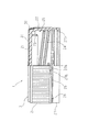
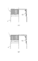
以下、本発明の広口容器用ネジキャップの実施形態について、図面に基づいて詳細に説明する。なお、図1は、本実施形態のネジキャップの構造を右半分を断面として側面視で示すものであり、また、図2(A),(B)は、図1に示したネジキャップの広口容器における(A)未開封の装着状態と(B)開封時の状態をそれぞれ示し、図3は、図1に示したネジキャップの一部の断面を拡大して示すものである。
【0018】
本実施形態のネジキャップ(スクリューキャップ)1は、同じ材質の合成樹脂材により一体成形された樹脂キャップ2と、その頂部外面を被覆する金属薄板製のシェル3とからなる複合材のキャップであって、図2(A),(B)に示すように、広口で再封鎖可能な金属缶(広口リシール缶)4のネジ付きの口頸部40に対して、ピルファープルーフ性を備えた状態で、螺合によって冠着されるものである。
【0019】
ネジキャップ1の樹脂キャップ2では、頂部21の周縁から下方に垂下してスカート部22が形成されており、スカート部22と所定の間隔を置いて同心的に、円筒状のインナープラグ23が頂部21の内面(下面)から垂設されていて、スカート部22の上端部内面とインナープラグ23の外面の間に、図3に示すように、缶4の口頸部40の上端カール部41が挿入されることとなる。
【0020】
樹脂キャップ2のスカート部22には、その内面側に、缶の口頸部40に形成されたネジ42と螺合するネジ24が形成され、その外面側に、ネジキャップ1を指で掴んで回す時の滑り止めとなるローレット(多数の細かい縦溝と縦リブ)25が形成されていて、スカート部22の下方には、不正使用を示す(開封されたかどうかを示す)ためのピルファープルーフ(タンパーエビデンス)機構が一体的に形成されている。
【0021】
ピルファープルーフ機構は、スカート部22の下端に、破断容易な弱化部となる連結部26を介して、缶の口頸部40の下部に係止されるバンド部27を形成したものであり、図3に示すように、缶の口頸部40の下部に上側が傾斜して下側が段部となった環状の突起43が形成されているのに対して、バンド部27の内面には、下側が傾斜して上側が段部となった環状の突起27bが形成されていて、ネジキャップ1を缶の口頸部40に螺着すると、バンド部27の突起27bが口頸部40の突起43を乗り越えて、両方の突起27b,43の段部同士が係合できるようになっている。
【0022】
また、スカート部22の下端とバンド部27の上端のそれぞれには、対向する凹部22aと凸部27aが形成されており、この凹部22aと凸部27aは、常態では噛み合うことなく、ネジキャップ1の螺着によりバンド部27の突起27bが口頸部40の突起43を乗り越える際に、その抵抗力により連結部26が縮むように弾性変形してスカート部22とバンド部27の間隔が狭まったときに、凹部22aと凸部27aが噛み合って、スカート部22とバンド部27がキャップの円周方向で連係するようになっている。
【0023】
このようなピルファープルーフ機構によれば、ネジキャップ1を装着する際には、バンド部27の突起27bが口頸部40の突起43を乗り越えるときに、凹部22aと凸部27aを介してスカート部22とバンド部27がキャップの円周方向で連係するため、キャップ1の回動が連結部26の切断力として働くことはなく、そのため、弱化部となる連結部26を切断され易いものにしても、ネジキャップ1の装着時に連結部26が切断されることはない。
【0024】
一方、ネジキャップ1を開封する際には、バンド部27が口頸部の突起43に係合している状態で、スカート部22が上方に移動することから、凹部22aと凸部27aは噛み合わず、スカート部22とバンド部27が凹部22aと凸部27aを介して連係することはないため、キャップ1の回動が連結部26の切断力として働き、弱化部となる連結部26を切断され易いものとしておくことで、その分だけネジキャップ1の開封時に弱い力で連結部26を切断することができるようになる。
【0025】
上記のようなピルファープルーフ機構が一体成形された樹脂キャップ2に対して、円形の頂板31の周縁から下方に短い円筒部32を垂下させた金属薄板製のシェル3が、樹脂キャップ2の頂部21の外面側を被覆するように一体的に設けられており、金属シェル3の内面と樹脂キャップ2の外面は一体的に接着され、金属シェル3の円筒部32の下部は、樹脂キャップ2のスカート部22の上端部分に埋設されている。
【0026】
なお、本実施形態では、樹脂キャップ2に埋設された金属シェル3の円筒部32の下端は、図3に示すように、ネジキャップ1を缶4の口頸部40に螺着した状態において、該口頸部40の上端位置(カール部41の上端)よりも下方にまで垂下されており、この円筒部32の下端は、外方に突出する鍔部33として、円筒部32の外径よりも外方向に0.2〜0.8mm突出するように曲げられている。(なお、この鍔部33は、円筒部32の内径よりも内方向に0.2〜0.8mm突出するように曲げても良い。)
【0027】
上記のような構造を備えた本実施形態のネジキャップ1について、更に具体例によって詳しく説明すると、樹脂キャップ2については、例えば、金属シェル3を金型内にセットし、合成樹脂としてポリプロピレンを樹脂温度230℃、射出圧60〜65kg/cm2 、成形サイクル28秒でインジェクション成形により金属シェル3の周囲に一体成形されるものである。なお、上記のような樹脂キャップ2の成形法については、インジェクション成形に限らず、コンプレッション成形によっても成形可能である。
【0028】
金型内にセットされる金属シェル3については、例えば、厚さ0.20mmの3004材アルミニウム合金板に対し、外面塗装として、ポリエステル系樹脂〔大日本インキ工業(P−926−2)〕を60mg/dm2 塗装して170℃×10分焼き付け、また、内面塗装として、ポリプロピレン(PP)分散エポキシ−フェノール〔大東ペイント(ダイトロン#5378PP−2)〕を60mg/dm2 塗装して190℃×10分焼き付けてから、所定の形状にプレス成形したものである。
【0029】
なお、樹脂キャップ2の材料となる合成樹脂については、容器の用途に応じてポリプロピレン(PP)よりも耐熱性の劣るポリエチレン(PE)を使用することも可能であり、また、金属シェル3の材料となる金属薄板についても、アルミニウム合金板に限らず、錫メッキ鋼板,亜鉛メッキ鋼板,ニッケルメッキ鋼板等の表面処理鋼板を使用することも可能である。
【0030】
金属シェル3の内面塗装については、エポキシ樹脂成分と、フェノール樹脂,尿素樹脂,メラミン樹脂及び熱硬化型アクリル樹脂からなる群より選ばれた少なくとも1種の熱硬化性樹脂との組み合わせからなる合成樹脂を主成分として、それに樹脂キャップ2の合成樹脂と同種の合成樹脂を分散させた塗料を使用することにより、金属シェル3の内面側と樹脂キャップ2との接着性を良くすることができる。
【0031】
すなわち、樹脂キャップ2の材料がポリプロピレンである場合には、主成分となる樹脂の中にポリプロピレン又はカルボキシル変性ポリプロピレンの粉末を分散させた塗料を使用するのが好ましく、また、樹脂キャップ2の材料がポリエチレンである場合には、主成分となる樹脂の中にポリエチレン又はカルボキシル変性ポリエチレンの粉末を分散させた塗料を塗布することが好ましい。
【0032】
以上に述べたような本実施形態の広口容器用ネジキャップ1によれば、スカート部22と弱化部26とバンド部27を合成樹脂材により一体成形していることで、開封時の滑り止めとなるローレット25をネジ24の外面側を含むスカート部22の全体に付与することができ、且つ、弱化部26を破断に大きな力を要しないものにすることができて、ネジキャップ1が大径であっても、弱化部26を破断しながらの開封の動作をやり易くすることができ、一方、ネジキャップ1の頂部外面を金属シェル3により被覆していることで、充分なガスバリヤー性(耐気体透過性)を確保することができる。
【0033】
そして、ネジキャップ1の頂部外面を被覆する金属シェル3と共に(樹脂成形用の金型内に金属シェル3を入れた状態で)、ネジキャップ1の各部分を同じ合成樹脂材により樹脂キャップ2として一体成形していることで、金属薄板と合成樹脂の複合材によるネジキャップ1を、通常の樹脂製キャップと同様に簡単に製造することができて、製造コストを安価に抑えることができる。
【0034】
なお、本実施形態では、樹脂キャップ2のスカート部の上端部分に埋設されている金属シェル3の円筒部32の下端を、キャップ1を広口リシール缶4の口頸部40に螺着させた状態において、該口頸部40の上端位置よりも下方にまで垂下させていることにより、ネジキャップ1においてガスバリヤー性が必要な部分を金属シェル3により略完全にカバーすることができて、ネジキャップ1のガスバリヤー性が一層向上されたものとなっている。
【0035】
また、本実施形態では、樹脂キャップ2に埋設されている金属シェル3の円筒部32の下端を、樹脂キャップ2の一部と充分に噛み合い、且つ、スカート部22の外面より突出しないように、該円筒部32の外径から外方向に0.2〜0.8mm突出する(或いは、内径から内方向に0.2〜0.8mm突出する)ような鍔部33として曲げていることにより、鍔部33と樹脂キャップ2の一部とが噛み合った状態となるので、ネジキャップ1が落下衝撃等を受けた場合でも、金属シェル3が樹脂キャップ2から抜け落ちて分離するようなことはない。
【0036】
さらに、本実施形態では、ネジキャップ1が螺着される容器本体は金属製の広口リシール缶4であるが、そのような金属缶の場合には、キャップ側のネジ24が樹脂であることにより、開封後にキャップの着脱を繰り返しても、金属缶の表面に被覆されている塗膜がキャップ側のネジ24との摩擦で剥がれるようなことはなく、缶のネジ部分が汚れるようなことはない。
【0037】
以上、本発明の広口容器用ネジキャップの一実施形態について説明したが、本発明は、上記の実施形態に示した具体例に限定されるものではなく、例えば、その用途については、上記の実施形態に示したような金属製の広口リシール缶に限らず、その他の広口容器のキャップとしても使用可能なものであり、また、その具体的な構造についても、例えば、装飾のために金属シェルの頂板に印刷加工や凹凸加工を施したり、密封のために樹脂キャップの頂部内面にインナープラグ以外にも環状のシール突起を設けたり、滑り止めとしてローレットに変えて幅の広い凹凸形状の滑り止めにしたり、或いは、ピルファープルーフ機構の具体的な構造を上記の実施形態に示したような構造以外のものとしたりする等、適宜設計変更可能なものであることは言うまでもない。
【0038】
【発明の効果】
以上説明したような本発明の広口容器用ネジキャップによれば、キャップの径が大きくても、ピルファープルーフ性を備えたキャップの開封を容易に行うことができ、また、キャップのガスバリヤー性を充分に確保することができて、容器内に密封された内容物の賞味期間を長くすることができ、しかも、簡単に製造することができて製造コストを安価に抑えることができると共に、容器本体が金属缶の場合には、開封後のキャップの着脱の繰り返しにより缶のネジ部分が傷付いて汚れるようなことを防止することができる。
【図面の簡単な説明】
【図1】本発明の広口容器用ネジキャップの一実施形態について、右半分を断面として示す部分断面側面図。
【図2】図1に示したネジキャップの広口リシール缶における(A)未開封の装着状態と(B)開封時の状態について、それぞれ右半分を断面として示す部分断面側面図。
【図3】図1に示したネジキャップの一部の断面を拡大して示す断面図。
【符号の説明】
1 ネジキャップ
2 樹脂キャップ(合成樹脂材)
3 金属シェル(金属薄板製のシェル)
4 広口リシール缶(広口容器)
22 (キャップの)スカート部
24 (キャップの)ネジ
26 (キャップの)弱化部
27 (キャップの)バンド部
31 (金属シェルの)頂板
32 (金属シェルの)円筒部
33 鍔(金属シェルの円筒部の下端)
40 (広口容器の)口頸部[0001]
BACKGROUND OF THE INVENTION
The present invention relates to a screw cap that is screwed onto a mouth and neck portion of a wide-mouthed container, and more particularly to a screw cap for a wide-mouthed container having a pilfer-proof property that is a cap made of a composite material of a synthetic resin and a metal thin plate.
[0002]
[Prior art]
In a glass bottle, a plastic container, a metal can, etc., a container having a wide opening (the inner diameter of the opening is 35 mm or more) having a large opening has been widely used as a food container. In a container, a screw-type metal cap or resin cap that can be resealed (resealed) is commonly used as a cap for sealing the opening.
[0003]
On the other hand, screw caps (screw caps) that can be repeatedly opened and closed even after opening, cap skirts as a pilfer proof (tamper evidence) mechanism to indicate whether or not they have been tampered with before purchase. Conventionally, a band portion that is locked to the mouth-neck portion of the container is formed below the portion via a weakened portion that is easily broken.
[0004]
[Problems to be solved by the invention]
By the way, if it is a metal cap for a screw cap for a wide mouth container with pilfer proof properties, the metal plate of the cap skirt is deformed to form a screw, so the cap is gripped and turned. Unevenness (knurling, etc.) on the outer surface of the cap that prevents slipping can only be applied near the upper end of the skirt where no screw is formed, and with a metal cap, if the diameter is large, it has a large force to break the weakened portion Therefore, the opening operation of removing the cap while breaking the weakened portion is difficult.
[0005]
Also, in the case of a metal cap, when the container body of the wide-mouthed container is a metal can with a screw (reseal can), by repeatedly removing and attaching the cap to open / close the container after opening, The coating film coated as a protective coating on the surface of the metal can is peeled off due to friction, and the metal surface of the can is exposed, so that the screw portion of the can becomes dirty and gives an unsanitary feeling.
[0006]
In contrast to such a metal cap, in the case of a resin cap, unevenness for preventing slipping can be imparted to the entire skirt portion including the outer surface side of the screw, and the weakening portion is broken so much. Even if the cap has a large diameter, the opening operation while breaking the weakened portion can be easily performed.
[0007]
In addition, in the case of a resin cap, when the container body is a metal can with a screw, even if the cap is repeatedly attached and detached after opening, the coating film that covers the surface of the metal can is caused by friction with the resin screw on the cap side. Since it is not peeled off, the screw part of the can is not soiled.
[0008]
However, resin caps are inferior in gas barrier properties (gas permeation resistance) compared to metal caps, especially when the area of the opening is large, such as a wide-mouthed container, due to the inferior gas barrier properties. There is a drawback in that the effect becomes significant and the shelf life of the contents sealed in the container is shortened.
[0009]
In this regard, Japanese Patent Application Laid-Open No. 6-122463 discloses a hermetically sealed cap formed such that the outer surface side of the top surface is a metal plate and the inner surface side is a synthetic resin in order to give the resin cap gas barrier properties. However, the sealing cap disclosed in the publication is a snap-in snap cap and is not a screw cap having a pilfer-proof property.
[0010]
In such a snap-in snap cap, the sealing performance is inferior when the engagement force between the cap and the container body is weak, and conversely, the unsealing property is inferior when the engagement force is increased, compared with a screw cap having a pilfer proof property. Since there is a problem and the cap itself is not provided with pilfer proof properties, it is necessary to seal the outside of the cap with shrink wrap as a means of preventing unauthorized use, and new shrink wrap processes and materials Therefore, the manufacturing cost increases.
[0011]
Further, in the sealing cap described in the above publication, in order to seal the container mouth with the cap, another hard synthetic resin different from the soft synthetic resin forming the top surface (top portion) and the side wall (skirt portion). A hard synthetic resin member is manufactured separately from the soft synthetic resin member by covering the side wall (skirt portion) from the outside downward from the outer peripheral edge of the top surface (top portion) by the member, and the soft synthetic resin member Since the process to fit in becomes necessary, manufacturing cost becomes high.
[0012]
An object of the present invention is to solve the above problems. Specifically, a screw cap for a wide-mouth container having a pill fur proof property is easy to open, has excellent gas barrier properties, and It is easy to manufacture, and even if the container body is a metal can, it is an object to prevent the screw part of the can from being damaged and soiled by repeated attachment and detachment of the cap after opening. Is.
[0013]
[Means for Solving the Problems]
In order to solve the above-described problems, the present invention is a screw cap that is screwed onto the mouth-neck portion of a wide-mouth container, and includes a skirt portion that hangs downward from the top peripheral edge and has a screw formed on the inner surface. A screw cap in which a band portion that is locked to the mouth and neck portion of the container is formed through a weakened portion that can be easily broken, with the top outer surface of the cap covered with a thin metal shell. Are formed integrally with the same synthetic resin material, and the metal shell that covers the top outer surface of the cap has a cylindrical portion that hangs downward from the peripheral edge of the circular top plate. Is embedded in synthetic resin at the upper end of the skirt, and the lower end of the cylindrical portion of the metal shell is lower than the upper end of the mouth and neck of the container with the cap screwed onto the mouth and neck of the container. until allowed to droop And wherein the Rukoto [0014]
According to the screw cap for a wide-mouth container having the above-described configuration, the skirt portion, weakened portion, and band portion of the cap are integrally formed of a synthetic resin material, so that unevenness that prevents slipping at the time of opening is formed on the outer surface of the screw. Since it can be applied to the entire skirt including the side and does not require a large force to break the weakened part, it is easy to perform the opening operation while breaking the weakened part even if the cap has a large diameter It can be.
[0015]
Moreover, the gas barrier property is required in the cap by suspending the lower end of the cylindrical portion of the metal shell embedded in the synthetic resin at the upper end portion of the skirt portion below the upper end position of the mouth and neck portion. The part can be almost completely covered with a short cylindrical metal shell, so that sufficient gas barrier properties are ensured. In addition, each part of the cap is integrally molded with the same synthetic resin material together with the metal shell. Therefore, a cap made of a composite material can be easily manufactured by a manufacturing method that is almost the same as that of a normal resin cap.
[0016]
In addition, when the container body to which the cap is screwed is a metal can with a screw (reseal can), if the screw cap having the above configuration is used, even if the cap is repeatedly attached and detached after opening, the cap side Since the screw is a resin, the coating on the surface of the metal can is not peeled off due to friction with the screw on the cap side, and the screw portion of the can is not soiled.
[0017]
DETAILED DESCRIPTION OF THE INVENTION
Hereinafter, embodiments of a screw cap for a wide-mouth container of the present invention will be described in detail based on the drawings. FIG. 1 shows the structure of the screw cap of this embodiment in a side view with the right half taken as a cross section. FIGS. 2A and 2B show the wide mouth of the screw cap shown in FIG. (A) The unopened mounting state and (B) the unsealed state of the container are shown, respectively, and FIG. 3 is an enlarged view of a part of the screw cap shown in FIG.
[0018]
A screw cap (screw cap) 1 according to the present embodiment is a composite cap composed of a
[0019]
In the
[0020]
The
[0021]
The pilfer proof mechanism is formed by forming a
[0022]
Moreover, the recessed
[0023]
According to such a pilfer proof mechanism, when the screw cap 1 is mounted, when the
[0024]
On the other hand, when the screw cap 1 is opened, the
[0025]
A
[0026]
In the present embodiment, the lower end of the
[0027]
The screw cap 1 of the present embodiment having the above-described structure will be described in more detail with a specific example. For the
[0028]
For the
[0029]
In addition, about the synthetic resin used as the material of the
[0030]
For the inner surface coating of the
[0031]
That is, when the material of the
[0032]
According to the wide-mouth container screw cap 1 of the present embodiment as described above, the
[0033]
Then, together with the
[0034]
In the present embodiment, the lower end of the
[0035]
In the present embodiment, the lower end of the
[0036]
Furthermore, in this embodiment, the container main body to which the screw cap 1 is screwed is the metal wide-mouthed reseal can 4. In such a metal can, the cap-
[0037]
As mentioned above, although one Embodiment of the screw cap for wide mouth containers of this invention was described, this invention is not limited to the specific example shown in said embodiment, For example, about the use, said implementation It can be used not only as a metal wide-mouthed reseal can as shown in the form, but also as a cap for other wide-mouthed containers. The top plate is printed or uneven, or the seal cap is provided with an annular seal protrusion on the inner surface of the top of the resin cap in addition to the inner plug. Or the specific structure of the pilfer proof mechanism can be changed as appropriate, such as a structure other than that shown in the above embodiment. It goes without saying.
[0038]
【The invention's effect】
According to the screw cap for a wide-mouth container of the present invention as described above, even when the cap diameter is large, it is possible to easily open the cap with pill fur proof property, and the gas barrier property of the cap. Can be secured sufficiently, the shelf life of the contents sealed in the container can be lengthened, and can be easily manufactured, and the manufacturing cost can be reduced at a low cost. In the case where the main body is a metal can, it is possible to prevent the screw portion of the can from being damaged due to repeated attachment and detachment of the cap after opening.
[Brief description of the drawings]
FIG. 1 is a partial cross-sectional side view showing a right half as a cross section of an embodiment of a screw cap for a wide-mouth container of the present invention.
2 is a partial cross-sectional side view showing the right half as a cross-section of the wide open reseal can of the screw cap shown in FIG.
3 is an enlarged cross-sectional view of a part of the screw cap shown in FIG. 1;
[Explanation of symbols]
1
3 Metal shell (shell made of thin metal sheet)
4 Wide mouth reseal can (wide mouth container)
22 (cap) skirt part 24 (cap) screw 26 (cap) weakening part 27 (cap) band part 31 (metal shell) top plate 32 (metal shell)
40 Mouth and neck (in wide-mouth container)
Claims (2)
Priority Applications (1)
| Application Number | Priority Date | Filing Date | Title |
|---|---|---|---|
| JP36869899A JP4297465B2 (en) | 1999-12-27 | 1999-12-27 | Screw cap for wide mouth container |
Applications Claiming Priority (1)
| Application Number | Priority Date | Filing Date | Title |
|---|---|---|---|
| JP36869899A JP4297465B2 (en) | 1999-12-27 | 1999-12-27 | Screw cap for wide mouth container |
Publications (3)
| Publication Number | Publication Date |
|---|---|
| JP2001180707A JP2001180707A (en) | 2001-07-03 |
| JP2001180707A5 JP2001180707A5 (en) | 2005-09-29 |
| JP4297465B2 true JP4297465B2 (en) | 2009-07-15 |
Family
ID=18492509
Family Applications (1)
| Application Number | Title | Priority Date | Filing Date |
|---|---|---|---|
| JP36869899A Expired - Fee Related JP4297465B2 (en) | 1999-12-27 | 1999-12-27 | Screw cap for wide mouth container |
Country Status (1)
| Country | Link |
|---|---|
| JP (1) | JP4297465B2 (en) |
Families Citing this family (3)
| Publication number | Priority date | Publication date | Assignee | Title |
|---|---|---|---|---|
| JP2006036255A (en) * | 2004-07-26 | 2006-02-09 | Alcoa Closure Systems Japan Ltd | Metal container, closure device and drink enclosed in container |
| JP2006052000A (en) * | 2004-08-16 | 2006-02-23 | Alcoa Closure Systems Japan Ltd | Metal container, closure device, and drink enclosed in container |
| JP4864507B2 (en) * | 2006-03-29 | 2012-02-01 | 東洋理工株式会社 | Watering equipment for breeding laboratory animals |
-
1999
- 1999-12-27 JP JP36869899A patent/JP4297465B2/en not_active Expired - Fee Related
Also Published As
| Publication number | Publication date |
|---|---|
| JP2001180707A (en) | 2001-07-03 |
Similar Documents
| Publication | Publication Date | Title |
|---|---|---|
| US4747500A (en) | Tamper indicating transparent closure | |
| US4813561A (en) | Composite retortable closure | |
| US4863061A (en) | Closure liner with pull tab | |
| US4852751A (en) | Tamper indicating container-closure package | |
| EP1773674B1 (en) | Method of sealing a container with a wadless closure | |
| JP3990807B2 (en) | Plastic cap | |
| GB2432153A (en) | Wadless closure | |
| JP2001139053A (en) | Structure of hermetical sealing liner for cap mounted on screwed can | |
| JP4297465B2 (en) | Screw cap for wide mouth container | |
| US4817807A (en) | Tamper-evident container | |
| JP4151815B2 (en) | Composite cap | |
| JP4121685B2 (en) | Cap with a sweepstakes mark | |
| JP2001199460A (en) | Cap for wide-mouthed container and manufacturing method therefor | |
| JP3611630B2 (en) | Closing device and synthetic resin cap | |
| JP3524975B2 (en) | Cap with clear opening function | |
| JPH0712295Y2 (en) | Barrier type cap | |
| JP4771034B2 (en) | Hinge cap with tamper evidence | |
| JPH0891402A (en) | Closure device | |
| US20230356897A1 (en) | Mold-material flip-top tamper evident closure | |
| JP3715359B2 (en) | Composite container lid with tamper evident characteristics | |
| JP3961630B2 (en) | Combination cap | |
| JP3586261B2 (en) | cap | |
| JP3529170B2 (en) | Synthetic resin cap with tamper-evident properties | |
| JP2004284607A (en) | Lid for metal container, and metal container with lid | |
| JP4355150B2 (en) | Plastic cap |
Legal Events
| Date | Code | Title | Description |
|---|---|---|---|
| A521 | Written amendment |
Free format text: JAPANESE INTERMEDIATE CODE: A523 Effective date: 20050509 |
|
| A621 | Written request for application examination |
Free format text: JAPANESE INTERMEDIATE CODE: A621 Effective date: 20050509 |
|
| A977 | Report on retrieval |
Free format text: JAPANESE INTERMEDIATE CODE: A971007 Effective date: 20080410 |
|
| A131 | Notification of reasons for refusal |
Free format text: JAPANESE INTERMEDIATE CODE: A131 Effective date: 20080507 |
|
| A521 | Written amendment |
Free format text: JAPANESE INTERMEDIATE CODE: A523 Effective date: 20080624 |
|
| TRDD | Decision of grant or rejection written | ||
| A01 | Written decision to grant a patent or to grant a registration (utility model) |
Free format text: JAPANESE INTERMEDIATE CODE: A01 Effective date: 20090413 |
|
| A01 | Written decision to grant a patent or to grant a registration (utility model) |
Free format text: JAPANESE INTERMEDIATE CODE: A01 |
|
| A61 | First payment of annual fees (during grant procedure) |
Free format text: JAPANESE INTERMEDIATE CODE: A61 Effective date: 20090413 |
|
| R150 | Certificate of patent or registration of utility model |
Free format text: JAPANESE INTERMEDIATE CODE: R150 |
|
| FPAY | Renewal fee payment (event date is renewal date of database) |
Free format text: PAYMENT UNTIL: 20120424 Year of fee payment: 3 |
|
| FPAY | Renewal fee payment (event date is renewal date of database) |
Free format text: PAYMENT UNTIL: 20130424 Year of fee payment: 4 |
|
| FPAY | Renewal fee payment (event date is renewal date of database) |
Free format text: PAYMENT UNTIL: 20130424 Year of fee payment: 4 |
|
| FPAY | Renewal fee payment (event date is renewal date of database) |
Free format text: PAYMENT UNTIL: 20130424 Year of fee payment: 4 |
|
| FPAY | Renewal fee payment (event date is renewal date of database) |
Free format text: PAYMENT UNTIL: 20140424 Year of fee payment: 5 |
|
| R250 | Receipt of annual fees |
Free format text: JAPANESE INTERMEDIATE CODE: R250 |
|
| LAPS | Cancellation because of no payment of annual fees |