JP4296876B2 - Air conditioner - Google Patents
Air conditioner Download PDFInfo
- Publication number
- JP4296876B2 JP4296876B2 JP2003294320A JP2003294320A JP4296876B2 JP 4296876 B2 JP4296876 B2 JP 4296876B2 JP 2003294320 A JP2003294320 A JP 2003294320A JP 2003294320 A JP2003294320 A JP 2003294320A JP 4296876 B2 JP4296876 B2 JP 4296876B2
- Authority
- JP
- Japan
- Prior art keywords
- air conditioner
- heating
- mold
- blower fan
- air
- Prior art date
- Legal status (The legal status is an assumption and is not a legal conclusion. Google has not performed a legal analysis and makes no representation as to the accuracy of the status listed.)
- Expired - Fee Related
Links
Images


Description
本発明は、カビの生長防止の機能を有する空調装置に関する。 The present invention relates to an air conditioner having a function of preventing mold growth.
空調装置内のカビの生長防止としては、エアコンのフィルタや熱交換器、送風ファンなどに銀や銅の化合物などの抗カビ処理をするのが一般的である。しかしながらこのような抗カビ処理をした空調装置であっても長期間使用してほこりが堆積した場合にはほこりの上にカビなどが繁殖してしまい下地の抗カビ処理の効果がみられないこともあった。そのため気相中のカビに直接作用するような抗カビ機構が開発されている。 In order to prevent mold growth in the air conditioner, it is common to perform anti-mold treatment of silver or copper compounds on air conditioner filters, heat exchangers, blower fans, and the like. However, even if such an anti-mold treatment air conditioner is used for a long period of time and dust accumulates, mold etc. will propagate on the dust and the effect of the anti-mold treatment of the groundwork is not seen There was also. Therefore, an antifungal mechanism that directly acts on mold in the gas phase has been developed.
人体に有害なオゾン濃度を下げながら負イオンを発生させる微生物繁殖防止機構を冷凍・空調装置に組み込んでいる。この場合、空気中の気体をイオン化する電離室とイオン化された気体に含まれるオゾンを除去するオゾン分解室ともつような微生物繁殖防止機構冷却ユニットの送風機の吹き出し口に配置している(例えば特許文献1参照)。 The refrigeration and air-conditioning system incorporates a microbial growth prevention mechanism that generates negative ions while lowering the ozone concentration harmful to the human body. In this case, it is arranged in the blower outlet of the cooling unit of the microorganism propagation prevention mechanism cooling unit having an ionization chamber for ionizing gas in the air and an ozonolysis chamber for removing ozone contained in the ionized gas (for example, a patent) Reference 1).
また、一定時間冷房運転を実施したのちに暖房運転を実施しその際にショートサーキット運転をして吹き出し気流を吸いこませることで空気調和機本体を乾燥させている(例えば特許文献2)。さらに空調装置にショートサーキット流路を設け、必要に応じて高温空気をショートサーキットさせて空調装置内を殺菌するものである(例えば特許文献3)。
しかしながら、このようなオゾンを発生させるような微生物繁殖防止機構は装置が複雑であり一定の大きさを必要とするため既存の空調装置に組み込むことは不可能であるという課題を有していた。また、気相で抗カビ効果を有するものはホコリ上に堆積したカビに有効であるが抗カビ成分を多孔質媒体に坦持させる必要があるため抗カビ剤の小型化や長寿命化が困難であった。また、空調装置の乾燥運転実施の場合、送風のみでは空調装置内を湿度低下させることは困難である。そのため空調装置内は高温高湿雰囲気が保たれてしまい防カビ効果がほとんど見られない。空調装置の乾燥運転の際に暖房運転を実施してもその頻度が少ない場合、防カビの効果が少なくすぐにカビの生長が始まってしまうことがあった。また夏場の冷房運転時は室外雰囲気温度が高いため暖房運転をおこなうと圧縮機が過負荷運転となり圧縮機の長期信頼性を損なうおそれがあった。なお空調装置内を殺菌しようとすれば空気装置本体を80℃以上の高温に保持せねばならず、空調装置内の樹脂部品を高温に耐える材料に変更する必要があった。 However, such a mechanism for preventing the propagation of microorganisms that generates ozone has a problem that the apparatus is complicated and requires a certain size, so that it cannot be incorporated into an existing air conditioner. In addition, those that have an antifungal effect in the gas phase are effective against mold deposited on dust, but it is necessary to support the antifungal component in a porous medium, making it difficult to reduce the size and extend the life of antifungal agents. Met. Further, in the case of carrying out the drying operation of the air conditioner, it is difficult to reduce the humidity inside the air conditioner only by blowing air. For this reason, a high-temperature and high-humidity atmosphere is maintained in the air conditioner, and an antifungal effect is hardly seen. Even if the heating operation is carried out during the drying operation of the air conditioner, if the frequency is low, the effect of mold prevention is small and mold growth may start immediately. Also, during the cooling operation in summer, the outdoor ambient temperature is high, so if the heating operation is performed, the compressor may be overloaded and the long-term reliability of the compressor may be impaired. In order to sterilize the inside of the air conditioner, the air device main body had to be kept at a high temperature of 80 ° C. or higher, and it was necessary to change the resin parts in the air conditioner to materials that can withstand high temperatures.
本願発明は、カビ生長を効果的に抑制する空調装置を提供することを目的とする。 An object of the present invention is to provide an air conditioner that effectively suppresses mold growth.
請求項1記載の本発明の空調装置は、空調装置内の送風ファン近傍の温度を検知する温度検知手段と、前記送風ファン内部に設置され前記送風ファンおよび装置内壁を加熱する加熱手段と、前記加熱手段の加熱制御からの経過時間をカウントするタイマー手段とを備え、前記タイマー手段により所定の時間に所定の時間間隔で前記加熱手段により加熱制御
を行うことを特徴とする。
The air conditioner of the present invention according to
請求項2記載の本発明の空調装置は、前記加熱手段で加熱制御する際に空調機吹出しルーバを閉じるように変えるルーバ駆動手段とを備えたことを特徴とする。 According to a second aspect of the present invention, there is provided an air conditioner according to the present invention, further comprising: a louver driving unit that changes an air conditioner blowout louver when the heating unit performs heating control.
請求項3記載の本発明の空調装置は、空調装置の吸いこみ部および吹出し部に開閉可能な窓を設け、前記加熱手段で加熱制御する際にこの開閉可能な窓を閉鎖するように変える窓閉鎖手段とを備えたことを特徴とする。 According to a third aspect of the present invention, there is provided an air conditioner according to the present invention, wherein a window that can be opened and closed is provided in a suction part and a blow-out part of the air conditioner, and the window that can be opened and closed when the heating means controls the heating. And a closing means.
請求項4記載の本発明の空調装置は、前記加熱手段で加熱制御後に空調装置内空気を外へ排出する排気手段を備えたことを特徴とする。 According to a fourth aspect of the present invention, there is provided an air conditioner according to the present invention, further comprising an exhaust means for discharging the air in the air conditioner to the outside after heating control by the heating means.
請求項5記載の本発明の空調装置は、前記加熱手段が輻射光発生手段であることを特徴とする。 The air conditioner according to a fifth aspect of the present invention is characterized in that the heating means is a radiant light generating means.
請求項6記載の本発明の空調装置は、前記加熱手段が少なくとも40℃で10分間の加熱をすることを特徴とする。 The air conditioner according to a sixth aspect of the present invention is characterized in that the heating means heats at least 40 ° C. for 10 minutes .
上記実施例から明らかなように、所定の時間に所定の時間間隔で送風ファンおよび装置内壁に付着したカビの胞子や菌糸に繰り返しわずかな熱ダメージを与え生長を効果的に抑制することができるようになった。その結果送風ファンやその近傍にカビのコロニーが形成されることがないので、カビの繁殖による臭いを低減した空調装置を提供できる。 As is clear from the above-described embodiment, the growth fan can be effectively suppressed by repeatedly giving slight thermal damage to the blower fan and the mold spores and mycelium adhering to the inner wall of the apparatus at a predetermined time interval at a predetermined time. Became. As a result, mold colonies are not formed in the blower fan or in the vicinity thereof, so that an air conditioner with reduced odor due to mold growth can be provided.
また、加熱の際に空調装置吹出しルーバを閉じるように変えたので、送風ファン近傍を短時間で所定の温度に到達させることができるようになった。その結果、より効果的に加熱によりカビの繁殖を抑制することができ、加熱時に温風が空調装置から室内へ放出されないので使用者の不快感を低減できる。 Moreover, since it changed so that an air-conditioner blowing louver might be closed in the case of a heating, it came to be able to reach predetermined temperature in the ventilation fan vicinity in a short time. As a result, the propagation of mold can be suppressed more effectively by heating, and since warm air is not released into the room from the air conditioner during heating, user discomfort can be reduced.
また、吸いこみ部および吹出し部に開閉可能な窓を設けたので送風ファンを加熱する際にこの窓を閉鎖することができるようになり、送風ファン近傍を短時間で所定の温度に到達させることができるようになった。その結果、より効果的に加熱でカビの繁殖を抑制することができ、防カビ制御運転の消費電力を減らすことができる。 In addition, since a window that can be opened and closed is provided in the suction part and the blow-out part, the window can be closed when the blower fan is heated, and the vicinity of the blower fan can reach a predetermined temperature in a short time. Can now. As a result, the growth of mold can be suppressed more effectively by heating, and the power consumption of the mold prevention control operation can be reduced.
また、加熱後に空調装置内空気を外へ排出する排出手段を備えているので防カビ運転の送風ファン近傍加熱後に空調装置から暖かい空気が放出されないので防カビ運転時の不快感を軽減することができる。 In addition, because it is equipped with a discharge means that discharges air inside the air conditioner after heating, warm air is not released from the air conditioner after heating in the vicinity of the blower fan during anti-mold operation, so that discomfort during the anti-mold operation can be reduced. it can.
また、加熱手段が送風ファン内部に設置されているので、効率的に送風ファン上のカビの生長を抑制することができる。 Moreover, since the heating means is installed inside the blower fan, the growth of mold on the blower fan can be efficiently suppressed.
また、熱手段が輻射光発生手段なので効率的に送風ファンを加熱することができるため送風ファン上のカビの生長を抑制することができる。 In addition, since the heat means is the radiant light generating means, the blower fan can be efficiently heated, so that the growth of mold on the blower fan can be suppressed.
また、加熱手段が送風ファンよりも低い位置にあるので加熱された空気が対流により送風ファン近傍に運ばれる。そのため送風ファン近傍を効率的に加熱することができる。 Further, since the heating means is located at a position lower than the blower fan, the heated air is carried near the blower fan by convection. Therefore, the vicinity of the blower fan can be efficiently heated.
なお、実施例では壁掛け型セパレートタイプおよび天井ビルトインタイプの空調装置について詳細に述べたが本発明はそれに限定されるわけではなく、一体型ウインドウエアコン、カーエアコンなど冷房で使用し空調装置内部の湿度が上昇するような空調装置全般に適用可能である。また送風ファンについてもクロスフローファンだけの説明をしたが、シロッコファン、プロペラファン、ターボファンなど公知のファンを用いることができる。 In the embodiment, the wall-mounted separate type and ceiling built-in type air conditioners have been described in detail. However, the present invention is not limited to this, and the humidity inside the air conditioner is used for cooling such as an integrated window air conditioner and a car air conditioner. It can be applied to any air conditioner that raises the Although only the cross flow fan has been described for the blower fan, a known fan such as a sirocco fan, a propeller fan, or a turbo fan can be used.
図1は本発明によるカビ生長を抑制するための空調装置の一実施例の室内機断面図である。以下図1を参照しながら本発明を説明する。室内機を通る空気の流れは、送風ファン1により起こされ、室内機前方または上方の吸入グリル2から入り、熱交換器3、送風ファン1、吹き出しルーバ4を通って室内機外へ出て行く。
FIG. 1 is a cross-sectional view of an indoor unit of an embodiment of an air conditioner for suppressing mold growth according to the present invention. The present invention will be described below with reference to FIG. The air flow through the indoor unit is caused by the
空調装置の室内機内は熱交換器3部分で結露するため、冷房または除湿運転期間中の室内機内は湿度が高くカビの生長が問題になる。カビの胞子は通常100μm以下で空気中に浮遊している。空調装置の室内機に空気と共に吸入されたカビ胞子は室内機内部に静電気またはオイルミスト等の汚れと共に付着する。室内機内の冷房または除湿期間中の相対湿度は運転中でほぼ100%、停止中でも90%以上を長時間保っている。カビの生長速度は温度や湿度により大きく変化する。一般に温度としては20℃〜30℃、湿度は70%以上で高いほうがカビの生長速度は速い。そのため室内機内ではカビの胞子の発芽、菌糸の生長、胞子の再生産が起こり室内機内がカビ汚染される。カビ汚染の最もひどい部分は送風ファン1の湿度の高くなりやすい部分である。送風ファン1はクロスフローファンを使用しており送風ファン1上でカビが生長するとそのブレード間で生長を重ねついにはファンのブレード間を塞ぎ、空調装置から風がでないようになってしまうこともある。空調装置内で生長しやすいカビは通常の室内に広く存在する好湿性のカビ、たとえばCladosporiumやAltanaria、Aspergillusなどである。本発明は、これらの空調装置内で生長しやすいカビに対して有効である。
Since the inside of the indoor unit of the air conditioner is condensed at the
図1において温度センサー5は送風ファン1の近傍の空調機器壁表面に設置されている。送風ファンは運転中常にブレードが風と衝突しているため、ブレード端面にカビ胞子が付着しカビコロニーを形成しやすい。本発明の温度センサー5はこのカビ胞子が付着しやすい送風ファン周辺の温度をコントロールしてカビ生長を抑制するのに用いる。温度センサー5は室温から50℃程度までの温度を検出できるものであればサーモスタットや温度ヒューズなどどのようなものでも構わない。なお、温度センサーは1箇所でも構わないが温度分布が存在する場合も考慮して送風ファン近傍で2箇所以上設置しても構わない。 この温度センサー5は所定の温度に所定時間保つように加熱手段6を制御するのに用いられる。カビの生長を抑制するためには最低でも40℃で10分間の加熱が必要になる。温度の上限は樹脂の劣化しない温度であり、ポリスチレン樹脂を空調装置の筐体に用いた場合では80℃以下に保つのが好ましい。
In FIG. 1, the
加熱手段6は送風ファン1を加熱できるのであれば、どのような位置にあっても構わないが加熱空気は比重が軽くなって上方へ移動するため、送風ファンよりも低い位置に設置するのが好ましい。図1の実施例では吹出し出口の近傍に設置してあるがこの位置にこだわるものではない。加熱手段6は送風ファン1および近傍の空気を加熱する必要がある。そのため送風ファンがクロスフローファンのように細長い場合は加熱手段もそれに合わせて長くするのが好ましい。本実施例ではクオーツヒータを用いているが加熱手段は特に限定しない。ニクロム線、クオーツヒータ等公知のものを用いることができる。カーボンランプヒータのように輻射により送風ファンの温度を上昇させるものはすばやく温度上昇させることができ防カビ運転を短時間で済ませることができるために好ましい。また、カーボンランプヒータのような輻射を用いる場合、クロスフローファンや装置内壁は黒色にした方が、効率的に熱を吸収することができるために好ましい。
The heating means 6 may be in any position as long as it can heat the
加熱手段6により送風ファン1を加熱するタイミングと加熱保持時間はタイマー7によってコントロールされる。発明者らは空調機内に発生しやすいカビについて毎日1回40℃以上で加熱することによりカビの生長を抑制することができるということを見出した。そのためタイマー7は1日1回10分間加熱手段が通電されるようにセットされている。1日のうち何時に防カビ制御がスタートするかは使用者により決定される。在室者が少ない時に防カビ制御がスタートするように設定することで空調機から漏洩してくる加熱空気による不快感を極力減らすのが望ましい。
The
また、送風ファン1を停止した状態で加熱しても回転させた状態で加熱してもどちらでも構わない。回転させる場合は暖かい風が室内に拡散しないように吹出しルーバ4を吸いこみ方向に少しだけ開けて空調装置内を通る風がショートカットして循環するようにしても構わない。しかしより効率的に送風ファン1を加熱するために送風ファンを加熱する際に吹出しルーバ4を閉じるようなルーバ駆動手段(図示せず)を備えている。
Moreover, it does not matter whether the
次に本発明の別の実施例を図2に示す。これは天井ビルトインタイプの空調装置の室内側前面パネル上に本発明の防カビ手段を設置した一実施例の断面図である。図2を参照しながら本発明を説明をする。図1の壁掛け型室内機と同様に天井ビルトインタイプの室内機を通る空気の流れは、送風ファン1により起こされ、吸入グリル2から入り、熱交換器3、送風ファン1、吹き出しルーバ4を通って室内機外へ出て行く。図2では室内機の室内側パネルのさらに室内側に防カビ手段8を設置している。防カビ手段8は図2に示すように下方に開閉可能な窓9を設けている。この窓はすべての窓が連動して開閉できるようにモータと開閉機構(図示せず)を備えている。また、加熱イベントが起こった時点で閉じ、加熱している間は閉じつづける制御になっている。この窓9を防カビ運転中に閉じることで室内機内は効率よく加熱される。この防カビ手段8内には加熱手段6とタイマー7が設置されていて所定の時間に所定の間隔だけ加熱できるように加熱手段6とタイマー7が制御手段(図示せず)を通して接続されている。さらに温度センサー5が送風ファン1の近傍の空調機器壁表面に設置され、加熱手段6と制御手段を通して接続されており、加熱時に送風ファン近傍の温度が40℃から80℃に保っている。
Next, another embodiment of the present invention is shown in FIG. This is a sectional view of an embodiment in which the anti-mold means of the present invention is installed on the indoor front panel of a ceiling built-in type air conditioner. The present invention will be described with reference to FIG. As with the wall-mounted indoor unit of FIG. 1, the air flow through the ceiling built-in type indoor unit is caused by the
なお防カビ手段8は天井ビルトイン型室内機とは公知の方法で固定することができる。たとえば前面グリルと天井の隙間に防カビ手段8の天板を差し込むことで容易に固定および脱着することができる。またこの防カビ手段8の中に電気集塵ユニットを設置して集塵性能を持たせることもできる。電気集塵ユニットを付加することで空調装置の中にカビの胞子が侵入する前に集塵するとともに集塵できなかったカビについては防カビ手段によりカビの生長を押さえることができる。このようにして従来にはない高効率にカビを制御した空調装置を提供することができる。 The mold prevention means 8 can be fixed to the ceiling built-in indoor unit by a known method. For example, it can be easily fixed and detached by inserting the top plate of the anti-mold means 8 into the gap between the front grille and the ceiling. In addition, an electric dust collection unit can be installed in the mold prevention means 8 to provide dust collection performance. By adding an electric dust collecting unit, dust is collected before mold spores enter the air conditioner, and mold that cannot be collected can be suppressed by mold prevention means. In this way, it is possible to provide an air conditioner in which mold is controlled with high efficiency that has not been conventionally achieved.
また図2に示した空調装置には排気手段10が接続されており、空調装置内の空気を室外へ送ることができる。排気手段10は排気口と風路切替え器(図示せず)により構成されている。また排気手段は家全体の換気装置にダクトを通して接続されていても構わない。空調装置内を所定の時間加熱したのち風路切替え器により排気口を開け熱風を排気手段より外部へ放出する。その結果防カビ制御運転直後の熱い空気を室内に送らなくて済むため居住者の快適性が向上する。
2 is connected to an
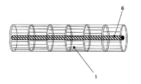
次に図3に本発明の加熱手段6の空調装置内での設置の一例を示す。図3は送風ファン1の斜視図である。ここでは空調装置でよく用いられる、クロスフローファンを示している。加熱手段6は送風ファン1の軸心部分に設置されている。ファンの軸心部分に設置することで送風ファンを容易に40℃以上に加熱することができエネルギー消費を少なくすることができるので最適である。
Next, FIG. 3 shows an example of installation of the heating means 6 of the present invention in the air conditioner. FIG. 3 is a perspective view of the
図4は図2に示した空調装置の防カビ運転についての制御フローチャートである。本防カビ運転はカビの発生が予想される時期、すなわち冷房運転を使用する時期に通常使用する。冷房運転時のエアコン室内機内は、空気中の水分が結露するため多湿状態となっておりカビの生長に適した条件となっている。また除湿運転時は室内空気を露点以下に下げて空気中から水分を除去することで除湿を実現している。したがって第4図に示したフローチャートは除湿運転時にも同様に使用することができる。 FIG. 4 is a control flowchart for the anti-mold operation of the air conditioner shown in FIG. This mold prevention operation is usually used at the time when mold is expected to be generated, that is, when the cooling operation is used. The air conditioner indoor unit during the cooling operation is in a humid state due to condensation of moisture in the air, which is a condition suitable for mold growth. During dehumidifying operation, dehumidification is achieved by lowering the room air below the dew point and removing moisture from the air. Therefore, the flowchart shown in FIG. 4 can be used in the same manner during the dehumidifying operation.
本防カビ運転は、通常運転時にはタイマーを動作させているのみで加熱手段への通電は行わない。1日1回タイマで設定した時間になると送風ファンを停止するとともに防カビ手段の前面窓を閉鎖し、続いて加熱手段へ通電を開始する。タイマの設定は使用者が手動行っても構わないし、ネットワークを介して設備会社等エアコン保守担当者が遠隔操作しても構わないが1日に1回以上の加熱が必要である。1日に1回の加熱ができない場合はカビの生長を停止させることができず、本発明の効果を実現できない。 In the anti-mold operation, only the timer is operated during normal operation, and the heating means is not energized. When the time set by the timer once a day is reached, the blower fan is stopped and the front window of the mold prevention means is closed, and then the heating means is energized. The timer may be set manually by the user, or may be remotely operated by a person in charge of air conditioner maintenance such as an equipment company via a network, but heating is required once or more per day. If heating once a day is not possible, mold growth cannot be stopped and the effects of the present invention cannot be realized.
次に送風ファン近傍の温度センサからの温度情報をもとに設定温度の40℃になるように加熱手段へ通電する電流をコントロールする。40℃まで到達するのに要する時間は特に指定しないが冷房時に運転を停止することからできる限り短時間で40℃に到達させるべきである。送風ファン近傍が40℃に達した瞬間からタイマにより10分間計測し、送風ファン近傍のカビの生長を抑制する。そして次のステップで加熱を停止し風路を排気に切替えて送風ファンを運転して40℃の空気を室外へ排出する。2分後にファンを停止し排気風路を閉じて冷房運転を開始し防カビ手段の前面窓を開放する。 Next, based on temperature information from a temperature sensor in the vicinity of the blower fan, the current supplied to the heating means is controlled so that the set temperature is 40 ° C. The time required to reach 40 ° C. is not particularly specified, but the operation should be stopped at the time of cooling. A timer is used for 10 minutes from the moment when the vicinity of the blower fan reaches 40 ° C. to suppress the growth of mold near the blower fan. Then, in the next step, heating is stopped, the air passage is switched to exhaust, the blower fan is operated, and 40 ° C. air is discharged to the outside. After 2 minutes, the fan is stopped, the exhaust air passage is closed, the cooling operation is started, and the front window of the mold prevention means is opened.
1 送風ファン
2 吸入グリル
3 熱交換器
4 吹出しルーバ
5 温度センサ
6 加熱手段
7 タイマー
8 防カビ手段
9 開閉可能な窓
10 排気手段
DESCRIPTION OF
Claims (6)
Priority Applications (1)
| Application Number | Priority Date | Filing Date | Title |
|---|---|---|---|
| JP2003294320A JP4296876B2 (en) | 2003-08-18 | 2003-08-18 | Air conditioner |
Applications Claiming Priority (1)
| Application Number | Priority Date | Filing Date | Title |
|---|---|---|---|
| JP2003294320A JP4296876B2 (en) | 2003-08-18 | 2003-08-18 | Air conditioner |
Publications (2)
| Publication Number | Publication Date |
|---|---|
| JP2005061741A JP2005061741A (en) | 2005-03-10 |
| JP4296876B2 true JP4296876B2 (en) | 2009-07-15 |
Family
ID=34370921
Family Applications (1)
| Application Number | Title | Priority Date | Filing Date |
|---|---|---|---|
| JP2003294320A Expired - Fee Related JP4296876B2 (en) | 2003-08-18 | 2003-08-18 | Air conditioner |
Country Status (1)
| Country | Link |
|---|---|
| JP (1) | JP4296876B2 (en) |
Cited By (1)
| Publication number | Priority date | Publication date | Assignee | Title |
|---|---|---|---|---|
| CN111536670A (en) * | 2020-05-13 | 2020-08-14 | 广东美的制冷设备有限公司 | Air conditioner high-temperature sterilization control method, air conditioning equipment and readable storage medium |
Families Citing this family (4)
| Publication number | Priority date | Publication date | Assignee | Title |
|---|---|---|---|---|
| JP4807149B2 (en) * | 2006-06-02 | 2011-11-02 | パナソニック株式会社 | Air conditioner |
| JP5386849B2 (en) * | 2008-04-15 | 2014-01-15 | パナソニック株式会社 | Heat exchange device and heating element storage device using the same |
| JP5326666B2 (en) * | 2009-03-04 | 2013-10-30 | 三菱電機株式会社 | Air conditioner |
| CN113790509B (en) * | 2021-10-19 | 2022-07-19 | 宁波奥克斯电气股份有限公司 | Drying and mildew-proof control method for evaporator |
-
2003
- 2003-08-18 JP JP2003294320A patent/JP4296876B2/en not_active Expired - Fee Related
Cited By (2)
| Publication number | Priority date | Publication date | Assignee | Title |
|---|---|---|---|---|
| CN111536670A (en) * | 2020-05-13 | 2020-08-14 | 广东美的制冷设备有限公司 | Air conditioner high-temperature sterilization control method, air conditioning equipment and readable storage medium |
| CN111536670B (en) * | 2020-05-13 | 2021-08-31 | 广东美的制冷设备有限公司 | Air conditioner high-temperature sterilization control method, air conditioning equipment and readable storage medium |
Also Published As
| Publication number | Publication date |
|---|---|
| JP2005061741A (en) | 2005-03-10 |
Similar Documents
| Publication | Publication Date | Title |
|---|---|---|
| JP4581024B1 (en) | Air conditioner | |
| JPH06272888A (en) | Air conditioner | |
| JP5542046B2 (en) | Heat exchange ventilator | |
| JP4722210B2 (en) | Air conditioner | |
| JP6167297B2 (en) | Ventilation equipment | |
| JP4296876B2 (en) | Air conditioner | |
| JP2004293893A (en) | Air conditioner | |
| JPH11201511A (en) | Air cleaning system | |
| KR20120057919A (en) | Self-Preservation Driving Ventilator | |
| KR101790690B1 (en) | Ventilator having function of dew condensation prevention and the controlling method the same | |
| KR101526136B1 (en) | Energy regeneration type reversible fan ventilator and ventilation system and comprising the same | |
| KR20110135325A (en) | Door handle ventilation for natural heat exchange without power | |
| JP2002061916A (en) | Air conditioner | |
| JP3723167B2 (en) | Indoor unit for air conditioning and air conditioner equipped with the same | |
| KR102210161B1 (en) | Hybrid air purification system | |
| KR100698516B1 (en) | Heat Exchanging Ventilation System Built in Window | |
| KR20170079558A (en) | A ventilating fan | |
| JP2017009243A (en) | Odor adhesion inhibition system | |
| JP4083496B2 (en) | Air conditioner indoor unit | |
| JP2012097999A (en) | Air conditioner | |
| JP4381048B2 (en) | Air conditioner | |
| JP4369220B2 (en) | Air conditioner indoor unit | |
| JP2008020127A (en) | Radiation cooling and heating device | |
| JP2008170054A (en) | Ventilation system | |
| JP4083495B2 (en) | Air conditioner indoor unit |
Legal Events
| Date | Code | Title | Description |
|---|---|---|---|
| A621 | Written request for application examination |
Free format text: JAPANESE INTERMEDIATE CODE: A621 Effective date: 20060719 |
|
| RD01 | Notification of change of attorney |
Free format text: JAPANESE INTERMEDIATE CODE: A7421 Effective date: 20060821 |
|
| A977 | Report on retrieval |
Free format text: JAPANESE INTERMEDIATE CODE: A971007 Effective date: 20081225 |
|
| A131 | Notification of reasons for refusal |
Free format text: JAPANESE INTERMEDIATE CODE: A131 Effective date: 20090113 |
|
| A521 | Request for written amendment filed |
Free format text: JAPANESE INTERMEDIATE CODE: A523 Effective date: 20090224 |
|
| TRDD | Decision of grant or rejection written | ||
| A01 | Written decision to grant a patent or to grant a registration (utility model) |
Free format text: JAPANESE INTERMEDIATE CODE: A01 Effective date: 20090324 |
|
| A01 | Written decision to grant a patent or to grant a registration (utility model) |
Free format text: JAPANESE INTERMEDIATE CODE: A01 |
|
| A61 | First payment of annual fees (during grant procedure) |
Free format text: JAPANESE INTERMEDIATE CODE: A61 Effective date: 20090406 |
|
| FPAY | Renewal fee payment (event date is renewal date of database) |
Free format text: PAYMENT UNTIL: 20120424 Year of fee payment: 3 |
|
| LAPS | Cancellation because of no payment of annual fees |