JP4294792B2 - Wheelchair fixing device - Google Patents
Wheelchair fixing device Download PDFInfo
- Publication number
- JP4294792B2 JP4294792B2 JP15011799A JP15011799A JP4294792B2 JP 4294792 B2 JP4294792 B2 JP 4294792B2 JP 15011799 A JP15011799 A JP 15011799A JP 15011799 A JP15011799 A JP 15011799A JP 4294792 B2 JP4294792 B2 JP 4294792B2
- Authority
- JP
- Japan
- Prior art keywords
- wire
- drum
- wheelchair
- winding
- hook
- Prior art date
- Legal status (The legal status is an assumption and is not a legal conclusion. Google has not performed a legal analysis and makes no representation as to the accuracy of the status listed.)
- Expired - Fee Related
Links
- 238000004804 winding Methods 0.000 claims description 66
- 230000007246 mechanism Effects 0.000 claims description 54
- 239000003638 chemical reducing agent Substances 0.000 claims description 15
- 230000009467 reduction Effects 0.000 claims description 8
- 230000000452 restraining effect Effects 0.000 description 5
- 230000008901 benefit Effects 0.000 description 2
- 230000013011 mating Effects 0.000 description 2
- 230000009471 action Effects 0.000 description 1
- 230000008859 change Effects 0.000 description 1
- 230000000694 effects Effects 0.000 description 1
- 239000000463 material Substances 0.000 description 1
- 238000000034 method Methods 0.000 description 1
- 230000007480 spreading Effects 0.000 description 1
- 230000001360 synchronised effect Effects 0.000 description 1
- 229920003002 synthetic resin Polymers 0.000 description 1
- 239000000057 synthetic resin Substances 0.000 description 1
Images

Landscapes
- Transmission Devices (AREA)
- Storing, Repeated Paying-Out, And Re-Storing Of Elongated Articles (AREA)
Description
【0001】
【発明の属する技術分野】
本発明は車椅子固定装置に関する。さらに詳しくは、自動車の後部貨物室などに積載した展開状態の車椅子、とくに人が乗っている状態の車椅子を、ワイヤを利用して固定するための装置に関する。
【0002】
【従来の技術】
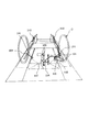
この種の固定装置は、特開平9−131376号公報に開示されている。このものは図8に示すように、左右一対のロープ101、102と、それらのロープの前部および後部に連結した前フック103および後フック104と、前フックおよび後フックをそれぞれ車椅子Cの横桟(フレーム)の外側および内側から引っかけられるように前記ロープを案内する一連の滑車ないしガイド群105、106と、左右のロープの中間部にそれぞれ連結された引っ張りロープ107、108と、それらの引っ張りロープをそれぞれ一緒に引き込むためのモータ駆動の送り装置109とを備えている。
【0003】
この固定装置は各フック103、104を車椅子Cのフレームの所定位置に引っ掛けて、左右の引っ張りロープ107、108を送り装置109で引き込むと、各フック103、104が外向きまたは内向きで、それぞれ下側に引っ張られる。そのため、車椅子Cを床面にしっかりと固定することができる。そして引っ張りロープ107、108を緩めると、フック103、104を外すことができる。
【0004】
この固定装置は、前後のフック103、104を1本のロープ101または102で釣瓶状に配索し、1個の駆動部で同時に引き込むように構成しているため、駆動部が1個所で済む利点がある。しかし図9のように車椅子Cを前後に傾ける外力が加わる場合など、前後のロープに「伸び・縮み」の相反する荷重が加わったときには、ロープが移動する可能性があり、充分な固定力を確保することができない。
【0005】
他方、特開平11−47193号公報には、図10に示すように前後左右のワイヤ111をそれぞれ独立した巻き取り機構112で巻き取るようにした車椅子固定装置が開示されている。それらの巻き取り機構112は、渦巻きバネの付勢力でワイヤ111を巻き取るようにしているので、手を離せば自動的にロープが巻き取られる利点がある半面、バネの付勢力だけでは充分な拘束力を与えることができない。そのため、各巻き取り機構のドラムをワイヤの巻き取り方向にいくらか回転させてワイヤに張力を加えながらロックするためのロック機構113を別個に設けている。
【0006】
このものは各ワイヤを個別にロックするので、車椅子を前後に傾ける外力に対しても拘束力を発揮する。しかし各ワイヤの拘束力は最初のワイヤの巻き取り量などによって異なり、各ワイヤの張力のバランスが取りにくい。とくに最初のワイヤの巻き取りが不充分な場合は、ロックをしても充分な拘束力が得られず、そのためロックする前にワイヤの張力を確認する必要があり、取り扱いが不便である。
【0007】
【発明が解決しようとする課題】
本発明は、車椅子の前後の傾動に対しても充分な拘束力を発揮することができ、しかも拘束・解除の取り扱いが簡単なワイヤ式の車椅子固定装置を提供することを技術課題としている。
【0008】
【課題を解決するための手段】
本発明の車椅子固定装置は、先端に車椅子の前側に引っ掛けるフックを備え、車椅子を車椅子の前方向かつ下方に引っ張るための前ワイヤと、その前ワイヤの基端側を巻きるためのドラム、そのドラムを往復回転駆動するモータおよびそのモータの回転を減速してドラムに伝える自己拘束性を有する減速機を有する前巻き取り機構と、先端に車椅子の後側に引っかけるフックを備え、車椅子を後方向かつ下方に引っ張るための後ワイヤと、その後ワイヤの基端側を巻き取るためのドラム、そのドラムを往復回転駆動するモータおよびそのモータの回転を減速してドラムに伝える自己拘束性を有する減速機を有する後巻き取り機構と、自動車の後部に固定されるケースと、そのケースに対し、車椅子の前後方向に移動自在に設けられ、前記前巻き取り機構および後巻き取り機構を支持するベースとを備えており、前記前巻き取り機構のドラムから出てくる前ワイヤおよび後巻き取り機構のドラムから出てくる後ワイヤが前記ベースの前後方向において同じ向きに延びており、それら同じ向きに延びている前ワイヤおよび後ワイヤのうち、いずれか一方のワイヤの先端側を方向転換して逆向きに延ばす方向転換部材と、ネジと、ベースの下面に固定したナットあるいはベースに直接形成した雄ネジとから構成されるネジ機構とをさらに有しており、そのネジ機構を用いることにより、前記モータが駆動できない非常事態や電気系統が故障している場合に、前記ベースを、ベースからワイヤが延びているのと同じ側に手動で移動させて、前ワイヤおよび後ワイヤに前記フックFを車椅子から外しうる緩みをもたらすことができることを特徴としている。
【0010】
さらに前ワイヤおよび(または)後ワイヤが左右一対で設けられており、前記巻き取り機構が、左右のワイヤをそれぞれ巻き取るための左ドラムおよび右ドラムと、左右のドラムのうちいずれか一方を往復回転駆動するモータと、そのモータと前記一方のドラムの間に介在される減速機と、その減速機の回転に基づいて左右のドラム同士を同調して回転させる、直接またはアイドルギヤを介して噛み合う一対のギヤとを備えているものが好ましい。
【0011】
さらに前記巻き取り機構が、前記モータおよび減速機で回転駆動されるとと共に、扇状突起が形成された駆動部材と、その駆動部材の扇状突起と係合する扇状突起が形成されると共に、それら突起が係合しない角度範囲で回動自在に設けられ、かつ前記ワイヤを巻き取るための前記ドラムと、そのドラムを駆動部材に対してワイヤの巻き取り方向に付勢するバネとを備えているものが好ましい。さらに前ワイヤのフックと後ワイヤのフックとが可撓性を有する棒材によって連結されており、その棒材が、その端部を握ってフックを車椅子に引っかけることができる長さにされているものが好ましい。
【0012】
【作用および発明の効果】
本発明の車椅子固定装置で車椅子を拘束する場合は、前ワイヤを車椅子の前側に係止し、後ワイヤを車椅子の後側に係止した上で、前後の巻き取り機構のモータを駆動させてワイヤを巻き取る。それにより前ワイヤは車椅子の前側を前下方に引っ張り、後ワイヤは前ワイヤとは独立して車椅子の後側を後下方に引っ張る。そのため、車椅子に傾動方向の外力が加わっても、移動することがない。さらに電気駆動により前後のワイヤを自動的に巻き取ることができる。さらに巻き取り機構は減速機付きのモータで駆動するので、巻き終わった時点でロック作用を奏する。そのため、ワイヤをロックする操作の必要がなく、別個にロック機構を設ける必要もない。
【0013】
さらに前述の前後の巻き取り機構が同じベースに取り付けられているので、ベースをワイヤが伸びている方向に移動させることにより、前後のワイヤを同時に緩めることができる。それによりモータを駆動できないなどの非常事態でも、手動操作でワイヤの緊張を緩め、車椅子を離脱させることができる。なお、必要であれば、手動操作で車椅子を固定することもできる。前記ベースを手動で前後に操作するネジ機構を備えている場合は、ネジ機構を操作することにより、ベースを前後に移動させて、ワイヤの緊張を緩めたり、緊張させたりすることができる。
【0014】
また前ワイヤおよび(または)後ワイヤが左右一対で設けられ、ワイヤの巻き取り機構が左ドラムおよび右ドラムと、左右のドラムを同調回転させる機構とを備えている装置の場合は、モータおよび減速機は前後用にそれぞれ1個設けるだけでよい。さらに左右のワイヤを巻き取り機構に均等に巻き取ることができる。
【0015】
ワイヤの端部にフックが取り付けられ、巻き取り機構が、モータ駆動される回転部材と、その回転部材に所定の角度範囲で回動自在に設けられるドラムと、そのドラムをワイヤの巻き取り方向に付勢するバネを備えているものでは、フックを車椅子のフレームなどの相手部材に係止させるとき、バネの付勢力に抗してワイヤをドラムから引き出し、フックを相手部材に引っ掛ければ、バネによるドラムの回転で直ちにワイヤに張力が加えられる。そのため、ワイヤの引っ掛け作業が容易である。また、前ワイヤや後ワイヤの端部に車椅子に引っかけるフックと、そのフックを操作する棒材とが取り付けられている装置の場合は、棒材の一端を握ってフックを車椅子のフレームなどに係止させることができる。そのため、車の後部から車椅子の前側に前ワイヤを係止させる場合でも、容易に係止させることができる。
【0016】
【発明の実施の形態】
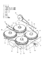
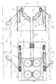
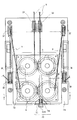
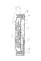
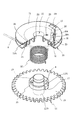
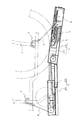
つぎに図面を参照しながら本発明の車椅子固定装置の実施の形態を説明する。図1は本発明の車椅子固定装置の一実施形態を示す要部斜視図、図2はその装置の全体平面図、図3はその装置の要部平面図、図4は図3のIV-IV 線断面図、図5はその装置の巻き取り機の要部分解斜視図、図6はその装置のフック収容部の斜視図、図7はその装置の使用状態を示す縦断面図である。
【0017】
最初に図2を参照して車椅子固定装置の全体を説明する。図2に示す車椅子固定装置Aは、自動車の荷台の後部側に設けられる後ケース1と、その後ケース1内に前後に移動自在に設けられるベース2と、そのベース2に取り付けられる巻き取り機構3、4と、後ケース1内に設けられるフック収容部5と、自動車の荷台の前部側に設けられ前ケース6と、その前ケース6内に取り付けられるワイヤガイド7およびフック収容部5とを備えている。巻き取り機構は前ワイヤ8を巻き取るための前側の巻き取り機構3と、後ワイヤ9を巻き取るための後側の巻き取り機構4とに分かれている。
【0018】
後ケース1は図4に示すように箱状の本体1aと、その上面を覆うカバー1bとからなる。ベース2は断面コ字状に形成されており、本体1aの底面上に前後に摺動自在に設けられている。ベース2の下面側には、巻き取り機3、4の要素であるモータ(図1の符号M参照)および減速機Gが取り付けられている。減速機Gとしてはウォーム減速機などの自己拘束型のものが用いられる。ベース2の上面側にはブラケット10が固定され、そのブラケット10に、図1および図3に示すように、左右一対の前ギヤ11の軸部12と、左右一対の後ギヤ13の軸部14がそれぞれ回転自在に支持されている。
【0019】
つぎに巻き取り機構3、4について説明するが、前後の巻き取り機構3、4は実質的に同じであるので、まず、前側の巻き取り機構3について説明する。なお前ギヤ11は単にギヤという。図5に示すように、ギヤ11は円盤状のギヤ部15の上下に上部軸12aと下部軸12bを突出させて一体にした形態を有する。さらにギヤ部15の上面には環状突起16が突設され、その環状突起16の外側に扇状突起17が一体に設けられている。なお上部軸12aには止め輪用の環状溝18が形成されており、ギヤ部15にはバネ係止孔19が形成されている。そして上部軸12aの周囲には、プーリ状のドラム20が回転自在に嵌合される。
【0020】
ドラム20は円盤状の上板21と、その中心に設けられる開口部22の内縁に沿って下方に突出する筒状の軸受け部23と、外周近辺に設けられる断面L字状のワイヤ巻き取り部24とを備えている。ワイヤ巻き取り部24の内面側は、上板21の下面と共にワイヤ8を係合するガイド溝24aとなっている。また軸受け部23とワイヤ巻き取り部24の間には、環状突起26が設けられており、その環状突起26の内側に前記ギヤ部15の扇状突起7と係合する扇状突起27が設けられている。さらに上板21にはバネ係止孔28と、ワイヤ8および索端金具8aを通すための開口部29が形成されている。開口部29はガイド溝24a内に連通している。
【0021】
なお図5は右前側の巻き取り機の場合を示しているが、ドラム20を左右共通にするため、開口部29は2ヶ所に設けられている。そしてそれらの開口部29同士は溝30で連通され、その溝30の中央部に索端金具8aを嵌合させるワイヤ係止孔30aが設けられている。溝30はガイド溝24aの底面と滑らかに連続するガイド壁31により囲まれている。
【0022】
ギヤ11とドラム20の間には、ドラム20をワイヤ8を巻き取る方向に付勢するためのバネ32が介在されている。バネとしてはネジリコイルバネや渦巻きバネなどが用いられる。バネ32の上端は、ドラム20のバネ係止孔28に係止され、下端はギヤ11のバネ係止孔19に係止される。そしてバネ32のコイル部は、組み立てたときに形成されるドラム20の軸受け部23とギヤ11の環状突起16の間の環状の空間内に収容される。
【0023】
上記のギヤ11、バネ32およびドラム20は、モータMおよび減速機Gと共に巻き取り機構3を構成している。それらを組み立てる場合、バネ32の上端および下端をそれぞれ対応するバネ係止孔28、19に係止させ、あらかじめバネ32にネジリ撓みを加えた状態でギヤ11の上部軸12aをドラム20の軸受け部23に嵌合させる。さらに上部軸12aの環状溝18に止め輪を嵌合させることにより、図3および図4に示すように組み立てられる。
【0024】
組み立てた状態では、ドラム20がバネ32の付勢力でワイヤ8を巻き取る方向、すなわち図5では反時計方向に付勢され、ドラム20の扇状突起27の側面がギヤ11の扇状突起17の側面に当接した状態で停止する。そしてドラム20は扇状突起27の他方の側面がギヤ11の扇状突起17の他方の側面に当接するまでの約1回転(たとえば300度)の範囲で回動自在である。ただしワイヤ8を送り出す方向、すなわち時計方向に対しては、ドラム20はバネ32の付勢力に抗しながら回転させることになる。
【0025】
図1および図3に示すように、左側のギヤ11およびそのギヤ11に対して所定の角度範囲で回動自在に設けられるドラム20およびバネは、右側の前ギヤ11の場合と実質的に同じである。ただし右側のドラム20にはワイヤ8が時計方向に巻き付けられるのに対し、左側のドラム20には、反時計方向にワイヤ8が巻き付けられる。そして右側のギヤ11と左側のギヤ11は同調回転するように互いに噛み合っており、右側のギヤ11の下部軸(図4の符号12b)に、前述の減速機Gの出力軸が連結されている。それにより1個のモータMおよび減速機Gにより、左右のギヤ11、11が同調して往復回転駆動される。それらは全体として前側の巻き取り機構3となる。後ワイヤ9を巻き取るための後側の巻き取り機構4についても、実質的に前側の巻き取り機と同じである。ただし後ギヤ13の場合は、左側の後ギヤ13の下部軸に減速機Gを介してモータMが連結されている(図4参照)。
【0026】
前後の巻き取り機構3、4は、前述のように共通のベース2に取り付けられており(図3参照)、そのベース2はネジ機構33により、前後に移動自在に構成されている。ネジ機構33は、たとえば後ケース1の本体1aに回転自在に、かつ軸方向に移動しないように取り付けたネジ34と、ベース2の下面に固定したナット35(あるいはベース2に直接形成した雌ネジ)とから構成することができる。それによりネジ34の頭部34aを回転させることにより、ベース2を前後に移動させることができる。なおネジ34にロック用のナットを別個に螺合させておくようにしてもよい。
【0027】
図3および図4に示すように、後ケース1の本体1aの前後の左右端近辺には、それぞれ後側のドラム20から延び出ているワイヤ9を案内するアイドルプーリ37、38が回転自在に収容されている。なお図4の符号38aはアイドルプーリ38を支持するブラケットである。前側のアイドルプーリ37は、前方に延びるワイヤ9を一旦後方に方向転換するもの(請求項1の方向転換部材)である。そして後側のアイドルプーリ38は、図2に示すようにワイヤ9の先端のフックFを車椅子に引っ掛けるために上向きに方向転換するためのものである。なお、ドラム20から前側のアイドルプーリ37に向かって延びるワイヤ9は、いくらか斜め外向きに拡がるように配索される。また本体1aの前側の中央部には、前側のドラム20から送り出されるワイヤ8を、前ケース6側に案内するためのアイドルプーリ39が回転自在に取り付けられている。各アイドルプーリ37、38、39はそれぞれ水平方向に配置された軸周りに回転自在に支持されている。後側のドラム20から送り出されるワイヤ9を一旦前向きに延ばしてアイドルプーリ(方向転換部材)37で方向転換させるのは、後側のドラム20から送り出されるワイヤ9の向きを前側のドラムから送り出されるワイヤ8の向きに合わせて、ベース2を前方に移動させたときに同時にワイヤ8、9の張力を緩めるためである。
【0028】
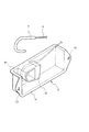
なお図3および図4に示すように、後ケース1の本体1aの左右の側部には、箱状のフック収容部5が設けられている。フック収容部5は図6に示すように、上方と側方が開放された箱状の形態を有し、上部端縁および側部の端縁にはそれぞれフランジ部40、41が設けられている。さらに側部のフランジ部41の両端には、後ケース1の本体1aに取り付けるための孔43が設けられている。さらに側壁の内面には、フックFを係合させるための突起45が突設されている。それによりフックFを使用しないときは、フックFをフック収容部5内に収容しておくことができる。
【0029】
つぎに図2を参照して前ケース6側を説明する。なお前ケース6と後ケース1に分離しているのは、図7に示すように、後ケース6は自動車の荷台に対して後側が低くなるように傾斜しているためである。前述の後ケース1の前部のアイドルプーリ39は、そのような傾斜している後ケース1から前ケース6に前ワイヤ8を案内するためのものである。
【0030】
図7に示すように、前ケース6についても、箱状の本体6aとその上に被せられるカバー6bとからなる。本体6a内には、垂直方向の軸心周りに回転自在に設けられるガイドドラム46、47が配置されている。ガイドドラム46、47はブラケット48により保持される軸49によって回転自在に支持される円筒状のドラムである。図2に示すように、それらのガイドドラム46、47およびブラケット48は前述のワイヤガイド7を構成しており、そのワイヤガイド7はセンター部分を通る2本の前ワイヤ8を外側に拡げるために斜め方向に配置されている。さらに前ケース6の前部の左右端近辺には、水平方向の軸49まわりに回転自在にガイドプーリ50が設けられている。前ワイヤ8はそれらのガイドプーリ50によって方向転換され、その先端のフックFが車椅子に引っかけられる。なお前ケース6の側方に設けられるフック収容部5は前述の後ケース1のフック収容部5と同じものである。
【0031】
つぎに上記のごとく構成される車椅子固定装置Aの使用方法を説明する。通常の状態では、各巻き取り機構3、4のモータMは、ドラム20にワイヤ8、9を巻き取る方向に回転した上で停止しており、各ワイヤ8、9はほとんどドラム20のワイヤ巻き取り部34に巻き取られている。そしてワイヤ8、9の端部近辺がドラム20から引き出され、図2および図6の想像線で示すように、その先端のフックFをフック収容部5の突起45に係止している。なおワイヤ8、9をドラム20からいくらか引き出すときは、ドラム20はバネ32の付勢力に抗して回転させることができるので、モータMは停止した状態でよい。さらにフックFを突起45に係止した状態では、バネ32の付勢力でワイヤ8、9に張力が加えられているので、フックFは突起45にしっかりと係合させることができる。
【0032】
つぎに図7に示すように車椅子Cを自動車の荷台に乗り込ませた後、ワイヤ8、9をバネ32の付勢力に抗しながらドラム20から引き出し、フックFを車椅子Cのフレームに引っかける。その場合も巻き取りドラム20がバネ32により巻き取り方向に付勢されているので、フックFを引っかけやすい。そのとき、ワイヤ8、9の長さが足らない場合は、モータMを逆回転させてドラム20を巻き戻し方向に回転させ、ワイヤ8、9をさらに引き出すようにする。
【0033】
ついでモータMを正転方向に回転させ、ドラム20上にワイヤ8、9を巻き上げる。その場合、ワイヤ8、9にある程度張力が生じると、図5におけるギヤ11のみが回転し、ドラム20は追従しない。そしてギヤ11の扇状突起17がドラム20の扇状突起27に係合した後、両者が一緒に回転する。それにより図7に示すように、前後のワイヤ8、9が強く引き込まれ、車椅子Cを固定する。その状態でモータMを停止させる。なお前側の巻き取り機構3の左右のギヤ11同士は噛み合っているので、左右の前側のワイヤ8、8にはほぼ均等の張力が働く。また同様に後側のワイヤ9、9同士にもほぼ均等の張力が働く。そのため車椅子Cは安定して固定される。固定している間は、車椅子Cに揺れなどの外力が加わっても、減速機Gの拘束作用でワイヤ8、9に弛みが生じない。
【0034】
ワイヤによる車椅子Cの固定を解除するには、モータMを逆方向に回転させ、ギヤ11を逆転させる。それによりドラム20はワイヤをほどき出す方向に回転させることができるようになる。そのためワイヤ8、9の張力でドラム20がいくらか回転し、ワイヤ8、9の張力が緩む。その状態でフックFを車椅子Cのフレームから外す。ギヤ11の回転角度が少ない場合は、そのままフックFをフック収容部5内の突起45に引っ掛けて、前述のようにバネ45の付勢力でその状態を維持させておくことができる。ギヤ11の回転角度が大きい場合は、モータMをいくらか正転させてワイヤ8、9をドラム20に巻き取り、その上でバネ32の付勢力に抗してワイヤ8、9をドラム20から引き出し、フックFを突起45に引っ掛ければよい。
【0035】
通常の操作では上記のようにベース1を前後に移動させる必要はない。しかし電気系統が故障したとき、あるいはモータMによるワイヤの巻き取りが強すぎて、フックFを車椅子Cのフレームから外すことが困難な場合は、図3のネジ機構33のネジ34を回転させてベース2を前進させる。ロックナットを設けている場合はロックナットを緩めた上でネジ34を回転させる。それにより4本のワイヤ8、9が全体的に緩み、フックFをフレームから容易に外すことができるようになる。フックFを外した後は、再びネジ34を回転させてベース2を後端まで移動させ、場合によりロックナットを効かせておく。なお電気系統が故障している場合には、ネジ機構33を用いて手動で車椅子の固定をすることも可能である。また、前ワイヤのみ、あるいは後ワイヤのみを緩めるようにしてもよいが、その場合は緩めなかったワイヤが車椅子を引いて車椅子Cがその方向に移動する可能性がある。したがって4本のワイヤ8、9の全体を緩めるようにするのが好ましい。
【0036】
上記の車椅子固定装置Aは、4本のワイヤ8、9を前後で別個の巻き取り機構3、4で巻き取り、固定するようにしているので、車椅子Cを前後に傾動させる方向の力が加わった場合でも、車椅子は傾動せず、安定して固定しておくことができる。またモータMおよび減速機Gでワイヤをドラム上に巻き取ってワイヤに張力を加えるので、ワイヤに張力を加える作業が容易であり、しかも単にバネの付勢力だけで巻き取る場合に比して巻き取り作業が確実である。さらに減速機Gを用いているので、緊張させたワイヤがその状態でロックされる。そのため別個にロック機構を設ける必要はない。
【0037】
上記の実施形態では、1個のベース2上に前後の巻き取り機構3、4を取り付けているが、前後別々のベースに取り付けるようにしてもよい。その場合はたとえば通常のネジと逆ネジとを1本のネジ棒に形成し、前後のベースを同時に互いに近づけたり離れたりするようにすることもできる。その場合は図3の逆転させるアイドルプーリ37は不要である。また前記の実施形態では左右のギヤ11同士を噛み合わせて互いに逆方向に回転するように構成し、それにより左右のドラム30を同調回転させるようにしている。しかし左右のギヤの間にアイドルギヤを介在させて両方のギヤを同じ方向に回転させるようにしてもよい。さらに1個の回転部材に2個のドラムをそれぞれ所定の角度範囲で回転自在に取り付けるようにしてもよい。さらに1個のドラムで左右のワイヤを巻き取るようにすることもできる。その場合は1個の回転部材に対して1個のドラムを所定の角度範囲で回転自在に設ければよい。
【0038】
また前記実施形態では各ワイヤ8、9はばらばらであるが、図2の想像線で示すように、右側の前後のフックF同士を右側の棒材52で連結し、左側の前後のフックF同士を左側の棒材52で連結するようにしてもよい。その場合は自動車の後部の開口近辺に立っている操作者が棒材52の端部を握って前後のフックFを同時に操作して車椅子のフレームに引っかけることができる。そのような棒材52はゴムないし合成樹脂などの可撓性を有するものを使用し、車椅子のフレームにフックFを固定した後、各ワイヤ8、9の引き操作を妨げないものとする。
【0039】
さらに前記実施形態ではアイドルプーリ、ガイドプーリあるいはガイドドラムでワイヤの向きを変えるようにしているが、コントロールケーブルの導管を用いてワイヤの向きを変えるようにしてもよい。
【図面の簡単な説明】
【図1】 本発明の車椅子固定装置の一実施形態を示す要部斜視図である。
【図2】 その装置の全体平面図である。
【図3】 その装置の要部平面図である。
【図4】 図3のIV-IV 線断面図である。
【図5】 その装置の巻き取り機の要部分解斜視図である。
【図6】 その装置のフック収容部の斜視図である。
【図7】 その装置の使用状態を示す縦断面図である。
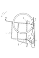
【図8】 従来の車椅子固定装置の一例を示す透視図である。
【図9】 その装置の使用状態を示す側面図である。
【図10】 従来の車椅子固定装置の他の例を示す平面図である。
【符号の説明】
A 車椅子固定装置
1 後ケース(ケース)
1a 本体
1b カバー
2 ベース
3 前側の巻き取り機構(前巻き取り機構)
4 後側の巻き取り機構(後巻き取り機構)
5 フック収容部
6 前ケース
7 ワイヤガイド
8 前ワイヤ
9 後ワイヤ
M モータ
G 減速機
11 ギヤ(駆動部材)
13 ギヤ(駆動部材)
12 軸部
15 ギヤ部
16 環状突起
17 扇状突起
19 バネ係止孔
20 ドラム
24 ワイヤ巻き取り部
26 環状突起
27 扇状突起
28 バネ係止孔
30a ワイヤ係止孔
32 バネ
33 ネジ機構(手動操作機構)
34 ネジ
35 ナット
F フック
37 アイドルプーリ(方向転換部材)
38、39 アイドルプーリ
46、47 ガイドドラム
50 ガイドプーリ
52 棒材 [0001]
BACKGROUND OF THE INVENTION
The present invention relates to a wheelchair fixing device. More particularly, the present invention relates to a device for fixing a wheelchair in an unfolded state loaded in a rear cargo compartment of an automobile, particularly a wheelchair in which a person is riding, using a wire.
[0002]
[Prior art]
This type of fixing device is disclosed in JP-A-9-131376. As shown in FIG. 8, the pair of left and
[0003]
In this fixing device, when the
[0004]
This fixing device is constructed such that the front and
[0005]
On the other hand, Japanese Patent Application Laid-Open No. 11-47193 discloses a wheelchair fixing device in which the front, rear, left and
[0006]
Since this wire locks each wire individually, it exerts a binding force against an external force that tilts the wheelchair back and forth. However, the restraining force of each wire differs depending on the initial winding amount of the wire, and it is difficult to balance the tension of each wire. In particular, when the initial winding of the wire is insufficient, a sufficient restraining force cannot be obtained even if the wire is locked. Therefore, it is necessary to check the tension of the wire before locking, which is inconvenient to handle.
[0007]
[Problems to be solved by the invention]
An object of the present invention is to provide a wire-type wheelchair fixing device that can exert a sufficient restraining force against tilting of the wheelchair in the front-rear direction and that is easy to handle restraint and release.
[0008]
[Means for Solving the Problems]
The wheelchair fixing device of the present invention includes a hook for hooking the front end of the wheelchair at the tip, a front wire for pulling the wheelchair forward and downward of the wheelchair, and a drum for winding the proximal end side of the front wire, A front winding mechanism having a motor that drives the drum to reciprocate and a self-restraining speed reducer that transmits the rotation to the drum by decelerating the rotation of the motor, and a hook that hooks the wheelchair on the rear side of the wheelchair. A rear wire for pulling downward, a drum for winding the proximal end of the wire thereafter, a motor for reciprocatingly driving the drum, and a speed reducer having a self-constraining property that decelerates the rotation of the motor and transmits it to the drum A rear winding mechanism having a case, a case fixed to the rear portion of the automobile, and the case is provided so as to be movable in the front-rear direction of the wheelchair. Base and to support the mechanism and the rear take-up mechanism takesWithThe front wire coming out of the drum of the front winding mechanism and the rear wire coming out of the drum of the rear winding mechanismExtending in the same direction in the front-rear direction of the base, and either one of the front wire and the rear wire extending in the same directionThe direction changing member that changes the direction of the tip of the wire and extends it in the opposite directionAnd a screw mechanism composed of a screw and a nut fixed to the lower surface of the base or a male screw directly formed on the base, and the motor cannot be driven by using the screw mechanism. Or when the electrical system is brokenThe baseFrom the baseWireButExtendingSame side ofInmanuallyMove to bring the hook F to the front and rear wires so that they can be removed from the wheelchair.be able toIt is characterized by that.
[0010]
Furthermore, a front wire and / or a rear wire are provided in a pair of left and right,The winding mechanism isA left drum and a right drum for winding the left and right wires respectively;Based on a motor that reciprocatingly drives one of the left and right drums, a speed reducer interposed between the motor and the one drum, and rotation of the speed reducerRotate the left and right drums in syncA pair of gears that mesh directly or through idle gearsAre preferably provided.
[0011]
Further, the winding mechanism is rotationally driven by the motor and the speed reducer.And fan-shaped projections are formed.Drive member and the drive memberFan-shaped protrusions that engage with the fan-shaped protrusions are formed, and these protrusions do not engageAngular rangeIn a circleIt can be pivoted,AndIt is preferable to include the drum for winding the wire and a spring for urging the drum with respect to the driving member in the winding direction of the wire. Further, the hook of the front wire and the hook of the rear wire are connected by a flexible bar, and the bar has a length that allows the hook to be hooked on the wheelchair by grasping its end. Those are preferred.
[0012]
[Operation and effect of the invention]
When restraining a wheelchair with the wheelchair fixing device of the present invention, the front wire is locked to the front side of the wheelchair, the rear wire is locked to the rear side of the wheelchair, and the front and rear windersStructureThe motor is driven to wind the wire. Thereby, the front wire pulls the front side of the wheelchair forward and downward, and the rear wire pulls the rear side of the wheelchair rearward and downward independently of the front wire. Therefore, even if an external force in the tilting direction is applied to the wheelchair, it does not move. Furthermore, the front and rear wires can be automatically wound by electric drive. Further winderStructureSince it is driven by a motor with a speed reducer, it has a locking action when it has finished winding. Therefore, there is no need for an operation for locking the wire, and there is no need to provide a separate locking mechanism.
[0013]
furtherThe winder before and after the aboveStructureAre mounted on the same baseBecauseBy moving the base in the direction in which the wires extend, the front and rear wires can be loosened simultaneously. Thus, even in an emergency situation in which the motor cannot be driven, the wire tension can be relaxed by manual operation and the wheelchair can be detached. If necessary, the wheelchair can be fixed manually.When a screw mechanism for manually operating the base back and forth is provided, by operating the screw mechanism, the base can be moved back and forth to loosen or tighten the wire.
[0014]
Further, a front wire and / or a rear wire are provided in a pair of left and right, and a wire winding machineStructureIn the case of a device provided with a left drum and a right drum and a mechanism for rotating the left and right drums in synchronization, only one motor and one speed reducer need be provided for the front and rear. Furthermore, the winding machine for the left and right wiresStructureCan be rolled up evenly.
[0015]
A hook is attached to the end of the wire, and a winding mechanism has a rotating member driven by a motor, a drum provided on the rotating member so as to be rotatable within a predetermined angle range, and the drum in the winding direction of the wire. When the hook is locked to a mating member such as a wheelchair frame, the wire is pulled out from the drum against the biasing force of the spring and the hook is hooked on the mating member. The wire is immediately tensioned by the rotation of the drum. Therefore, the wire hooking operation is easy. In addition, in the case of a device in which a hook that hooks the wheelchair on the end of the front wire or the rear wire and a bar that operates the hook are attached, the hook is held on the wheelchair frame by grasping one end of the bar. Can be stopped. Therefore, even when the front wire is locked from the rear part of the vehicle to the front side of the wheelchair, it can be easily locked.
[0016]
DETAILED DESCRIPTION OF THE INVENTION
Next, an embodiment of the wheelchair fixing device of the present invention will be described with reference to the drawings. FIG. 1 is a perspective view showing a main part of an embodiment of the wheelchair fixing device according to the present invention, FIG. 2 is a plan view of the whole device, FIG. FIG. 5 is an exploded perspective view of a main part of the winder of the apparatus, FIG. 6 is a perspective view of a hook accommodating portion of the apparatus, and FIG. 7 is a longitudinal sectional view showing a use state of the apparatus.
[0017]
First, the entire wheelchair fixing device will be described with reference to FIG. A wheelchair fixing apparatus A shown in FIG. 2 includes a
[0018]
As shown in FIG. 4, the
[0019]
Next, the winding
[0020]
The
[0021]
FIG. 5 shows the case of the winder on the right front side, but in order to make the
[0022]
A
[0023]
The
[0024]
In the assembled state, the
[0025]
As shown in FIGS. 1 and 3, the
[0026]
The front and rear winding
[0027]
As shown in FIGS. 3 and 4,
[0028]
As shown in FIGS. 3 and 4, box-shaped hook
[0029]
Next, the
[0030]
As shown in FIG. 7, the
[0031]
Next, a method of using the wheelchair fixing device A configured as described above will be described. In a normal state, the motor M of each winding
[0032]
Next, as shown in FIG. 7, after the wheelchair C is put on the loading platform of the automobile, the
[0033]
Next, the motor M is rotated in the forward direction to wind up the
[0034]
In order to release the fixation of the wheelchair C by the wire, the motor M is rotated in the reverse direction, and the
[0035]
In normal operation, it is not necessary to move the
[0036]
Since the wheelchair fixing device A is configured to wind and fix the four
[0037]
In the above embodiment, the front and rear winding
[0038]
In the above embodiment, the
[0039]
Further, in the above embodiment, the direction of the wire is changed by an idle pulley, a guide pulley or a guide drum, but the direction of the wire may be changed by using a conduit of a control cable.
[Brief description of the drawings]
FIG. 1 is a perspective view of an essential part showing an embodiment of a wheelchair fixing device of the present invention.
FIG. 2 is an overall plan view of the apparatus.
FIG. 3 is a plan view of an essential part of the apparatus.
4 is a cross-sectional view taken along line IV-IV in FIG.
FIG. 5 is an exploded perspective view of a main part of a winder of the apparatus.
FIG. 6 is a perspective view of a hook accommodating portion of the device.
FIG. 7 is a longitudinal sectional view showing a usage state of the apparatus.
FIG. 8 is a perspective view showing an example of a conventional wheelchair fixing device.
FIG. 9 is a side view showing a use state of the apparatus.
FIG. 10 is a plan view showing another example of a conventional wheelchair fixing device.
[Explanation of symbols]
A Wheelchair fixing device
1 Rear case (case)
1a body
1b cover
2 base
3 Front winding mechanism(Front winding mechanism)
4 Rear winding mechanism(Post-winding mechanism)
5 Hook housing part
6 Front case
7 Wire guide
8 Front wire
9 Rear wire
M motor
G reduction gear
11 Gear(Drive member)
13 Gear (Drive member)
12 Shaft
15 Gear part
16 Annular projection
17 Fan-shaped projection
19 Spring locking hole
20 drums
24 Wire winding part
26 Annular projection
27 Fan-shaped projections
28 Spring locking hole
30a Wire locking hole
32 Spring
33 Screw mechanism(Manual operation mechanism)
34 screws
35 nuts
F hook
37 Idle pulley (direction changing member)
38, 39 Idle pulley
46, 47 Guide drum
50 Guide pulley
52 Bar
Claims (4)
その前ワイヤの基端側を巻きるためのドラム20、そのドラムを往復回転駆動するモータMおよびそのモータの回転を減速してドラムに伝える自己拘束性を有する減速機Gを有する前巻き取り機構3と、
先端に車椅子の後側に引っかけるフックFを備え、車椅子を後方向かつ下方に引っ張るための後ワイヤ9と、
その後ワイヤの基端側を巻き取るためのドラム20、そのドラムを往復回転駆動するモータMおよびそのモータの回転を減速してドラムに伝える自己拘束性を有する減速機Gを有する後巻き取り機構4と、
自動車の後部に固定されるケース1と、
そのケースに対し、車椅子の前後方向に移動自在に設けられ、前記前巻き取り機構3および後巻き取り機構4を支持するベース2とを備えており、
前記前巻き取り機構3のドラム20から出てくる前ワイヤ8および後巻き取り機構4のドラム20から出てくる後ワイヤ9が前記ベースの前後方向において同じ向きに延びており、
それら同じ向きに延びている前ワイヤ8および後ワイヤ9のうち、いずれか一方のワイヤ9の先端側を方向転換して逆向きに延ばす方向転換部材37と、
ネジ34と、ベース2の下面に固定したナット35あるいはベース2に直接形成した雄ネジとから構成されるネジ機構33とをさらに有しており、
そのネジ機構33を用いることにより、前記モータが駆動できない非常事態や電気系統が故障している場合に、前記ベース2を、ベースからワイヤ8、9が延びているのと同じ側に手動で移動させて、前ワイヤ8および後ワイヤ9に前記フックFを車椅子から外しうる緩みをもたらすことができる、車椅子固定装置A。A front wire 8 for pulling the wheelchair forward and downward of the wheelchair, provided with a hook F hooked to the front side of the wheelchair C at the tip;
A front winding mechanism having a drum 20 for winding the proximal end side of the front wire, a motor M for reciprocatingly driving the drum, and a reduction gear G having a self-constraining property that decelerates and transmits the rotation of the motor to the drum. 3 and
A hook F hooked on the rear side of the wheelchair at the tip, and a rear wire 9 for pulling the wheelchair backward and downward;
Thereafter, a post-winding mechanism 4 having a drum 20 for winding the proximal end side of the wire, a motor M that drives the drum to reciprocate, and a speed reducer G that decelerates the rotation of the motor and transmits it to the drum. When,
A case 1 fixed to the rear of the car;
The case is provided so as to be movable in the front-rear direction of the wheelchair, and includes a base 2 that supports the front winding mechanism 3 and the rear winding mechanism 4 .
The front wire 8 coming out from the drum 20 of the front winding mechanism 3 and the rear wire 9 coming out from the drum 20 of the rear winding mechanism 4 extend in the same direction in the front-rear direction of the base,
A direction changing member 37 for changing the direction of the tip end of either one of the front wire 8 and the rear wire 9 extending in the same direction and extending in the opposite direction ;
A screw mechanism 33 including a screw 34 and a nut 35 fixed to the lower surface of the base 2 or a male screw directly formed on the base 2;
By using the screw mechanism 33, the base 2 is manually moved to the same side as the wires 8 and 9 are extended from the base in the case of an emergency in which the motor cannot be driven or an electric system is broken. Thus, the front wire 8 and the rear wire 9 can be loosened so that the hook F can be removed from the wheelchair.
その駆動部材の扇状突起17と係合する扇状突起27が形成されると共に、それら突起が係合しない角度範囲で回動自在に設けられ、かつ前記ワイヤ8、9を巻き取るための前記ドラム20と、
そのドラムを駆動部材に対してワイヤ8、9の巻き取り方向に付勢するバネ32とを備えている請求項1記載の車椅子固定装置A。The winding mechanism 3 and 4, together with the said Ru is rotated by the motor M and the speed reducer G, and the driving member 11, 13 fan-shaped projections 17 are formed,
Said drum for with fan projection 27 is formed to be engaged with the fan-shaped projections 17 of the drive member, they protrusions are rotatably disposed at an angle range that does not engage, and winding the wire 8 and 9 20 and
The wheelchair fixing device A according to claim 1, further comprising a spring 32 for urging the drum in a winding direction of the wires 8 and 9 with respect to the driving member.
Priority Applications (1)
| Application Number | Priority Date | Filing Date | Title |
|---|---|---|---|
| JP15011799A JP4294792B2 (en) | 1999-05-28 | 1999-05-28 | Wheelchair fixing device |
Applications Claiming Priority (1)
| Application Number | Priority Date | Filing Date | Title |
|---|---|---|---|
| JP15011799A JP4294792B2 (en) | 1999-05-28 | 1999-05-28 | Wheelchair fixing device |
Publications (3)
| Publication Number | Publication Date |
|---|---|
| JP2000333994A JP2000333994A (en) | 2000-12-05 |
| JP2000333994A5 JP2000333994A5 (en) | 2006-07-13 |
| JP4294792B2 true JP4294792B2 (en) | 2009-07-15 |
Family
ID=15489869
Family Applications (1)
| Application Number | Title | Priority Date | Filing Date |
|---|---|---|---|
| JP15011799A Expired - Fee Related JP4294792B2 (en) | 1999-05-28 | 1999-05-28 | Wheelchair fixing device |
Country Status (1)
| Country | Link |
|---|---|
| JP (1) | JP4294792B2 (en) |
Families Citing this family (2)
| Publication number | Priority date | Publication date | Assignee | Title |
|---|---|---|---|---|
| JP2005111069A (en) * | 2003-10-09 | 2005-04-28 | Autech Japan Inc | Wheelchair fixing device |
| JP2006239288A (en) * | 2005-03-07 | 2006-09-14 | Chuo Spring Co Ltd | Load fixing device |
-
1999
- 1999-05-28 JP JP15011799A patent/JP4294792B2/en not_active Expired - Fee Related
Also Published As
| Publication number | Publication date |
|---|---|
| JP2000333994A (en) | 2000-12-05 |
Similar Documents
| Publication | Publication Date | Title |
|---|---|---|
| CN1100684C (en) | Easy-to-use safety net device | |
| KR100569544B1 (en) | Seat belt system | |
| US6779842B2 (en) | Child automotive safety seat with integral seat belt tensioner | |
| CA2431627C (en) | Mobility aid securement for vehicles | |
| JP3890610B2 (en) | Longitudinal adjustment device for seats, especially automobile seats | |
| EP1223827A1 (en) | Belt shortening device | |
| JP4294792B2 (en) | Wheelchair fixing device | |
| CN1926014A (en) | Seat belt device | |
| JP3962243B2 (en) | Cargo fixing device | |
| JP2021004135A (en) | Winch device | |
| JP2005111069A (en) | Wheelchair fixing device | |
| JP4071600B2 (en) | Wheelchair fixing device | |
| JP4218580B2 (en) | Wheelchair fixing device | |
| JP3361634B2 (en) | Automotive guard net device | |
| JP4220135B2 (en) | Wheelchair fixing device | |
| JP2008228791A (en) | Wheelchair fixing device | |
| JPH1147193A (en) | Wheelchair locking device | |
| JP4218579B2 (en) | Wheelchair fixing device | |
| KR200403336Y1 (en) | a head rest | |
| JP2000333994A5 (en) | ||
| JP2005118073A (en) | Wheelchair fixing device | |
| JP2020192859A (en) | Webbing support device | |
| JP4185239B2 (en) | Wheelchair fixing device | |
| JP5454104B2 (en) | Wheelchair fixing device | |
| JPH04372434A (en) | Step for vehicle |
Legal Events
| Date | Code | Title | Description |
|---|---|---|---|
| A521 | Written amendment |
Free format text: JAPANESE INTERMEDIATE CODE: A523 Effective date: 20060526 |
|
| A621 | Written request for application examination |
Free format text: JAPANESE INTERMEDIATE CODE: A621 Effective date: 20060526 |
|
| A977 | Report on retrieval |
Free format text: JAPANESE INTERMEDIATE CODE: A971007 Effective date: 20080826 |
|
| A131 | Notification of reasons for refusal |
Free format text: JAPANESE INTERMEDIATE CODE: A131 Effective date: 20080909 |
|
| A521 | Written amendment |
Free format text: JAPANESE INTERMEDIATE CODE: A523 Effective date: 20081110 |
|
| A131 | Notification of reasons for refusal |
Free format text: JAPANESE INTERMEDIATE CODE: A131 Effective date: 20081209 |
|
| A521 | Written amendment |
Free format text: JAPANESE INTERMEDIATE CODE: A523 Effective date: 20090209 |
|
| TRDD | Decision of grant or rejection written | ||
| A01 | Written decision to grant a patent or to grant a registration (utility model) |
Free format text: JAPANESE INTERMEDIATE CODE: A01 Effective date: 20090310 |
|
| A01 | Written decision to grant a patent or to grant a registration (utility model) |
Free format text: JAPANESE INTERMEDIATE CODE: A01 |
|
| A61 | First payment of annual fees (during grant procedure) |
Free format text: JAPANESE INTERMEDIATE CODE: A61 Effective date: 20090409 |
|
| FPAY | Renewal fee payment (event date is renewal date of database) |
Free format text: PAYMENT UNTIL: 20120417 Year of fee payment: 3 |
|
| R150 | Certificate of patent or registration of utility model |
Free format text: JAPANESE INTERMEDIATE CODE: R150 |
|
| FPAY | Renewal fee payment (event date is renewal date of database) |
Free format text: PAYMENT UNTIL: 20120417 Year of fee payment: 3 |
|
| FPAY | Renewal fee payment (event date is renewal date of database) |
Free format text: PAYMENT UNTIL: 20130417 Year of fee payment: 4 |
|
| FPAY | Renewal fee payment (event date is renewal date of database) |
Free format text: PAYMENT UNTIL: 20130417 Year of fee payment: 4 |
|
| FPAY | Renewal fee payment (event date is renewal date of database) |
Free format text: PAYMENT UNTIL: 20140417 Year of fee payment: 5 |
|
| LAPS | Cancellation because of no payment of annual fees |