JP4292009B2 - Method for synchronized operation of a machine with a shaft driven by a single drive mechanism - Google Patents
Method for synchronized operation of a machine with a shaft driven by a single drive mechanism Download PDFInfo
- Publication number
- JP4292009B2 JP4292009B2 JP2002580095A JP2002580095A JP4292009B2 JP 4292009 B2 JP4292009 B2 JP 4292009B2 JP 2002580095 A JP2002580095 A JP 2002580095A JP 2002580095 A JP2002580095 A JP 2002580095A JP 4292009 B2 JP4292009 B2 JP 4292009B2
- Authority
- JP
- Japan
- Prior art keywords
- function
- axis
- basic axis
- axes
- basic
- Prior art date
- Legal status (The legal status is an assumption and is not a legal conclusion. Google has not performed a legal analysis and makes no representation as to the accuracy of the status listed.)
- Expired - Fee Related
Links
Images


Classifications
-
- G—PHYSICS
- G05—CONTROLLING; REGULATING
- G05B—CONTROL OR REGULATING SYSTEMS IN GENERAL; FUNCTIONAL ELEMENTS OF SUCH SYSTEMS; MONITORING OR TESTING ARRANGEMENTS FOR SUCH SYSTEMS OR ELEMENTS
- G05B19/00—Programme-control systems
- G05B19/02—Programme-control systems electric
- G05B19/18—Numerical control [NC], i.e. automatically operating machines, in particular machine tools, e.g. in a manufacturing environment, so as to execute positioning, movement or co-ordinated operations by means of programme data in numerical form
- G05B19/414—Structure of the control system, e.g. common controller or multiprocessor systems, interface to servo, programmable interface controller
- G05B19/4141—Structure of the control system, e.g. common controller or multiprocessor systems, interface to servo, programmable interface controller characterised by a controller or microprocessor per axis
-
- B—PERFORMING OPERATIONS; TRANSPORTING
- B41—PRINTING; LINING MACHINES; TYPEWRITERS; STAMPS
- B41P—INDEXING SCHEME RELATING TO PRINTING, LINING MACHINES, TYPEWRITERS, AND TO STAMPS
- B41P2213/00—Arrangements for actuating or driving printing presses; Auxiliary devices or processes
- B41P2213/70—Driving devices associated with particular installations or situations
- B41P2213/73—Driving devices for multicolour presses
- B41P2213/734—Driving devices for multicolour presses each printing unit being driven by its own electric motor, i.e. electric shaft
-
- G—PHYSICS
- G05—CONTROLLING; REGULATING
- G05B—CONTROL OR REGULATING SYSTEMS IN GENERAL; FUNCTIONAL ELEMENTS OF SUCH SYSTEMS; MONITORING OR TESTING ARRANGEMENTS FOR SUCH SYSTEMS OR ELEMENTS
- G05B2219/00—Program-control systems
- G05B2219/30—Nc systems
- G05B2219/42—Servomotor, servo controller kind till VSS
- G05B2219/42186—Master slave, motion proportional to axis
-
- G—PHYSICS
- G05—CONTROLLING; REGULATING
- G05B—CONTROL OR REGULATING SYSTEMS IN GENERAL; FUNCTIONAL ELEMENTS OF SUCH SYSTEMS; MONITORING OR TESTING ARRANGEMENTS FOR SUCH SYSTEMS OR ELEMENTS
- G05B2219/00—Program-control systems
- G05B2219/30—Nc systems
- G05B2219/50—Machine tool, machine tool null till machine tool work handling
- G05B2219/50218—Synchronize groups of axis, spindles
-
- G—PHYSICS
- G05—CONTROLLING; REGULATING
- G05B—CONTROL OR REGULATING SYSTEMS IN GENERAL; FUNCTIONAL ELEMENTS OF SUCH SYSTEMS; MONITORING OR TESTING ARRANGEMENTS FOR SUCH SYSTEMS OR ELEMENTS
- G05B2219/00—Program-control systems
- G05B2219/30—Nc systems
- G05B2219/50—Machine tool, machine tool null till machine tool work handling
- G05B2219/50229—Synchronize axis by simulating several virtual axis to control real axis
Abstract
Description
本発明は、単独駆動機構により駆動される複数の軸を備えた機械の同期化された運転を行うための方法に関するものであり、その際、軸は、いずれも付属する単独駆動機構により電子的な、時間的な基本軸関数に応じて相互に同期化され、駆動される。この種の機械は、特に搬送軸、並びに加工軸、例えばサーボモーターと駆動機構からなるサーボ駆動機構によって駆動される適切なローラーを備えている。ここでは、便宜上、単にその軸(サーボ軸)のみを取り上げる。 The present invention relates to a method for performing a synchronized operation of a machine having a plurality of shafts driven by a single drive mechanism, in which case the shafts are all electronically operated by a single drive mechanism attached thereto. In addition, they are synchronized with each other and driven in accordance with a temporal basic axis function. This type of machine comprises in particular suitable rollers driven by a conveying axis and a machining axis, for example a servo drive mechanism comprising a servo motor and a drive mechanism. Here, for convenience, only the axis (servo axis) is taken up.
この種の機械は、例えば、輪転機あるいはアーチ型印刷機械、紙加工機械、などの印刷機械、並びに梱包機械、生産ラインなどの製造機械などが想定できる。一般的にこの方法は、比較的規模の大きな、自動化された機械に投入され、それらの機械では、複数の、単独駆動機構により駆動される軸が、基本軸により相互に同期化される。 As this type of machine, for example, a printing machine such as a rotary press or an arch-type printing machine or a paper processing machine, a manufacturing machine such as a packing machine or a production line can be assumed. In general, this method is applied to relatively large, automated machines, in which a plurality of axes driven by a single drive mechanism are synchronized with one another by a basic axis.
このいわゆる“電子主軸”の原理は、素材ラインの加工機械では、最近はほとんどのものに用いられている。その際、該当する、付属する単独駆動機構により駆動される軸は、(付属する駆動機構の同期化により、あるいは上位に位置する制御機構を介して)上位に位置する時間的な基本軸関数に従い、それにより同期化される。基本軸関数は、例えば仮想の、すなわち電子的に発生させた、あるいは実際の基本軸のその時の位置との一致を行う。この関数は、例えばその時の位置の時間的な変化、すなわち基本軸の角度位置を再現する。しかしながらこの関数はまた、回転速度の時間的な変化、あるいはその他の基本軸のその時の位置と一致するパラメーターをも含む。特に、これは、電子的、時間的な期待値の連続である。従属するとは、これらの関連性において、該当する軸のところでの動きが、直接的に、あるいは基本軸を考慮した機械的な変換に応じる変換関数を介して、基本軸関数により導かれることを意味する。これにより歯車、板カム、オフセット、あるいは同様の機械的なエレメントが、電子的にエミュレートされる。 The principle of this so-called “electronic spindle” has recently been used in most materials line processing machines. In this case, the corresponding axis driven by the attached single drive mechanism is in accordance with the temporal basic axis function located at the upper level (by synchronization of the attached drive mechanism or via the higher-level control mechanism). , Thereby being synchronized. The basic axis function, for example, matches the virtual, electronically generated or actual basic axis position at that time. This function reproduces, for example, the temporal change of the position at that time, that is, the angular position of the basic axis. However, this function also includes parameters that are consistent with changes in rotational speed over time or other positions of the basic axis. In particular, this is a sequence of electronic and temporal expectations. Dependent means that in these relationships, movement at the relevant axis is guided by the basic axis function, either directly or through a conversion function that responds to a mechanical transformation that takes into account the basic axis. To do. This electronically emulates gears, plate cams, offsets, or similar mechanical elements.
ここで示した(自動化された)機械では、この種の機械的な変換、例えば歯車、カップリングなど多数のものが必要である。 The (automated) machine shown here requires a number of such mechanical transformations, such as gears, couplings and the like.
このためには、それぞれ付属する変換関数が、あらかじめ設定され、基本軸に関連した機械的な変換に応じて誘導されるこの種の軸は、それぞれ基本軸により電子的に誘導されることが知られている。軸の数が非常に多い場合、またそれに応じて駆動機構の数が多くなる場合には、ここで、関連する基本軸関数のあらかじめ設定された実行サイクルが理由で、時間的なジッタが、関連する軸の数との関係で、エラー伝搬の種類に応じてさらに加算される問題が生ずる。加算される合計誤差は、実行サイクルにより多くの軸が関係しているほど、その値は大きくなる。これに加えて、該当する軸のところでは、それぞれ該当する機械的な変換を行うためには、機械的、並びに技術的な負担はたいへん大きい。 For this purpose, it is known that each of these types of axes, in which the associated transformation functions are preset and are induced in response to mechanical transformations associated with the basic axes, are each electronically induced by the basic axes. It has been. If the number of axes is very large and the number of drive mechanisms accordingly increases, then the time jitter will be related because of the preset execution cycle of the relevant basic axis function. Depending on the number of axes to be added, there is a problem that further addition is performed according to the type of error propagation. The total error added increases as more axes are involved in the execution cycle. In addition to this, the mechanical and technical burdens are very large in order to perform the corresponding mechanical transformations at the corresponding axes.
ここに提示された発明の課題は、冒頭で記述した方法が、特に、調整を必要とする軸の数が多い場合に、修正を必要とする軸の同期化をかなりの程度で保証し、また同時に相対的にわずかな機械的負担により簡単な運転開始を可能にすることを示すことにある。 The problem of the invention presented here is that the method described at the beginning guarantees a considerable degree of synchronization of the axes that require modification, especially when the number of axes that require adjustment is large. At the same time, it is to show that it is possible to start a simple operation with a relatively small mechanical load.
この課題は、請求項1の特徴により解決される。本発明は、かなり正確な同期性を備えた軸 -つまり、全般的に基本軸関数によりあらかじめ与えられている期待値サイクルからの逸脱が少ない- ものにより駆動できるという長所を持つ。このために、機械面での負担を軽減し、運転開始をかなり軽減している。全体的にはそれにより、かなりの数の軸が、“電子的な軸”に従属し-同期化を維持しながら駆動される。 This problem is solved by the features of claim 1. The present invention has the advantage that it can be driven by an axis with fairly precise synchrony-i.e. less deviation from the expected cycle given in general by the basic axis function. For this reason, the load on the machine is reduced, and the start of operation is considerably reduced. Overall, this allows a significant number of axes to be driven, dependent on the “electronic axis” —while maintaining synchronization.
この長所は、次により達成される。すなわち、複数の軸であり、機械的な変換に応じているものが、少なくとも軸の一つのグループへと包括されることにより達成される。ここでは、ひとつのグループで、基本軸に対して共通の伝動を呈している軸に対応するものを含む。これらは、例えば同様の、あるいは適切な歯車変換を備えることが可能であり、適切なカップリング動作を備えることができ、共通の板カム比、あるいは前述の変換のコンビネーションを備えた軸グループであり得る。これらの軸に対して、これにより同様の機械的な変換を満たすものである。 This advantage is achieved by: In other words, a plurality of axes that respond to mechanical transformation is achieved by being included in at least one group of axes. Here, one group includes one corresponding to an axis exhibiting a common transmission with respect to the basic axis. These are, for example, shaft groups with similar or appropriate gear transformations, with appropriate coupling action, with a common plate cam ratio, or a combination of the aforementioned transformations. obtain. For these axes, this satisfies the same mechanical transformation.
軸の機械的な変換に対する機械的な負担、並びに加工負担は、本発明により激減する。これは、該当する軸を、電子的に、時間的に従属基本軸関数に従う軸のグループにまとめることにより、単独軸のところでの該当する変換が不要となる。電子的な図は、これにより機械的に実現したものに相当する。機械的なパラメーター/エレメントは、電子的なモデルにより直ちに再構成される。 The mechanical burden on the mechanical conversion of the shaft, as well as the machining burden, is drastically reduced by the present invention. This is because the corresponding axes are grouped into a group of axes that electronically and temporally follow the subordinate basic axis function, so that the corresponding conversion at the single axis becomes unnecessary. The electronic diagram corresponds to what is realized mechanically. Mechanical parameters / elements are immediately reconstructed by an electronic model.
一つのグループの軸は、-優先的に直ちに、また直接的に、すなわち他の基本軸の影響を受けずに-電子的、時間的な従属基本軸関数に従う。このことは、動作が、該当する軸の所で直接的、あるいは他の(電子的な)変換を介して時間的な従属基本軸関数から導かれることを意味している。従属基本軸関数は、同様に従属基本軸のその時の位置と一致する。上記に基本軸に関して記述したことは、適合する。 A group of axes-preferentially immediately and directly, ie without being affected by other basic axes-follow the electronic, temporal subordinate basic axis function. This means that the motion is derived from the time dependent elementary axis functions either directly at the relevant axis or via other (electronic) transformations. The dependent basic axis function likewise coincides with the current position of the dependent basic axis. What has been described above for the basic axis is relevant.
この従属化、つまり基本軸 -導かれた基本軸- -駆動という流れにより、先に示された軸のグループに対しては、単に軸の駆動のための従属基本軸関数が活用されるだけである。これは、現在の技術標準と比較して、かなりの簡素化である。現在の技術標準では、基本軸のみが、機械の全ての軸の駆動に対して基準を示すものとなっており、また変換は、例えば駆動レベルで、個々の軸に対して個別に実行されなければならなかった。この意味において、この多大な負担は、本発明により実質的に回避することができるか、若しくはかなり減少し、また上位に位置する変換により、複数の軸に対する従属主関数に投入される。 This dependency, that is, the basic axis-derived basic axis-drive flow, allows the group of axes shown above to simply utilize the dependent basic axis function for driving the axis. is there. This is a considerable simplification compared to current technical standards. In the current technical standards, only the basic axes provide a reference for the drive of all axes of the machine, and the conversion must be performed individually for each axis, for example at the drive level. I had to. In this sense, this enormous burden can be substantially avoided or reduced considerably by the present invention, and is put into the dependent main function for a plurality of axes by means of a higher-order transformation.
このために、従属基本軸関数は、基準となる基本軸関数とあらかじめ設定されている機械的な変換に該当する変換関数のひとつとを結び付けることにより形成される。変換関数においては、優先的に全ての情報が、任意の、若しくは必要な機械的な変換を介して導かれ/維持される。根本的には、指定された機械的な変換は、グループの全ての軸に対して共通である。これを踏まえて、個々の軸もまた、他の機械的な変換により運転されていることがあり得る。 For this reason, the dependent basic axis function is formed by connecting a basic axis function serving as a reference and one of conversion functions corresponding to a preset mechanical conversion. In the conversion function, all information is preferentially derived / maintained via any or necessary mechanical conversion. Fundamentally, the specified mechanical transformation is common to all axes of the group. In light of this, individual shafts can also be driven by other mechanical transformations.
変換関数は、その場合、基本軸関数の適切に、電子的に変換された変換規定であり得る。この変換関数は、機械的な変換に対応し、例えば歯車関数での歯車比に相当する。この点については、後に詳細について述べる。 The conversion function can then be an appropriately electronically converted conversion specification of the basic axis function. This conversion function corresponds to a mechanical conversion and corresponds to, for example, a gear ratio in a gear function. Details of this point will be described later.
いずれにせよ、時間的、電子的な基本軸関数と該当する変換関数とを結び付けることから、-この変換関数は、通常時間的なものではないが-、適切な、電子的、時間的な従属基本軸関数が導きだされる。この従属基本軸関数は、指定された情報を、軸のグループの機械的な変換に関連して保有している。 In any case, because the temporal and electronic fundamental axis functions are linked to the corresponding transformation function-this transformation function is not usually temporal-but has an appropriate electronic and temporal dependency. A basic axis function is derived. This subordinate basic axis function holds the specified information in relation to the mechanical transformation of the group of axes.
軸のひとつのグループに対する(これは、例外的に個々の軸でもあり得るが、主として複数の軸)包括的な従属基本軸関数は、単独軸の同期化を改善する。まず、駆動関数で、基本軸に関連して実現化サイクルに含まれるものの数が、全体的に減少する。軸で、本発明に基づいたひとつの従属基本軸関数、若しくは複数の従属基本軸関数に従うものは、基本的には常に、基本軸の技術水準に従った軸や、さらに補足的に機械的な変換により、個別に導かれなければならない軸よりも、軸の数は少ない。欠落する変換の数は、グループにまとめられる全ての軸の数量に匹敵し、グループの数だけおのずと減少する。このことから、通常、本発明を用いる場合、必要とされる、機械的な変換の数量は、技術水準ですでに存在する伝動のほんのわずかなものでしかないことが、明らかである。 A comprehensive subordinate basic axis function for a group of axes (which is primarily multiple axes, which can be exceptionally individual axes, however) improves single axis synchronization. First, the number of drive functions that are included in the realization cycle in relation to the basic axis is reduced overall. An axis that follows one subordinate basic axis function or a plurality of subordinate basic axis functions according to the invention is basically always an axis according to the state of the art of the basic axis, or more supplementarily mechanical. The number of axes is less than the axes that must be derived individually due to the transformation. The number of transformations missing is comparable to the number of all axes that are grouped together, and naturally decreases by the number of groups. From this it is clear that when using the present invention, the number of mechanical transformations required is usually only a fraction of the transmission already present in the state of the art.
包括的な変換関数で、グループの軸に関連して上位に位置し、機械的な変換の基準に応じて計算され、グループの全ての軸に対して上位に位置し、包括的であるものを用いることにより、技術水準と対比させて、単独変換の数量が、軸の所で、-上記に示した通り-欠落する。その場合であっても、-既に関与するサイクル時間を減少させることにより-かなり高い同期化が達成されるので、本発明は、二つの効果がある。 Comprehensive transformation function that is higher in relation to the group's axes, calculated according to the mechanical transformation criteria, and higher in position for all axes in the group By using, the number of single conversions is lost at the axis-as shown above-in contrast to the state of the art. Even so, the present invention has two effects, since a considerably higher synchronization is achieved—by reducing the cycle time already involved.
軸のグループに対して単に一度だけ計算を必要とする変換関数は、全ての軸に対して実質的に、同時に、包括的に用いることができる。またこれにより、軸の高い同期化であっても、なんら別の対策を行う必要なく、その反対に、-上記で示したように- 多くの単独変換が提供される。 A transformation function that only needs to be calculated once for a group of axes can be used for all axes substantially simultaneously and comprehensively. This also provides for many single conversions, as shown above, as opposed to the need for any other measures, even with high axis synchronization.
グループの駆動機構において、期待値サイクルの伝達を行うための技術的な対策は、本発明に基づく機械では、なんら支障なく使用されているので、このことに関して、実質的になんら高度な、機械的な負担が生ずるものではない。 The technical measures for the transmission of the expected value cycle in the group drive mechanism are used without any problem in the machine according to the invention, so that in this regard, virtually no advanced mechanical It does not cause a heavy burden.
軸の動きの正確さを維持するために、大きな帯域幅を備えた伝達プロトコールが良い。これは、少なくとも32ビットを確保するべきであり、また軸の動きの正確さが、伝達関数の影響を受けた場合であっても維持できるよう保証されるべきである。 A transmission protocol with a large bandwidth is good in order to maintain the accuracy of the movement of the shaft. This should ensure at least 32 bits and ensure that the accuracy of the axis movement can be maintained even when affected by the transfer function.
ここに提示した発明の際立った設計は、以下に示す下位概念の請求に記述する。 The prominent design of the invention presented here is described in the subconcept claim below.
基準となる、機械的な変換の個々の種類に応じて、変換関数の種類は、あらかじめ決定されている。変換関数が、機械的な変換により決定されている、基本軸の瞬間的位置に対する位相ずらし分である位置ずらしを、基本軸の瞬間的位置との比較で把握する場合、本発明は、単に一つの位置ずらしが、軸の一つのグループに対して必要となる多くの応用ケースに既に適している。変換関数は、基本としてコンスタントな、あるいは時間的に変化する位置ずらしを基本軸-その時の位置に加える変換規定により構成される。位置ずらしの基準とその時間的変化は、優先的に、自由選択によりあらかじめ設定することができる。例えば、基本としてコンスタントな位置ずらしは、長期間にわたり現れる可能性があり、また一方で位置ずらしは、関与する時定数の基準により変化する。従って、調整技術上、簡単に取り扱える位置ずらしを、機械的変換の多くが、モデル化することができる。 The type of conversion function is determined in advance according to the individual type of mechanical conversion that serves as a reference. When the conversion function grasps a position shift determined by mechanical conversion , which is a phase shift with respect to the instantaneous position of the basic axis, by comparison with the instantaneous position of the basic axis, the present invention is merely one. One misalignment is already suitable for many application cases where one group of axes is required. The conversion function is basically composed of a conversion rule that adds a constant or time-shifting position shift to the basic axis-position at that time. The position shift reference and its temporal change can be set in advance by free selection. For example, a fundamentally constant misalignment can appear over a long period of time, while the misalignment varies depending on the time constant criteria involved. Therefore, many of the mechanical transformations can model a position shift that can be easily handled in the adjustment technique.
補足的に、あるいは代替案として、次のことを備えている。すなわち、変換関数は、機械的な変換により決定されており、基本軸に関連して歯車比に対応した関数を含む。従って、変換関数は、基本的には、-コンスタントな、あるいは時間的に(上記を参照のこと)変化する-歯車ファクター-、つまり上記に示した、歯車比で、グループの全ての軸に対して均等に基準となるものを含む。従属基本軸関数は、従って実質的には、グループの軸に対する基本導軸であり、これは、(上位に位置する)基本導軸関数に関連して、上記で解説を行ったように歯車比を呈する。 In addition or as an alternative, it provides: That is, the conversion function is determined by mechanical conversion, and includes a function corresponding to the gear ratio in relation to the basic axis. Therefore, the conversion function is basically -constantly or temporally changing (see above) -gear factor--that is, the gear ratio shown above, for all axes in the group. That are equally standard. The dependent fundamental axis function is therefore essentially the fundamental derivative with respect to the group axis, which is the gear ratio as described above in relation to the fundamental derivative function (which lies above). Presents.
これ以外には、代替的、あるいは補足的に次のことを備えている。すなわち、変換関数は、機械的な変換により決定された、基本軸に関連して、板カム関数並びに/あるいはカップリング関数に適応した関数を含む。従って、このことは、上記に示したことに適応させ“電子的な”板カム/カップリングに対して適用する。 Other than this, the following is provided as an alternative or supplement. That is, the conversion function includes a function adapted to the plate cam function and / or the coupling function in relation to the basic axis determined by mechanical conversion. This therefore adapts to what has been indicated above and applies to "electronic" plate cams / couplings.
上記に示した設計例は、関数上の関連性があらかじめ与えられており、比較的簡単に電子的にモデル化されるという長所を有する。しかしながら、この構成では、-単独、あるいは組み合わせで-多数の、また実質的に、軸から指定された機械への機械的変換に対する通常の要求事項の全てを実現することができる。これにより、可能な制限を従属基本軸関数の誘導の方法に対して課しており、これにより、本発明は、実質的に全ての発生する応用ケースに対して適するものとなる。 The design example shown above has the advantage that it is given a functional relevance in advance and is relatively easily electronically modeled. However, with this arrangement, it is possible to fulfill all the usual requirements for mechanical conversion from a large number and substantially to a specified machine-alone or in combination. This imposes a possible limit on the method of derivation of the dependent fundamental axis function, which makes the present invention suitable for virtually all occurring application cases.
上位に位置し、グループ毎の従属基本軸のコンセプトは、手動式、並びに/あるいは微調整装置の基準に基づき形成された変換関数の微調整が存在する場合には、実質上、提示されている全ての応用ケースに用いることができる。この微調整もまた、本発明の定める意味では、グループの全ての軸の上位に位置する。これにより、示された微調整は、包括的であり、また代替案的、あるいは時間的に、グループの個々の軸に関係して、変換関数の、また異なる別の微調整を備えている。そして、従属基本軸の統一により、条件づけられる駆動機構の誤差は、相互に個々の駆動機構の所の微調整により、つまり個々の軸でその都度、補正される。これにより、事実上、発生する全ての状況において、その都度保証されるべき同期化が、保持される。 The concept of subordinate basic axes, located at the top, is effectively presented in the presence of manual and / or fine-tuning of the transformation function formed on the basis of the fine-tuning device criteria Can be used for all application cases. This fine adjustment is also positioned above all axes of the group in the sense defined by the present invention. Thereby, the fine-tuning shown is inclusive and includes alternative or temporally different fine-tuning of the transformation function, in relation to the individual axes of the group. Then, by unifying the subordinate basic axes, the conditioned drive mechanism errors are corrected by fine adjustment of the individual drive mechanisms with respect to each other, that is, with each individual axis. This preserves the synchronization that should be guaranteed each time in virtually every situation that occurs.
調整装置の基準に基づく微調整のためには、例えば、印刷機械における巻き上げ調整装置、ダンサー調整装置、引っぱり(張り)調整装置、あるいは見当調整装置などを備えている。 For fine adjustment based on the reference of the adjustment device, for example, a winding adjustment device, a dancer adjustment device, a pulling (tension) adjustment device, or a register adjustment device in a printing machine is provided.
上記に示した意味において、特に補足的な位置ずらしが備えられている。その位置ずらしは、一つのグループの軸の個々の駆動機構に対して伝達され、従属基本軸の基準に応じて発生する従属基本軸信号に影響を与えるので、該当する軸は、この位置ずらしの分だけ従属基本軸に対して移動をする。またこの位置ずらしは、実質的に自由選択により、-手動で、例えばタイピング、あるいは調整の基準に応じて-あらかじめ設定を行うことができる。 In the sense shown above, a supplementary position shift is provided. The position shift is transmitted to the individual drive mechanisms of one group of axes and affects the dependent basic axis signal generated according to the reference of the dependent basic axis. Move with respect to the subordinate basic axis. Further, this position shift can be set in advance by a substantially free selection--manually, for example, according to typing or adjustment criteria.
本発明の応用領域は、素材ラインの加工機械における見当調整である。この設計例は、請求項1の上位概念に基づく素材ラインの加工機械における見当調整のための方法に関するものである。この種の機械は、搬送ステーション、並びに加工ステーションを有しており、例えば駆動される適切なローラーを備えている。この関連性において、便宜上、単にその軸のみを取り上げる。 An application area of the present invention is register adjustment in a material line processing machine. This design example relates to a method for register adjustment in a material line processing machine based on the superordinate concept of claim 1. This type of machine has a transfer station as well as a processing station, for example with suitable rollers to be driven. In this connection, for convenience, only that axis is taken up.
この種の方法は、例えば輪転印刷機械、紙加工機械、あるいはアーチ型印刷機械において用いられており、既に処理済みの、若しくは印刷された紙ラインが、更に加工、若しくは印刷されることになっている場合(Insetting)、例えば紙ライン上に既に存在するプリントに対して、引き続き行われる加工工程は、精密に位置調整されている縦位置に従わなければならない。これにより、例えば、相前後して施された2つの印刷モチーフは、紙の上にあらかじめ決められている場所を覆うことができる。これを達成するためには、相互に作用する搬送軸、並びに加工軸が、相関的に相互に見当調整装置を介して修正される。 This type of method is used, for example, in rotary printing machines, paper processing machines, or arch type printing machines, and already processed or printed paper lines are to be further processed or printed. If (Insetting), for example, for a print already present on the paper line, the subsequent processing steps must follow a precisely aligned vertical position. Thereby, for example, two printing motifs applied one after the other can cover a predetermined place on the paper. In order to achieve this, the conveying axes that interact with each other as well as the machining axes are corrected relative to each other via a register adjustment device.
素材ラインの加工機械では、加工機械の軸、あるいは機械部品の軸が、相互に同期化された単独の駆動機構を備えており、またそれによりおおよそメカニズム的に基本軸(これに関しては、例えばSYNAX6、2000年のRexroth Indramat有限会社のドキュメント書類を参照のこと)を補う方法が、最近では一般的な原則となっている。これに加えて、該当する軸が(付随する駆動機構の同期化によって、若しくはこれより上位にある制御機構によって)上位に配置された時間的な基本軸関数に従い、これにより同期化される。従うとは、このような状況において、該当する軸での動きが、直接的にあるいは、(電子的な)変換を経て、基本軸関数により導かれることを意味する。基本軸関数は、例えば、仮想的、つまり電子的に生成された、あるいは実際の基本軸のその時の位置と対応する。これは、例えば、その時の位置の時間的推移、つまり基本軸の角度位置を再現することが可能である。しかしまたこれは、回転速度の推移や、あるいはまたその他の基本軸の瞬間位置と対応するパラメーターを包括することができる。
特に、これは電子的、時間的な期待値の連続である。
補足的に、複数の、見当に従って作動する軸は、基本軸関数とは対照的に、素材ラインの見当マークの走査結果に基づき修正される。これらは、軸のその時の位置、軸の回転速度、あるいは該当するパラメーターに応じて修正される。修正の程度は、見当マークの走査により決定される。見当マークは、-技術水準で一般的なように-例えば、印刷された状態のものが考えられ、光学的に走査される。
In material line processing machines, the axis of the processing machine, or the axis of the machine part, is provided with a single drive mechanism that is synchronized with each other, so that it is roughly mechanically the basic axis (for example, SYNAX6 Complementing the 2000 Rexroth Indramat Co., Ltd. document) has become a general principle recently. In addition to this, the relevant axes are thereby synchronized according to the temporal basic axis function arranged at the upper level (by synchronization of the associated drive mechanism or by a higher-level control mechanism). To follow means that in such a situation, the movement on the relevant axis is guided by the basic axis function, either directly or via a (electronic) transformation. The basic axis function corresponds, for example, to the current position of a virtual, ie electronically generated or actual basic axis. For example, the temporal transition of the position at that time, that is, the angular position of the basic axis can be reproduced. However, it can also encompass parameters corresponding to the transition of the rotational speed and / or other instantaneous positions of the basic axes.
In particular, this is a sequence of electronic and temporal expectations.
In addition, a plurality of axes operating according to registration are modified based on the scanning result of the registration marks on the material line as opposed to the basic axis function. These are modified according to the current position of the shaft, the rotational speed of the shaft or the corresponding parameters. The degree of correction is determined by scanning the register mark. The registration marks, as is common in the state of the art, are, for example, printed and can be scanned optically.
修正を必要とする軸が、個々の見当調整装置により修正されるということは、周知のことである。このことから、個々の軸とその調整装置を個別にパラメータ化し、修正動作や同期化を考慮して、その他の軸との最適化を行う必要性が生ずる。運転開始に際しての負担は、次のような理由で高い。すなわち、個々の見当の数量が多い運転状況は、さらに高くなり、機械的な負担と結びついており、結果的に経費も高くなる。しかしながら、修正を必要とする軸の同期化は、必ずしも常に満足する状態が得られるわけではない。これは、必然的に機械的、電子的な理由による逸脱状況が、個々の見当調整装置の間に生ずる可能性があるからである。このことが、ラインの張り具合の変動をを生じさせる可能性がある。 It is well known that the axes that need to be corrected are corrected by the individual registration devices. From this, it becomes necessary to individually parameterize each axis and its adjusting device, and to perform optimization with other axes in consideration of correction operation and synchronization. The burden at the start of operation is high for the following reasons. In other words, the operating situation with a large amount of individual registers is further increased and is associated with a mechanical burden, resulting in higher costs. However, the synchronization of the axes that require correction does not always give a satisfactory condition. This is necessarily because deviations due to mechanical and electronic reasons can occur between the individual registration devices. This can cause fluctuations in the tension of the line.
さらに、一つの見当調整装置を、いくつもの軸に対して同時に影響させることが知られている。このためには、個々の軸において、つまり該当する駆動機構において、/該当するエレメントの該当する制御において、例えばローラーが、-個別の修正信号を伝達し、そしてそこで該当する個別の修正動作に切り替えられる。このための負担は、修正されるべき軸の数により非常に増加するので、この方法は、修正を必要とする軸が多いものに対しては、-一般的にそうであるように-適していないか、あるいは制約を加えてのみ使用が可能である。またここでは、修正信号の伝達に際してサイクル時間が大きすぎる結果、同期化の問題が生ずる。 Furthermore, it is known that a single register adjustment device affects several axes simultaneously. For this purpose, in each axis, ie in the relevant drive mechanism / in the relevant control of the relevant element, for example, the roller transmits an individual correction signal and then switches to the corresponding individual corrective action. It is done. The burden for this increases greatly with the number of axes to be modified, so this method is suitable-as is generally-for those with many axes that require modification. Can be used only with or without restrictions. Here, too, the cycle time is too long when the correction signal is transmitted, resulting in a synchronization problem.
ここに提示された発明の課題は、冒頭で記述した方法が、特に、調整を必要とする軸の数が多い場合に、修正を必要とする軸の同期化をかなりの程度で保証し、また同時に相対的にわずかな機械的負担により簡単な運転開始を可能にすることを示すことにある。 The problem of the invention presented here is that the method described at the beginning guarantees a considerable degree of synchronization of the axes that require modification, especially when the number of axes that require adjustment is large. At the same time, it is to show that it is possible to start a simple operation with a relatively small mechanical load.
この課題は、請求項1の特徴により解決される。 This problem is solved by the features of claim 1.
本発明は、わずか一つの見当調整装置により、任意の数の軸を同期的に調整できるという長所を備えている。これにより、機械的な負担は軽減され、また運転開始は、遥かに簡単なものとなる。本発明に基づく見当調整のための方法は、これらの長所を保持しながら、おのずと修正動作の同期化の程度を高める。 The present invention has the advantage that any number of axes can be adjusted synchronously with only one register adjustment device. This reduces the mechanical burden and makes starting operations much easier. The method for register adjustment according to the present invention naturally increases the degree of synchronization of corrective actions while retaining these advantages.
これらの長所は、1回の共通の走査から、修正を必要とするいくつもの軸に対する、共通の、特に時間的な修正関数を導き出すことにより、達成される。これらの修正関数に、見当に従う軸グループの全ての軸で、見当の修正に呼応するものが、従う。その結果として、グループの全ての軸に関して、総合的な修正関数における全ての修正動作の全情報が、含まれている。見当に従う軸のグループは、一つの共通の見当修正装置により修正され、つまり同一の見当調整と同一の走査に適応する軸を既に包括している。これらは、関連する/非断続的な素材ラインの所の軸である。輪転式印刷機では、一つの加工タワーの幾つかの、あるいは全ての軸が、例えば印刷タワーであったり、幾つかの異なる加工タワーで、素材ラインが切離されていないか、/あるいは中断されていない加工タワーの軸であったりする。 These advantages are achieved by deriving a common, especially temporal correction function for a number of axes that need correction from a single common scan. These correction functions are followed by all axes in the axis group that follow the register that respond to the register correction. As a result, all information of all corrective actions in the overall corrective function is included for all axes of the group. The group of axes according to the register already includes axes that are modified by one common register correction device, i.e. adapted to the same register adjustment and the same scan. These are the axes at the relevant / non-intermittent material line. In a rotary press, some or all axes of one processing tower are, for example, printing towers, or several different processing towers, the material lines are not cut off and / or interrupted. It may be the axis of the processing tower that is not.
単に見当調整装置の指示に応じて計算されており、グループの全ての軸に対して統一的である総合的な修正関数を活用することにより、現在の技術レベルでは、かなりの数の見当の調整が不要となる。その場合、しかしながら、同期化に関してはかなり高い程度で達成することができるので、本発明は、二重の利用効果を有する。 A significant number of registration adjustments at the current technical level by leveraging a comprehensive correction function that is simply calculated according to the instructions of the registration adjuster and is uniform for all axes of the group Is no longer necessary. In that case, however, the present invention has a double utilization effect, since it can be achieved to a much higher extent with respect to synchronization.
-多くの軸を含むことが可能な-軸の一つのグループに対して単に一台だけの見当調整装置を活用する場合であっても、自動的にかなり高い程度で同期化が保証される。それは、単に、一つの修正関数が、-並びに、それにより修正信号が- グループの全ての軸に対して用いることができるからである。このことから、グループの軸に対して単に一つの信号だけを伝達することができる。一度確定された修正関数は、全ての軸に対して同時に、また包括的に用いられ、これにより、そのために何ら別の事前策を行う必要なく、おのずと高い割合での調整動作の同期性が、修正によって提供される。 -Many axes can be included-Even if only one register adjuster is utilized for a group of axes, synchronization is automatically guaranteed to a very high degree. That is simply because one correction function can be used for all axes of the group-as well as the correction signal. Thus, only one signal can be transmitted to the group axis. Once the correction function is established, it is used for all axes simultaneously and comprehensively, so that it is not necessary to take any other precautions for this purpose, and the synchronism of the adjustment operation at a high rate is naturally Provided by modification.
本発明により、数多くの軸を単に一つの見当調整装置の指示により、高い精度での同期化を保ちながら調整することが、初めてできるようになる。この調整動作は、数多くの軸に対して、一つの見当調整装置により算出され、また次に全ての軸に対して用いることができ、そして実質的に、同時にこれらの軸に対して伝達されることが可能である。 According to the present invention, it becomes possible for the first time to adjust a large number of axes while maintaining high-accuracy synchronization by simply instructing one register adjusting device. This adjustment motion is calculated for a number of axes by a single register adjuster and can then be used for all axes and transmitted to these axes substantially simultaneously. It is possible.
ここに提示した発明の際立った設計は、以下に示す下位概念の請求に記述する。 The prominent design of the invention presented here is described in the subconcept claim below.
修正動作は、修正関数が、主として単に基本軸関数の修正を含む場合、並びにそれらの修正関数が、見当の修正として行われる場合、直接的に行われ、そのため迅速に該当する軸に提供される。修正信号の利便的で、迅速な活用を行うために、これらは、かなりわずかな計算容量、特にわずかな計算負荷により算出される。 The corrective action is done directly if the corrective function mainly involves simply correcting the basic axis functions, as well as if the corrective functions are made as register corrections, and thus are quickly provided to the appropriate axis. . In order to make convenient and quick use of the correction signals, they are calculated with a very little computing capacity, in particular a little computing load.
基本軸関数を備えた修正関数が、補足的に、時間的な見当結果-基本軸関数と結びつく場合は、これらの連携は、見当調整装置の関数の範囲内で、中心的に、包括的に行われ、該当する軸に対して見当結果-基本軸関数として伝達される。この種の見当結果-基本軸関数の一つに、個々の軸は、従って事実上直接的に、また即座に従う。その場合、高い計算負荷と結びついている周辺部への伝達を個々の軸に対して行う必要はない。見当結果-基本軸関数は、従って、事実上個々の軸に対する全てのデータを包括的な信号として有している。これは、あくまで作動可能な状態とするための技術的な予防的措置と基本軸関数の伝達を通常行わなくてはならないからであり、これは発明に基づく方法に対して、当然の解決策であり、この方法は、なんら支障なく、存在する駆動機構/調整機構に組み込むことができる。二つの基本軸関数があるが、それはつまり変更されていない基本軸関数であり、また見当結果-基本軸関数であるが、これに対しては、基本的には計算キャパシティと伝達キャパシティが、既に存在している。 If the correction function with the basic axis function is supplementarily linked to the temporal register result-the basic axis function, these linkages are central and comprehensive within the scope of the function of the register adjuster. Done and transmitted to the relevant axis as a register result-basic axis function. This kind of register result-one of the basic axis functions, the individual axes thus follow directly and immediately in effect. In that case, it is not necessary for the individual axes to transmit to the periphery, which is associated with a high computational load. The register result-basic axis function thus has virtually all the data for the individual axes as a comprehensive signal. This is because technical precautionary measures and basic axis functions must be normally transmitted in order to make the system ready for operation. This is a natural solution to the method based on the invention. Yes, this method can be incorporated into existing drive / adjustment mechanisms without any hindrance. There are two basic axis functions, that is, the basic axis functions that have not been changed, and the result-basic axis function, but for this, basically the calculation capacity and the transfer capacity are Already exists.
予想され得る、若しくは見当される(つまり、見当調整の範囲内で導き出される)逸脱状況の種類に応じて(その程度は、見当から素材ラインが流れるだけの程度のものであり、これは見当マークによりあらかじめ与えられたものと比較しての逸脱の程度である)修正関数の種類を選択することができる。 Depending on the type of deviation situation that can be anticipated or registered (ie, derived within the scope of registration adjustment) (the extent is just enough to flow the material line from the registration, this is the registration mark) The type of correction function (which is the degree of deviation compared to that given in advance) can be selected.
修正関数が、見当マークを走査することにより決定されるひとつの位置ずらしを、基本軸の瞬間位置との比較で把握する場合、本発明は、既にかなり多くの応用ケースがある。それらにおいては、逸脱状況が実質上コンスタントであるのもある。修正関数は、従って、原則として、ある一定の、あるいは見当マークの走査による程度に基づいて変化する位置ずらしにより構成される。ひとつの見当結果-基本軸関数は、この場合、あるコンスタントな、または、優先的に時間的にどちらかというとゆっくりと変化する基本軸の逸脱状況を有している。 In the case where the correction function grasps one position shift determined by scanning the register mark by comparison with the instantaneous position of the basic axis, the present invention already has many application cases. In those cases, the departure situation is substantially constant. The correction function is thus constituted in principle by a displacement that varies according to a certain or degree of scanning of the registration mark. One register-basic axis function has in this case a constant or deviating basic axis situation that changes preferentially in time, rather slowly.
補足的に、あるいは二者択一的に、次のようなものがある。すなわち、修正関数は、見当マークの走査により決定された、歯車比に関連し、基本軸に対応した関数を包括する。これは、単に修正動作を把握するだけの修正関数の場合に、やはりコンスタントな可能性のある歯車比に応ずるか、あるいは走査の程度に基づき、時間的に変化する。請求項3の場合、これは見当結果-基本軸関数で、(上位に配置されている)基本軸関数の歯車比から導きだされるものに応ずる。 Supplementary or alternatives include the following: That is, the correction function is related to the gear ratio determined by scanning the registration mark, and includes a function corresponding to the basic axis. In the case of a correction function that merely grasps the correction operation, this also changes with time depending on the gear ratio that may be constant or based on the degree of scanning. In the case of claim 3, this is the register result-basic axis function, which corresponds to that derived from the gear ratio of the basic axis function (placed at the top).
ここに示した設計により、簡素化、つまり修正関数を導くわずか2つの方法に対する可能な制限は、時間的な見当結果-基本軸関数を備えており、これにより本発明は、事実上、考え得る全ての活用ケースに対して適正を有する。 With the design presented here, the simplification, a possible limitation to only two ways of deriving the correction function, provides a temporal register-basic axis function, which makes the present invention virtually conceivable Appropriate for all use cases.
場合によっては、実質的に見当に従っている軸の中央領域において、-素材ラインの縦方向に関して-走査が行われることによって、一つのグループの軸間に残存する逸脱状況が、軽減する。場合によっては残存する逸脱状況は、基本的には、-素材ラインの縦方向を見た場合-継続的な経過、つまりこれらは、走査箇所、若しくはセンサーの所ではゼロである。これは、見当調整が、このセンサーに関しているからである。縦方向で測定した場合は、これらは、基本的には、かなりモノトーンであり、またセンサーの所でその信号を変える。この場合、示された走査箇所が、走査を行った場合にグループの軸の所での個々の逸脱状況を実質的に最も小さくし、また同時に該当する期待値の個々の軸の誤差の合計が最も小さくなる場所である。 In some cases, the remaining deviation between one group of axes is mitigated by scanning in the central region of the axis that is substantially in register, with respect to the longitudinal direction of the material line. In some cases, the remaining deviating situation is basically—when looking at the longitudinal direction of the material line—continuous progress, ie these are zero at the scanning location or at the sensor. This is because the registration adjustment is related to this sensor. When measured in the longitudinal direction, these are basically fairly monotone and change their signal at the sensor. In this case, the indicated scan point substantially minimizes the individual deviation situation at the group axis when the scan is performed, and at the same time the sum of the individual axis errors of the corresponding expected value. The smallest place.
特に、輪転式印刷機械でのインセッティング応用では、単に搬送軸のみを包括する一つのグループを備えていることを提案する。すると、修正関数/見当結果-基本軸関数は、グループの全ての搬送軸に対して基準となり、本発明に基づき、多大な(grosser)同期化により修正される。これは、搬送軸の加工軸に対比させたかなり詳細で、共通の修正へと導く。 In particular, it is proposed that an insetting application in a rotary printing machine has a single group that includes only the transport axis. The correction function / registration result-basic axis function then becomes the reference for all transport axes in the group and is corrected by gross synchronization in accordance with the present invention. This is quite detailed compared to the machining axis of the transport axis and leads to a common correction.
発明に則した見当調整での処理のより高い正確性を達成するために、補足的に、ひとつのあらかじめ決めた、計算負荷の点からも/計算容量の点からも簡単な、修正を加工軸で、グループの見当修正の観点から、搬送軸に対応するものに対して行うことを提案する。ここでは、上記に示した該当する軸の詳細を適切であると考える。この対策により、補足的な、簡単に実現できる自由度が調整システムにもたらされる。この意味で、一つの簡素化された修正は、ほとんどのケースに対して、場合によってはまだ生ずる逸脱状況を調整するために十分であると思われる。真にこの見当調整の場合では、見当マークによりあらかじめ示された場所による加工の一致に対する要求は、かなり高い。ここに示した設計は、簡単な方法で、この一致の精度をより改善することができる。その場合、多くの加工軸に対して実質的に同じである逸脱状況は、除去される。しかしまた、異なる加工軸に対して多様である可能性のある逸脱状況もまた、除去される。後者は特に、場合によっては残存している逸脱状況で、センサーから加工軸までの距離によって、生ずると思われるものである(上記において、この点について記述したことに則して)。 In order to achieve a higher accuracy of the process with the registration adjustment according to the invention, it is supplementary to make a simple modification from the point of calculation load / capacity in terms of a predetermined process axis. Therefore, from the viewpoint of correcting the group registration, it is proposed to do this for the one corresponding to the transport axis. Here, the details of the relevant axes shown above are considered appropriate. This measure gives the adjustment system a complementary, easily realizable degree of freedom. In this sense, one simplified correction seems to be sufficient for most cases to adjust for deviations that still occur. In the true case of this registration adjustment, the demand for matching of machining according to the location indicated in advance by the registration mark is quite high. The design shown here can improve this matching accuracy in a simple way. In that case, deviation situations that are substantially the same for many machining axes are eliminated. However, deviation situations that can be varied for different machining axes are also eliminated. The latter is particularly likely to occur due to the distance from the sensor to the machining axis in some cases of remaining deviations (in line with what has been described above).
上記に定める意味での簡素化され、効果的な修正は、素材ラインの縦ユニットごと、並びに走査箇所に対する縦方向の距離の修正が必要な加工軸に対する縦方向のエラーを算出し、基本的には、縦方向のエラーと縦方向の距離の積により、該当する加工軸の修正が形成される。通常、素材ラインは、加工の後に個々の製品を分けるので、素材ラインが、個々の製品で、あらかじめ設定した製品長さに分けることを提案する。その際、縦方向のエラーは、製品の長さごとに算出され、該当する加工軸の修正は、基本的には製品の長さ毎に縦方向のエラーと縦方向の距離/製品の長さの商から積を形成する。本発明は、必要とされる計算能力/計算容量の観点から簡素化される。このことは、逸脱状況が、縦方向の長さを対象としているので、必然的に通常、より優れた一致(前述を参照)をもたらす。製品の長さは、いずれにせよ加工軸に対して基準となる大きさであるので、適切な修正の算出と変換は、簡単に、また詳細に行うことができる。 Simplified and effective correction in the sense defined above basically calculates the vertical error for each vertical unit of the material line and the machining axis that requires correction of the vertical distance to the scanning location. The correction of the corresponding machining axis is formed by the product of the vertical error and the vertical distance. Usually, the material line divides each product after processing, so it is suggested that the material line be divided into product lengths set in advance for each product. At that time, the vertical error is calculated for each product length, and the correction of the corresponding machining axis is basically based on the vertical error and the vertical distance / product length for each product length. The product is formed from the quotient of The present invention is simplified in terms of required computing power / computed capacity. This inevitably usually results in a better match (see above), since the departure situation covers the length in the vertical direction. In any case, since the length of the product is a reference size with respect to the machining axis, calculation and conversion of appropriate correction can be performed easily and in detail.
上に示した、補足的な修正は、複数の、修正する必要がある加工軸が、請求項1に基づき一つのグループを形成することにより実現される。これにより、必要とされる修正に関する計算の回数は減少する。-通常、一つのグループ、あるいは複数のグループにまとめられる軸の数だけに、減少する。 The supplementary correction shown above is realized by forming a plurality of machining axes that need to be corrected into one group according to claim 1. This reduces the number of calculations related to the required correction. -Usually reduced to the number of axes that can be combined into one group or multiple groups.
該当する修正を伴う一つのグループに対してのこの関連性により、本発明の全ての長所を有する中心的構造が、形成される。この中心的構造は、他のグループに対して下位構造を成すことができる。そして加工軸は、多くのグループに分散することができる。基本的には、一つのグループ内での逸脱状況は、小さな値に留まる。 This relevance to a single group with the appropriate modifications forms a central structure with all the advantages of the present invention. This central structure can be subordinate to other groups. The machining axes can be distributed in many groups. Basically, deviations within a group remain small.
少なくとも、見当に呼応する軸で、時間的に基本軸関数が従うものがある場合、方法の考えうる容量は、完全に活用される。さらに、二つ、若しくは複数の基本軸関数があり、これらの関数は、システムの中に内蔵されており、またそれぞれ属している軸により活用される。つまり、補足的な軸は、ある基本軸関数(若しくは見当結果-基本軸関数)に従う。 If there is at least an axis that corresponds to the register and the basic axis function follows in time, the possible capacity of the method is fully utilized. In addition, there are two or more basic axis functions, which are built into the system and are used by the respective axis. That is, the supplementary axis follows a certain basic axis function (or registration result-basic axis function).
本発明は、解説図に示した設計プランを用いて、より詳細に説明される。 The present invention will be described in more detail using the design plan shown in the explanatory diagram.
以下に、特になにも付記されていない場合は、全ての図面は、常に全ての形状に関するものである。 In the following, unless otherwise noted, all drawings always relate to all shapes.
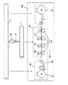
図1は、機械138における前述の発明に基づく基本軸設計の原理を図解により示したものである。上位に位置する基本軸Lから、微調整伝動装置モジュール107を備えた伝動装置関数106を介して従属基本軸Fが導かれる。この従属基本軸は、軸102、110、111のグループ117に影響を与える。これらは、示された例では、素材ライン(素材が長く連続したもの)144に対する加工機械の中の加工軸である。素材ライン144は、搬送軸145により搬送を促される。補足的に、巻き出し装置141と巻き取り装置142を備えている。巻き出し装置141と巻き取り装置142に対する駆動機構の軸である搬送軸145は、直接的に基本軸Lにより、場合によってはその間に接続されている単独主機構、つまり該当する機械的な変換機能により導かれる。搬送方向140には、加工ステーションが、接続されており、引っぱり調整/ライン貯まり部143が用意されている。これにより、例えばダンサー調整装置と接続されることも可能である。伝動装置モジュール106、若しくは微調整伝動装置モジュール107は、製品の形状に応じてパラメーター化される。これにより、製品の形状が変更となった場合には、簡単に基準となる機械部品の適切なパラメーター化により、全体的に同期化することができるので、軸の動きは、個々の製品の形状と一致する。
FIG. 1 illustrates the principle of basic shaft design based on the above-described invention in the
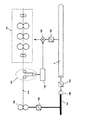
詳細については、ここに提示されている発明の一般かされた設計例は、図2に示されている。 For details, a generalized design example of the invention presented herein is shown in FIG.
ここでは、本発明の具体的な方法を用いた調整構造/期待値サイクルの形成のパーツが、図解により示されている。ここに示した概略図は、複数の軸102、110、111を備えた機械138のパーツである。前述の記述では、これらの軸という概念では、付属する結合部分/付属するステーション部分で、駆動機構(駆動調整装置、モーター、歯車)並びに適切なローラー、あるいはその他の回転装置、もしくは駆動機構により駆動される機械部品などからなるものを意味している。これらは、機械の単独エレメントであり、それらは本発明により相互に同期化され駆動される。以下には、このことから便宜上、軸のみを対象とし述べる。記述では、基本軸L(基本軸)とF(従属基本軸)が、区別されている。ここでは、(実際の、あるおは仮想の)基本軸従属が問題となる。これは、該当する基本軸のその時の位置、若しくは適切なその時の位置により一致するパラメーターの(多くの場合、不連続な)時間的な変化である。
Here, the parts of the adjustment structure / expectation cycle formation using the specific method of the present invention are shown by way of illustration. The schematic shown here is a part of a
(単独)軸102、110、111は、以下のように、電子的、時間的な基本軸関数の基準に基づき駆動される。 The (single) axes 102, 110, 111 are driven on the basis of electronic and temporal basic axis function criteria as follows.
基本軸L(これは適切な期待値の連続である)は、基本軸関数を発するための規則的な動きをする。基本軸Lは、また実質的に直接的にこれに接続されている機械軸139に影響を与える。これは、直接的、あるいは付属する、例えば個々の機械的な基本軸Lの変換を介して行われる。 The basic axis L (which is a succession of appropriate expectation values) has a regular movement to emit the basic axis function. The basic axis L also influences the mechanical axis 139 connected to it substantially directly. This can be done directly or via an associated, for example, transformation of the individual mechanical basic axis L.
図1に示した調整の構造のフローチャートは、終始基本軸Lから導かれ、あらかじめ設定された方法により基本軸Lにより同期化される。このためには、基本軸関数が、基本軸Lの後に配置されている基本軸118のひとつへ変換され、それに基づき、基本軸サイクル122の基準が発信される。代替方法として、基本軸サイクル122は、実際の基本軸119によっても(例えば、前に配置されている機械のカムからの発信信号、あるいはここに示された調整構造を伴う機械部分の発信信号により、同期化されることとなる)、純粋に仮想の基本軸120(これは例えば、電子的に発信された期待値の連続)、あるいはあるポジションモジュール121に従う。この代替方法間は、-ここでは図解で示したが、-入力関数の切り替え装置132を用いて、運転毎に必要に応じて切り替えを行うことができる。
The flow chart of the adjustment structure shown in FIG. 1 is derived from the basic axis L throughout and is synchronized with the basic axis L by a preset method. For this purpose, the basic axis function is converted into one of the
基本軸サイクル122は、同期化モジュール123の中で処理されるが、ここでは基本軸サイクル122の適合が、調整構造に適切な機械部分に関連して実行される。
The
機械138/機械部品の中には、数多くの駆動される軸102、110、111が、配置されており、これらは、-前述で示された機械138に関する範囲での最新の製品必要条件に基づき-基本軸から、このような方法であらかじめ設定されている変換関数が、導かれる。この変換関数は、その際、変換106、107、108、109に適応している。これについては、詳細を後述する。駆動される軸102、110、111は、上記に示した意味で、基本軸Lと異なり、必要とされる機械的変換の点で相互に適応する。このことから、グループ117の軸102、110、111は、単に部分的に相互に適合することも含む。優先的に、ここに示された軸は、基本軸Lからわずかな例外、若しくはわずかな逸脱への同様の変換を有している。このことは、従って、グループ117の軸102、110、111とは異なり、分離された、個別の変換を介して、本発明に基づく上位に位置変換により、さらに導かれる。
Within the
この点については、後に詳細について説明を行う。 This will be described in detail later.
グループ117の全ての軸102、110、111は、基本軸L、あるいはひとつの信号発信装置119、120、121からの機械的な変換を介して導かれる基本軸信号に従う。これにより、基本軸Lの機械的変換106、107、108、109は、後ろに配置され、ここに示された変換106、107、108、109を介してこれらから導かれ、グループ117の全ての軸102、110、111に関連して包括的なものとなり、また上位に位置づけられる。
All the
製品必要条件/機械的な必要条件による前設定に基づいた機械的な変換106、107、108、109からの結果を有しており、これらは、調整構造の形成に際して、あらかじめ設定をすることが可能であり、また個々の自由選択により接続したり、切離したりすることができる。機械的な変換106、107、108、109は、調整モジュール126によりパラメーター化される。まず、前位置に接続されているオフセット適合108(位置オフセット、予測差動)を備えている。この付属する調整装置126は、見当調整、引っぱり調整装置、あるいはダンサー調整装置の調整区間が、該当する機械138/該当する機械部分の所で適合する。調整装置は、例えばPCの範囲内で、特にパワーPCの範囲内で実現することができる。オフセット適合では、同期化されている基本軸サイクル122に対して、固定化した、あるいは変化可能な位置ずらしが適合される。ここに示された設計例では、この位置ずらしは、予測作動として形成されている。
Results from
つまり、これは、基本軸サイクル122に関連している。この後位置に接続されているの
は、位置ずらし装置109であり、これは、後差動の方法により、従属基本軸Fのその時の位置(あるいはこれと一致するパラメーター)に関係している。この二つのオフセット適合108、109の間には、伝動装置モジュール106と微調整伝動装置モジュール107が設置されている。これらは、純粋に基本軸サイクル122の電子的変換である。また、伝動装置モジュール106、107のパラメーター化は、調整装置126、あるいは手動によるタイピング(これは、特に微調整伝動装置モジュール107のパラメーター化に関して)により実行される。
That is, it is related to the
機械的な変換106、107、108、109により、合計で一つの(電子的)時間的従属基本軸関数が発生するが、これは従属基本軸Fの動きに適合している。従属基本軸Fは、総合的な機械的変換106、107、108、109を従属基本軸信号の形式の中に含む。ここには、本発明に基づく方法の基本となる長所がある。従属基本軸Fは、グループ117の全ての軸102、110、111に対して上位に位置し影響を与えるので、グループ117にまとめられている軸102、110、111の数量を考慮して、総合的で機械的な変換106、107、108、109が、既に実行されており、また個々の軸102、110、111に対して個別に実行される必要がない。これにより、機械上、並びに調整技術上の負担は、かなり減る。すなわち、基本的には、グループ117にまとめられる軸の数が、グループの数に減少する。
The
ここに示された設計例では、示された軸102、110、111の数量は、単に3である。一台の機械で、本発明の具体的な方法の応用では、グループ117にまとめられた軸102、110、111の数量は、通常明らかに多くなる。その数量は、通常5から60の間である。このことから、本発明が調整負担や機械上の負担をかなり簡素化し、軽減するための方法であることは明確となる。本発明は、その他、さらに別の一つの利用価値がある。現在の技術水準において、誘導する軸の数量と比べて、一つのグループ内での軸の数量が減少されている。例えば5つのグループに別れる50の軸が、10の軸にまとめられるならば、個々の従属基本軸Fの実現サイクルに従う軸の数は、わずかに10になる。これにより明らかに少ないサイクル時間が実現でき、その時間は、ここの例では、一つのファクター5により軸のサイクル時間となる。単独軸の実現化のためには、50の伝送サイクルを一貫して動かす必要はもはやなく、そうではなく単にそれぞれのグループで10のサイクルを、グループ内で、基本的には逐次ではなく、同時に動かすことができる。これによりひとつの実現サイクルのために必要な時間は、ここに示した例では、技術水準と比較して単に5分の1になる。
In the design example shown here, the quantity of the
軸102、110、111の個々の軸に対する従属基本軸サイクル128の誘導に先立ち、それぞれ補足的なオフセット適合116を備えており、102、110、111の軸のそれぞれに対して一つの個別のオフセットを適合することができる。これらは、-上記に記述したように-調整モジュール126によりあらかじめ与えられ、補足的なオフセット発信127を介して該当する信号に適合される。
Prior to derivation of the dependent
軸110、111のこの他の調整構造は、便宜上省略をする。それらは、以下に典型的なものとして、単に軸102のみについて該当する構造を用いて記述する。基本軸サイクル129は、場合によっては再度、従属基本軸Fに対して微調整を行い、また修正を行うために駆動機構モジュール130、並びに駆動-微駆動モジュール131に従う。補足的な駆動-オフセット適合装置で、調整装置126の基準に基づく駆動オフセット発信装置133により合致しているものは、駆動調整レベルでの個別のオフセットの決定を行う。
Other adjustment structures of the
最終的に示された値から発信された期待値サイクル135は、軸102に対して、つまり駆動調整装置、モーター137、並びに場合によってはあらかじめ接続されている機械的な伝動装置136に影響を与える。これにより、該当する軸102は、一方で基本軸Lと同期化され、また他方では従属基本軸F、すなわち基本軸Lと同期化しているものに従う。全般的には、これにより102、110、111の軸のそれぞれは、同期化を維持しながら同期化された動きを保持する。その際、しかしながら102、110、111軸の個別-自由作動の度合いは、備えられている調整関数により、駆動機構レベルで保持されるので、一貫して単独軸102、110、111のそれぞれの単独修正は、行うことができる。
The expected
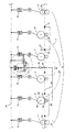
図3は、この他の設計例を示している。ここでは、事実上の基本軸Lが、機械回転軸147から導かれる。このためには、機械回転軸147は、探索が行われ、また発信装置146は、例えばこれにより駆動モジュール130を介して本来の(事実上の)基本軸Lが発信される位置データを送信する。そして、示された機械部分は、あらかじめ接続されている機械と同期的に接続され、その機械の中で、素材ライン144が、例えば機械的な駆動を介して機械カム147により導かれる機械軸105によって、加工される。例えば、取り外しにより生ずる可能性のあるラインの張り具合の変動を調整するためには、引っぱり調整装置143を備えている(例えば引っ張り調整装置を用いた)。付属する調整モジュールは、その際に微調整駆動モジュール107(あるいは一つのオフセット適合)で、それらを介して後位置に接続されている機械(駆動モジュール106と共に)の軸のグループ117の動きをグループ毎に基本軸Lから導かれるものを、パラメーター化する。
FIG. 3 shows another design example. Here, the de facto basic axis L is derived from the
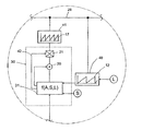
図4は、簡略化された図である、素材ライン2の加工を行うための加工機械1。これは、それぞれに付属する圧力ローラー34を備えた駆動されるいくつものローラー33からなる輪転式印刷機械である。
FIG. 4 is a simplified diagram showing a processing machine 1 for processing the
加工機械1は、基本的には二つのローラー33を備えた搬送軸3により形成される入力搬送ステーションを備えている。別の末端部には(縦方向23を見た場合)同様に二つの相互に作用するローラー33により構成される出力搬送軸4が存在する。搬送軸3と4との間には、4つの加工ステーション5、6、7、8が存在するが、以下には、便宜上簡素化して加工軸5、6、7、8として簡単に示されている。
The processing machine 1 basically includes an input transfer station formed by a transfer shaft 3 having two
軸の概念は、ここでは、付属するローラー33を備えた該当するステーション、またそれに付随するモーターMとそれらに付属する駆動機構9をも備えているものに対して用いられる。この軸の概念は、特にローラー33、34とそれぞれの物理的な回転軸35、36とは、区別しなければならない。
The concept of shaft is used here for the corresponding station with the associated
ここに示された搬送軸3、4と、それと共に作動する加工軸5、6、7、8は、いずいれも一つの付属する単独駆動機構9によって駆動される。これにより、貫かれており、機械シャフト(基本軸)を補う。これに対しては、単独駆動機構9が、相互に同期化されることが必要である。これを行うためには、単独駆動機構9へ、データバス28を介して基本軸信号データが導かれる(下記の記述を参照のこと)ことが必要となる。同期化を行うためには、軸5、6、7、8が、時間的な基本軸関数に従う。この基本軸関数は、データバス28の中に含まれており、これを介して単独駆動機構9へと伝達される。逸脱状況は、見当調整により、まず見当マーク14が(ここでは、該当する縦方向の位置にクロス印でシンボル化されている)、一つの(光学的)センサー29により走査されることにより、補正される。走査から、基本軸関数12に対して修正が見当調整装置30において計算される。これらの補正は、まず単に見当調整装置に従っている軸3、4に影響を与えるのみである。とりあえずその他の加工軸5、6、7、8になんら見当修正が存在しないので(このことは、補足できに実行することができる。以下を参照のこと)、相対的修正の見当修正は、搬送軸3、4と加工軸5、6、7、8との間に該当する。
The conveying shafts 3 and 4 shown here and the
(見当修正の影響を受けない)基本軸Lは、ここでは単に、一つの回路としてシンボル化し示されている。本発明にとって、仮想的な基本軸で、その時の位置が電子的な方法によってのみ作られるものであるか、あるいは、いわゆる実際の基本軸で、その時の位置が、実際に存在する物理的な方法を用いた機械構造を有するシャフトにより、あるいは駆動機構のフィードバックにより示されるものであるかは、さほど重要なことではない。 The basic axis L (not affected by the registration correction) is simply symbolized here as a single circuit. For the present invention, a virtual basic axis whose position is created only by an electronic method or a so-called actual basic axis whose physical position actually exists It is not so important whether it is indicated by a shaft having a mechanical structure using or by feedback of a drive mechanism.
本発明に基づき、グループ15は、見当に従う搬送軸3、4で、上記に詳細説明を行ったような見当修正に応ずるものにより構成されている。見当に従う搬送軸3、4のグループ15に対しては、単に共通の走査が行われるだけである。これは、センサー29により、走査箇所44に対してのみ行われる。またこのセンサーは、例えばフォトダイオード、もしくは1台のCCDカメラである場合もあり、見当マークの認識を行うための回路接続をした判定電子装置を備えている。
In accordance with the present invention, the
共通の走査から、見当に従う搬送軸3、4のグループ15に対して、共通の修正関数16が導かれる。これは、見当マークの走査の程度に基づく期待値と実測値の比較から、位置的な逸脱状況を構成し、またその走査(これは速度である)、若しくはそれにより対応させる関数により構成される。この修正関数は、ここに示された設計例では、期待値S及び/あるいは基本軸関数12の走査結果の比較により示されている。またこれはさらに、-センサー29からの走査信号とともに-計算装置31の中に記憶される。期待値Sは、基本軸関数12及び/あるいは加工軸5、6、7、8に関連して、素材ライン上のどの相対的な位置に、走査箇所44での見当マークが位置するべきなのかという情報を含む。
From the common scan, a
計算装置31の中で(図1bを参照のこと)形成される制御偏差(修正関数16に対応する)から、見当結果-基本軸関数17が導かれる。これは、明確にするために図解説明で示されており、基本軸関数12から逸脱した上昇を誇張し増大したように示している。基本軸関数12は、見当調整12の中に記憶される。修正関数16と基本軸関数12との接続は、同様に本発明に則した見当調整30の中で行われる。コミュニケーション能力に関しては、データバス28が重要であるので、全ての単独駆動機構9では、(変更されていない)基本軸関数12のみならず、修正関数16から形成された見当結果-基本軸17もまた準備されている。その場合、駆動機構9は、変更可能な調整の程度に基づき、あらかじめ設定され、該当する基本軸12/見当結果-基本軸17により制御される。これにより、実質的に、どの軸3、4、5、6、7、8も、設置されている基本軸関数12、17の任意の、(あらかじめの)設定値の程度、あるいは処理/適応に基づく修正関数に基づき、-例えば該当する駆動機構調整装置10において、従うことができる。
From the control deviation (corresponding to the correction function 16) formed in the computing device 31 (see FIG. 1b), the register result-
個々の基本軸関数12、17、あるいは修正関数16は、これを踏まえて駆動機構調整装置10の中で処理され、また個々のモーターMは、その程度に応じて適切な同期化/修正が行われ、パワーエレクトロニクス11を介して駆動される。
Based on this, the individual basic axis functions 12, 17 or the
本発明に基づく見当調整の関数方法は、一部を拡大して、図4bに図解で示している。
一般的に、既に存在する軸の同期化を行うためには、基本軸を備えており、これは、データバス28を介して、単独駆動機構9へ個別に伝達/アドレス化することができる。また、
それぞれの駆動機構9よりも上位に配置され同期化する。一部拡大して示した左側のペー
ジには、見当調整30の詳細を示している。ここでは、期待値Sと走査信号Aとから修正関数16が導き出され、修正の程度に基づき、上位に配置されている基本軸関数12により見当結果-基本軸関数17へと処理される。詳細図から、それぞれの場合、まず期待値S、基本軸関数12、若しくは基本軸L、及び走査信号Aから、計算装置31の中でひとつの関数(A、S、L)が算出されることが解る。ここに提示したケースでは、(優先してその時の/活性化した)基準値が、その値の程度に応じてパラメーター回路を介して、基本軸関数12から見当結果-基本軸関数17が導き出される。詳細図に示したように、見当結果-基本軸関数17の伝達に対して、一つのオフセット加算機20並びに/あるいは一つの変換機構ユニット21が備えられており、計算装置31によりパラメーター回路42を介して応答される。このことは、走査の程度に基づき、純粋な位置ずらし、あるいは伝動装置の導関数、あるいはその双方が、見当結果-基本軸関数17の伝達のために用いられる。修正関数16/見当結果-基本軸関数17の形成のために、走査結果、期待値(これは時間的な期待値関数であり得る)、並びに基本軸12から、位置ずらし19の程度、並びに/あるいは変換機構ユニット21に対しての伝動装置の歯車比が計算され、優先的に関与したTaktrateと調整システムに対して予想される時定数の範囲内で活性化する。パラメーター回路42を介して、これによりこの関数を形成するために必要なパラメーターが、変換機構ユニット20、21に導かれる。
The register adjustment function method according to the present invention is shown partially enlarged and illustrated schematically in FIG. 4b.
In general, in order to synchronize already existing axes, a basic axis is provided, which can be individually transmitted / addressed to the
It is arranged above each
制御偏差がなんら存在せず、あるいは制御を望まない場合は、全てのパラメーターは以下のように測定したり、基準値を示したりすることができる。つまり、歯車20並びに/あるいは21は、差異がなく、また見当結果-基本軸関数17は、基本的には基本軸関数12と同じであるようにする。既に存在する基本軸関数12、17は、それぞれの基本軸ジェネレーター40、41を介して(例えば計算装置の中にあるソフトウエア)データバス28へと該当するアドレス化によりさらに伝達される。アドレス化については、ここで詳細に解説を行わない。アドレス化は、選択的に個々の単独駆動機構9毎に、それぞれのパラメーター、つまり走査箇所44などの付属する軸3、4の間隔の程度に基づき実行される。この点については、以下の記述において詳細に説明を行う。
If there is no control deviation or if control is not desired, all parameters can be measured as follows or reference values can be given. That is, the
補足的に、あるいは代替案として、さらに修正関数16を備えることができる。これは、基本的には、単に基本軸関数12に対する修正を含み、また、-グループ15の軸3、4に対して-直接的に、基本軸関数12の世界的に用いられている同期化周期動作で用いられる修正として、-特に駆動機構9に対して-影響を与える。
In addition or as an alternative, a
さらに搬送軸3、4に対しては、加工軸5、8もまた、グループ43にまとめることができる。これは、独自の、例えば補足的な見当に従った基本軸関数に影響を与える。加工軸5、6、7、8全ては、一つのグループにまとめることができると思われる。ここでは、走査箇所44から最も遠く離れた加工軸5、8が、グループ43にまとめられている。これは、これらに対しては、場合によっては(残-)制御偏差が、上記に記述した理由により特に大きくなるからである。見当に従ったグループ15、43の軸3、4、5、8は、走査を実質的には、中心領域22で、素材ライン2の縦方向23との関係で、つまり実質的に示された軸の中心で実行する。これにより、-上記に記述したように-場合によっては、見当に従う軸の残留する(見当-)逸脱状況が、相互に最小化される。
Furthermore, the processing axes 5 and 8 can also be grouped into the
グループ43の加工軸5、8に対して、計算負荷の観点から簡素化された修正の影響を与える。これらは、製品の長さ26の積25への配分が形成される。前述のケースは、見当マーク14の距離によって一致されている(絶対に必要であるケースではない)。見当調整を用いて、縦方向のエラー27(ここでは誇張して示されている)は、製品の長さ26ごとに算出される。修正を必要とする加工軸5、8ごとに、走査箇所44までの縦方向の間隔45が算出され、加工軸5の修正が、縦方向のエラーと商、つまり縦方向の距離45を製品の長さ26で割ったものとの積から形成される。
The machining axes 5 and 8 of the
最終的に、図5は、様々な基本軸関数12、17、37、並びに修正関数16のダイアグラムを示している。記載されているのは、時間tについての角度のその時の位置である。見当結果-基本軸関数17と見当結果-基本軸関数37は、変更されていない基本軸関数12から導き出される修正-基本軸関数である。見当結果-基本軸37は、基本軸関数12に対する位置ずらし19により構成されているだけである。見当結果-基本軸関数17は、基本軸関数12からの伝動装置の導関数(伝動装置で変速される回転速度に相当)を有している。それにより、見当結果-基本軸関数17は、基本軸関数12とは別の傾斜を有する。またそれにより、基本軸関数12の期間継続38に対して別の期間継続39を有する。見当結果-基本軸関数17のより大きな傾斜を理由に、付属する期間継続39は短い。
Finally, FIG. 5 shows a diagram of the various basic axis functions 12, 17, 37 and the
図2は、このことを踏まえて、修正関数16を示している。これは、基本軸関数12に対して、単に修正を再現しているだけである。この数値で見当に従う軸3、4、5、8が、場合によっては修正される。瞬間位置α角度ではなく、例えば角速度を、該当する基本軸関数/修正関数のための発信信号として用意することができる。
FIG. 2 shows the
1 加工機械
2 素材ライン
3 搬送軸
4 搬送軸
5 加工軸
6 加工軸
7 加工軸
8 加工軸
9 単独駆動機構
10 駆動機構調整
11 パワーエレクトロニクス
12 基本軸関数
13 基本軸の瞬間的位置
14 見当マーク
15 見当に従う軸のグループ
16 修正関数
17 見当結果-基本軸関数
18 記載なし
19 位置ずらし
20 オフセット-加算器
21 変換装置ユニット
22 中央領域
23 素材ラインの縦方向
24 記載なし
25 個々の製品
26 製品の長さ
27 製品の長さ毎の縦方向のエラー
28 データバス
29 センサー
30 見当調整
31 計算装置ユニット
32 記載なし
33 駆動されているローラー
34 加圧ローラー
35 駆動されているローラーの回転軸
36 加圧ローラーの回転軸
37 位置ずらしのみによる見当結果-基本軸関数
38 基本軸関数の周期的継続
39 見当結果-基本軸関数の周期的継続
40 基本軸ジェネレーター
41 基本軸ジェネレーター
42 パラメーター伝送
43 グループ
44 走査箇所
45 走査箇所から加工位置までの距離
S 期待値発信装置
101 駆動機構
102 機械軸、誘導される
103 駆動装置
L 基本軸
F 従属基本軸
105 機械軸
106 従属基本軸を導くための駆動モジュール
107 従属基本軸を導くための微調整駆動装置モジュール
108 従属基本軸を導く前に接続されているオフセット加算器
109 従属基本軸を導いた後に接続されているオフセット加算器
110 機械軸、誘導される
111 機械軸、誘導される
116 補足的な位置ずらし
117 軸のグループ
118 後置されている基本軸
119 事実上の基本軸
120 仮想の基本軸
121 ポジショニングモジュール
122 基本軸サイクル
123 同期化モジュール
124 前に接続されているオフセットモジュール
125 後ろに接続されているオフセットモジュール
126 調整装置モジュール
127 補足的なオフセットモジュール
128 従属誘導サイクル
130 (駆動)装置モジュール
131 駆動-微調整モジュール
132 切り替え装置
133 駆動-オフセットモジュール
134 駆動-オフセット加算器
135 期待値サイクル
136 機械的駆動装置
137 モーター
138 機械
139 基本軸Lから直接的に導かれる機械軸
140 搬送装置
141 巻き出しd装置
142 巻き取り装置)
143 引っぱり調整/ライン記憶装置
144 素材ライン
145 搬送軸
146 発信装置
147 機械カム
DESCRIPTION OF SYMBOLS 1 Processing machine 2 Material line 3 Conveyance axis 4 Conveyance axis 5 Processing axis 6 Processing axis 7 Processing axis 8 Processing axis 9 Single drive mechanism 10 Drive mechanism adjustment 11 Power electronics 12 Basic axis function 13 Instantaneous position of basic axis 14 Registration mark 15 Group of axes according to register 16 Correction function 17 Register result-basic axis function 18 Not described 19 Position shift 20 Offset-adder 21 Converter unit 22 Central area 23 Material line longitudinal direction 24 Not described 25 Individual product 26 Product length 27 Longitudinal error for each product length 28 Data bus 29 Sensor 30 Registration adjustment 31 Computer unit 32 No description 33 Driven roller 34 Pressure roller 35 Rotating shaft of driven roller 36 Pressure roller Rotation axis of 37 Register result only by position shift-basic axis Function 38 Periodic continuation of basic axis function 39 Registration result-Periodic continuation of basic axis function 40 Basic axis generator 41 Basic axis generator 42 Parameter transmission 43 Group 44 Scan location 45 Distance from scan location to machining position S Expected value transmitter DESCRIPTION OF SYMBOLS 101 Drive mechanism 102 Mechanical axis, induced 103 Drive apparatus L Basic axis F Subordinate basic axis 105 Machine axis 106 Drive module for deriving subordinate basic axis 107 Fine adjustment drive module 108 for deriving subordinate basic axis 108 Subordinate basic axis Offset adder connected before leading 109 109 Offset adder connected after guiding the subordinate base axis 110 Machine axis, induced 111 machine axis, induced 116 Supplemental displacement 117 Group of axes 118 Postfix basic axis 119 De facto basic 120 virtual basic axis 121 positioning module 122 basic axis cycle 123 synchronization module 124 offset module connected in front 125 offset module connected in the back 126 regulator module 127 supplementary offset module 128 dependent induction cycle 130 ( Drive) Device module 131 Drive-fine adjustment module 132 Switching device 133 Drive-offset module 134 Drive-offset adder 135 Expected value cycle 136 Mechanical drive device 137 Motor 138 Machine 139 Mechanical axis 140 directly derived from basic axis L 140 Conveying device 141 Unwinding d device 142 Winding device)
143 Pull adjustment /
Claims (9)
すなわち、変換(106、107、108、109)の点から相互に対応している軸の少なくとも一つのグループの全ての軸(102、110、111)は、当該グループについて設定された一つの時間的な従属基本軸関数に従って動くようになっており、この従属基本軸関数は、当該グループの各軸に対しての基本的な軸として設定される従属基本軸Fの瞬間的位置と一致し、適切な変換関数と基本軸関数との結合により形成されるものである。A method for operating a machine (138) having a number of synchronized axes (102, 110, 111, 141, 142, 145), these axes (102, 110, 111, 141, 142, 145) are synchronized with each other by the attached single drive mechanism (103), and according to the temporal basic axis function, which is a function that coincides with the preset instantaneous position (13) of the basic axis L. The movements of the driven and driven shafts (102, 110, 111) are mechanically converted (106, 107, 108, 109), which are respectively predetermined in relation to the basic axis L. According to the corresponding function, it is derived from the basic axis function and is characterized as follows.
That is, convert all of the axes of the at least one group of axes correspond to each other in terms of (106, 107, 108 and 109) (102,110,111), the time of one set for the group This subordinate basic axis function corresponds to the instantaneous position of the subordinate basic axis F set as the basic axis for each axis of the group , and is appropriate. It is formed by the combination of a simple conversion function and a basic axis function.
すなわち、変換関数は、機械的な変換により決定された基本軸の瞬間的位置に対する位相ずらし分である位置ずらしを含む。The method according to claim 1 is characterized as follows.
That is, the conversion function includes a position shift that is a phase shift amount with respect to the instantaneous position of the basic axis determined by mechanical conversion.
すなわち、変換関数は、機械的な変換により決定された基本軸の瞬間的速度に対する回転速度変化を含む。The method according to claim 1 or 2 is characterized as follows.
That is, the conversion function includes a change in rotational speed with respect to the instantaneous speed of the basic axis determined by mechanical conversion.
すなわち、変換関数は、機械的な変換により決定された関数であって、基本軸との関係で伝動装置の歯車比に相当する関数を含む。The method according to any one of claims 1 to 3 is characterized as follows.
That is, the conversion function is a function determined by mechanical conversion, and includes a function corresponding to the gear ratio of the transmission in relation to the basic shaft.
すなわち、機械的な変換に相当するものは、手動によるか、見当調整装置、引っぱり調整装置、ダンサー調整装置のうちのいずれかの調整装置により形成されるかのいずれか一方もしくは両方により与えられる変換関数の微調整を含む。 The method according to any one of claims 1 to 4 is characterized as follows.
That is, the conversion corresponding to the mechanical conversion is a conversion given by one or both of the manual adjustment, the registration adjustment apparatus, the pull adjustment apparatus, and the dancer adjustment apparatus. Includes fine tuning of functions .
すなわち、機械的な変換に相当するものは、手動によるか、見当調整装置、引っぱり調整装置、ダンサー調整装置のうちのいずれかの調整装置により形成されるかのいずれか一方もしくは両方により与えられる変換関数の位置ずらしを含む。 The method according to any one of claims 1 to 5 is characterized as follows.
That is, the conversion corresponding to the mechanical conversion is a conversion given by one or both of the manual adjustment, the registration adjustment apparatus, the pull adjustment apparatus, and the dancer adjustment apparatus. Includes function displacement .
すなわち、機械的な変換に相当するものは、手動によるか、見当調整装置、引っぱり調整装置、ダンサー調整装置のうちのいずれかの調整装置により形成されるかのいずれか一方もしくは両方により与えられる変換関数の回転速度変化を含む。 The method according to any one of claims 1 to 6 is characterized as follows.
That is, the conversion corresponding to the mechanical conversion is a conversion given by one or both of the manual adjustment, the registration adjustment apparatus, the pull adjustment apparatus, and the dancer adjustment apparatus. Includes rotation speed change of function .
すなわち、微調整、位置ずらし、回転速度変化のいずれか一つもしくは二つまたは全てが、基本軸関数の期待値の実行サイクルとの関係で、事実上瞬時に実行される。The method according to any one of claims 5 to 7 is characterized as follows.
That is, any one, two, or all of fine adjustment, position shift, and rotational speed change are executed virtually instantaneously in relation to the execution cycle of the expected value of the basic axis function.
すなわち、補足的な位置ずらしを備えており、これは、単に一つのグループの軸のそれぞれの駆動に対して、従属基本軸に基づき発生する従属基本軸信号の軸への伝達に影響を与えるので、該当する軸は、従属基本軸Fに対してこの位置ずらしの分だけ移動される。The method according to any one of claims 1 to 8 is characterized as follows.
In other words, there is a supplemental displacement, which simply affects the transmission of the dependent basic axis signal generated on the basis of the dependent basic axis to the axis for each drive of a group of axes. The corresponding axis is moved with respect to the dependent basic axis F by this position shift.
Applications Claiming Priority (2)
| Application Number | Priority Date | Filing Date | Title |
|---|---|---|---|
| DE10117455A DE10117455A1 (en) | 2001-04-06 | 2001-04-06 | Process for the synchronized operation of machines with axles driven by individual drives |
| PCT/DE2002/001284 WO2002082192A2 (en) | 2001-04-06 | 2002-04-08 | Method for the synchronised operation of machines having axes actuated by single drives |
Publications (3)
| Publication Number | Publication Date |
|---|---|
| JP2004530207A JP2004530207A (en) | 2004-09-30 |
| JP2004530207A5 JP2004530207A5 (en) | 2009-01-08 |
| JP4292009B2 true JP4292009B2 (en) | 2009-07-08 |
Family
ID=7680809
Family Applications (1)
| Application Number | Title | Priority Date | Filing Date |
|---|---|---|---|
| JP2002580095A Expired - Fee Related JP4292009B2 (en) | 2001-04-06 | 2002-04-08 | Method for synchronized operation of a machine with a shaft driven by a single drive mechanism |
Country Status (9)
| Country | Link |
|---|---|
| US (1) | US6914402B2 (en) |
| EP (1) | EP1373992B1 (en) |
| JP (1) | JP4292009B2 (en) |
| AT (1) | ATE360843T1 (en) |
| AU (1) | AU2002304889A1 (en) |
| DE (2) | DE10117455A1 (en) |
| DK (1) | DK1373992T3 (en) |
| ES (1) | ES2292761T3 (en) |
| WO (1) | WO2002082192A2 (en) |
Families Citing this family (14)
| Publication number | Priority date | Publication date | Assignee | Title |
|---|---|---|---|---|
| JP2005322076A (en) * | 2004-05-10 | 2005-11-17 | Fanuc Ltd | Numerical controller |
| DE102005027435B4 (en) * | 2005-06-14 | 2007-04-26 | Siemens Ag | Control method for a number of position-controlled following axes in a control cycle |
| DE102005040263A1 (en) * | 2005-08-24 | 2007-03-01 | Müller Weingarten AG | Method and device for controlling and regulating the slide movement on servo-electric presses |
| DE102005048472A1 (en) | 2005-10-07 | 2007-04-12 | Bosch Rexroth Ag | Rotary printing machine and method of operating a rotary printing machine |
| US20080143807A1 (en) * | 2006-12-13 | 2008-06-19 | Bartley Russell L | Media printing and folding system |
| DE102007049447B4 (en) | 2007-10-16 | 2023-11-30 | Elau Gmbh | Limit-sensitive electronic cam disk |
| EP2149831B1 (en) | 2008-07-31 | 2012-02-01 | Siemens Aktiengesellschaft | Control method for a composite of several multi-axle handling devices arranged behind or beside each other and data storage medium, control system and composite |
| DE102008053127B4 (en) * | 2008-10-24 | 2015-04-02 | Robert Bosch Gmbh | A provisioning apparatus and method for providing a link signal for controlling a plant |
| DE102009010322A1 (en) * | 2009-02-12 | 2010-08-19 | Harburg-Freudenberger Maschinenbau Gmbh | Method and device for controlling the production of tires |
| DE102010060158B4 (en) * | 2010-10-26 | 2012-07-12 | Schuler Pressen Gmbh | Control device and method for controlling the stations of a production line |
| DE102014001249A1 (en) * | 2014-02-03 | 2015-08-06 | Juan Carlos González-Villar | Drive system for center winder |
| DE102014010336A1 (en) * | 2014-07-10 | 2016-01-28 | Juan Carlos González Villar | Drive system for conveyor, extruder, push, pull, synchronous applications |
| US11338538B2 (en) * | 2016-08-17 | 2022-05-24 | Les Emballages Trium Inc. | Process for manufacturing bags for packaging items, and bag produced therefrom |
| CN108340673B (en) * | 2017-01-23 | 2020-04-10 | 长胜纺织科技发展(上海)有限公司 | Control system for printing equipment and control method thereof |
Family Cites Families (18)
| Publication number | Priority date | Publication date | Assignee | Title |
|---|---|---|---|---|
| DE3234981C3 (en) * | 1982-09-22 | 1998-12-24 | Krauss Maffei Ag | Punching and bending machine for processing wire or tape |
| DE3627719C1 (en) * | 1986-08-14 | 1988-03-03 | Lescha Maschf Gmbh | Excavators, in particular self-propelled hydraulic universal small excavators |
| JP3010583B2 (en) * | 1989-12-31 | 2000-02-21 | 株式会社エスジー | Multi-axis tuning control method |
| DE4214394C2 (en) | 1992-04-30 | 1998-08-20 | Asea Brown Boveri | Drive device for a rotary shaftless rotary printing machine |
| JPH06110553A (en) * | 1992-09-30 | 1994-04-22 | Yokogawa Electric Corp | Positioning controller for motor |
| DE4339628C2 (en) * | 1993-11-20 | 2003-04-10 | Ismar Maschinen Gmbh | kneading |
| DE4420598A1 (en) | 1994-06-13 | 1995-12-14 | Siemens Ag | Numerical positional control of coupled leader and follower shafts |
| US5659480A (en) * | 1995-06-27 | 1997-08-19 | Industrial Service And Machine, Incorporated | Method for coordinating motion control of a multiple axis machine |
| DE19527199C2 (en) | 1995-07-26 | 2002-10-31 | Baumueller Nuernberg Gmbh | Flexographic printing machine and its use |
| DE19626287A1 (en) * | 1996-07-01 | 1997-02-13 | Abb Management Ag | Method for operating a drive system and device for carrying out the method |
| DE19631849C1 (en) * | 1996-08-07 | 1998-01-08 | Svedala Gfa Aufbereitungsmasch | Vibration drive for a screening machine |
| JPH10201279A (en) * | 1997-01-07 | 1998-07-31 | Fanuc Ltd | Motor synchronous rotation control method |
| DE19727507A1 (en) * | 1997-06-30 | 1999-01-07 | Abb Daimler Benz Transp | Regulation for a drive with an asynchronous motor |
| EP0930552A3 (en) | 1998-01-20 | 1999-12-08 | BAUMÜLLER ANLAGEN-SYSTEMTECHNIK GmbH & Co. | Electrical drive system with a virtual, ditributed lead axis |
| ATE257218T1 (en) * | 1998-08-13 | 2004-01-15 | Neg Micon As | CONTROL DEVICE FOR ADJUSTING AND STOPPING THE BLADES OF A WIND TURBINE |
| DE19903869B4 (en) * | 1999-02-01 | 2013-08-14 | Siemens Aktiengesellschaft | Method for controlling the drive of sheet-fed printing machines |
| DE19934044A1 (en) * | 1999-07-16 | 2001-01-25 | Mannesmann Ag | Working clock-synchronous servo axle group coupling/decoupling involves defining axle group demand value with master position value sequence table, servo axle group demand values |
| DE10117454A1 (en) * | 2001-04-06 | 2002-10-17 | Rexroth Indramat Gmbh | Register control procedure |
-
2001
- 2001-04-06 DE DE10117455A patent/DE10117455A1/en not_active Ceased
-
2002
- 2002-04-08 DK DK02732381T patent/DK1373992T3/en active
- 2002-04-08 DE DE50210028T patent/DE50210028D1/en not_active Expired - Lifetime
- 2002-04-08 WO PCT/DE2002/001284 patent/WO2002082192A2/en active IP Right Grant
- 2002-04-08 EP EP02732381A patent/EP1373992B1/en not_active Expired - Lifetime
- 2002-04-08 ES ES02732381T patent/ES2292761T3/en not_active Expired - Lifetime
- 2002-04-08 JP JP2002580095A patent/JP4292009B2/en not_active Expired - Fee Related
- 2002-04-08 US US10/474,100 patent/US6914402B2/en not_active Expired - Lifetime
- 2002-04-08 AU AU2002304889A patent/AU2002304889A1/en not_active Abandoned
- 2002-04-08 AT AT02732381T patent/ATE360843T1/en active
Also Published As
| Publication number | Publication date |
|---|---|
| DE10117455A1 (en) | 2002-11-07 |
| US20040133287A1 (en) | 2004-07-08 |
| DK1373992T3 (en) | 2007-09-17 |
| JP2004530207A (en) | 2004-09-30 |
| US6914402B2 (en) | 2005-07-05 |
| WO2002082192A3 (en) | 2003-04-10 |
| DE50210028D1 (en) | 2007-06-06 |
| AU2002304889A1 (en) | 2002-10-21 |
| ATE360843T1 (en) | 2007-05-15 |
| WO2002082192A2 (en) | 2002-10-17 |
| EP1373992A2 (en) | 2004-01-02 |
| EP1373992B1 (en) | 2007-04-25 |
| ES2292761T3 (en) | 2008-03-16 |
Similar Documents
| Publication | Publication Date | Title |
|---|---|---|
| JP4292009B2 (en) | Method for synchronized operation of a machine with a shaft driven by a single drive mechanism | |
| JP4353547B2 (en) | Method for operating a drive system and apparatus for carrying out this method | |
| CN100434273C (en) | Integrated photoelectronic registration and shaftless transmission control system for intaglio printing machine in a set | |
| JP4359432B2 (en) | How to make register adjustments | |
| CN103676653B (en) | Servo synchronous control method and system applied to gantry mechanism | |
| CN104772978B (en) | Machine set type electronic shaft synchronized mechanical shaft device and controlling method | |
| JPH11511407A (en) | Axisless rotary printing press | |
| CN202592957U (en) | High-speed shaftless transmission printing paper feeding control system | |
| US7012980B2 (en) | Synchronous, clocked communication system with relative clock and method for configuring such a system | |
| JP2013114340A (en) | Motor controller for synchronously controlling master shaft and slave shafts | |
| EP1912325B1 (en) | Electronic line shaft with phased lock loop filtering and predicting | |
| US6925349B2 (en) | Device and method for synchronizing a plurality of electric drive units in a paper processing machine | |
| US7997202B2 (en) | Web offset printing press and method for operating a web offset printing press | |
| CN101716846A (en) | Automatic servo pressure regulating method and device of satellite-type flexible steel roller printing machine | |
| US6354214B1 (en) | Synchronous control system for rotary printing presses | |
| CN102501593B (en) | Material film fixed-length drawing control system suitable for secondary overprinting | |
| US20060207450A1 (en) | Drive device and method for controlling a unit of a printing press | |
| US4406389A (en) | High speed web processing unit adjustable to variable length documents | |
| JP7453268B2 (en) | Multi-axis servo control system | |
| CN108706364A (en) | The improvement device and its control method of GDX2 packing machine inner box paper rolling cuts | |
| JPH1086343A (en) | Method for adjusting register in rotary press and rotary press | |
| US7949009B2 (en) | Method for determining multiturn modulo master axis data | |
| CN104354452A (en) | Embedded shaftless drive system of intaglio printing press | |
| JP2018018131A (en) | Motion control system | |
| CN115104252A (en) | Assembly of an electric motor with an encoder |
Legal Events
| Date | Code | Title | Description |
|---|---|---|---|
| A621 | Written request for application examination |
Free format text: JAPANESE INTERMEDIATE CODE: A621 Effective date: 20050318 |
|
| A131 | Notification of reasons for refusal |
Free format text: JAPANESE INTERMEDIATE CODE: A131 Effective date: 20070828 |
|
| A524 | Written submission of copy of amendment under article 19 pct |
Free format text: JAPANESE INTERMEDIATE CODE: A524 Effective date: 20071128 |
|
| A521 | Request for written amendment filed |
Free format text: JAPANESE INTERMEDIATE CODE: A821 Effective date: 20071129 |
|
| A131 | Notification of reasons for refusal |
Free format text: JAPANESE INTERMEDIATE CODE: A131 Effective date: 20080501 |
|
| A601 | Written request for extension of time |
Free format text: JAPANESE INTERMEDIATE CODE: A601 Effective date: 20080730 |
|
| A602 | Written permission of extension of time |
Free format text: JAPANESE INTERMEDIATE CODE: A602 Effective date: 20080806 |
|
| A601 | Written request for extension of time |
Free format text: JAPANESE INTERMEDIATE CODE: A601 Effective date: 20080829 |
|
| A602 | Written permission of extension of time |
Free format text: JAPANESE INTERMEDIATE CODE: A602 Effective date: 20080905 |
|
| A601 | Written request for extension of time |
Free format text: JAPANESE INTERMEDIATE CODE: A601 Effective date: 20080930 |
|
| A602 | Written permission of extension of time |
Free format text: JAPANESE INTERMEDIATE CODE: A602 Effective date: 20081007 |
|
| A521 | Request for written amendment filed |
Free format text: JAPANESE INTERMEDIATE CODE: A523 Effective date: 20081031 |
|
| A524 | Written submission of copy of amendment under article 19 pct |
Free format text: JAPANESE INTERMEDIATE CODE: A524 Effective date: 20081031 |
|
| A521 | Request for written amendment filed |
Free format text: JAPANESE INTERMEDIATE CODE: A821 Effective date: 20081031 |
|
| TRDD | Decision of grant or rejection written | ||
| A01 | Written decision to grant a patent or to grant a registration (utility model) |
Free format text: JAPANESE INTERMEDIATE CODE: A01 Effective date: 20090317 |
|
| A01 | Written decision to grant a patent or to grant a registration (utility model) |
Free format text: JAPANESE INTERMEDIATE CODE: A01 |
|
| A61 | First payment of annual fees (during grant procedure) |
Free format text: JAPANESE INTERMEDIATE CODE: A61 Effective date: 20090406 |
|
| R150 | Certificate of patent or registration of utility model |
Free format text: JAPANESE INTERMEDIATE CODE: R150 |
|
| FPAY | Renewal fee payment (event date is renewal date of database) |
Free format text: PAYMENT UNTIL: 20120410 Year of fee payment: 3 |
|
| FPAY | Renewal fee payment (event date is renewal date of database) |
Free format text: PAYMENT UNTIL: 20130410 Year of fee payment: 4 |
|
| FPAY | Renewal fee payment (event date is renewal date of database) |
Free format text: PAYMENT UNTIL: 20140410 Year of fee payment: 5 |
|
| R250 | Receipt of annual fees |
Free format text: JAPANESE INTERMEDIATE CODE: R250 |
|
| LAPS | Cancellation because of no payment of annual fees |