JP2005322076A - Numerical controller - Google Patents
Numerical controller Download PDFInfo
- Publication number
- JP2005322076A JP2005322076A JP2004140342A JP2004140342A JP2005322076A JP 2005322076 A JP2005322076 A JP 2005322076A JP 2004140342 A JP2004140342 A JP 2004140342A JP 2004140342 A JP2004140342 A JP 2004140342A JP 2005322076 A JP2005322076 A JP 2005322076A
- Authority
- JP
- Japan
- Prior art keywords
- axis
- slave
- master
- command
- synchronous
- Prior art date
- Legal status (The legal status is an assumption and is not a legal conclusion. Google has not performed a legal analysis and makes no representation as to the accuracy of the status listed.)
- Pending
Links
- 230000001360 synchronised effect Effects 0.000 claims abstract description 31
- 230000001133 acceleration Effects 0.000 description 24
- 238000000034 method Methods 0.000 description 20
- 238000003754 machining Methods 0.000 description 5
- 238000010586 diagram Methods 0.000 description 3
- 238000009825 accumulation Methods 0.000 description 2
- 239000004973 liquid crystal related substance Substances 0.000 description 1
Images


Classifications
-
- G—PHYSICS
- G05—CONTROLLING; REGULATING
- G05B—CONTROL OR REGULATING SYSTEMS IN GENERAL; FUNCTIONAL ELEMENTS OF SUCH SYSTEMS; MONITORING OR TESTING ARRANGEMENTS FOR SUCH SYSTEMS OR ELEMENTS
- G05B19/00—Programme-control systems
- G05B19/02—Programme-control systems electric
- G05B19/18—Numerical control [NC], i.e. automatically operating machines, in particular machine tools, e.g. in a manufacturing environment, so as to execute positioning, movement or co-ordinated operations by means of programme data in numerical form
- G05B19/414—Structure of the control system, e.g. common controller or multiprocessor systems, interface to servo, programmable interface controller
-
- G—PHYSICS
- G05—CONTROLLING; REGULATING
- G05B—CONTROL OR REGULATING SYSTEMS IN GENERAL; FUNCTIONAL ELEMENTS OF SUCH SYSTEMS; MONITORING OR TESTING ARRANGEMENTS FOR SUCH SYSTEMS OR ELEMENTS
- G05B19/00—Programme-control systems
- G05B19/02—Programme-control systems electric
- G05B19/18—Numerical control [NC], i.e. automatically operating machines, in particular machine tools, e.g. in a manufacturing environment, so as to execute positioning, movement or co-ordinated operations by means of programme data in numerical form
- G05B19/182—Numerical control [NC], i.e. automatically operating machines, in particular machine tools, e.g. in a manufacturing environment, so as to execute positioning, movement or co-ordinated operations by means of programme data in numerical form characterised by the machine tool function, e.g. thread cutting, cam making, tool direction control
- G05B19/186—Generation of screw- or gearlike surfaces
-
- G—PHYSICS
- G05—CONTROLLING; REGULATING
- G05B—CONTROL OR REGULATING SYSTEMS IN GENERAL; FUNCTIONAL ELEMENTS OF SUCH SYSTEMS; MONITORING OR TESTING ARRANGEMENTS FOR SUCH SYSTEMS OR ELEMENTS
- G05B2219/00—Program-control systems
- G05B2219/30—Nc systems
- G05B2219/42—Servomotor, servo controller kind till VSS
- G05B2219/42186—Master slave, motion proportional to axis
-
- G—PHYSICS
- G05—CONTROLLING; REGULATING
- G05B—CONTROL OR REGULATING SYSTEMS IN GENERAL; FUNCTIONAL ELEMENTS OF SUCH SYSTEMS; MONITORING OR TESTING ARRANGEMENTS FOR SUCH SYSTEMS OR ELEMENTS
- G05B2219/00—Program-control systems
- G05B2219/30—Nc systems
- G05B2219/50—Machine tool, machine tool null till machine tool work handling
- G05B2219/50218—Synchronize groups of axis, spindles
Abstract
Description
本発明は、複数の制御系統を備え、系統を跨いだ軸をも同期制御が可能な数値制御装置に関する。 The present invention relates to a numerical control apparatus including a plurality of control systems and capable of synchronously controlling an axis extending over the systems.
複数の制御系統を備え、各制御系統毎にそれぞれの各軸を駆動制御する数値制御装置はすでに公知である。さらに、異なる制御系統の軸を同期制御できるようにした数値制御装置も公知である。通常、この同期制御は、一方の軸(マスタ軸)への移動指令を、同期させる他方の軸(スレーブ軸)への移動指令に加算してこの他方の軸(スレーブ軸)への最終的な移動指令とする重畳制御がなされている。 A numerical controller that includes a plurality of control systems and drives and controls each axis for each control system is already known. Furthermore, a numerical control device that enables synchronous control of axes of different control systems is also known. Normally, this synchronous control adds the movement command to one axis (master axis) to the movement command to the other axis (slave axis) to be synchronized, and finally moves to the other axis (slave axis). Superimposition control as a movement command is performed.
上述した従来の同期制御は、マスタ軸に対してスレーブ軸を1対1に同期させるものである。マスタ軸の移動指令をスレーブ軸への移動指令に加算することによって、スレーブ軸をマスタ軸と共に移動させ、かつ、マスタ軸に対してスレーブ軸を相対的に移動させることによって、移動しているマスタ軸に対して同期してスレーブ軸を相対移動させるものである。一方の軸に対して所定比率で他方の軸を同期させることはできない。 In the conventional synchronization control described above, the slave axis is synchronized with the master axis on a one-to-one basis. By adding the movement command for the master axis to the movement command for the slave axis, the slave axis is moved together with the master axis, and the slave axis is moved relative to the master axis, thereby moving the master The slave axis is moved relative to the axis in synchronization. It is not possible to synchronize the other axis at a predetermined ratio with respect to one axis.
一方、歯車加工等においては、ワークを回転させる一方の軸に対して、工具を回転させる軸を所定比率で回転させることによって、ワークに対して歯車加工を行うものであるが、従来の数値制御装置では、このような一方の軸に対して他方の軸を所定比率で回転するように同期制御することができない。又、同期制御する際に所定位相関係をもって同期制御することもできない。 On the other hand, in gear machining and the like, gear machining is performed on a workpiece by rotating a shaft that rotates a tool at a predetermined ratio with respect to one shaft that rotates a workpiece. The apparatus cannot perform synchronous control so that the other shaft rotates at a predetermined ratio with respect to such one shaft. Further, when performing synchronous control, synchronous control cannot be performed with a predetermined phase relationship.
そこで、本発明の目的は、系統の異なる軸間を所望の比率で同期制御ができる数値制御装置を提供することにある。さらには、所望の位相関係をもって同期制御が可能な数値制御装置を提供することにある。 Therefore, an object of the present invention is to provide a numerical control device capable of synchronously controlling between different axes of a system at a desired ratio. It is another object of the present invention to provide a numerical controller capable of synchronous control with a desired phase relationship.
本発明は、複数の制御系統を持つ数値制御装置において、各系統間の軸の同期関係を設定する手段と、設定された同期マスタ軸の移動指令に設定倍率をかけて同期移動量を生成する同期移動量生成手段と、設定されたスレーブ軸の移動指令に前記同期移動量を加算しスレーブ軸への移動指令とするスレーブ軸同期指令手段とを備えることによって、スレーブ軸をマスタ軸に対して設定倍率で同期させて駆動制御できるようにした。
また、マスタ軸とスレーブ軸の位相合わせ位置を設定する手段と、該設定されたマスタ軸とスレーブ軸の位相合わせ位置が合うようにスレーブ軸への移動指令を補正する手段を設けて、マスタ軸とスレーブ軸の位相関係をも設定し、駆動制御できるようにした。
The present invention, in a numerical control apparatus having a plurality of control systems, generates a synchronous movement amount by multiplying a set magnification by a means for setting a synchronous relationship of axes between each system and a movement command of the set synchronous master axis By providing synchronous movement amount generation means and slave axis synchronization command means for adding the synchronous movement amount to the set slave axis movement command and using it as a movement command to the slave axis, the slave axis with respect to the master axis The drive can be controlled in synchronization with the set magnification.
In addition, there is provided means for setting the phase alignment position of the master axis and the slave axis, and means for correcting a movement command to the slave axis so that the phase alignment position of the set master axis and the slave axis matches. The phase relationship between the slave axis and the slave axis can also be set to control the drive.
本発明は、設定された所望の比率でマスタ軸とスレーブ軸を同期制御することができる。さらに、マスタ軸に対してスレーブ軸を、設定位相関係をもって同期制御させることができる。 According to the present invention, the master axis and the slave axis can be synchronously controlled at a set desired ratio. Furthermore, the slave axis can be synchronously controlled with the set phase relationship with respect to the master axis.
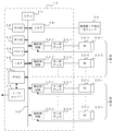
図1は本発明の一実施形態の数値制御装置10の要部ブロック図である。CPU11は数値制御装置10を全体的に制御するプロセッサである。CPU11には、バス19を介して、ROM12、RAM13、CMOS14、インターフェイス15,18、PMC(プログラマブル・マシン・コントローラ)16、軸制御回路30-1〜30-nが接続されている。CPU11は、ROM12に格納されたシステムプログラムを、バス19を介して読み出し、該システムプログラムに従って数値制御装置全体を制御する。RAM13には一時的な計算データや表示データ及び表示器/手動入力ユニット20を介してオペレータが入力した各種データが格納される。インタフェース18を介してバス19に接続される表示器/手動入力ユニット20は、CRTや液晶等で構成される表示器とキーボート等で構成される手動入力手段とからなる。
CMOSメモリ14は図示しないバッテリでバックアップされ、数値制御装置10の電源がオフされても記憶状態が保持される不揮発性メモリとして構成される。CMOSメモリ14中には、インターフェイス15を介して読み込まれた加工プログラムや表示器/手動入力ユニット20を介して入力された加工プログラム等が記憶される。
FIG. 1 is a principal block diagram of a
The CMOS memory 14 is configured as a non-volatile memory that is backed up by a battery (not shown) and that retains the storage state even when the power of the
インターフェイス15は、数値制御装置10と外部機器との接続を可能とするものである。PMC16は、数値制御装置10に内蔵されたシーケンスプログラムで制御対象物の工作機械の補助装置にI/Oユニット17を介して信号を出力し制御する。また、数値制御装置で制御される制御対象物である工作機械の本体に配備された操作盤の各種スイッチ等の信号を受け、必要な信号処理をした後、CPU11に渡す。
各軸の軸制御回路30-1〜30-nには、それぞれサーボアンプ31-1〜31-nが接続され、該サーボアンプ31-1〜31-nには、それぞれのサーボモータ32-1〜32-nが接続されている。又、各サーボモータ32-1〜32-nには位置・速度検出器33-1〜33-nが取り付けられており、該位置・速度検出器33-1〜33-nの出力はそれぞれの軸制御回路30-1〜30-nにフィードバックされている。
The interface 15 enables connection between the
Servo amplifiers 31-1 to 31-n are connected to the axis control circuits 30-1 to 30-n of the respective axes, and the servo motors 32-1 are connected to the servo amplifiers 31-1 to 31-n. ~ 32-n are connected. Further, position / speed detectors 33-1 to 33-n are attached to the servo motors 32-1 to 32-n, and the outputs of the position / speed detectors 33-1 to 33-n are respectively It is fed back to the axis control circuits 30-1 to 30-n.
各軸の軸制御回路30-1〜30-nはCPU11からの各軸の移動指令と位置・速度検出器からの位置、速度フィードバック信号に基づいて、位置、速度のフィードバック制御を行い、さらに、電流ループ制御をも行ってサーボアンプ31-1〜31-nを介して各軸サーボモータ32-1〜32-nを駆動制御する。
The axis control circuits 30-1 to 30-n for each axis perform position and speed feedback control based on the movement command of each axis from the
本実施形態の数値制御装置10は複数の系統を制御できるものであり、図1に示した実施形態の数値制御装置は、2つの制御系統を制御できるものとし、サーボモータ32-1〜32-(i-1)は、制御系統1の各軸を駆動するサーボモータであり、サーボモータ32-i〜32-nは、制御系統2の各軸を駆動するサーボモータである。
The
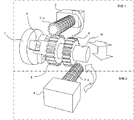
図2は、この数値制御装置10を用いた歯車加工の例の説明図である。
ワークWをチャック2によってマスタ軸1に取り付け、該ワークWを回転工具3a,4aにより歯車加工を行うものである。回転工具3a,4aを回転させる軸がスレーブ軸3、4となり、このマスタ軸1とスレーブ軸3、4を同期制御して歯車5,6を加工するものである。この図2で示す例では、マスタ軸1と回転工具3aのスレーブ軸3が制御系統1に属し、スレーブ軸4が制御系統2に属するものとしている。
FIG. 2 is an explanatory diagram of an example of gear machining using the
The workpiece W is attached to the
この歯車加工を行う場合、マスタ軸1に回転に対して所定比率の回転速度で同期してスレーブ軸3,4を回転させて回転工具3a,4aを回転させて加工を行う必要がある。さらに、繰り返し歯車の溝加工を行うことから、マスタ軸1とスレーブ軸3,4の位相を合わせる必要がある。
以上のような、マスタ軸に対してスレーブ軸を所定同期比率で駆動し、かつ、位相を合わせることが必要な加工に対して本実施形態の数値制御装置10を適用するものである。
When this gear processing is performed, it is necessary to rotate the
The
図3、図4は、本実施形態における同期制御を中心とした数値制御装置10のCPU11が実施する処理のフローチャートである。CPU11は、CMOSメモリ14に制御系統毎に設定格納されている加工プログラムに基づいて、制御系統毎に並行して図3,図4に示す処理を実行する。
3 and 4 are flowcharts of processing executed by the
まず、マスタ軸、スレーブ軸、スレーブ軸と同期開始させるマスタ軸の位相合わせ位置、同期比をパラメータ設定しておく。そして、加工指令を表示器/手動入力ユニット20から入力すると、CPU11は制御系統毎に並行して図3,図4に示す処理を開始する。まず、位相合わせ量を「0」とし、当該系統の系統待ち合わせカウンタを「0」にセットする(ステップS1,S2)。次に、加工プログラムを1ブロックを読み出して解析し、該ブロックの指令が同期指令か、同期解除指令か、位相合わせ指令か、移動指令か判別し(ステップS4,S6,S8,S10)、これらの指令でなければ、従来と同様に、解析したブロックの指令を実行して(ステップS11)、ステップS14に移行する。又、移動指令であると、該指令に基づいて補間分配処理を行い各軸移動指令を生成し(ステップS12)、各軸の指令位置を記憶するレジスタに各軸への分配移動指令を加算して各軸位置(指令位置)を求め(ステップS13)、ステップS14に移行する。
First, parameters are set for the phase alignment position and synchronization ratio of the master axis to be synchronized with the master axis, slave axis, and slave axis. When a processing command is input from the display /
ステップS14では、補間後の加減速処理を実行し、加減速処理後の各軸移動指令を生成すると共に、該加減速処理での溜まり量を生成する。例えば、加減速方式が直線型加減速方式の場合には、加減速処理のためのレジスタに格納されている各移動指令を加算し溜まり量を求める。次に、同期処理中を示すフラグF1が「1」か判別し、「1」でなければ(最初は初期設定で「0」である。)、ステップS32に移行して、ステップS14で求めた加減速処理後の各軸移動指令を各軸の軸制御回路30-1〜30-(i-1)又は30-i〜30-nに出力し、ステップS3に移行する。
以下、同期指令が加工プログラムから読み出されない限り、ステップS3,S4,S6,S8,S10,S12,S13(又はS11)及びステップS14,S15,S32の処理を繰り返し実行し、各系統をそれぞれ独立して駆動制御する。
In step S14, acceleration / deceleration processing after interpolation is executed to generate each axis movement command after acceleration / deceleration processing, and a pool amount in the acceleration / deceleration processing is generated. For example, when the acceleration / deceleration method is a linear acceleration / deceleration method, each movement command stored in a register for acceleration / deceleration processing is added to obtain the accumulated amount. Next, it is determined whether the flag F1 indicating that synchronization processing is in progress is “1”. If the flag F1 is not “1” (initially “0” by default), the process proceeds to step S32 and obtained in step S14. Each axis movement command after acceleration / deceleration processing is output to the axis control circuits 30-1 to 30- (i-1) or 30-i to 30-n of each axis, and the process proceeds to step S3.
Hereinafter, unless the synchronization command is read from the machining program, the processes of steps S3, S4, S6, S8, S10, S12, S13 (or S11) and steps S14, S15, and S32 are repeatedly executed, and each system is made independent. Drive control.
一方、読み出したブロックの指令が同期指令であると(ステップS4)、フラグF1,F3を「1」にセットし(ステップS5)、ステップS14の補間後の加減速処理を行った後、ステップS15でフラグF1が「1」か判断し、この場合「1」と判断されるから、ステップS16に移行して、当該系統の系統待ち合わせカウンタを「1」インクリメントする。そして全系統の系統待ち合わせカウンタの値が同じになるまで待つ(ステップS17)。 On the other hand, if the command of the read block is a synchronization command (step S4), the flags F1 and F3 are set to “1” (step S5), the acceleration / deceleration process after the interpolation in step S14 is performed, and then step S15. Thus, it is determined whether the flag F1 is "1". In this case, it is determined that the flag F1 is "1". Therefore, the process proceeds to step S16, and the system waiting counter of the system is incremented by "1". And it waits until the value of the system waiting counter of all systems becomes the same (step S17).
全系統待ち合わせカウンタの値が同じ値となると、当該系統が設定されたマスタ軸を有する系統か判断し(ステップS18)、マスタ軸を有する系統であれば、ステップS14で求めたマスタ軸に対する補間後の移動指令に同期比を乗じてスレーブ軸の移動量に換算した同期移動量を求め(ステップS19)、該同期移動量にレジスタに記憶する位相合わせ量を加算して位相合わせ量(なお、この位相合わせ量は初期設定で最初は「0」である)を加算した同期移動量としてレジスタに記憶する。そして、位相合わせ量を「0」にリセットし(ステップS20)、ステップS21に移行する。又、ステップS18で当該系統がマスタ軸を有する系統ではないと判断されたときには、ステップS19,S20処理を行わず、ステップS21に移行する。
ステップS21では、待ち合わせカウンタを「1」インクリメントし、全系統の系統待ち合わせカウンタの値が同一の値になるまで待つ(ステップS22)。全系統の系統待ち合わせカウンタの値が同じとなると、当該系統にスレーブ軸を有するか判断し(ステップS23)、有していなければステップS32に移行する。又、スレーブ軸を有していれば、フラグF3が「1」か判断し(ステップS24)、「1」ならばステップS13で求めたスレーブ軸の位置をスレーブ軸位相合わせ位置としてレジスタに格納し(ステップS25)、フラグF3を「0」にリセットする(ステップS26)。なお、ステップS24でフラグF3が「1」でなければ、ステップS25,S26の処理は実行しない。すなわち、同期指令がなされ、フラグF3が「1」にセットされた時点でのみ、そのときのスレーブ軸位置をスレーブ軸位相合わせ位置として記憶するものである。
When the values of all the system queuing counters are the same, it is determined whether the system has a set master axis (step S18). If the system has a master axis, after interpolation for the master axis obtained in step S14. Is obtained by multiplying the movement command by the synchronization ratio and converting it to the movement amount of the slave axis (step S19), and adding the phase adjustment amount stored in the register to the synchronization movement amount The phase adjustment amount is initially set and is initially “0”), and is stored in the register as a synchronous movement amount obtained by adding. Then, the phase alignment amount is reset to “0” (step S20), and the process proceeds to step S21. When it is determined in step S18 that the system is not a system having a master axis, the process proceeds to step S21 without performing steps S19 and S20.
In step S21, the waiting counter is incremented by "1" and waits until the values of the system waiting counters of all systems become the same value (step S22). If the values of the system queuing counters of all systems are the same, it is determined whether the system has a slave axis (step S23), and if not, the process proceeds to step S32. If it has a slave axis, it is determined whether the flag F3 is “1” (step S24). If it is “1”, the slave axis position obtained in step S13 is stored in the register as the slave axis phase alignment position. (Step S25), the flag F3 is reset to “0” (Step S26). If the flag F3 is not “1” in step S24, the processes in steps S25 and S26 are not executed. That is, only when the synchronization command is issued and the flag F3 is set to “1”, the slave axis position at that time is stored as the slave axis phase alignment position.
次に、ステップS14で求めた加減速処理後の移動指令にステップS20で求めた同期移動量を加算して、同期移動量を補正した、スレーブ軸に対する加減速処理後の移動指令を求める(ステップS27)。そして、ステップS13で求めたスレーブ軸の位置に同期移動量を加算してスレーブ軸位置を求め記憶する(ステップS28)。 Next, the movement command after acceleration / deceleration processing for the slave axis is obtained by adding the synchronous movement amount obtained at step S20 to the movement command after acceleration / deceleration processing obtained at step S14 (step S20). S27). Then, the slave axis position is obtained and stored by adding the synchronous movement amount to the slave axis position obtained in step S13 (step S28).
次にフラグF2が「1」か判断し、「1」でなければ、ステップS32に移行して、各軸加減速処理後の移動指令を各軸制御回路各軸の軸制御回路30-1〜30-(i-1)又は30-i〜30-nに出力する。スレーブ軸以外の各軸に対しては、ステップS14で求めた加減速後の移動指令が出力され、スレーブ軸に対しては、ステップS27で求めた加減速後の移動指令が出力されることになる。 Next, it is determined whether or not the flag F2 is “1”. If it is not “1”, the process proceeds to step S32, and the movement command after each axis acceleration / deceleration processing is sent to the axis control circuit 30-1 to each axis control circuit. Output to 30- (i-1) or 30-i to 30-n. The acceleration / deceleration movement command obtained in step S14 is output to each axis other than the slave axis, and the acceleration / deceleration movement command obtained in step S27 is output to the slave axis. Become.
以下、同期指令が出力された後、位相合わせ指令が出力されるまでの間は、ステップS3,S4,S6,S8,S10、S12,S13(又はS11),S14〜S24,S27〜S29,S32の処理を繰り返し実行することになり、スレーブ軸には、当該スレーブ軸の加減速処理後の移動指令に同期移動量(マスタ軸の加減速処理後の移動指令に同期比をかけて得られた移動量)が加算されて移動指令として出力されることになり、マスタ軸に対してスレーブ軸は、設定された同期比で、同期して駆動されることになる。 Hereinafter, after the synchronization command is output and until the phase alignment command is output, steps S3, S4, S6, S8, S10, S12, S13 (or S11), S14 to S24, S27 to S29, and S32 are performed. The slave axis is obtained by multiplying the movement command after the acceleration / deceleration processing of the slave axis by the synchronous movement amount (the synchronization command is applied to the movement command after the acceleration / deceleration processing of the master axis). (Movement amount) is added and output as a movement command, and the slave axis is driven in synchronism with the set synchronization ratio with respect to the master axis.
そして、加工プログラムより位相合わせ指令が読み込まれると(ステップS8)、ステップS9でフラグF2が「1」にセットされる。ステップS9でフラグF2が「1」にセットされた後、ステップS14からステップS29までの処理がなされ、該ステップS29で、フラグF2が「1」であることが判別されるので、ステップS30で位相合わせ量を求める。この位相合わせ量は、ステップS13で求めたマスタ軸の位置(指令位置)からステップS14で求めたマスタ軸の加減速処理での溜まり量を減じて、マスタ軸の実際の位置(軸制御回路に指令した位置)を求め、このマスタ軸の実際の位置から設定されているマスタ軸位相合わせ位置を減じて、マスタ軸の実際の位置と設定マスタ軸位相合わせ位置との差を求め、この差に同期比を乗じて、スレーブ軸の移動量に換算した差を求める。さらに、ステップS13で求めたスレーブ軸の位置からスレーブ軸の加減速処理での溜まり量を減じて、スレーブ軸の実際の位置を求め、このスレーブ軸の実際の位置から、ステップS25で求めたスレーブ軸位相合わせ位置を減じてスレーブ軸における実際の位置とスレーブ軸位相合わせ位置との差を求め、この差をマスタ軸の前記差から減じて、マスタ軸とスレーブ軸の位相合わせ位置からのずれ量の差を位相合わせ量として求める(ステップS30)。そしてフラグF2を「0」にリセットし(ステップS31)、スレーブ軸はステップS27で求めた移動指令を他の軸はステップS14で求めた加減速処理後の移動指令を出力する(ステップS32)。 When a phase matching command is read from the machining program (step S8), the flag F2 is set to “1” in step S9. After the flag F2 is set to “1” in step S9, the processing from step S14 to step S29 is performed. In step S29, it is determined that the flag F2 is “1”. Find the combined amount. This phase alignment amount is obtained by subtracting the amount of accumulation in the acceleration / deceleration processing of the master axis obtained in step S14 from the position (command position) of the master axis obtained in step S13 to obtain the actual position of the master axis (in the axis control circuit). Commanded position), subtract the set master axis phase alignment position from the actual master axis position to determine the difference between the actual master axis position and the set master axis phase alignment position. Multiply by the synchronization ratio to find the difference converted to the slave axis travel. Further, the actual position of the slave axis is obtained by subtracting the accumulated amount in the acceleration / deceleration processing of the slave axis from the position of the slave axis obtained in step S13, and the slave position obtained in step S25 is obtained from the actual position of the slave axis. The axis phase alignment position is subtracted to obtain the difference between the actual position on the slave axis and the slave axis phase alignment position, and this difference is subtracted from the difference between the master axis and the deviation from the phase alignment position of the master axis and slave axis. Is obtained as a phase matching amount (step S30). Then, the flag F2 is reset to “0” (step S31), and the slave axis outputs the movement command obtained in step S27, and the other axes output the movement command after acceleration / deceleration processing obtained in step S14 (step S32).
次の周期では、ステップS19,S20でマスタ軸の加減速処理後の移動指令をスレーブ軸の移動量に換算した移動指令にステップS30で求めた位相合わせ量を加算し、同期移動量を求めて、ステップS27で、スレーブ軸の加減速処理後の移動指令に加算されることになるから、スレーブ軸に対しては、マスタ軸の移動指令に対応する分及び、位相合わせ量分が加算されることになる。スレーブ軸に位相合わせ量が加算されるから、マスタ軸とスレーブ軸の位相合わせ位置からのずれ量が「0」となり、位相が合致することになる。よって、マスタ軸とスレーブ軸は設定同期比率で同期しかつ位相合わせがなされた状態で駆動されることになる。 In the next cycle, the phase adjustment amount obtained in step S30 is added to the movement command obtained by converting the movement command after the acceleration / deceleration processing of the master axis in steps S19 and S20 into the movement amount of the slave axis to obtain the synchronous movement amount. In step S27, the value is added to the movement command after the acceleration / deceleration processing of the slave axis. Therefore, the amount corresponding to the movement command of the master axis and the amount of phase alignment are added to the slave axis. It will be. Since the phase alignment amount is added to the slave axis, the deviation amount from the phase alignment position of the master axis and the slave axis becomes “0”, and the phases match. Therefore, the master axis and the slave axis are driven in a state where they are synchronized at the set synchronization ratio and phase-matched.
そして次の周期からは、ステップS20で位相合わせ量が「0」にセットされていることから、スレーブ軸は、マスタ軸の移動指令が重畳されるだけとなり、設定同期比率で駆動されることになる。 From the next cycle, since the phase alignment amount is set to “0” in step S20, the slave axis is only driven with the master axis movement command and driven at the set synchronization ratio. Become.
そして、加工プログラムから同期解除指令が読み込まれるとステップS6からステップS7に移行してフラグF1が「0」にリセットされることから、以後は、ステップS3,S4,S6,S8,S10,S12,S13(又はS11)及びステップS14,S15,S32の処理を繰り返し実行し、各系統をそれぞれ独立して駆動制御する。 Then, when a synchronization cancellation command is read from the machining program, the process proceeds from step S6 to step S7 and the flag F1 is reset to “0”. Henceforth, steps S3, S4, S6, S8, S10, S12, The processes of S13 (or S11) and steps S14, S15, and S32 are repeatedly executed, and each system is independently driven and controlled.
上述した実施形態では、補間後に加減速処理を行う場合について、説明した。補間前加減速処理を行う場合は、各軸への移動指令は、加減速された後の移動指令であるから、加減速処理の溜まり量を考慮する必要がなく、各軸への移動指令が、そのまま実際の移動指令となり、位置も溜まり量を考慮する必要なく指令位置が実際の位置となる。 In the above-described embodiment, the case where acceleration / deceleration processing is performed after interpolation has been described. When performing pre-interpolation acceleration / deceleration processing, the movement command to each axis is the movement command after acceleration / deceleration, so there is no need to consider the accumulated amount of acceleration / deceleration processing. The actual movement command is used as it is, and the command position becomes the actual position without considering the amount of accumulation.
上述した実施形態では、マスタ軸とスレーブ軸の位相合わせ位置について、マスタ軸の位相合わせ位置はパラメータで設定し、スレーブ軸の位相合わせ位置は同期開始時のスレーブ軸の位置(ステップS25)とした。スレーブ軸の位相合わせ位置もパラメータにより設定してもよい。 In the embodiment described above, for the phase alignment position of the master axis and slave axis, the phase alignment position of the master axis is set as a parameter, and the phase alignment position of the slave axis is the position of the slave axis at the start of synchronization (step S25). . The phase alignment position of the slave axis may also be set by parameters.
1 マスタ軸
2 チャック
3、4 スレーブ軸
3a、4a 回転工具
5、6 歯車
W ワーク
1
Claims (2)
各系統間の軸の同期関係を設定する手段と、
設定された同期マスタ軸の移動指令に設定倍率をかけて同期移動量を生成する同期移動量生成手段と、
設定されたスレーブ軸の移動指令に前記同期移動量を加算しスレーブ軸への移動指令とするスレーブ軸同期指令手段と、
を備えることを特徴とする数値制御装置。 In a numerical control device having a plurality of control systems,
Means for setting the axis synchronization relationship between each system;
A synchronous movement amount generating means for generating a synchronous movement amount by multiplying a set synchronous master axis movement command by a set magnification;
Slave axis synchronization command means for adding a movement amount to the slave axis by adding the synchronous movement amount to the set slave axis movement command;
A numerical control device comprising:
The means for setting a phase alignment position of a master axis and a slave axis, and means for correcting a movement command to the slave axis so that the set phase alignment positions of the master axis and the slave axis are matched. Numerical control unit.
Priority Applications (5)
| Application Number | Priority Date | Filing Date | Title |
|---|---|---|---|
| JP2004140342A JP2005322076A (en) | 2004-05-10 | 2004-05-10 | Numerical controller |
| US11/123,132 US20050248304A1 (en) | 2004-05-10 | 2005-05-06 | Numerical controller |
| EP05252834A EP1596264B1 (en) | 2004-05-10 | 2005-05-09 | Numerical controller |
| DE602005005106T DE602005005106T2 (en) | 2004-05-10 | 2005-05-09 | Numerical control |
| CN200510069089.8A CN1696852A (en) | 2004-05-10 | 2005-05-10 | Numerical controller |
Applications Claiming Priority (1)
| Application Number | Priority Date | Filing Date | Title |
|---|---|---|---|
| JP2004140342A JP2005322076A (en) | 2004-05-10 | 2004-05-10 | Numerical controller |
Publications (1)
| Publication Number | Publication Date |
|---|---|
| JP2005322076A true JP2005322076A (en) | 2005-11-17 |
Family
ID=34941205
Family Applications (1)
| Application Number | Title | Priority Date | Filing Date |
|---|---|---|---|
| JP2004140342A Pending JP2005322076A (en) | 2004-05-10 | 2004-05-10 | Numerical controller |
Country Status (5)
| Country | Link |
|---|---|
| US (1) | US20050248304A1 (en) |
| EP (1) | EP1596264B1 (en) |
| JP (1) | JP2005322076A (en) |
| CN (1) | CN1696852A (en) |
| DE (1) | DE602005005106T2 (en) |
Cited By (2)
| Publication number | Priority date | Publication date | Assignee | Title |
|---|---|---|---|---|
| DE102012022522A1 (en) | 2011-11-25 | 2013-05-29 | Fanuc Corporation | A motor controller for synchronously controlling a commander axis and a command receiver axis |
| DE112021002502T5 (en) | 2020-04-24 | 2023-02-23 | Fanuc Corporation | STEERING |
Families Citing this family (8)
| Publication number | Priority date | Publication date | Assignee | Title |
|---|---|---|---|---|
| CN102306011B (en) * | 2011-05-17 | 2016-04-06 | 机械科学研究总院先进制造技术研究中心 | A kind of Double-axis synchronous control method for linear motion unit |
| JP5215446B2 (en) * | 2011-11-02 | 2013-06-19 | ファナック株式会社 | Gear machine control device |
| JP6333782B2 (en) * | 2015-08-03 | 2018-05-30 | ファナック株式会社 | Synchronous control device having function of eliminating shock of synchronous start block |
| JP6063013B1 (en) * | 2015-08-27 | 2017-01-18 | ファナック株式会社 | Numerical control device with machining condition adjustment function to suppress chatter or tool wear / breakage |
| JP6441257B2 (en) * | 2016-04-28 | 2018-12-19 | ファナック株式会社 | Numerical control apparatus and synchronous tracking control method |
| CN107728579B (en) * | 2017-11-07 | 2020-05-08 | 新代科技(苏州)有限公司 | Main shaft cooperative numerical control system and method for different forms |
| CN112327759B (en) * | 2020-10-21 | 2021-12-28 | 苏州谷夫道自动化科技有限公司 | Method and system for synchronizing channels of multi-channel numerical control system |
| CN112305997B (en) * | 2020-11-02 | 2021-12-03 | 苏州浩智工业控制技术有限公司 | Multi-process based control method and system of multi-channel numerical control system |
Family Cites Families (10)
| Publication number | Priority date | Publication date | Assignee | Title |
|---|---|---|---|---|
| FR2617349B1 (en) * | 1987-06-26 | 1989-10-20 | Thomson Csf | METHOD AND DEVICE FOR DIGITAL SYNTHESIS OF A CLOCK SIGNAL |
| EP0385459A3 (en) * | 1989-03-02 | 1990-11-14 | Toyoda Koki Kabushiki Kaisha | Synchronizing control apparatus |
| JP2518457B2 (en) * | 1990-07-05 | 1996-07-24 | 三菱電機株式会社 | How to synchronize the feed axis of the lathe |
| JP3459516B2 (en) * | 1996-07-10 | 2003-10-20 | ファナック株式会社 | Superposition control method by numerical controller |
| KR100591978B1 (en) * | 1998-12-24 | 2006-06-20 | 미쓰비시덴키 가부시키가이샤 | Numerical control device |
| DE19934044A1 (en) * | 1999-07-16 | 2001-01-25 | Mannesmann Ag | Working clock-synchronous servo axle group coupling/decoupling involves defining axle group demand value with master position value sequence table, servo axle group demand values |
| DE10117455A1 (en) * | 2001-04-06 | 2002-11-07 | Rexroth Indramat Gmbh | Process for the synchronized operation of machines with axles driven by individual drives |
| JP3665008B2 (en) * | 2001-10-25 | 2005-06-29 | ファナック株式会社 | Synchronization control method and synchronization control apparatus |
| JP3807301B2 (en) * | 2001-12-20 | 2006-08-09 | 松下電器産業株式会社 | Motor drive device |
| JP2004199433A (en) * | 2002-12-19 | 2004-07-15 | Fanuc Ltd | Synchronous control device |
-
2004
- 2004-05-10 JP JP2004140342A patent/JP2005322076A/en active Pending
-
2005
- 2005-05-06 US US11/123,132 patent/US20050248304A1/en not_active Abandoned
- 2005-05-09 EP EP05252834A patent/EP1596264B1/en not_active Expired - Fee Related
- 2005-05-09 DE DE602005005106T patent/DE602005005106T2/en not_active Expired - Fee Related
- 2005-05-10 CN CN200510069089.8A patent/CN1696852A/en active Pending
Cited By (4)
| Publication number | Priority date | Publication date | Assignee | Title |
|---|---|---|---|---|
| DE102012022522A1 (en) | 2011-11-25 | 2013-05-29 | Fanuc Corporation | A motor controller for synchronously controlling a commander axis and a command receiver axis |
| US8692488B2 (en) | 2011-11-25 | 2014-04-08 | Fanuc Corporation | Motor control apparatus for synchronously controlling master axis and slave axis |
| DE102012022522B4 (en) * | 2011-11-25 | 2021-04-01 | Fanuc Corporation | Motor control device for synchronous control of a command transmitter axis and a command receiver axis |
| DE112021002502T5 (en) | 2020-04-24 | 2023-02-23 | Fanuc Corporation | STEERING |
Also Published As
| Publication number | Publication date |
|---|---|
| US20050248304A1 (en) | 2005-11-10 |
| CN1696852A (en) | 2005-11-16 |
| EP1596264A1 (en) | 2005-11-16 |
| DE602005005106D1 (en) | 2008-04-17 |
| DE602005005106T2 (en) | 2009-03-19 |
| EP1596264B1 (en) | 2008-03-05 |
Similar Documents
| Publication | Publication Date | Title |
|---|---|---|
| EP1596264B1 (en) | Numerical controller | |
| JP3671020B2 (en) | Numerical controller | |
| JP3665008B2 (en) | Synchronization control method and synchronization control apparatus | |
| JPH11305839A (en) | Method for controlling plural servo motors | |
| WO2012101790A1 (en) | Numerical control device | |
| JP2006301930A (en) | Numerical control device | |
| JP2011237885A (en) | Numerical control apparatus with function of tip r correction or tool diameter correction in control by tabular data | |
| US10108175B2 (en) | Numerical controller supporting left-handed coordinate system | |
| JP2006289583A (en) | Numerical control device | |
| JP2004199433A (en) | Synchronous control device | |
| JP4044105B2 (en) | Numerical control device having function of switching operation means for each system | |
| JP3452899B2 (en) | Synchronous control method and device | |
| JPH06285701A (en) | Nc lathe turning device | |
| US9622201B2 (en) | Synchronization of control device | |
| US6999844B2 (en) | Numerical controller | |
| JPH02220103A (en) | Spindle control command system | |
| JP3680064B2 (en) | Numerical controller | |
| JP2015230655A (en) | Numerical control device including speed control function of superposition control | |
| JP4116640B2 (en) | Numerical control device with multi-system control function | |
| JP2003330510A (en) | Synchronous control method of numerical control apparatus | |
| JP2005115433A (en) | Numerical control device | |
| JP2008130013A (en) | Numerical control device | |
| JP2646026B2 (en) | Control method for multi-system machine tools | |
| JPH08314516A (en) | Control system for axis of cnc | |
| JPH08234819A (en) | Numerical controller |
Legal Events
| Date | Code | Title | Description |
|---|---|---|---|
| A977 | Report on retrieval |
Free format text: JAPANESE INTERMEDIATE CODE: A971007 Effective date: 20061020 |
|
| A131 | Notification of reasons for refusal |
Free format text: JAPANESE INTERMEDIATE CODE: A131 Effective date: 20061107 |
|
| A521 | Request for written amendment filed |
Free format text: JAPANESE INTERMEDIATE CODE: A523 Effective date: 20061228 |
|
| A131 | Notification of reasons for refusal |
Free format text: JAPANESE INTERMEDIATE CODE: A131 Effective date: 20070605 |
|
| A521 | Request for written amendment filed |
Free format text: JAPANESE INTERMEDIATE CODE: A523 Effective date: 20070726 |
|
| A131 | Notification of reasons for refusal |
Free format text: JAPANESE INTERMEDIATE CODE: A131 Effective date: 20070821 |
|
| A02 | Decision of refusal |
Free format text: JAPANESE INTERMEDIATE CODE: A02 Effective date: 20071218 |