JP4290786B2 - Space radiator - Google Patents
Space radiator Download PDFInfo
- Publication number
- JP4290786B2 JP4290786B2 JP27391298A JP27391298A JP4290786B2 JP 4290786 B2 JP4290786 B2 JP 4290786B2 JP 27391298 A JP27391298 A JP 27391298A JP 27391298 A JP27391298 A JP 27391298A JP 4290786 B2 JP4290786 B2 JP 4290786B2
- Authority
- JP
- Japan
- Prior art keywords
- carbon
- plate
- heat pipe
- heat
- radiator
- Prior art date
- Legal status (The legal status is an assumption and is not a legal conclusion. Google has not performed a legal analysis and makes no representation as to the accuracy of the status listed.)
- Expired - Fee Related
Links
Images
Landscapes
- Cooling Or The Like Of Semiconductors Or Solid State Devices (AREA)
Description
【0001】
【発明の属する技術分野】
本発明は、ヒートパイプと放熱板を用いて排熱するための宇宙用ラジエータに関するものである。
【0002】
【従来の技術】
従来、宇宙空間において人工衛星等の内部で発生した熱は図3(a)〜(c) に示す様なラジエータにより排熱される。図3中の(a)は宇宙用ラジエータの正面図で、(b)は宇宙用ラジエータの上面図、(c)は宇宙用ラジエータの側面図である。
【0003】
図3に示すように、このラジエータはヒートパイプ8の一側に放熱板4を取り付けたもので、船内の熱をヒートパイプ8の他側から入熱してその熱で作動流体を蒸発させ一側まで移送し、放熱板4で輻射熱により排熱する。一般的に、放熱板4にはアルミニウムが使用されているが、アルミニウムの熱伝導率は240(W/mK)程度と低いため、放熱板4上のヒートパイプ8から離れた箇所では温度が下がり、放熱板4の排熱が放熱板4全体で行われない。このためラジエータ全体の排熱量が少ない。
【0004】
そこで、カーボンカーボンの高い熱伝導率に着目し、近年、このカーボンカーボンを放熱板4用材料として使用することが検討されてきている。もともとカーボンの熱伝導率は500〜900(W/mK)程度と高く、特に多数本のカーボン繊維を一方向に配向して、カーボンで固めたカーボンカーボンの場合、繊維方向に沿った方向の熱の流れが良好である。カーボンカーボンを放熱板4に使用することで、ヒートパイプ8からの熱が放熱板4全体に行き渡り、放熱板4全体で排熱することができ、ラジエータ全体の排熱量が増加する。
【0005】
このカーボンカーボンを用いた宇宙用ラジエータを図3(a)により説明する。まず、カーボンカーボンを用いる場合でも外観はほとんど図3(a)と同様で、同図中の放熱板4右下の6はカーボン繊維の方向を示しており、カーボンカーボンを用いた放熱板4はヒートパイプ8から、効率よく放熱板4全体に熱を伝えるために、カーボン繊維の方向をヒートパイプ8と直交させて、カーボンカーボン板4を取り付ける。このラジエータでは、図3(b)のようにヒートパイプ8とカーボンカーボン板4を単純に真空ろう付接合3するものである。
【0006】
【発明が解決しようとする課題】
しかしながら、多数本のカーボン繊維の方向を一方向に配向し、カーボンで固めたカーボンカーボンは、繊維方向の曲げやせん断力には強いが繊維方向と直角の方向の曲げやせん断力には弱く,衝撃が加わると繊維が層状に剥れてしまう。よって、上述した様な単純に真空ろう付3する形態では、ろう付け3されたカーボンカーボンの表面は接合強度が高くても、結局、衝撃によりカーボンカーボン自体の繊維が層状に剥れてしまう。よって実際には、カーボンカーボンは衝撃の強い用途には使用されていない。
【0007】
そこで、本発明の目的は、上記課題を解決し、放熱板としてカーボンカーボン板を用い、カーボンカーボン板とヒートパイプを良好に接合して接合強度を高め、衝撃によりカーボンカーボン自体の繊維が剥れない宇宙用ラジエータを提供することにある。
【0008】
【課題を解決するための手段】
上記目的を達成するために請求項1の本発明は、ヒートパイプの一側に放熱板を取り付ける宇宙用ラジエータにおいて、放熱板にカーボンカーボン板を用い、該カーボンカーボン板を取り付けるヒートパイプ上に、インサートプレートを置くと共にヒートパイプと直交するように二枚のカーボンカーボン板をインサートプレートの左右に配置し、そのインサートプレートとインサートプレート左右のカーボンカーボン板の2か所の接合部の上部にカバープレートを設け、カバープレートとインサートプレート及びインサートプレートとヒートパイプとを真空ろう付け接合してヒートパイプ上にカーボンカーボン板を取り付けたことを特徴とする宇宙用ラジエータ。
【0009】
請求項2の本発明は、ヒートパイプの一側に放熱板を取り付ける宇宙用ラジエータにおいて、放熱板にカーボンカーボン板を用い、該カーボンカーボン板の中央に取り付け穴を形成し、このカーボンカーボン板をヒートパイプ上に配置すると共に取り付け穴にインサートプレートを配置し、さらにインサートプレート上にカバープレートを配置し、インサートプレート、カーボンカーボン板及びカバープレートの接合部を真空ろう付け接合したことを特徴とする宇宙用ラジエータ。
【0010】
請求項3の本発明は、カーボンカーボン板は、多数本のカーボン繊維を一方向に配向し、これをカーボンで固めて形成され、そのカーボンカーボン板のカーボン繊維がヒートパイプと平面視直交する様に配置される請求項1または2に記載の宇宙用ラジエータ。
【0011】
請求項4の本発明は、ヒートパイプのパイプコンテナの断面が長円形状に形成され、その長円形の平坦部にインサートプレートが配置されて、パイプコンテナ、カーボンカーボン板、カバープレートを真空ろう付け接合させる請求項1〜3のいずれかに記載の宇宙用ラジエータ。
【0013】
【発明の実施の形態】
以下、本発明の好適一実施の形態を添付図面に基づいて詳述する。
【0014】
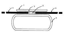
図1は本発明の一実施形態を示す接合部断面図である。本発明における放熱板とヒートパイプの接合形態を図1を用いて説明する。
【0015】
ヒートパイプ8は図示のように断面が長円形に形成されたヒートパイプコンテナ5の内部に、作動流体とウイックが封入されているものである。この長円形のヒートパイプコンテナ5の平坦部上にインサートプレート2を置き、熱を全体に行き渡らせるため、ヒートパイプコンテナ5から直交するようカーボンカーボンの繊維の方向を合わせ、このインサートプレート2の左右に二枚のカーボンカーボン板4、4を配置する。それと共に、インサートプレート2とカーボンカーボン板4、4の2か所の接合部の上部にカバープレート1を設け、図1中の3の斜線の部分のようにこれら接合部にろう材を配置して真空ろう付け接合3する。
【0016】
次に本発明の作用を述べる。
【0017】
本発明において、カバープレート1とインサートプレート2間及びインサートプレート2とヒートパイプコンテナ5間は、それぞれ金属間でろう付け接合3される。これにより、カーボンカーボン板4、4をヒートパイプコンテナ5とカバ−プレート1で挟持し、カーボンカーボン板4、4が両面で支えられるため、接合部の接合強度を高めることができ、カーボンカーボン自体の繊維が剥れない。また、ヒートパイプコンテナ5の形状を長円形にすることにより、ろう付け3面積を大きくして、接合強度をより高め、カーボンカーボン板4自体の繊維が剥れることはない。
【0018】
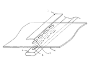
図2は本発明の他の実施形態を示す分解組み立て図である。この形態は図に示すように取り付け用の穴7を設けたカーボンカーボン板4を用いるもので、取り付け用の穴7をヒートパイプ8に沿う様に、カーボンカーボン板4をヒートパイプ8の長円形の平坦部に置く、そして、取り付け穴7にインサートプレート2を設置し、カバープレート1でインサートプレート2とカーボンカーボン板4の接合部上に、取り付け穴7に沿うように置いてカバープレート1、カーボンカーボン板4、インサートプレ−ト2及びヒートパイプ8の接合部を真空ろう付け接合3する。
【0019】
また、インサートプレート2は必ずしも単体の独立したものである必要はなく、インサートプレート2に該当する凸部を持つカバープレートやインサートプレート2に該当する凸部を持つヒートパイプでもかまわない。
【0020】
さらに、カーボンカーボンの密度がアルミニウムの密度の約75%程度であるため、放熱板4用材料の単位質量当たりの排熱量を増加することができ、よって、放熱板4の単位面積当りの排熱量も増加することとなる。つまり、従来のラジエータと比較して小形化も実現でき、より高性能な宇宙用ラジエータを提供することができる。
【0021】
【発明の効果】
以上要するに本発明によれば、カバープレート1とインサートプレート2間及びインサートプレート2とヒートパイプコンテナ5間は、それぞれ金属間でろう付け接合3される。これにより、カーボンカーボン板4、4をヒートパイプコンテナ5とカバ−プレート1で挟持し、カーボンカーボン板4、4が両面で支えられるため、接合部の接合強度を高めることができ、カーボンカーボン自体の繊維が剥れない。また、ヒートパイプコンテナ5の形状を長円形にすることにより、ろう付け3面積を大きくして、接合強度をより高め、カーボンカーボン板4自体の繊維が剥れることはない。
【図面の簡単な説明】
【図1】本発明の一実施形態を示す接合部断面図である。
【図2】本発明の他の実施形態を示す分解組み立て図である。
【図3】本発明の前提となる宇宙用ラジエータの模式図である。
【符号の説明】
1 カバープレート
2 インサートプレート
3 ろう材
4 カーボンカーボン板(放熱板)
5 ヒートパイプコンテナ
6 カーボン繊維方向
7 取り付け穴
8 ヒートパイプ[0001]
BACKGROUND OF THE INVENTION
The present invention relates to a space radiator for exhausting heat using a heat pipe and a heat radiating plate.
[0002]
[Prior art]
Conventionally, heat generated inside an artificial satellite or the like in space is exhausted by a radiator as shown in FIGS. 3A is a front view of the space radiator, FIG. 3B is a top view of the space radiator, and FIG. 3C is a side view of the space radiator.
[0003]
As shown in FIG. 3, this radiator has a
[0004]
Then, paying attention to the high thermal conductivity of carbon carbon, in recent years, the use of this carbon carbon as a material for the
[0005]
A space radiator using carbon carbon will be described with reference to FIG. First, even when carbon carbon is used, the appearance is almost the same as in FIG. 3 (a). In the figure, the
[0006]
[Problems to be solved by the invention]
However, carbon carbon, in which the direction of a large number of carbon fibers is oriented in one direction and hardened with carbon, is strong against bending and shearing forces in the fiber direction, but weak against bending and shearing forces perpendicular to the fiber direction. When an impact is applied, the fibers peel off in layers. Therefore, in the form of vacuum brazing 3 as described above, even if the bonding strength of the surface of the carbon carbon brazed 3 is high, the carbon carbon fiber itself is peeled off in layers after impact. Therefore, in practice, carbon carbon is not used for high impact applications.
[0007]
Accordingly, the object of the present invention is to solve the above-mentioned problems, use a carbon carbon plate as a heat sink, improve the bonding strength by bonding the carbon carbon plate and the heat pipe well, and the fibers of the carbon carbon itself peel off due to impact. There is no space radiator to provide.
[0008]
[Means for Solving the Problems]
In order to achieve the above object, the present invention of
[0009]
The present invention of
[0010]
According to the third aspect of the present invention, the carbon carbon plate is formed by orienting a number of carbon fibers in one direction and solidifying the carbon fibers with carbon, and the carbon fibers of the carbon carbon plate are orthogonal to the heat pipe in plan view. space radiator according to
[0011]
According to the fourth aspect of the present invention, the cross section of the pipe container of the heat pipe is formed in an oval shape, and the insert plate is disposed on the oval flat portion, and the pipe container, the carbon carbon plate, and the cover plate are vacuum brazed. The space radiator according to any one of
[0013]
DETAILED DESCRIPTION OF THE INVENTION
Hereinafter, a preferred embodiment of the present invention will be described in detail with reference to the accompanying drawings.
[0014]
FIG. 1 is a cross-sectional view of a joint showing an embodiment of the present invention. The joining form of the heat sink and heat pipe in the present invention will be described with reference to FIG.
[0015]
As shown in the figure, the heat pipe 8 is one in which a working fluid and a wick are enclosed in a
[0016]
Next, the operation of the present invention will be described.
[0017]
In the present invention, the
[0018]
FIG. 2 is an exploded view showing another embodiment of the present invention. In this embodiment, as shown in the figure, a
[0019]
Further, the
[0020]
Furthermore, since the density of carbon carbon is about 75% of the density of aluminum, the amount of heat exhausted per unit mass of the material for the
[0021]
【The invention's effect】
In short, according to the present invention, the
[Brief description of the drawings]
FIG. 1 is a cross-sectional view of a joint showing an embodiment of the present invention.
FIG. 2 is an exploded view showing another embodiment of the present invention.
FIG. 3 is a schematic diagram of a space radiator as a premise of the present invention.
[Explanation of symbols]
1 Cover
5
Claims (4)
Priority Applications (1)
| Application Number | Priority Date | Filing Date | Title |
|---|---|---|---|
| JP27391298A JP4290786B2 (en) | 1998-09-28 | 1998-09-28 | Space radiator |
Applications Claiming Priority (1)
| Application Number | Priority Date | Filing Date | Title |
|---|---|---|---|
| JP27391298A JP4290786B2 (en) | 1998-09-28 | 1998-09-28 | Space radiator |
Publications (2)
| Publication Number | Publication Date |
|---|---|
| JP2000103400A JP2000103400A (en) | 2000-04-11 |
| JP4290786B2 true JP4290786B2 (en) | 2009-07-08 |
Family
ID=17534311
Family Applications (1)
| Application Number | Title | Priority Date | Filing Date |
|---|---|---|---|
| JP27391298A Expired - Fee Related JP4290786B2 (en) | 1998-09-28 | 1998-09-28 | Space radiator |
Country Status (1)
| Country | Link |
|---|---|
| JP (1) | JP4290786B2 (en) |
Families Citing this family (2)
| Publication number | Priority date | Publication date | Assignee | Title |
|---|---|---|---|---|
| CN104386266B (en) * | 2014-09-18 | 2016-06-08 | 北京卫星环境工程研究所 | Satellite ground payload heat abstractor |
| CN113562201A (en) * | 2021-07-21 | 2021-10-29 | 北京空间飞行器总体设计部 | Light high-temperature heat pipe radiator for space |
-
1998
- 1998-09-28 JP JP27391298A patent/JP4290786B2/en not_active Expired - Fee Related
Also Published As
| Publication number | Publication date |
|---|---|
| JP2000103400A (en) | 2000-04-11 |
Similar Documents
| Publication | Publication Date | Title |
|---|---|---|
| US5729995A (en) | Electronic component cooling unit | |
| JP3146158U (en) | Heat dissipation module | |
| US6862183B2 (en) | Composite fins for heat sinks | |
| KR900005281B1 (en) | Solar water heater incorporating heat pipe | |
| US7273094B2 (en) | Cooling fin unit | |
| JP4290786B2 (en) | Space radiator | |
| JPH05141889A (en) | Heat exchanger | |
| TWI305132B (en) | ||
| JP2005203665A5 (en) | ||
| JPS61122493A (en) | Plate type heat exchanger | |
| JPH10224068A (en) | Heat-pipe-type heat sink | |
| TWM629434U (en) | Structure of heat-dissipating module | |
| JP2009092357A (en) | Tabular heat pipe | |
| JP2676835B2 (en) | Spacecraft heat dissipation structure | |
| JP4332261B2 (en) | Heat transport equipment | |
| JPH09203595A (en) | Radiator device | |
| JPH0510209Y2 (en) | ||
| JP3694353B2 (en) | Cooling pipe embedded plate | |
| JP4239370B2 (en) | Manufacturing method of flat heat pipe | |
| JPH11274782A (en) | Heat radiator utilizing heat pipe | |
| KR102457713B1 (en) | Vapor chamber with clad material and manufacturing method thereof | |
| JPH06828Y2 (en) | Heat pipe radiator for semiconductors | |
| JP2004241450A (en) | Heat sink | |
| JPH10132478A (en) | Heat pipe type radiator | |
| JP3694351B2 (en) | Radiator and manufacturing method thereof |
Legal Events
| Date | Code | Title | Description |
|---|---|---|---|
| A621 | Written request for application examination |
Free format text: JAPANESE INTERMEDIATE CODE: A621 Effective date: 20050920 |
|
| A977 | Report on retrieval |
Free format text: JAPANESE INTERMEDIATE CODE: A971007 Effective date: 20080117 |
|
| A131 | Notification of reasons for refusal |
Free format text: JAPANESE INTERMEDIATE CODE: A131 Effective date: 20080408 |
|
| A521 | Request for written amendment filed |
Free format text: JAPANESE INTERMEDIATE CODE: A523 Effective date: 20080521 |
|
| RD02 | Notification of acceptance of power of attorney |
Free format text: JAPANESE INTERMEDIATE CODE: A7422 Effective date: 20080521 |
|
| A521 | Request for written amendment filed |
Free format text: JAPANESE INTERMEDIATE CODE: A821 Effective date: 20080521 |
|
| A131 | Notification of reasons for refusal |
Free format text: JAPANESE INTERMEDIATE CODE: A131 Effective date: 20080729 |
|
| A521 | Request for written amendment filed |
Free format text: JAPANESE INTERMEDIATE CODE: A523 Effective date: 20080819 |
|
| TRDD | Decision of grant or rejection written | ||
| A01 | Written decision to grant a patent or to grant a registration (utility model) |
Free format text: JAPANESE INTERMEDIATE CODE: A01 Effective date: 20090324 |
|
| A01 | Written decision to grant a patent or to grant a registration (utility model) |
Free format text: JAPANESE INTERMEDIATE CODE: A01 |
|
| A61 | First payment of annual fees (during grant procedure) |
Free format text: JAPANESE INTERMEDIATE CODE: A61 Effective date: 20090402 |
|
| R150 | Certificate of patent or registration of utility model |
Free format text: JAPANESE INTERMEDIATE CODE: R150 |
|
| FPAY | Renewal fee payment (event date is renewal date of database) |
Free format text: PAYMENT UNTIL: 20120410 Year of fee payment: 3 |
|
| FPAY | Renewal fee payment (event date is renewal date of database) |
Free format text: PAYMENT UNTIL: 20120410 Year of fee payment: 3 |
|
| FPAY | Renewal fee payment (event date is renewal date of database) |
Free format text: PAYMENT UNTIL: 20130410 Year of fee payment: 4 |
|
| FPAY | Renewal fee payment (event date is renewal date of database) |
Free format text: PAYMENT UNTIL: 20130410 Year of fee payment: 4 |
|
| FPAY | Renewal fee payment (event date is renewal date of database) |
Free format text: PAYMENT UNTIL: 20140410 Year of fee payment: 5 |
|
| R250 | Receipt of annual fees |
Free format text: JAPANESE INTERMEDIATE CODE: R250 |
|
| R250 | Receipt of annual fees |
Free format text: JAPANESE INTERMEDIATE CODE: R250 |
|
| R250 | Receipt of annual fees |
Free format text: JAPANESE INTERMEDIATE CODE: R250 |
|
| LAPS | Cancellation because of no payment of annual fees |


