JP4290771B2 - Ink volume sensing and replenishment system - Google Patents
Ink volume sensing and replenishment system Download PDFInfo
- Publication number
- JP4290771B2 JP4290771B2 JP29442096A JP29442096A JP4290771B2 JP 4290771 B2 JP4290771 B2 JP 4290771B2 JP 29442096 A JP29442096 A JP 29442096A JP 29442096 A JP29442096 A JP 29442096A JP 4290771 B2 JP4290771 B2 JP 4290771B2
- Authority
- JP
- Japan
- Prior art keywords
- ink
- tank
- carriage
- sensing
- level
- Prior art date
- Legal status (The legal status is an assumption and is not a legal conclusion. Google has not performed a legal analysis and makes no representation as to the accuracy of the status listed.)
- Expired - Fee Related
Links
- 239000012528 membrane Substances 0.000 claims description 15
- 230000003287 optical effect Effects 0.000 claims description 10
- 238000007639 printing Methods 0.000 claims description 7
- 238000001514 detection method Methods 0.000 claims description 2
- 230000000087 stabilizing effect Effects 0.000 claims 1
- 239000000976 ink Substances 0.000 description 280
- 230000000875 corresponding effect Effects 0.000 description 8
- 230000006870 function Effects 0.000 description 7
- 239000007788 liquid Substances 0.000 description 7
- 238000000034 method Methods 0.000 description 7
- 239000000463 material Substances 0.000 description 5
- 238000012544 monitoring process Methods 0.000 description 5
- 238000005192 partition Methods 0.000 description 5
- LYCAIKOWRPUZTN-UHFFFAOYSA-N Ethylene glycol Chemical compound OCCO LYCAIKOWRPUZTN-UHFFFAOYSA-N 0.000 description 4
- 230000008859 change Effects 0.000 description 4
- 230000000630 rising effect Effects 0.000 description 4
- 239000002699 waste material Substances 0.000 description 3
- 241000405070 Percophidae Species 0.000 description 2
- 238000004364 calculation method Methods 0.000 description 2
- 238000011109 contamination Methods 0.000 description 2
- 230000001276 controlling effect Effects 0.000 description 2
- 229920001971 elastomer Polymers 0.000 description 2
- 239000000806 elastomer Substances 0.000 description 2
- 238000004836 empirical method Methods 0.000 description 2
- 239000012530 fluid Substances 0.000 description 2
- WGCNASOHLSPBMP-UHFFFAOYSA-N hydroxyacetaldehyde Natural products OCC=O WGCNASOHLSPBMP-UHFFFAOYSA-N 0.000 description 2
- 239000012535 impurity Substances 0.000 description 2
- 230000000149 penetrating effect Effects 0.000 description 2
- 239000000088 plastic resin Substances 0.000 description 2
- 230000006641 stabilisation Effects 0.000 description 2
- 238000011105 stabilization Methods 0.000 description 2
- 238000003466 welding Methods 0.000 description 2
- 241000272525 Anas platyrhynchos Species 0.000 description 1
- 229920000544 Gore-Tex Polymers 0.000 description 1
- 239000004809 Teflon Substances 0.000 description 1
- 229920006362 Teflon® Polymers 0.000 description 1
- 238000013459 approach Methods 0.000 description 1
- 230000002238 attenuated effect Effects 0.000 description 1
- 230000033228 biological regulation Effects 0.000 description 1
- 230000005540 biological transmission Effects 0.000 description 1
- 230000006835 compression Effects 0.000 description 1
- 238000007906 compression Methods 0.000 description 1
- 230000008602 contraction Effects 0.000 description 1
- 230000002596 correlated effect Effects 0.000 description 1
- 238000005336 cracking Methods 0.000 description 1
- 230000007423 decrease Effects 0.000 description 1
- 238000010586 diagram Methods 0.000 description 1
- 230000003467 diminishing effect Effects 0.000 description 1
- 238000005516 engineering process Methods 0.000 description 1
- 230000007613 environmental effect Effects 0.000 description 1
- 238000002347 injection Methods 0.000 description 1
- 239000007924 injection Substances 0.000 description 1
- 238000003780 insertion Methods 0.000 description 1
- 230000037431 insertion Effects 0.000 description 1
- 238000012423 maintenance Methods 0.000 description 1
- 238000012067 mathematical method Methods 0.000 description 1
- 239000012229 microporous material Substances 0.000 description 1
- 238000012986 modification Methods 0.000 description 1
- 230000004048 modification Effects 0.000 description 1
- 230000000737 periodic effect Effects 0.000 description 1
- 239000004033 plastic Substances 0.000 description 1
- 230000008569 process Effects 0.000 description 1
- 238000012545 processing Methods 0.000 description 1
- 230000004044 response Effects 0.000 description 1
- 238000007789 sealing Methods 0.000 description 1
- 239000000243 solution Substances 0.000 description 1
- 229910001220 stainless steel Inorganic materials 0.000 description 1
- 239000010935 stainless steel Substances 0.000 description 1
Images


Classifications
-
- B—PERFORMING OPERATIONS; TRANSPORTING
- B41—PRINTING; LINING MACHINES; TYPEWRITERS; STAMPS
- B41J—TYPEWRITERS; SELECTIVE PRINTING MECHANISMS, i.e. MECHANISMS PRINTING OTHERWISE THAN FROM A FORME; CORRECTION OF TYPOGRAPHICAL ERRORS
- B41J2/00—Typewriters or selective printing mechanisms characterised by the printing or marking process for which they are designed
- B41J2/005—Typewriters or selective printing mechanisms characterised by the printing or marking process for which they are designed characterised by bringing liquid or particles selectively into contact with a printing material
- B41J2/01—Ink jet
- B41J2/17—Ink jet characterised by ink handling
- B41J2/175—Ink supply systems ; Circuit parts therefor
- B41J2/17503—Ink cartridges
- B41J2/17513—Inner structure
-
- B—PERFORMING OPERATIONS; TRANSPORTING
- B41—PRINTING; LINING MACHINES; TYPEWRITERS; STAMPS
- B41J—TYPEWRITERS; SELECTIVE PRINTING MECHANISMS, i.e. MECHANISMS PRINTING OTHERWISE THAN FROM A FORME; CORRECTION OF TYPOGRAPHICAL ERRORS
- B41J2/00—Typewriters or selective printing mechanisms characterised by the printing or marking process for which they are designed
- B41J2/005—Typewriters or selective printing mechanisms characterised by the printing or marking process for which they are designed characterised by bringing liquid or particles selectively into contact with a printing material
- B41J2/01—Ink jet
- B41J2/17—Ink jet characterised by ink handling
- B41J2/175—Ink supply systems ; Circuit parts therefor
- B41J2/17503—Ink cartridges
- B41J2/1752—Mounting within the printer
- B41J2/17523—Ink connection
-
- B—PERFORMING OPERATIONS; TRANSPORTING
- B41—PRINTING; LINING MACHINES; TYPEWRITERS; STAMPS
- B41J—TYPEWRITERS; SELECTIVE PRINTING MECHANISMS, i.e. MECHANISMS PRINTING OTHERWISE THAN FROM A FORME; CORRECTION OF TYPOGRAPHICAL ERRORS
- B41J2/00—Typewriters or selective printing mechanisms characterised by the printing or marking process for which they are designed
- B41J2/005—Typewriters or selective printing mechanisms characterised by the printing or marking process for which they are designed characterised by bringing liquid or particles selectively into contact with a printing material
- B41J2/01—Ink jet
- B41J2/17—Ink jet characterised by ink handling
- B41J2/175—Ink supply systems ; Circuit parts therefor
- B41J2/17503—Ink cartridges
- B41J2/17526—Electrical contacts to the cartridge
-
- B—PERFORMING OPERATIONS; TRANSPORTING
- B41—PRINTING; LINING MACHINES; TYPEWRITERS; STAMPS
- B41J—TYPEWRITERS; SELECTIVE PRINTING MECHANISMS, i.e. MECHANISMS PRINTING OTHERWISE THAN FROM A FORME; CORRECTION OF TYPOGRAPHICAL ERRORS
- B41J2/00—Typewriters or selective printing mechanisms characterised by the printing or marking process for which they are designed
- B41J2/005—Typewriters or selective printing mechanisms characterised by the printing or marking process for which they are designed characterised by bringing liquid or particles selectively into contact with a printing material
- B41J2/01—Ink jet
- B41J2/17—Ink jet characterised by ink handling
- B41J2/175—Ink supply systems ; Circuit parts therefor
- B41J2/17503—Ink cartridges
- B41J2/17536—Protection of cartridges or parts thereof, e.g. tape
-
- B—PERFORMING OPERATIONS; TRANSPORTING
- B41—PRINTING; LINING MACHINES; TYPEWRITERS; STAMPS
- B41J—TYPEWRITERS; SELECTIVE PRINTING MECHANISMS, i.e. MECHANISMS PRINTING OTHERWISE THAN FROM A FORME; CORRECTION OF TYPOGRAPHICAL ERRORS
- B41J2/00—Typewriters or selective printing mechanisms characterised by the printing or marking process for which they are designed
- B41J2/005—Typewriters or selective printing mechanisms characterised by the printing or marking process for which they are designed characterised by bringing liquid or particles selectively into contact with a printing material
- B41J2/01—Ink jet
- B41J2/17—Ink jet characterised by ink handling
- B41J2/175—Ink supply systems ; Circuit parts therefor
- B41J2/17503—Ink cartridges
- B41J2/17553—Outer structure
-
- B—PERFORMING OPERATIONS; TRANSPORTING
- B41—PRINTING; LINING MACHINES; TYPEWRITERS; STAMPS
- B41J—TYPEWRITERS; SELECTIVE PRINTING MECHANISMS, i.e. MECHANISMS PRINTING OTHERWISE THAN FROM A FORME; CORRECTION OF TYPOGRAPHICAL ERRORS
- B41J2/00—Typewriters or selective printing mechanisms characterised by the printing or marking process for which they are designed
- B41J2/005—Typewriters or selective printing mechanisms characterised by the printing or marking process for which they are designed characterised by bringing liquid or particles selectively into contact with a printing material
- B41J2/01—Ink jet
- B41J2/17—Ink jet characterised by ink handling
- B41J2/175—Ink supply systems ; Circuit parts therefor
- B41J2/17503—Ink cartridges
- B41J2/17556—Means for regulating the pressure in the cartridge
-
- B—PERFORMING OPERATIONS; TRANSPORTING
- B41—PRINTING; LINING MACHINES; TYPEWRITERS; STAMPS
- B41J—TYPEWRITERS; SELECTIVE PRINTING MECHANISMS, i.e. MECHANISMS PRINTING OTHERWISE THAN FROM A FORME; CORRECTION OF TYPOGRAPHICAL ERRORS
- B41J2/00—Typewriters or selective printing mechanisms characterised by the printing or marking process for which they are designed
- B41J2/005—Typewriters or selective printing mechanisms characterised by the printing or marking process for which they are designed characterised by bringing liquid or particles selectively into contact with a printing material
- B41J2/01—Ink jet
- B41J2/17—Ink jet characterised by ink handling
- B41J2/175—Ink supply systems ; Circuit parts therefor
- B41J2/17566—Ink level or ink residue control
-
- G—PHYSICS
- G01—MEASURING; TESTING
- G01F—MEASURING VOLUME, VOLUME FLOW, MASS FLOW OR LIQUID LEVEL; METERING BY VOLUME
- G01F23/00—Indicating or measuring liquid level or level of fluent solid material, e.g. indicating in terms of volume or indicating by means of an alarm
- G01F23/22—Indicating or measuring liquid level or level of fluent solid material, e.g. indicating in terms of volume or indicating by means of an alarm by measuring physical variables, other than linear dimensions, pressure or weight, dependent on the level to be measured, e.g. by difference of heat transfer of steam or water
- G01F23/28—Indicating or measuring liquid level or level of fluent solid material, e.g. indicating in terms of volume or indicating by means of an alarm by measuring physical variables, other than linear dimensions, pressure or weight, dependent on the level to be measured, e.g. by difference of heat transfer of steam or water by measuring the variations of parameters of electromagnetic or acoustic waves applied directly to the liquid or fluent solid material
- G01F23/284—Electromagnetic waves
- G01F23/292—Light, e.g. infrared or ultraviolet
- G01F23/2921—Light, e.g. infrared or ultraviolet for discrete levels
-
- B—PERFORMING OPERATIONS; TRANSPORTING
- B41—PRINTING; LINING MACHINES; TYPEWRITERS; STAMPS
- B41J—TYPEWRITERS; SELECTIVE PRINTING MECHANISMS, i.e. MECHANISMS PRINTING OTHERWISE THAN FROM A FORME; CORRECTION OF TYPOGRAPHICAL ERRORS
- B41J2/00—Typewriters or selective printing mechanisms characterised by the printing or marking process for which they are designed
- B41J2/005—Typewriters or selective printing mechanisms characterised by the printing or marking process for which they are designed characterised by bringing liquid or particles selectively into contact with a printing material
- B41J2/01—Ink jet
- B41J2/17—Ink jet characterised by ink handling
- B41J2/175—Ink supply systems ; Circuit parts therefor
- B41J2/17503—Ink cartridges
- B41J2/17513—Inner structure
- B41J2002/17516—Inner structure comprising a collapsible ink holder, e.g. a flexible bag
Description
【0001】
【発明の分野】
本発明は、一般的に、インク・ジェット・プリンタやプロッタ等の、高速でコンピュータが駆動するプリンタのプリントヘッドのインク供給に関する。本発明は、より詳細には、インクを引き出すキャリッジに搭載されたプリントヘッドに供給するプリンタのキャリッジに搭載されたインク槽における、プリンタのキャリッジから離れた静止した供給インクからキャリッジに搭載されたインク槽に導くインク補充を特徴とするインク供給システムに関する。
【0002】
【関連技術の説明】
コンピュータが駆動するインク・ジェット・プリンタやプロッタにおいては、供給インクは通常プリントヘッドにすぐ隣接するプリントヘッドのキャリッジ上の槽内に保持され、準備のできた供給インクをプリントヘッドに供給する。この槽は、通常、単一のカートリッジ内で、プリントヘッドと組み合わされている。かかるプリンタにおいて、例えば、この「搭載されている」インク槽は、通常、大気圧より低い、すなわち負の圧力に維持されていて、インクがプリントヘッドから漏れたり「垂れ」たりしないようになっている。従来、補充することのできるインク槽のカートリッジを含む、様々なタイプのインク槽が用いられている。この補充することのインク槽のカートリッジは、移動可能なプリンタのキャリッジ上に搭載されている、使い捨ての取り替え可能のカートリッジであり、搭載されているインク槽と、離れた、つまり「搭載されていない」インク槽の組み合わせである。搭載されていない供給インクが用いられるときには、インクは引き出されてプリントヘッドのユニットつまりカートリッジに供給されるが、これは通常、今言及した搭載されているインク槽を組み込んでいる。インクは、搭載されていないインク供給槽から、例えば柔軟性を有する配管を経由してキャリッジに搭載されたプリントヘッドのユニットに運ぶことができる。
【0003】
特に、ある知られているインクのカートリッジは、その中に含まれたばねによって2つの側板が離れる方向にバイアスされている、柔軟性のある膜状のシート材で形成された袋を含む、「ばね袋」の内部インク槽を用いている。ばねは袋の容積を増大する(そして収縮に抵抗する)傾向があり、内部の大気圧より低い圧力を維持する。かかるカートリッジに関するさらなる情報は、すべて本出願の譲受人に譲渡されておりその言及によって本明細書に組み込まれる、1994年1月18日にFong他に対して発行された米国特許番号第5,280,300号、1994年6月28日にFongに対して発行された米国特許番号第5,325,119号、および1994年10月25日にHunt他に対して発行された米国特許番号第5,359,353号、において得ることができる。
【0004】
使い捨て式のインクのカートリッジ、そして可能な限りにおいて、無駄なインク、を省くことが、無駄なインクおよびインク容器の処分に関する環境問題に鑑みて、そしてさらに、プリンタおよびプロッタのユーザの購入および運転コストを低くするということに鑑みて、望ましい目的である。プリンタ機器のオペレータが供給インクを補充する時間間隔を長くすることができ、使用済のインクのカートリッジまたはインクを処理する頻度が高くならないので、容易に補充することができる搭載されていないインク供給容器を備えることがこの方向での重要な段階である。
【0005】
かかる搭載されていない供給インクおよび搭載されているインク槽を備えることについては、直面してきた困難がある。特に、搭載されているインクのばね袋の槽内での準備のできた供給量のインクは、ある限界内に保たねばならず、それと同時に、袋内の負圧を保たねばならない。この過程は困難である、というのも、袋内の圧力が大気圧まで上がってしまうことを防ぐために、インクを槽内に注入することを規制せねばならず、搭載されている槽の袋内のインク体積を注意深く監視せねばならないからである。インク体積を監視することへの解決法のひとつは、「滴をカウントすること」、すなわち、インクの個々の噴出をカウントすることによって、プリントヘッドから噴出されたインクの量を監視することである。この滴のカウントおよび他の試みられた公知の方法では、正確な結果がもたらされていなかった。
【0006】
さらに、プリンタが適切に動作することを確実にするために、供給インクの補充に関して、空気のプリントヘッド内への導入は防止せねばならない。さらに、プリントヘッドのキャリッジの運動、そしてその結果、搭載されていない供給インクと搭載されている槽の間をつなぐ柔軟性を有する管路により、運ばれているインクの圧力および送り出し速度におけるゆらぎが起こり、管路を越えてくる空気の泡が搭載されている槽を汚染することも促進される。こういった状況は、空気が搭載されている槽に入りプリントヘッドに引き込まれる場合、またはかかる圧力または流れのゆらぎによって内部圧力が大気圧にまたはそれ以上に上昇してインクがプリントヘッドから垂れる場合に、プリントヘッドが適切に機能することを危うくする可能性がある。
【0007】
こういった困難を認識して、本発明は、無理のない低コストで、搭載されているインク槽を補充するシステムを提供し、それによって廃棄物を減少させることに向けられている。より詳細には、大気圧より低い圧力に維持された搭載されているインク槽と共に用いるようになっており、搭載されている槽内のインク体積を監視することおよびその槽を必要に応じて制御された方法で補充することを含む、システムが提供される。
【0008】
【発明の概要】
従って、本発明は、通路に沿って移動可能なプリントヘッドのキャリッジを有するコンピュータで駆動されるプリンタにおける、プリンタのキャリッジに搭載されたインク槽のインクレベルを感知する装置であって、前記通路に沿った前記プリントヘッドのキャリッジの位置が前記プリンタによって検出可能である、装置において、前記キャリッジに搭載されたインク槽は、剛性の外部ハウジングと、前記剛性の外部ハウジング内に収納される可動壁を含み、前記剛性の外部ハウジングに対して移動可能である内部槽とを有し、前記内部槽は前記剛性の外部ハウジング内に可変体積室を確定し、前記剛性の外部ハウジングはインクレベル表示が前記可動壁を含むインクレベルインジケータによって与えられるところのインク視位置を含み、前記インクレベルインジケータと前記インク視位置とは、前記インクレベルインジケータが前記剛性の外部ハウジングの外側から前記インク視位置へ向けられた光ビームによって照らされるように構成され、前記インクレベルインジケータの位置は前記可動壁とともに移動可能であり、前記インクレベルインジケータの位置は前記キャリッジに搭載されたインク槽内のインクの体積に対する相関を有し、前記インクの体積が前記インクレベルインジケータ及び前記剛性の外部ハウジングの相対位置から判定され、前記キャリッジに搭載されたインク槽の前記通路と平行な方向に所定の幅を有するインク感知領域であって、前記キャリッジに搭載されたインク槽が前記キャリッジとともに通過するインク感知領域と、前記光ビームは、前記インク感知領域内で前記通路を横切る向きを向いており、前記インク槽が前記インク感知領域を通過するとき前記インク視位置に到達し、前記光ビームを検出する光センサであって、前記検出される光は前記キャリッジに搭載されたインク槽の前記インク視位置において前記インクレベルインジケータによって前記光ビームが遮蔽されることで変化し、前記インクレベルインジケータの位置が検出される、光センサと、前記インクレベルインジケータの位置が検出された時点で、このときの前記剛性の外部ハウジングの前記通路に平行な方向の位置を検出する手段と、前記検出されたインクレベルインジケータの位置と前記検出された剛性のハウジングの位置とを比較する手段であって、これによりインクの体積が判定可能である、比較する手段とを備える装置を提供する。
【0009】
より詳細な1態様において、柔軟性を有するインク供給ラインを有するインク管路が、搭載されていないインク供給容器とキャリッジに搭載された供給インクの間に配置されている。圧力および流れの制限および安定化手段を含む構造がインク補充システムに組み込まれており、キャリッジに搭載された槽に隣接して配置され、補充されるキャリッジに搭載された槽に制御された流れのインクを与え、キャリッジに搭載された槽が1補充サイクルの間ずっと大気圧より低い圧力のままであることができる。この流れの制限および安定化手段は、狭窄した流体の管路を含むことができ、さらに、キャリッジに搭載されたインク槽と柔軟性を有する供給ラインの間の針と隔壁のコネクタの内腔(inner lumen)によって規定されてもよい。さらに、前記管路内には、立ち上がり管(riser)および一方向通気孔を含む空気タンクが組み込まれており、空気がプリントヘッドに達することを防止している。一方向通気孔によって、空気は空気タンクを出ることができるが、インクの逃げや空気その他の不純物の入り込みは防止される。
【0010】
さらにより詳細な態様において、光源および光電センサを用いてインクレベルを感知することができる。インク槽のハウジングにおける開口部によって、カートリッジを貫き、内部のばね袋のインク槽の移動可能な壁を含むインクレベルを観察することができる一筋の視野が与えられる。開口部は、様々な位置のインクレベルを観察することができるような大きさになっており、プリンタのキャリッジ上に搭載されると、インクレベルは、光源が放ち光電センサが受け取る光の変化によって感知することができる。キャリッジが光電センサを通り過ぎて移動すると、光源からセンサへの直線(direct line)に位置するインクのレベルが検出され、光の変化によってキャリッジ位置が感知され、カートリッジの位置は、光学的エンコーダ・バーおよびそれに関連する光学的センサを参照してキャリッジ位置モニタに基づいて知られる。こういった各要素の相対的位置がこのように感知されるので、カートリッジの残りの部分に関するインクレベル位置の既知の関係に従って、インク体積が決定される。
【0011】
【発明の実施例】
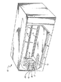
図面はすべて限定としてではなく例として与えられたものであるが、そのうちの図1を参照して、当業者に公知のとおり非常に小さなインクの噴出によって印字が行われるインク・ジェットタイプのコンピュータが駆動するプリンタ10は、支持具14、15上に摺動可能に支持されるキャリッジ12、および光学的スキャナ(図示せず)と共にキャリッジの位置を監視するエンコーダ・バー16を含む。搭載されているプリントヘッドおよびインク槽のカートリッジ17、18、19、20は、キャリッジ上に搭載され、それぞれが、例えば、カラーのインク(例えばシアン、マゼンタ、またはイエロー)、またはブラックのインクを含み、例えばカラーの印字およびブラックのインクのみの印字ができるようにしている。本説明上は単一のインクのカートリッジについて言及するが、この説明が、示されるいかなるそしてすべてのインクのカートリッジにも適用することができるのは、明白となろう。
【0012】
図2に本発明のインクのカートリッジ20を示す。カートリッジは、鋳造した堅いプラスチック樹脂の外部ハウジング22を含む。外部ハウジングは、ハウジングの残りの部分にセメント付けまたは溶接によって固定することを意図した蓋板24を有する。カートリッジは、その一番下の端壁にインク放出開口部(図示せず)を有しており、そこには電気的に駆動されるプリントヘッド26が固定されている。第1の側32における第1のスロット30および、図3において見えるように、第1のスロットと整列し第1の側から第2の反対の側36へハウジングを貫いて一筋の視野を与える第2のスロット34によって規定される、ハウジング22における不連続によって、視位置28が規定される。
【0013】
図2および図3の両方を参照して、インク供給ライン38は、コネクタを経由してカートリッジ20に接続することができる。コネクタは、本実施例においては、インクに関して不活性のエラストマー材で形成されハウジング22内の開口部42に配置された隔壁40、および隔壁を突き刺すようになっている針44を含む。このコネクタによって、空気その他の不純物による汚染のない接続を行うことができる。針を貫く内腔を含む毛管(図示せず)はまた、柔軟性を有する供給ライン38からのカートリッジ20内の搭載されているインク槽のインク補充に関する圧力および流れのゆらぎの制限器としての役割も果たし、流れを、カートリッジ20のインク槽内の圧力を予め選択した大気圧より低い圧力以上に上昇させるような量よりも小さい量に安定化する。隔壁には、予め細長い切り込みを入れて、先端が比較的丸い針が接続できるようにしていてもよく、隔壁は圧縮的に装填されて、針44の挿入によって針44が引っ込められたときにそこを貫いて形成されるいかなる開口もシールすることができる。
【0014】
インク供給ライン38内には、コネクタの針44に隣接して空気タンク46が組み込まれており、空気タンクは、立ち上がり管48、および多孔性の膜によって形成され空気は通すがインクは通さない空気弁50を含む。空気が逃げることができるように小さな開口部54を組み込んだ蓋板52は、立ち上がり管48のてっぺんを閉じている。膜の上には、グリコール等の不揮発性の液体の層57が配置されており、たとえタンク46の立ち上がり管48の内部に真空がかかって内部圧力が大気圧よりも低い圧力に下がるとしても、空気が膜を通って立ち上がり管内に浸透することを防止する。または、あるいは液体の層57を設けることに加えて、閉位置にバイアスされたフラッパまたはダックビル弁等の逆止弁(図示せず)を設けてもよい。逆止弁は蓋板の開口部54を制御して、立ち上がり管から空気は逃げることができるが立ち上がり管内の圧力が大気圧よりも低くなった場合も空気が立ち上がり管に引き込まれることを防止する。空気タンクが適切に機能して気泡を捕らえるためには、立ち上がり管が比較的垂直に立ったままでいることが不可欠なので、ハウジング22内には水平の出っ張り58が組み込まれていて、空気タンク46が針のコネクタの中央軸の回りを回転することが防止される。
【0015】
図示しないさらなる実施例において、従来のダックビルまたはフラッパ逆止弁等の一方向弁や、フロート弁と逆止弁の組み合わせが、膜の空気弁の代わりになる。
【0016】
うね付きの接続部56によって、柔軟性を有するインク供給ライン38を立ち上がり管48に接続することができる。針44は、好ましくは立ち上がり管と一体であり、同様のインクに関して不活性なプラスチックで形成されている。インク供給ライン38は、印字インクと反応しないエラストマーで形成されており、必要に応じてラインが実質的に曲がって印字キャリッジ12上で移動するカートリッジを静止している搭載されていない供給インク60に接続することができるが、供給ライン内の正圧および負圧により、過度のひずみは阻止されている。
【0017】
図2を特に参照して、搭載されていない供給インク60は、容器の内部に加圧する(または必要ならば排気する)ように構成された動作させることができるポンプ64を有する、シールすることができる容器62を組み込んでいる。容器に隣接して、容器62からのインク供給ライン38を通るインクの流れを制御する弁66が設けられており、この弁は、ポンプ64と共に、カートリッジ20内の搭載されているインク槽を制御して補充するのに用いられる。この弁は、割れる圧力がポンプ64によってインクが加圧される圧力よりも低いが搭載されているインク槽内の負圧に逆らって閉状態に保つのに必要な圧力より大きい逆止弁であり、したがって、プリンタ10の通常の動作中はシステム内で必要な十分な真空に逆らって持ちこたえるが、システムがポンプ64で加圧されると開いて補充ができるようになる。または、弁66は、例えばコック等の、必要に応じて開閉できる、動作させることができる弁にすることができる。他の実施例において、供給インク60は、ただカートリッジ20よりも垂直に低い位置に配置され、両者の垂直距離は、正常なプリンタの機能に必要なインク槽内の負圧を維持するのに十分にしてある。この真空の量は、通常少なくとも3から7インチの垂直差の距離と関係する(implicates)。
【0018】
インク供給容器62内には、供給ライン38に接続された入口管(図示せず)が設けられており、容器の底からインクを引き出すとともに、インク供給ライン38内に空気が導入されるのを防止している。しかし、インク供給ラインに引き込まれるいかなる空気も空気ポンプ46に捕らえられ、インク供給容器62およびラインがポンプ64の動作によって加圧されるときに、空気弁50を通してシステムから吐出される。または、インクを充填した柔軟性を有する袋(図示せず)が、例えば上述の針および隔壁のコネクタによってシールするように供給ラインと連結され、容器62内に配置される。この配置によって、貯蔵されているインクと容器内の空気が接触することなく、供給インクに加圧することができる。さらなる実施例(図示せず)において、かかるインク袋は対向する表面によって絞られる。さらに他の実施例において、接続点の両側の管路内に配置された一方向弁と共に管路に接続された容積を変えることができるチャンバを含むシリンジポンプ(syringe pump)(図示せず)を用いて、インク供給管路内のインクを加圧する。
【0019】
これから明白になるように、本補充システムにおける搭載されているインク槽のカートリッジ20内へのインクの流れは、コネクタの針44の内腔を含む毛管部分によって計量されると共に安定化される。この狭窄した毛管によって、プリントヘッドのキャリッジ12の移動、従って供給ライン38によって生じる圧力のゆらぎの上に重なる、補充のための加圧によって引き起こされるインク供給ライン38内のある範囲の圧力のゆらぎにわたって、変動が小さな既知で許容できる、あらかじめ選択された流れのみが、コネクタを通りインクのカートリッジ内へ流れることができる。供給ライン内の圧力および流れのゆらぎの振幅は減衰され、針44の遠端(distal end)においては比較的安定したあらかじめ選択された流量および液体圧力となる。このあらかじめ選択された流量は、カートリッジ20の搭載されている槽が比較的低速で充填されて、供給容器62および供給ライン38内のインクの圧力が大気圧より高い、すなわち「正」の圧力であっても、補充中のインク槽内の圧力が大気圧より低い、すなわち「負」の圧力に維持されるように、選択される。低速で補充することにより、充填中に監視して補充しすぎたり補充が不十分であったりすることを防止することもできる。図示の実施例の搭載されているインク槽内の負圧が作り出され維持される方法を以下に説明するが、この負圧は、搭載されているインク槽に入ってくる補充インクの圧力および流量がその生来の圧力調整機能を圧倒しない限り維持することができる、ということが理解されよう。
【0020】
次に図3および図5を参照して、ハウジングの一部に含まれ、比較的堅い不活性のプラスチック樹脂で形成され、槽67のフレームとして、そして内部の封入容器の一部としての役割も果たす内部インク槽構造67、および、弾性が低くインクに関して不活性でもあり、熱ボンディング(heat bonding)によって膜状のシートの周縁がハウジングの内部周囲に取り付けられている、柔軟性を有するインク袋の膜状のシート68、がハウジング22内に形成されている。この目的のために、ハウジングの内部の回りには、一連の同心の桟のうちの一番外の桟70が設けられている。内部インク槽構造は、ステンレス鋼の圧力調整装置72を含み、この圧力調整装置は、1対の間隔をおいて配置した略平行な板74、76を含む。これらの板は、溶接ばね78によって互いから離れるように付勢され、柔軟性を有する膜状のシート68およびさらなる同心の桟80と係合している。容積を変えることができるチャンバ82がこのようにハウジング内に形成され、このチャンバは、ハウジング内に形成されたチャネル84を経由してコネクタの隔壁40と、そしてさらなるチャネル86を経由してプリントヘッドと、液体を伝達している。プリントヘッドへの前記さらなるチャネル86への入口は、一番内側の同心の桟88および、その周縁において桟88に支持され取り付けられているフィルタ90、によって規定されている。外部ハウジング22の一番下の部分には(図5において見えるように)、インク放出開口部92が設けられており、このインク放出開口部を通って、インクが、フィルタ90からプリントヘッド26に通じているチャネル86から、下向きに放出される。
【0021】
図3において一番よく見える、圧力調整装置の側板74、76は、略長方形の構造であり、角を丸めてあって、柔軟性を有する袋の膜状のシート68を傷つけないようにしている。それぞれの板には1つまたはそれ以上の開口部94が設けてあり、インクがそこを通って組み立てたインク槽内のフィルタ90に流れることができるようになっている。圧力調整装置は、隔壁40を設置した後の、カートリッジの20の、逆にでき手助けをするアセンブリであり、プリントヘッド26、フィルタ90、圧力調整装置72、膜状のシート68、および蓋板24がこの順に取り付けられる。これから明白になるように、同心の桟70、71、76および、部品をきちんと積み重ねて配置することにより、内部のインク槽を組み立てることが非常に容易になる。膜状のシート68をハウジング22に取り付ける前またはそれと同時に、調整装置72が所定位置に配置され、ばね力に逆らって部分的につぶすことによってあらかじめ搭載され、ハウジング22および膜状のシート68によって形成される内部インク槽の袋のチャンバ内で、調整装置がプレストレスを与えられた状態になるようにする。このプレストレスの量は、所望の特性およびばね78の圧縮量を設計者が選択することによって、容易に制御することができる。
【0022】
柔軟性を有する膜状のシート68および調整装置72の側板74は、内部インク槽の移動可能な壁96を形成し、この移動可能な壁は、動作中のプリントヘッド26によって槽のインクが空になっていくにつれて、ハウジング22に向かって徐々に移動する。移動可能な壁は、視位置28を規定するスロット30、34を通る視野のラインに沿って見ることができる。膜状のシート68は、ハウジング22の一番外の同心の桟70への取付の縁の近くに十分な余分の膜状のシート材があるように作ってあるので、壁は自由に移動可能であり、側板は、図5に一番よく示すいっぱいの位置と空の位置の間で位置をとる。図5および図6を参照して、内部インク槽67がインクでいっぱいのときには、移動可能な壁96および内部インク槽が、視位置28ハウジングを貫く視界ラインにおける向こう側の見えない(opaque)障害物を含むインクレベル98として見える、ということが理解されよう。
【0023】
圧力調整装置72は、移動可能な壁96を、どの時点においても内部インク槽内に現在あるインクの体積が許す最もハウジング22から離れた位置に、絶えずバイアスする。従って、インクレベル98は、インクの体積が許すのと同じだけの視位置を遮り、このインクレベルの位置により、容易に求めることができるインクレベルの位置と内部槽の袋内に残っているインクの体積の間の関数関係に従って、内部槽内のインクの真の体積が高い信頼性で示される。この関数関係は非線形であるが、経験的な方法によって容易に確かめることができ、あるいは、例えばコンピュータ支援モデル化技術を用いることによって計算することができる。いったんこの関数関係が既知となれば、これを用いて、インクレベルを、カートリッジ20の内部インク槽内のインク体積と相関させることができる。
【0024】
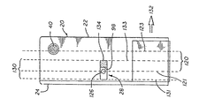
次に図4、図5、図6を参照して、本発明による搭載されているインク槽補充システム100のさらなる部品および動作を次に説明する。当業者には公知のように、キャリッジの位置は、エンコーダ・バー16を位置基準として組み込んだ光学的エンコーダ102を含む位置監視システムによって決定される。この位置モニタによって、いかなる時点におけるキャリッジ12の位置も、プリンタ(図示せず)において実施されたインク補充制御装置104が知る。制御装置はさらに、プロセッサ106、メモリ108、およびクロック110を含む。これから明白になるように、制御装置の部品は単一のICチップ上で実施することができ、こういったシステムの要素の実施の詳細は、当業者が用いる公知の方法の1つであってもよい。現存するプリンタのキャリッジ位置モニタを用いれば、コストが下がる結果になる。
【0025】
インク補充制御装置104は、搭載されているインク槽のカートリッジ20内のインクの補充を制御し、カートリッジ内のインクが印字動作においてプリントヘッド26によって引き出されてあらかじめ選択した量より少ない体積になるとインク補充を行う。補充は、搭載されていない供給インク60からインク供給ライン38およびコネクタの針44内に組み込まれた針コネクタ毛管を通り搭載されている内部インク槽チャンバ内へ、とインクを移動するのに必要な超過圧力を与えることによって行われる。前述した逆止弁の代わりに動作させることができる弁66を用いる場合は、弁のアクチュエータ112を設けて、必要に応じてインク供給ライン38内の弁66を動作して、インク供給ラインを通る液体の伝達を開閉する。搭載されていない供給インクに圧力を与えるポンプ64を動作するために、圧力のアクチュエータ114が設けられている。図示の実施例において、インク補充制御装置104と弁および加圧のアクチュエータの間の適当なインターフェースを、アクチュエータ制御装置116と呼ぶものとする。
【0026】
インクのカートリッジ20の搭載されているインク槽内のインク体積は、インクレベルのインジケータ98の相対的な位置を感知することによって監視される。インクレベルのインジケータは、カートリッジ内の視位置28を貫く視界ラインにおいて見られる、向こう側の見えないインクを充填した内部インク槽インク袋の移動可能な壁96を含む。特に図4を参照して、2つの仮想平面122、124の間の領域によって規定される、仮想インク感知領域120を示す。光源126およびフォトセンサ(photosensor)128が一直線をなして配置されており、カートリッジが光源からフォトセンサへ投じられた光のビームを貫いて移動するときに、カートリッジ20の視位置28を貫く視界ラインに沿って光を投じるようになっている。インク感知領域120は、実際は、光源からフォトセンサへの直線が視位置の開口部30、34を貫いて通る場合のキャリッジ12の位置の範囲を単に示すだけであり、光源からの光は、潜在的に、視位置がインクレベル98によって遮られない場合は、視位置を貫くフォトセンサによって検出することができる。これは、開口部が光源およびフォトセンサとそのように整列する時間の間に、キャリッジ上の単一のとびとびの点がそこを通り過ぎるような、キャリッジの動きの道のいかなる部分と考えることもでき、従って、開口部の幅と等しいまたはそれより狭い距離にわたり、具体的に言うと、その時間の間に光学的エンコーダ102が横切るエンコーダ・バー16の部分として言及される。
【0027】
従って、カートリッジ20のハウジング22に関して移動可能な壁96によって規定されたインクレベル98の位置を感知することができるこのインクレベル感知領域は、常に既知となる、というのも、インクのカートリッジ20、キャリッジ12、および視位置28の間の位置関係は常に、プリントヘッドのキャリッジにおけるカートリッジの固定位置のために既知であるからである。これにより、キャリッジ、従って視位置、がインク感知領域にあるときのみ、インクレベルの感知をすることができる。これから明白になるように、本システムは、キャリッジがインク感知領域になければインクレベルを感知せず、蓋板24または視位置を含む開口部30、34の縁とインクレベル98を識別する必要がないようにしている。これもこれから明白になるように、キャリッジ内の開口部(図示せず)は、キャリッジが光源126からフォトセンサ128への視界ラインをその他の方法で遮るとしても、光が通り抜けるように、視位置に隣接して設けねばならない。
【0028】
上記の他に取り得る方法として、例えばその開口部の幅をキャリッジの動きの方向に関して視位置28の開口部30、34と同じまたはそれよりも狭い幅にすることによって、キャリッジ12は光源126からの光を遮蔽するように働くことができる。従って、光は、キャリッジがある特定のペンに関連するインク感知領域にあるときのみにフォトセンサ128に達することができる。しかし、この後者の場合には、システムが、インクレベルを、視位置28を含む開口部の縁と識別せねばならず、このことにより、キャリッジの動きの向きを考慮に入れねばならない。
【0029】
図示の実施例に戻って、キャリッジ12がインクレベル感知領域内に移動すると、インク補充制御装置104によってインクレベルの位置が求められる。位置は、内部のインク槽67の移動可能な壁の向こう側の見えないインクレベル96が、光源126からフォトセンサ128への視界ラインに沿って投じられる光のビームを遮るときに、感知される。より正確には、プリントヘッドのキャリッジ12の位置は、インクレベル98による遮りのための投じられた光における変化をフォトセンサが検出した時刻において、光学的エンコーダ102が検知する。その時刻におけるインクレベルの位置は、光源126とフォトセンサ128の間の直線の位置に対応することが知られており、その時刻におけるキャリッジの位置はキャリッジ位置モニタの光学的エンコーダおよびエンコーダ・バー16によってわかるので、その時刻について、インクレベル98と搭載されているインク槽のカートリッジ20の相対的位置がわかる。プロセッサ106は、この情報が与えられて、インクレベル98を含む移動可能な壁96の位置とメモリ108内に記憶されているインクレベルのカートリッジのハウジング(ink level cartridge housing)22の間の既知の関数関係から、この情報を、その時刻における搭載されている槽内のインク体積と相関させることができる。この関数関係は、当業者に公知のように、例えば参照用テーブルまたはこの関数に近似する数列、または一連の計算ステップの形式で記憶することができる。
【0030】
さらなる1実施例においては、光学的エンコーダ102およびフォトセンサ128が生成するデータから、システムは単に、キャリッジが光源126とフォトセンサ128の間の視界ラインを通って動くときの、キャリッジ12の動きの向きおよび速度、および、検出されるそれぞれの期間の明暗の持続時間を含む検出される光のパターン、を監視する。キャリッジおよびその上に搭載された例えばカートリッジ17、18、19、20、に対応するパターンの要素はわかり、唯一の変数は、それぞれのカートリッジ内のインクレベル98の位置に対応する属性(attributes)である。このように検出された光のパターンのそれぞれのカートリッジ内のインクの体積との相関は、ここでまた、先に決定され制御装置104のメモリ108内にプログラムされた関数関係に従う。この相関は、ある特定のカートリッジ20が補充を必要とするときを決定するのに用いられ、モニタの取り替え(refilling)に用いられることができる。
【0031】
図示の実施例は、1つの移動可能な壁96を有する槽を用いているが、本発明を対向する両側の2つの移動可能な壁(そしてそれゆえそれらに関連する2つの視位置)を有するインク槽に適用することができることは明白である。本実施例においては、移動可能な壁(図示せず)間の距離が槽内のインクの体積に関係する。2つの壁の相対的位置が、壁が単一の実施例と同様に感知されるが、この場合には、ハウジングに関してではなく2つの壁の互いに関してである。その後、図示の実施例と同様に、壁間の距離と、制御装置内に含まれる体積を関係づける経験的または数学的方法によって前もって決定され記憶されている関数をベースにして、体積が決定される。
【0032】
さらなる他の実施例(図示せず)において、2つの移動可能な壁、および移動可能な壁のうちの1つを見ることができる1つの視位置、を有する槽が設けられる。2つの移動可能な壁は、インク槽を充填するまたは空にするとき、略同一の距離だけ反対方向に移動する。本実施例は、他の点ではすべて、ハウジング22内の1つの移動可能な壁96を有する槽と同じように機能するが、2つの壁が一様に移動しないかもしれず、2つの壁が両方ともハウジング22に関して単一の方向に移動するかもしれないので、インクレベルが視位置内で見られるインクレベルよりも高すぎたり低すぎたりし、生来的に槽内のインク体積を監視できる正確さの程度がより低い。
【0033】
動作において、インク体積は、周期的に、例えばプリンタ10が完全な1ページを印字する毎に1度、監視される。搭載されているインク槽内で必要なインクの最小体積は、例えば、完全な真っ黒にした1ページを印字するのに必要な体積に対応する。こういったパラメータを例として想定して、最小体積に近づくと、補充が開始されるが、補充は以下の2つの形式のうちのどちらでもあり得る。1)「いっぱい」に対応するあらかじめ選択した体積に達するまで充填し、充填の間の感知をより頻繁にすることによる補充、または、2)あらかじめ選択した最小の体積の限度と「いっぱい」の差に対応する単なる設定量、または実際に感知された体積をベースにした他の量、であるあらかじめ決定した体積分の補充。第2の方法であれば、補充しすぎることを緩和するための予備容量、および/または体積が理論的にいっぱいに近づく計算によって出した時間におけるレベルのチェック、を用いることができる。
【0034】
補充インクは、図示の実施例において、インクのカートリッジ内の隔壁40も含む針のコネクタの針44の内腔を含む狭窄した毛管を設けることにより、上述のようにインクのカートリッジ20の搭載されている内部インク槽内に計量されて入る。理解できるように、供給インク60にあらかじめ選択した一定の圧力をかけ、弁66を開いてインクがインク供給ライン38を通って立ち上がり管48および針のコネクタの針44を含む空気タンク46に流入するようにすることで、空気タンクの立ち上がり管内に大気圧より高い圧力を与える。さらに理解できるように、この選択された値のインク供給圧力において、既知の時間内に既知の直径および長さの針44の毛管を既知の体積のインクが通り抜ける。この圧力は、充填速度を低速にし、圧力調整装置72によって内部インク槽82内の負圧が維持されるように選択される。さらに理解できるように、毛管は、例えば印字キャリッジおよび供給ラインの移動や弁66が開くことによって引き起こされる周期的な圧力の急激な上昇が減衰し、毛管を通る流れが制限されて、搭載されているインク槽内の大気圧より低い圧力を維持する圧力調整装置72の機能がいかなる時においても弱まらないような大きさになっている。
【0035】
充填速度を低速にすることにより、上述の充填の間にインク体積を監視することもまた可能になる。この監視は数秒、または、補充の間印字が継続している場合には、あらかじめ選択した印字行数をカウントすることによって規定される期間ごとに行うことができる。クロック110がインク補充制御装置104内に設けられており、1実施例におけるいかなる必要なタイミング機能も果たす。さらなる1実施例において、制御装置が毛管を通る既知の速度を用いて、供給インクが加圧される期間を計ることによって、選択された体積のインクを搭載されている槽82に加えることができる。
【0036】
選択された量のインクを計量して搭載されているインク槽に入れるのに十分な時間が経過すると、および/またはシステムが槽82内にいっぱいの体積のインクを感知すると、圧力のアクチュエータ114およびポンプ64が停止し、弁66が閉じ、または閉じられて、搭載されている供給インクを密封する。このように供給インクを密封することにより、インク補充とインク補充の間の期間にわたって、搭載されている槽内の大気圧より低い圧力が維持される。
【0037】
前述したように、空気タンク46により、インク供給チューブ38を通過するいかなる空気も、空気弁の膜50にぶつかって立ち上がり管48内に蓄積する。供給インクの加圧の間、空気タンク内の圧力によって、この捕らえられた空気が膜を通り空気タンクの蓋板52の開口部54を通ってシステムの外に押し出される。空気弁は、例えば空気を閉め出す液体層57を膜50の上に設けることにより、空気が空気弁を反対向きに通り抜けないように構成されている。かかる液体層は、グリコールまたは通常のプリンタの動作条件の下で蒸発しないその他の物質で形成することができる。または、あるいはかかる液体層を設けることと共同で、一方向逆止弁(ダックビル、バイアスして閉じた(biased-closed)フラッパ弁等)を蓋52に組み込んで、補充の間に空気が立ち上がり管48から押し出されかかる弁を通る間以外はそこを通って空気が逃げないように開口部54を密封する。従って、空気弁50は、搭載されている槽内の大気圧より低い圧力に逆らって真空を保持し、針44の毛管を通ってインクを引き出す結果につながるが、システムは、他の点では、インク供給ライン38内の弁66が閉じていることにより、シールされている。かかる膜の材料は、多数のメーカから商業的に入手可能である。例えば、ゴアテックス(テフロン微小孔材に対するW. L. Gore & Associatesの登録商標)を用いることができる。前述のとおり、ダックビルまたはフラッパ弁等の逆止弁(図示せず)をシステムの膜の外側に付け加えて、システム内の負圧の維持をさらに保証することができ、または膜の代わりにさえすることができる。
【0038】
他の実施例において、所望の量のインクが計量されて搭載されている槽67に入ると、ポンプ64が逆転して、供給ライン38内の圧力が減少して大気圧より低くなる。コネクタの隔壁40が搭載されている槽の一番上の部分に配置されているので、槽67内に導入されたいかなる空気も、コネクタに隣接して集まる。圧力が真空に転じると、集まった空気は針44を通って引き出され空気タンク46に入る、または、供給ライン38を通って例えば供給インク60に結合した搭載されていない空気タンク(図示せず)に行く。
【0039】
次に図6を参照して、インクレベル98の感知の正確さを増すために、光源126は十分小さくするべきであり、さらに、フォトセンサ(図示せず)は感知される光における変化を高い信頼性で検出する、すなわちインクレベル98の同じあらかじめ選択された位置において、好ましくは簡単にするために光源とフォトセンサの間の仮想直線の位置において、一致して「作動」する、ような大きさになっている、ということが理解できる。理解できるように、フォトセンサのこの作動は、視位置28のある部分が光源からフォトセンサへのこの仮想線によって横断されるある瞬間に起こる。実例で説明する目的のために、これは、カートリッジ20がキャリッジ(図示せず)とともに図6に見られるように左から右へ132の方向に動いているとき、線133に対応する前縁が線121と123の間の部分120内にあるときに起こる。前述のとおり、この空間120の幅は、視位置28の幅に対応する、線131と線133の間の幅130に等しい。
【0040】
1実施例において、フォトセンサ128は、キャリッジ12がインクレベル感知領域内にあるときに作動「できるようになる」が、他の時には作動できない、というようにしてもよい。これにより、先に説明したとおり、例えば蓋板24またはハウジング122における第1および第2のスロット30、34の縁134の通過に応じたフォトセンサの作動によって生じるノイズ信号が除去される。
【0041】
図7および図8を参照して、移動可能な壁96が水平方向に向いている他の実施例を示す。ここで、同じ参照番号は前述の実施例における対応する要素を表し、一般的に、上記説明がこのさらなる実施例の説明および動作にも当てはまるということが理解されよう。しかし、この移動可能な壁は垂直に、それゆえキャリッジ12および搭載されているインク槽のカートリッジ20の動きの方向とは直角に移動する。本実施例において、インクレベル98の位置は、垂直方向に向いているとびとびのフォトセンサ(例えば138、139、140)の直線状の光線136で検出することができる。視位置28が移動してインクレベル感知領域120に入ると、一番上のフォトセンサのみが作動し、列の一番下のフォトセンサはインクレベル98の位置に対応して作動される。ここでもまた、図示のインクレベル感知領域120は、視位置28の前縁が図8の左から右へ132の向きに移動する部分に一致する。他の図示のインク感知領域160は、搭載されているインク槽のカートリッジ20の反対方向への移動に一致する。しかし、理解されるように、垂直方向に向いている一連の点(十分小さいセンサで近似させる)とは対照的に、列が幅寸法162を有する場合、視位置28の開口部の幅同様に列の幅を考慮に入れなければならない。
【0042】
または、単一のフォトセンサ(図示せず)を、インクレベル98が選択した最小のインク体積に対応するあらかじめ選択した位置よりも低くなるときに作動するように配置することもできる。こうすると、この選択した最小の体積と「いっぱい」の体積の間の体積の差に等しい量のインクの補充が開始される。第2の単一のフォトセンサ(図示せず)を設けていっぱいになった状態を検出することができる。
【0043】
当業者であれば、本明細書で開示された本発明の好適な実施例から様々の変更をすることができ、保護の範囲は添付の特許請求の範囲の限定によってのみ規定されるよう意図されている、ということを容易に理解するであろう。
【図面の簡単な説明】
【図1】本発明の環境を示す、コンピュータが駆動するプリンタの斜視図である。
【図2】本発明によるプリントヘッドのカートリッジと、接続された搭載されていない供給インクの、斜視図である。
【図3】つぶれることのできるインク槽の構造を含む熱インク・ジェット・プリンタ用のプリントヘッドのインクのカートリッジの分解斜視図である。
【図4】コンピュータが駆動するプリンタにおける、本発明によるインク供給システムを概略的に示す図である。
【図5】一部が立面図である、図3のカートリッジの5−5線縦断面図である。
【図6】図5のカートリッジの立面図である。
【図7】本発明の搭載されたインク槽のプリントヘッドのカートリッジの他の実施例の図8の7−7線断面図である。
【図8】図7のカートリッジの図7の8−8線から見た立面図である。
【符号の説明】
12 ・・・ キャリッジ
28 ・・・ インク視位置
67 ・・・ インク槽
98 ・・・ インクレベル
120 ・・・ インクレベル感知領域
126 ・・・ 光源
128 ・・・ フォトセンサ[0001]
FIELD OF THE INVENTION
The present invention relates generally to ink supply for a printhead of a printer driven by a computer at high speed, such as an ink jet printer or plotter. More specifically, the present invention relates to an ink mounted on a carriage from a stationary supply ink separated from the printer carriage in an ink tank mounted on a printer carriage supplied to a print head mounted on a carriage that draws ink. The present invention relates to an ink supply system characterized by ink replenishment leading to a tank.
[0002]
[Description of related technology]
In an ink jet printer or plotter driven by a computer, the supplied ink is usually held in a tank on the carriage of the print head immediately adjacent to the print head, and the supplied supply ink is supplied to the print head. This tank is usually combined with the print head in a single cartridge. In such printers, for example, this “onboard” ink reservoir is typically maintained at a pressure below atmospheric pressure, ie, negative pressure, so that ink does not leak or “dripping” from the printhead. Yes. Conventionally, various types of ink reservoirs are used, including cartridges of ink reservoirs that can be refilled. This refilling ink reservoir cartridge is a disposable replaceable cartridge mounted on a movable printer carriage and is separated from the mounted ink reservoir, ie “not mounted” “A combination of ink reservoirs. When unmounted supply ink is used, ink is drawn and supplied to the printhead unit or cartridge, which typically incorporates the mounted ink reservoir just mentioned. The ink can be transported from an ink supply tank that is not mounted to a print head unit mounted on a carriage via, for example, a flexible pipe.
[0003]
In particular, one known ink cartridge includes a bag formed of a flexible membrane-like sheet material that is biased away from the two side plates by a spring contained therein. The internal ink tank of the “bag” is used. The spring tends to increase the volume of the bag (and resist contraction) and maintain a pressure below the internal atmospheric pressure. All further information regarding such cartridges is assigned to the assignee of the present application and is hereby incorporated by reference into US Pat. No. 5,280, issued to Fong et al. On January 18, 1994. No. 5,300, US Pat. No. 5,325,119 issued to Fong on June 28, 1994, and US Pat. No. 5 issued to Hunt et al. On October 25, 1994. , 359,353.
[0004]
Omitting disposable ink cartridges, and to the extent possible, waste ink, in view of environmental issues related to waste ink and disposal of ink containers, and further purchase and operating costs for printer and plotter users This is a desirable objective in view of lowering. The printer equipment operator can replenish the supply ink, and the used ink cartridge or the non-mounted ink supply container that can be easily replenished because the frequency of processing the ink does not increase. Is an important step in this direction.
[0005]
There are difficulties that have been encountered with providing such unmounted supply ink and mounted ink reservoirs. In particular, the amount of ink ready to be supplied in the tank of the loaded ink spring bag must be kept within certain limits and at the same time the negative pressure in the bag must be kept. This process is difficult because, in order to prevent the pressure inside the bag from rising to atmospheric pressure, it is necessary to regulate the injection of ink into the tank, This is because the ink volume of the ink must be carefully monitored. One solution to monitoring ink volume is to "count drops", i.e., monitor the amount of ink ejected from the printhead by counting individual ejections of ink. . This drop counting and other known methods tried did not give accurate results.
[0006]
Furthermore, in order to ensure that the printer operates properly, the introduction of air into the print head must be prevented with respect to replenishment of the supplied ink. In addition, the movement of the printhead carriage and, as a result, the flexible conduit between the unloaded supply ink and the loaded reservoir, allows fluctuations in the pressure and delivery speed of the ink being carried. Contamination of the tank in which the air bubbles that occur and pass over the pipeline is also promoted. This situation can occur when air enters the tank in which it is loaded and is drawn into the printhead, or when the internal pressure rises to atmospheric pressure or higher due to such pressure or flow fluctuations and the ink drips from the printhead. In addition, it can jeopardize the proper functioning of the printhead.
[0007]
Recognizing these difficulties, the present invention is directed to providing a system for replenishing an installed ink reservoir at a reasonable low cost, thereby reducing waste. More specifically, it is intended to be used with a mounted ink tank maintained at a pressure lower than atmospheric pressure, monitoring the ink volume in the mounted tank and controlling that tank as needed. A system is provided that includes replenishing in a controlled manner.
[0008]
Summary of the Invention
Accordingly, the present invention provides an apparatus for sensing the ink level of an ink reservoir mounted on a printer carriage in a computer-driven printer having a printhead carriage movable along the path. The position of the carriage of the print head along the apparatus can be detected by the printer. The ink tank mounted on the carriage includes a rigid outer housing and a movable wall accommodated in the rigid outer housing. An internal reservoir that is movable relative to the rigid outer housing, the internal reservoir defines a variable volume chamber within the rigid external housing, and the rigid external housing has an ink level indicator. Including the movable wall The ink level indicator including an ink viewing position provided by an ink level indicator And the ink viewing position The ink level indicator from outside the rigid outer housing ink Configured to be illuminated by a light beam directed at the viewing position And The position of the ink level indicator is movable with the movable wall, the position of the ink level indicator has a correlation with the volume of ink in the ink tank mounted on the carriage, and the volume of the ink is the ink level. The passage of the ink tank mounted on the carriage, determined from the relative position of the indicator and the rigid outer housing An ink sensing area having a predetermined width in a direction parallel to An ink tank mounted on the carriage together with the carriage pass The ink sensing area and the light beam are Facing across the passage in the ink sensing area; The ink tank is Feeling Intellectual domain Passing and when Reaching the ink viewing position An optical sensor for detecting the light beam, ,in front The detected light changes when the light beam is blocked by the ink level indicator at the ink viewing position of the ink tank mounted on the carriage, and the position of the ink level indicator is detected. And the ink level indicator The position of When detected, the rigidity of the current Outside Housing In a direction parallel to the passage Place Place Means for detecting; The position of the detected ink level indicator and the position of the detected rigid housing; Means for comparing the volume of ink Is And a means for comparing that is determinable.
[0009]
In a more detailed aspect, an ink conduit having a flexible ink supply line is disposed between an ink supply container not mounted and the supply ink mounted on the carriage. A structure including pressure and flow restriction and stabilization means is incorporated in the ink replenishment system and is positioned adjacent to the tank mounted on the carriage and controlled flow in the tank mounted on the refilled carriage. The reservoir loaded on the carriage can remain below atmospheric pressure for one refill cycle. This flow restriction and stabilization means may include a constricted fluid conduit, and further includes a needle and septum connector lumen between the ink reservoir mounted on the carriage and the flexible supply line ( inner lumen). Further, an air tank including a riser and a one-way vent is incorporated in the conduit to prevent air from reaching the print head. A one-way vent allows air to exit the air tank, but prevents ink escape and entry of air and other impurities.
[0010]
In an even more detailed aspect, the ink level can be sensed using a light source and a photoelectric sensor. The opening in the ink reservoir housing provides a single field of view through which the ink level can be observed through the cartridge and including the movable wall of the ink reservoir in the internal spring bag. The opening is sized so that the ink level at various positions can be observed. When mounted on the carriage of the printer, the ink level is determined by the change in the light emitted by the light source and received by the photoelectric sensor. Can be sensed. As the carriage moves past the photoelectric sensor, the level of ink located in the direct line from the light source to the sensor is detected, the change in light senses the carriage position, and the cartridge position is determined by the optical encoder bar. And based on the carriage position monitor with reference to the associated optical sensors. Since the relative position of each of these elements is thus sensed, the ink volume is determined according to the known relationship of the ink level position with respect to the rest of the cartridge.
[0011]
DETAILED DESCRIPTION OF THE INVENTION
The drawings are all given by way of example and not limitation, and with reference to FIG. 1 there is shown an ink-jet type computer in which printing is performed by a very small jet of ink as known to those skilled in the art. The driving
[0012]
FIG. 2 shows an
[0013]
Referring to both FIG. 2 and FIG. 3, the
[0014]
An
[0015]
In a further embodiment not shown, a one-way valve such as a conventional duckbill or flapper check valve or a combination of a float valve and a check valve replaces the membrane air valve.
[0016]
The flexible
[0017]
With particular reference to FIG. 2, the unloaded
[0018]
An inlet pipe (not shown) connected to the
[0019]
As will become apparent, the flow of ink into the mounted
[0020]
Next, referring to FIG. 3 and FIG. 5, it is contained in a part of the housing, is formed of a relatively hard inert plastic resin, and serves as a frame for the
[0021]
The
[0022]
The flexible film-
[0023]
The
[0024]
With reference to FIGS. 4, 5, and 6, further components and operation of the installed ink
[0025]
The ink
[0026]
The ink volume within the ink reservoir in which the
[0027]
Thus, this ink level sensing area, which can sense the position of the
[0028]
As another possible method, for example, the width of the opening may be the same as or narrower than the
[0029]
Returning to the illustrated embodiment, when the
[0030]
In a further embodiment, from the data generated by
[0031]
Although the illustrated embodiment uses a vat with one
[0032]
In yet another embodiment (not shown), a bath having two movable walls and a viewing position where one of the movable walls can be seen is provided. The two movable walls move in opposite directions by approximately the same distance when filling or emptying the ink reservoir. This embodiment all works in the same way as a vat with one
[0033]
In operation, the ink volume is monitored periodically, for example once every time the
[0034]
In the illustrated embodiment, the refill ink is mounted on the
[0035]
By lowering the filling speed, it is also possible to monitor the ink volume during the filling described above. This monitoring can be performed for several seconds or every period defined by counting the number of print lines selected in advance when printing continues during replenishment. A
[0036]
When sufficient time has elapsed to meter a selected amount of ink into a loaded ink reservoir and / or when the system senses a full volume of ink in
[0037]
As described above, any air passing through the
[0038]
In another embodiment, when the desired amount of ink is metered into the
[0039]
Referring now to FIG. 6, the
[0040]
In one embodiment, the
[0041]
7 and 8, another embodiment is shown in which the
[0042]
Alternatively, a single photosensor (not shown) can be arranged to operate when the
[0043]
Those skilled in the art can make various modifications to the preferred embodiments of the present invention disclosed herein, and the scope of protection is intended to be defined only by the limitations of the appended claims. You will easily understand that.
[Brief description of the drawings]
FIG. 1 is a perspective view of a computer-driven printer showing the environment of the present invention.
FIG. 2 is a perspective view of a printhead cartridge according to the present invention and a connected ink supply that is not mounted.
FIG. 3 is an exploded perspective view of a printhead ink cartridge for a thermal ink jet printer including a collapsible ink reservoir structure.
FIG. 4 is a diagram schematically illustrating an ink supply system according to the present invention in a printer driven by a computer.
5 is a longitudinal cross-sectional view of the cartridge of FIG. 3, taken partially along elevation, taken along line 5-5.
6 is an elevational view of the cartridge of FIG.
7 is a cross-sectional view taken along the line 7-7 in FIG. 8 of another embodiment of the print head cartridge of the ink tank according to the present invention.
8 is an elevational view of the cartridge of FIG. 7 as viewed from line 8-8 in FIG.
[Explanation of symbols]
12 ・ ・ ・ Carriage
28: Ink viewing position
67 ・ ・ ・ Ink tank
98 ・ ・ ・ Ink level
120 ... Ink level detection area
126 ・ ・ ・ Light source
128 ・ ・ ・ Photosensor
Claims (14)
前記キャリッジに搭載されたインク槽は、剛性の外部ハウジングと、前記剛性の外部ハウジング内に収納される可動壁を含み、前記剛性の外部ハウジングに対して移動可能である内部槽とを有し、
前記内部槽は前記剛性の外部ハウジング内に可変体積室を確定し、
前記剛性の外部ハウジングはインクレベル表示が前記可動壁を含むインクレベルインジケータによって与えられるところのインク視位置を含み、
前記インクレベルインジケータと前記インク視位置とは、前記インクレベルインジケータが前記剛性の外部ハウジングの外側から前記インク視位置へ向けられた光ビームによって照らされるように構成され、
前記インクレベルインジケータの位置は前記可動壁とともに移動可能であり、前記インクレベルインジケータの位置は前記キャリッジに搭載されたインク槽内のインクの体積に対する相関を有し、前記インクの体積が前記インクレベルインジケータ及び前記剛性の外部ハウジングの相対位置から判定され、
前記キャリッジに搭載されたインク槽の前記通路と平行な方向に所定の幅を有するインク感知領域であって、前記キャリッジに搭載されたインク槽が前記キャリッジとともに通過するインク感知領域と、
前記光ビームは、前記インク感知領域内で前記通路を横切る向きを向いており、前記インク槽が前記インク感知領域を通過するとき前記インク視位置に到達し、
前記光ビームを検出する光センサであって、前記検出される光は前記キャリッジに搭載されたインク槽の前記インク視位置において前記インクレベルインジケータによって前記光ビームが遮蔽されることで変化し、前記インクレベルインジケータの位置が検出される、光センサと、
前記インクレベルインジケータの位置が検出された時点で、このときの前記剛性の外部ハウジングの前記通路に平行な方向の位置を検出する手段と、
前記検出されたインクレベルインジケータの位置と前記検出された剛性のハウジングの位置とを比較する手段であって、これによりインクの体積が判定可能である、比較する手段と、
を備えることを特徴とするインクレベルを感知する装置。In a computer driven printer having a printhead carriage movable along a path, a device for sensing the ink level of an ink reservoir mounted on the printer carriage, wherein the printhead along the path In the apparatus, the position of the carriage is detectable by the printer,
The ink tank mounted on the carriage has a rigid outer housing and an inner tank that includes a movable wall accommodated in the rigid outer housing and is movable with respect to the rigid outer housing.
The inner tank defines a variable volume chamber within the rigid outer housing;
The rigid outer housing includes an ink viewing position where an ink level indication is provided by an ink level indicator including the movable wall ;
The ink level indicator and the ink viewing position are configured such that the ink level indicator is illuminated by a light beam directed from outside the rigid outer housing to the ink viewing position ;
The position of the ink level indicator is movable with the movable wall, the position of the ink level indicator has a correlation with the volume of ink in the ink tank mounted on the carriage, and the volume of the ink is the ink level. Determined from the relative position of the indicator and the rigid outer housing;
An ink sensing area having a predetermined width in a direction parallel to the passage of the ink tank mounted on the carriage, and an ink sensing area through which the ink tank mounted on the carriage passes together with the carriage;
It said light beam is oriented to a direction transverse to said passage in said ink sensing region, reaches the ink viewing location when said ink tank passes through the in-click feeling known region,
The optical sensor for detecting the light beam, the light is pre-Symbol detection is changed by the light beam is blocked by the ink level indicator in said ink view position of the ink tank mounted on the carriage, A light sensor for detecting a position of the ink level indicator;
When the position of the ink level indicator is detected, it means for detecting a position in a direction parallel to the path of the outer housing of the stiffness of the case,
And means for comparing the position of the housing of the detected position and the detected rigidity of the ink level indicator, thereby the volume of the ink can be fixed determine, means for comparing,
A device for sensing ink levels, comprising:
前記キャリッジおよび前記インク槽の位置を感知するエンコーダをさらに備え、
前記可動壁が前記光ビームを遮る点における、前記エンコーダによって感知された前記インク槽の位置および前記フォトセンサによって検出された前記可動壁の位置よりインクレベルを決定することを特徴とする、請求項1又は2に記載のインクレベルを感知する装置。 The photosensor is a single photosensor;
Further comprising the carriage and encoder for sensing the position of said ink reservoir,
At the point where the movable wall intercepts the light beam, and determining the ink level from the position of the detected movable wall by position and the photo sensor of the ink tank sensed by the encoder, Apparatus for sensing ink levels according to claim 1 or 2.
前記インク槽内のインクの体積を、前記搭載されていない供給インク槽から、前記インク槽内の感知されたインクレベルをベースにして補充することを特徴とする、請求項1に記載のインクレベルを感知する装置。Comprising a supply of ink tank is not mounted on the movable said a carriage,
The ink level according to claim 1, wherein the ink volume in the ink tank is replenished from the non-mounted supply ink tank based on the sensed ink level in the ink tank. A device that senses
前記インク槽と前記搭載されていない供給インク槽の間に圧力差を設けることで、インクが前記インク供給管路を通り前記搭載されていない供給インク槽から前記インク槽に流れるようにする手段と、
を備えることを特徴とする、請求項6に記載のインクレベルを感知する装置。An ink supply pipe connecting the supply ink tank not mounted and the ink tank;
Means for providing a pressure difference between the ink tank and the non-mounted supply ink tank so that ink flows from the non-mounted supply ink tank to the ink tank through the ink supply line; ,
An apparatus for sensing ink levels according to claim 6, comprising:
前記立ち上がり管内に設けられ、空気が通って前記管路から出ることができるがインクが逃げることは防止されるように構成された通気孔と、
を備えることを特徴とする、請求項7に記載のインクレベルを感知する装置。A riser tube provided in the conduit and configured to be trapped before the air in the conduit enters the ink reservoir;
A vent provided in the riser and configured to prevent air from escaping but allowing air to exit the conduit;
An apparatus for sensing ink levels according to claim 7, comprising:
それぞれのページが印字される毎に、前記インク槽内のインクの体積を感知することを特徴とする、請求項6から請求項11のいずれかに記載のインクレベルを感知する装置。The ink tank has a capacity of an ink volume that is at least as large as a volume necessary for printing one page covered with ink;
The apparatus for sensing an ink level according to any one of claims 6 to 11, wherein the ink volume in the ink tank is sensed each time each page is printed.
空気を前記タンク内に蓄積することによって空気が前記インク槽に入ることを防止し、空気は前記一方向空気弁を通して前記タンクから押し出されることを特徴とする、請求項6から請求項12のいずれかに記載のインクレベルを感知する装置。An air tank and a one-way air valve provided to be adjacent to the ink tank in the conduit;
13. Any of claims 6-12, wherein air is prevented from entering the ink reservoir by accumulating air in the tank, and the air is pushed out of the tank through the one-way air valve. A device for sensing ink levels.
Applications Claiming Priority (2)
| Application Number | Priority Date | Filing Date | Title |
|---|---|---|---|
| US08/545,964 US5757390A (en) | 1992-08-12 | 1995-10-20 | Ink volume sensing and replenishing system |
| US545,964 | 1995-10-20 |
Publications (2)
| Publication Number | Publication Date |
|---|---|
| JPH09136435A JPH09136435A (en) | 1997-05-27 |
| JP4290771B2 true JP4290771B2 (en) | 2009-07-08 |
Family
ID=24178269
Family Applications (1)
| Application Number | Title | Priority Date | Filing Date |
|---|---|---|---|
| JP29442096A Expired - Fee Related JP4290771B2 (en) | 1995-10-20 | 1996-10-16 | Ink volume sensing and replenishment system |
Country Status (4)
| Country | Link |
|---|---|
| US (1) | US5757390A (en) |
| EP (1) | EP0769382B1 (en) |
| JP (1) | JP4290771B2 (en) |
| DE (1) | DE69601851T2 (en) |
Families Citing this family (87)
| Publication number | Priority date | Publication date | Assignee | Title |
|---|---|---|---|---|
| US6273560B1 (en) * | 1994-10-31 | 2001-08-14 | Hewlett-Packard Company | Print cartridge coupling and reservoir assembly for use in an inkjet printing system with an off-axis ink supply |
| JP3507261B2 (en) * | 1995-12-26 | 2004-03-15 | キヤノン株式会社 | Liquid supply method for liquid discharge head and liquid discharge recording apparatus |
| US6206512B1 (en) | 1999-01-29 | 2001-03-27 | Hewlett-Packard Company | Replaceable ink delivery tube system for large format printer |
| US6113229A (en) * | 1996-10-07 | 2000-09-05 | Hewlett-Packard Company | Interchangeable fluid interconnect attachment and interface |
| US7188918B2 (en) * | 1997-01-21 | 2007-03-13 | Hewlett-Packard Development Company, L.P. | Ink delivery system adapter |
| JPH10211716A (en) * | 1997-01-29 | 1998-08-11 | Sony Corp | Printer |
| US6076913A (en) * | 1997-03-04 | 2000-06-20 | Hewlett-Packard Company | Optical encoding of printhead service module |
| US7832817B2 (en) * | 1997-07-15 | 2010-11-16 | Silverbrook Research Pty Ltd | Recyclable printing device with tamper protection |
| JPH11138771A (en) * | 1997-11-06 | 1999-05-25 | Brother Ind Ltd | Ink-jet printer |
| US6196651B1 (en) * | 1997-12-22 | 2001-03-06 | Hewlett-Packard Company | Method and apparatus for detecting the end of life of a print cartridge for a thermal ink jet printer |
| US6155664A (en) * | 1998-06-19 | 2000-12-05 | Lexmark International, Inc. | Off-carrier inkjet print supply with memory |
| GB9822875D0 (en) * | 1998-10-21 | 1998-12-16 | Xaar Technology Ltd | Droplet deposition apparatus |
| JP2000334976A (en) * | 1999-05-31 | 2000-12-05 | Canon Inc | Ink jet recorder, ink supplying device and method for supplying ink |
| DE60044020D1 (en) * | 1999-11-05 | 2010-04-29 | Seiko Epson Corp | RECORDING DEVICE OF THE INK JET TYPE AND METHOD OF INK SUPPLYING THE UNDER TANK USING THE SAME DEVICE AND METHOD FOR CONTROLLING THE AMOUNT OF INK OF THE UNDER TANK BY MEANS OF THE SAME DEVICE |
| US6598965B1 (en) * | 1999-11-30 | 2003-07-29 | Hewlett-Packard Company, L.P. | Fixer usage generation technique for inkjet printers |
| US6431670B1 (en) * | 2000-02-14 | 2002-08-13 | Hewlett-Packard Company | Ink level sensing method and apparatus |
| US6243115B1 (en) | 2000-03-09 | 2001-06-05 | Lexmark International, Inc. | Pressurized ink supply and delivery system for an ink jet printer |
| US6328424B1 (en) | 2000-06-13 | 2001-12-11 | Lexmark International, Inc. | Inkjet cartridge with simultaneous electrical and fluid connections |
| JP2002160354A (en) * | 2000-11-28 | 2002-06-04 | Fuji Photo Film Co Ltd | Image recording apparatus and method |
| US6508545B2 (en) * | 2000-12-22 | 2003-01-21 | Hewlett-Packard Company | Apparatus for providing ink to an ink jet print head |
| US6908179B2 (en) * | 2001-04-04 | 2005-06-21 | Eastman Kodak Company | Ink level and negative pressure control in an ink jet printer |
| US6607262B2 (en) | 2001-06-18 | 2003-08-19 | Hewlett-Packard Company | Reserving ink for printer servicing purposes |
| JP2003053946A (en) * | 2001-08-22 | 2003-02-26 | Canon Inc | Imaging apparatus |
| JP3705208B2 (en) * | 2002-01-16 | 2005-10-12 | セイコーエプソン株式会社 | Ink jet recording apparatus control method and ink jet recording apparatus |
| US6962408B2 (en) * | 2002-01-30 | 2005-11-08 | Hewlett-Packard Development Company, L.P. | Printing-fluid container |
| US7744202B2 (en) * | 2002-01-30 | 2010-06-29 | Hewlett-Packard Development Company, L.P. | Printing-fluid container |
| US7452061B2 (en) * | 2002-01-30 | 2008-11-18 | Hewlett-Packard Development Company, L.P. | Method and device for filling a printing-fluid container |
| US7147310B2 (en) * | 2002-01-30 | 2006-12-12 | Hewlett-Packard Development Company, L.P. | Printing-fluid container |
| US6773098B2 (en) * | 2002-09-26 | 2004-08-10 | Eastman Kodak Company | Method of filling ink supply bag for ink cartridge |
| US7063399B2 (en) * | 2003-06-25 | 2006-06-20 | Lexmark International, Inc. | Imaging apparatus and method for facilitating printing |
| US6959985B2 (en) * | 2003-07-31 | 2005-11-01 | Hewlett-Packard Development Company, L.P. | Printing-fluid container |
| US7004564B2 (en) | 2003-07-31 | 2006-02-28 | Hewlett-Packard Development Company, L.P. | Printing-fluid container |
| US7104630B2 (en) * | 2003-07-31 | 2006-09-12 | Hewlett-Packard Development Company, L.P. | Printing-fluid container |
| JP4529405B2 (en) * | 2003-09-30 | 2010-08-25 | ブラザー工業株式会社 | Inkjet recording device |
| US7234787B2 (en) * | 2004-01-08 | 2007-06-26 | Eastman Kodak Company | Liquid level detection method and apparatus |
| US7210771B2 (en) * | 2004-01-08 | 2007-05-01 | Eastman Kodak Company | Ink delivery system with print cartridge, container and reservoir apparatus and method |
| US20050157112A1 (en) | 2004-01-21 | 2005-07-21 | Silverbrook Research Pty Ltd | Inkjet printer cradle with shaped recess for receiving a printer cartridge |
| US7448734B2 (en) | 2004-01-21 | 2008-11-11 | Silverbrook Research Pty Ltd | Inkjet printer cartridge with pagewidth printhead |
| US7188937B2 (en) * | 2004-01-29 | 2007-03-13 | Hewlett-Packard Development Company, L.P. | Printing-fluid venting assembly |
| US7303267B2 (en) * | 2004-04-02 | 2007-12-04 | Kenneth Yuen | Actuator for automatic ink refill system |
| US20060095280A1 (en) * | 2004-11-03 | 2006-05-04 | Lexmark International, Inc. | Method and apparatus for paying for printing materials in a printer over the usage time of a printer cartridge |
| JP2007007902A (en) * | 2005-06-28 | 2007-01-18 | Fujifilm Holdings Corp | Ink tank and inkjet recorder |
| US7475971B2 (en) * | 2005-12-02 | 2009-01-13 | Xerox Corporation | Ink delivery system |
| JP4872336B2 (en) * | 2005-12-19 | 2012-02-08 | ブラザー工業株式会社 | Inkjet recording device |
| US8967044B2 (en) * | 2006-02-21 | 2015-03-03 | R.R. Donnelley & Sons, Inc. | Apparatus for applying gating agents to a substrate and image generation kit |
| US7419234B2 (en) * | 2006-10-27 | 2008-09-02 | Static Control Components, Inc. | Method and apparatus for spoofing imaging devices |
| US8272704B2 (en) | 2008-05-22 | 2012-09-25 | Zipher Limited | Ink containment system and ink level sensing system for an inkjet cartridge |
| US8091993B2 (en) * | 2008-05-22 | 2012-01-10 | Videojet Technologies Inc. | Ink containment system and ink level sensing system for an inkjet cartridge |
| JP5239899B2 (en) * | 2008-07-29 | 2013-07-17 | 株式会社リコー | Image forming apparatus |
| US8419157B2 (en) * | 2010-02-26 | 2013-04-16 | Palo Alto Research Center Incorporated | Apparatus for controlled freezing of melted solid ink in a solid ink printer |
| JP2011201067A (en) * | 2010-03-24 | 2011-10-13 | Brother Industries Ltd | Set of cartridges and printer |
| JP5565029B2 (en) * | 2010-03-29 | 2014-08-06 | セイコーエプソン株式会社 | Liquid container and liquid consuming device |
| US8303098B2 (en) * | 2010-05-07 | 2012-11-06 | Xerox Corporation | High flow ink delivery system |
| US8506063B2 (en) | 2011-02-07 | 2013-08-13 | Palo Alto Research Center Incorporated | Coordination of pressure and temperature during ink phase change |
| US8556372B2 (en) | 2011-02-07 | 2013-10-15 | Palo Alto Research Center Incorporated | Cooling rate and thermal gradient control to reduce bubbles and voids in phase change ink |
| US8562117B2 (en) | 2011-02-07 | 2013-10-22 | Palo Alto Research Center Incorporated | Pressure pulses to reduce bubbles and voids in phase change ink |
| US11809100B2 (en) | 2012-03-05 | 2023-11-07 | Landa Corporation Ltd. | Intermediate transfer members for use with indirect printing systems and protonatable intermediate transfer members for use with indirect printing systems |
| US20130242010A1 (en) * | 2012-03-16 | 2013-09-19 | Brian J. Kwarta | Method for venting air with a membrane |
| US20130242008A1 (en) * | 2012-03-16 | 2013-09-19 | Brian J. Kwarta | Ink supply having membrane for venting air |
| TWI600550B (en) * | 2012-07-09 | 2017-10-01 | 滿捷特科技公司 | Printer having ink delivery system with air compliance chamber |
| MY166230A (en) * | 2012-08-10 | 2018-06-22 | Seiko Epson Corp | Liquid container, liquid consuming apparatus, liquid supply system and liquid container unit |
| US9180674B2 (en) | 2013-02-08 | 2015-11-10 | R.R. Donnelley & Sons Company | System and method for supplying ink to an inkjet cartridge |
| JP6519225B2 (en) | 2015-02-25 | 2019-05-29 | セイコーエプソン株式会社 | Dummy member and liquid ejecting apparatus |
| WO2017121759A1 (en) * | 2016-01-11 | 2017-07-20 | OCE Holding B.V. | Ink supply system, print-head and printing system |
| WO2017196839A1 (en) | 2016-05-09 | 2017-11-16 | R.R. Donnelley & Sons Company | System and method for supplying ink to an inkjet printhead |
| GB201609463D0 (en) | 2016-05-30 | 2016-07-13 | Landa Labs 2012 Ltd | Method of manufacturing a multi-layer article |
| JP7059577B2 (en) * | 2017-11-14 | 2022-04-26 | セイコーエプソン株式会社 | Liquid tank |
| JP7130979B2 (en) * | 2018-02-21 | 2022-09-06 | セイコーエプソン株式会社 | Liquid storage container and recording device |
| CN117885446A (en) | 2018-06-26 | 2024-04-16 | 兰达公司 | Intermediate transfer member for digital printing system |
| JP7246496B2 (en) | 2018-10-08 | 2023-03-27 | ランダ コーポレイション リミテッド | Friction reduction means for printing systems and methods |
| JP7172624B2 (en) * | 2019-01-16 | 2022-11-16 | セイコーエプソン株式会社 | liquid injector |
| JP7305973B2 (en) | 2019-02-12 | 2023-07-11 | セイコーエプソン株式会社 | printer |
| JP7255217B2 (en) | 2019-02-12 | 2023-04-11 | セイコーエプソン株式会社 | printer |
| JP7211133B2 (en) | 2019-02-12 | 2023-01-24 | セイコーエプソン株式会社 | Printing device production method |
| JP7322419B2 (en) | 2019-02-12 | 2023-08-08 | セイコーエプソン株式会社 | printer |
| JP7298173B2 (en) | 2019-02-12 | 2023-06-27 | セイコーエプソン株式会社 | printer |
| JP2020128056A (en) | 2019-02-12 | 2020-08-27 | セイコーエプソン株式会社 | Printing device |
| JP7247625B2 (en) * | 2019-02-12 | 2023-03-29 | セイコーエプソン株式会社 | Electronics |
| US20220274411A1 (en) * | 2019-03-31 | 2022-09-01 | Landa Corporation Ltd. | Systems and methods for preventing or minimizing printing defects in printing processes |
| JP7400260B2 (en) | 2019-08-20 | 2023-12-19 | セイコーエプソン株式会社 | printing device |
| JP7404707B2 (en) | 2019-08-20 | 2023-12-26 | セイコーエプソン株式会社 | printing device |
| JP7334535B2 (en) | 2019-08-20 | 2023-08-29 | セイコーエプソン株式会社 | printer |
| JP7326988B2 (en) | 2019-08-20 | 2023-08-16 | セイコーエプソン株式会社 | printer |
| JP2023505035A (en) | 2019-11-25 | 2023-02-08 | ランダ コーポレイション リミテッド | Ink drying in digital printing using infrared radiation absorbed by particles embedded inside the ITM |
| JP7452132B2 (en) | 2020-03-17 | 2024-03-19 | セイコーエプソン株式会社 | printing device |
| JP7452133B2 (en) | 2020-03-17 | 2024-03-19 | セイコーエプソン株式会社 | printing device |
| JP2021146534A (en) | 2020-03-17 | 2021-09-27 | セイコーエプソン株式会社 | Printing device |
Family Cites Families (15)
| Publication number | Priority date | Publication date | Assignee | Title |
|---|---|---|---|---|
| US4301459A (en) * | 1978-11-16 | 1981-11-17 | Ricoh Company, Ltd. | Ink ejection apparatus comprising entrained air removal means |
| GB2063175B (en) * | 1979-11-06 | 1984-02-15 | Shinshu Seiki Kk | Ink jet printer |
| US4604633A (en) * | 1982-12-08 | 1986-08-05 | Konishiroku Photo Industry Co., Ltd | Ink-jet recording apparatus |
| JPS59194855A (en) * | 1983-04-19 | 1984-11-05 | Canon Inc | Detector for residual ink |
| JPS6032667A (en) * | 1983-08-02 | 1985-02-19 | Canon Inc | Ink remainder detector |
| DE3408302A1 (en) * | 1984-03-07 | 1985-09-12 | Olympia Werke Ag, 2940 Wilhelmshaven | Measuring device for the ink remaining in a flexible ink bag in ink printers |
| JPS6186265A (en) * | 1984-10-04 | 1986-05-01 | Ricoh Co Ltd | Integral ink cartridge type head with ink run-out detector |
| JPS6221549A (en) * | 1985-07-23 | 1987-01-29 | Ricoh Co Ltd | Sensor for residual ink amount in ink cartridge |
| JPS62152859A (en) * | 1985-12-27 | 1987-07-07 | Canon Inc | Recorder |
| JPS62236747A (en) * | 1986-04-08 | 1987-10-16 | Canon Inc | Ink jet printer |
| US4771295B1 (en) * | 1986-07-01 | 1995-08-01 | Hewlett Packard Co | Thermal ink jet pen body construction having improved ink storage and feed capability |
| JPH05169679A (en) * | 1991-12-20 | 1993-07-09 | Ricoh Co Ltd | Residual ink amount detection device |
| JP3167789B2 (en) * | 1992-06-03 | 2001-05-21 | キヤノン株式会社 | INK JET RECORDING APPARATUS AND INK REMAINING LOW DETECTION METHOD |
| JP3143539B2 (en) * | 1993-02-03 | 2001-03-07 | キヤノン株式会社 | Ink remaining amount detecting method and apparatus, and ink jet recording apparatus |
| US5369429A (en) * | 1993-10-20 | 1994-11-29 | Lasermaster Corporation | Continuous ink refill system for disposable ink jet cartridges having a predetermined ink capacity |
-
1995
- 1995-10-20 US US08/545,964 patent/US5757390A/en not_active Expired - Lifetime
-
1996
- 1996-09-04 DE DE69601851T patent/DE69601851T2/en not_active Expired - Lifetime
- 1996-09-04 EP EP96306412A patent/EP0769382B1/en not_active Expired - Lifetime
- 1996-10-16 JP JP29442096A patent/JP4290771B2/en not_active Expired - Fee Related
Also Published As
| Publication number | Publication date |
|---|---|
| JPH09136435A (en) | 1997-05-27 |
| DE69601851T2 (en) | 1999-07-29 |
| US5757390A (en) | 1998-05-26 |
| DE69601851D1 (en) | 1999-04-29 |
| EP0769382B1 (en) | 1999-03-24 |
| EP0769382A1 (en) | 1997-04-23 |
Similar Documents
| Publication | Publication Date | Title |
|---|---|---|
| JP4290771B2 (en) | Ink volume sensing and replenishment system | |
| US5754207A (en) | Volume indicating ink reservoir cartridge system | |
| EP1142713B9 (en) | Inkjet type recording device and method of supplying ink to sub-tank by the same device, and method of checking amount of ink supplied to sub-tank by the same device | |
| EP1379390B1 (en) | Ink level and negative pressure control in an ink jet printer | |
| EP2285579B1 (en) | An ink containment system and ink level sensing system for an inkjet cartridge | |
| US4074284A (en) | Ink supply system and print head | |
| US6866355B2 (en) | Ink jet recording apparatus, and method of supplying ink to sub-tank of the ink jet recording apparatus | |
| US4551734A (en) | Ink cartridge with ink level sensor | |
| US6378971B1 (en) | Ink-jet recording apparatus | |
| US8454146B2 (en) | Ink containment system and ink level sensing system for an inkjet cartridge | |
| US6676237B2 (en) | Ink jet recording apparatus and method of correcting calculation of ink amount consumed therein | |
| JP3451150B2 (en) | Ink replenishment method and apparatus | |
| US8550608B2 (en) | Ink cartridge and inkjet recording apparatus using the same | |
| US6302503B1 (en) | Inkjet ink level detection | |
| KR100532298B1 (en) | Ink container configured for use with a printing device having an out-of-ink sensing system | |
| EP0953450B1 (en) | Inkjet ink level detection | |
| EP1812239B1 (en) | Leak detection structure | |
| JP3462413B2 (en) | Ink jet recording device | |
| JPH0479304B2 (en) |
Legal Events
| Date | Code | Title | Description |
|---|---|---|---|
| A977 | Report on retrieval |
Free format text: JAPANESE INTERMEDIATE CODE: A971007 Effective date: 20060927 |
|
| A131 | Notification of reasons for refusal |
Free format text: JAPANESE INTERMEDIATE CODE: A131 Effective date: 20061017 |
|
| A601 | Written request for extension of time |
Free format text: JAPANESE INTERMEDIATE CODE: A601 Effective date: 20070111 |
|
| A602 | Written permission of extension of time |
Free format text: JAPANESE INTERMEDIATE CODE: A602 Effective date: 20070117 |
|
| A521 | Written amendment |
Free format text: JAPANESE INTERMEDIATE CODE: A523 Effective date: 20070416 |
|
| A131 | Notification of reasons for refusal |
Free format text: JAPANESE INTERMEDIATE CODE: A131 Effective date: 20081014 |
|
| A521 | Written amendment |
Free format text: JAPANESE INTERMEDIATE CODE: A523 Effective date: 20090109 |
|
| TRDD | Decision of grant or rejection written | ||
| A01 | Written decision to grant a patent or to grant a registration (utility model) |
Free format text: JAPANESE INTERMEDIATE CODE: A01 Effective date: 20090324 |
|
| A01 | Written decision to grant a patent or to grant a registration (utility model) |
Free format text: JAPANESE INTERMEDIATE CODE: A01 |
|
| A61 | First payment of annual fees (during grant procedure) |
Free format text: JAPANESE INTERMEDIATE CODE: A61 Effective date: 20090402 |
|
| R150 | Certificate of patent or registration of utility model |
Free format text: JAPANESE INTERMEDIATE CODE: R150 |
|
| FPAY | Renewal fee payment (event date is renewal date of database) |
Free format text: PAYMENT UNTIL: 20120410 Year of fee payment: 3 |
|
| FPAY | Renewal fee payment (event date is renewal date of database) |
Free format text: PAYMENT UNTIL: 20120410 Year of fee payment: 3 |
|
| FPAY | Renewal fee payment (event date is renewal date of database) |
Free format text: PAYMENT UNTIL: 20130410 Year of fee payment: 4 |
|
| LAPS | Cancellation because of no payment of annual fees |