EP0769382B1 - Method and device for detecting the ink level in a cartridge - Google Patents
Method and device for detecting the ink level in a cartridge Download PDFInfo
- Publication number
- EP0769382B1 EP0769382B1 EP96306412A EP96306412A EP0769382B1 EP 0769382 B1 EP0769382 B1 EP 0769382B1 EP 96306412 A EP96306412 A EP 96306412A EP 96306412 A EP96306412 A EP 96306412A EP 0769382 B1 EP0769382 B1 EP 0769382B1
- Authority
- EP
- European Patent Office
- Prior art keywords
- ink
- carriage
- reservoir
- borne
- providing
- Prior art date
- Legal status (The legal status is an assumption and is not a legal conclusion. Google has not performed a legal analysis and makes no representation as to the accuracy of the status listed.)
- Expired - Lifetime
Links
- 238000000034 method Methods 0.000 title claims description 25
- 239000012528 membrane Substances 0.000 claims description 14
- 230000033001 locomotion Effects 0.000 claims description 10
- 239000012530 fluid Substances 0.000 claims description 5
- 238000004891 communication Methods 0.000 claims description 3
- 230000000670 limiting effect Effects 0.000 claims description 3
- 230000000087 stabilizing effect Effects 0.000 claims 1
- 230000006870 function Effects 0.000 description 8
- 230000003287 optical effect Effects 0.000 description 8
- 238000012544 monitoring process Methods 0.000 description 6
- 239000007788 liquid Substances 0.000 description 5
- LYCAIKOWRPUZTN-UHFFFAOYSA-N Ethylene glycol Chemical compound OCCO LYCAIKOWRPUZTN-UHFFFAOYSA-N 0.000 description 4
- 239000000463 material Substances 0.000 description 4
- 239000002699 waste material Substances 0.000 description 4
- 241000405070 Percophidae Species 0.000 description 3
- 238000007789 sealing Methods 0.000 description 3
- 230000002238 attenuated effect Effects 0.000 description 2
- 238000001514 detection method Methods 0.000 description 2
- 238000004836 empirical method Methods 0.000 description 2
- WGCNASOHLSPBMP-UHFFFAOYSA-N hydroxyacetaldehyde Natural products OCC=O WGCNASOHLSPBMP-UHFFFAOYSA-N 0.000 description 2
- 239000012535 impurity Substances 0.000 description 2
- 230000002093 peripheral effect Effects 0.000 description 2
- 239000000088 plastic resin Substances 0.000 description 2
- 230000001105 regulatory effect Effects 0.000 description 2
- 230000006641 stabilisation Effects 0.000 description 2
- 238000011105 stabilization Methods 0.000 description 2
- 229920000544 Gore-Tex Polymers 0.000 description 1
- 239000004809 Teflon Substances 0.000 description 1
- 229920006362 Teflon® Polymers 0.000 description 1
- 208000003443 Unconsciousness Diseases 0.000 description 1
- 238000013459 approach Methods 0.000 description 1
- 238000004364 calculation method Methods 0.000 description 1
- 239000002131 composite material Substances 0.000 description 1
- 230000006835 compression Effects 0.000 description 1
- 238000007906 compression Methods 0.000 description 1
- 230000001010 compromised effect Effects 0.000 description 1
- 238000011109 contamination Methods 0.000 description 1
- 230000001276 controlling effect Effects 0.000 description 1
- 238000005336 cracking Methods 0.000 description 1
- 230000026058 directional locomotion Effects 0.000 description 1
- 230000000694 effects Effects 0.000 description 1
- 229920001971 elastomer Polymers 0.000 description 1
- 239000000806 elastomer Substances 0.000 description 1
- 239000013536 elastomeric material Substances 0.000 description 1
- 230000007613 environmental effect Effects 0.000 description 1
- 230000008595 infiltration Effects 0.000 description 1
- 238000001764 infiltration Methods 0.000 description 1
- 238000001802 infusion Methods 0.000 description 1
- 238000003780 insertion Methods 0.000 description 1
- 230000037431 insertion Effects 0.000 description 1
- 238000012423 maintenance Methods 0.000 description 1
- 238000012067 mathematical method Methods 0.000 description 1
- 238000012986 modification Methods 0.000 description 1
- 230000004048 modification Effects 0.000 description 1
- 230000000737 periodic effect Effects 0.000 description 1
- 239000004033 plastic Substances 0.000 description 1
- 230000002829 reductive effect Effects 0.000 description 1
- 230000002441 reversible effect Effects 0.000 description 1
- 230000000630 rising effect Effects 0.000 description 1
- 229910001220 stainless steel Inorganic materials 0.000 description 1
- 239000010935 stainless steel Substances 0.000 description 1
- 239000000126 substance Substances 0.000 description 1
- 238000003466 welding Methods 0.000 description 1
Images


Classifications
-
- B—PERFORMING OPERATIONS; TRANSPORTING
- B41—PRINTING; LINING MACHINES; TYPEWRITERS; STAMPS
- B41J—TYPEWRITERS; SELECTIVE PRINTING MECHANISMS, i.e. MECHANISMS PRINTING OTHERWISE THAN FROM A FORME; CORRECTION OF TYPOGRAPHICAL ERRORS
- B41J2/00—Typewriters or selective printing mechanisms characterised by the printing or marking process for which they are designed
- B41J2/005—Typewriters or selective printing mechanisms characterised by the printing or marking process for which they are designed characterised by bringing liquid or particles selectively into contact with a printing material
- B41J2/01—Ink jet
- B41J2/17—Ink jet characterised by ink handling
- B41J2/175—Ink supply systems ; Circuit parts therefor
- B41J2/17503—Ink cartridges
- B41J2/17513—Inner structure
-
- B—PERFORMING OPERATIONS; TRANSPORTING
- B41—PRINTING; LINING MACHINES; TYPEWRITERS; STAMPS
- B41J—TYPEWRITERS; SELECTIVE PRINTING MECHANISMS, i.e. MECHANISMS PRINTING OTHERWISE THAN FROM A FORME; CORRECTION OF TYPOGRAPHICAL ERRORS
- B41J2/00—Typewriters or selective printing mechanisms characterised by the printing or marking process for which they are designed
- B41J2/005—Typewriters or selective printing mechanisms characterised by the printing or marking process for which they are designed characterised by bringing liquid or particles selectively into contact with a printing material
- B41J2/01—Ink jet
- B41J2/17—Ink jet characterised by ink handling
- B41J2/175—Ink supply systems ; Circuit parts therefor
- B41J2/17503—Ink cartridges
- B41J2/1752—Mounting within the printer
- B41J2/17523—Ink connection
-
- B—PERFORMING OPERATIONS; TRANSPORTING
- B41—PRINTING; LINING MACHINES; TYPEWRITERS; STAMPS
- B41J—TYPEWRITERS; SELECTIVE PRINTING MECHANISMS, i.e. MECHANISMS PRINTING OTHERWISE THAN FROM A FORME; CORRECTION OF TYPOGRAPHICAL ERRORS
- B41J2/00—Typewriters or selective printing mechanisms characterised by the printing or marking process for which they are designed
- B41J2/005—Typewriters or selective printing mechanisms characterised by the printing or marking process for which they are designed characterised by bringing liquid or particles selectively into contact with a printing material
- B41J2/01—Ink jet
- B41J2/17—Ink jet characterised by ink handling
- B41J2/175—Ink supply systems ; Circuit parts therefor
- B41J2/17503—Ink cartridges
- B41J2/17526—Electrical contacts to the cartridge
-
- B—PERFORMING OPERATIONS; TRANSPORTING
- B41—PRINTING; LINING MACHINES; TYPEWRITERS; STAMPS
- B41J—TYPEWRITERS; SELECTIVE PRINTING MECHANISMS, i.e. MECHANISMS PRINTING OTHERWISE THAN FROM A FORME; CORRECTION OF TYPOGRAPHICAL ERRORS
- B41J2/00—Typewriters or selective printing mechanisms characterised by the printing or marking process for which they are designed
- B41J2/005—Typewriters or selective printing mechanisms characterised by the printing or marking process for which they are designed characterised by bringing liquid or particles selectively into contact with a printing material
- B41J2/01—Ink jet
- B41J2/17—Ink jet characterised by ink handling
- B41J2/175—Ink supply systems ; Circuit parts therefor
- B41J2/17503—Ink cartridges
- B41J2/17536—Protection of cartridges or parts thereof, e.g. tape
-
- B—PERFORMING OPERATIONS; TRANSPORTING
- B41—PRINTING; LINING MACHINES; TYPEWRITERS; STAMPS
- B41J—TYPEWRITERS; SELECTIVE PRINTING MECHANISMS, i.e. MECHANISMS PRINTING OTHERWISE THAN FROM A FORME; CORRECTION OF TYPOGRAPHICAL ERRORS
- B41J2/00—Typewriters or selective printing mechanisms characterised by the printing or marking process for which they are designed
- B41J2/005—Typewriters or selective printing mechanisms characterised by the printing or marking process for which they are designed characterised by bringing liquid or particles selectively into contact with a printing material
- B41J2/01—Ink jet
- B41J2/17—Ink jet characterised by ink handling
- B41J2/175—Ink supply systems ; Circuit parts therefor
- B41J2/17503—Ink cartridges
- B41J2/17553—Outer structure
-
- B—PERFORMING OPERATIONS; TRANSPORTING
- B41—PRINTING; LINING MACHINES; TYPEWRITERS; STAMPS
- B41J—TYPEWRITERS; SELECTIVE PRINTING MECHANISMS, i.e. MECHANISMS PRINTING OTHERWISE THAN FROM A FORME; CORRECTION OF TYPOGRAPHICAL ERRORS
- B41J2/00—Typewriters or selective printing mechanisms characterised by the printing or marking process for which they are designed
- B41J2/005—Typewriters or selective printing mechanisms characterised by the printing or marking process for which they are designed characterised by bringing liquid or particles selectively into contact with a printing material
- B41J2/01—Ink jet
- B41J2/17—Ink jet characterised by ink handling
- B41J2/175—Ink supply systems ; Circuit parts therefor
- B41J2/17503—Ink cartridges
- B41J2/17556—Means for regulating the pressure in the cartridge
-
- B—PERFORMING OPERATIONS; TRANSPORTING
- B41—PRINTING; LINING MACHINES; TYPEWRITERS; STAMPS
- B41J—TYPEWRITERS; SELECTIVE PRINTING MECHANISMS, i.e. MECHANISMS PRINTING OTHERWISE THAN FROM A FORME; CORRECTION OF TYPOGRAPHICAL ERRORS
- B41J2/00—Typewriters or selective printing mechanisms characterised by the printing or marking process for which they are designed
- B41J2/005—Typewriters or selective printing mechanisms characterised by the printing or marking process for which they are designed characterised by bringing liquid or particles selectively into contact with a printing material
- B41J2/01—Ink jet
- B41J2/17—Ink jet characterised by ink handling
- B41J2/175—Ink supply systems ; Circuit parts therefor
- B41J2/17566—Ink level or ink residue control
-
- G—PHYSICS
- G01—MEASURING; TESTING
- G01F—MEASURING VOLUME, VOLUME FLOW, MASS FLOW OR LIQUID LEVEL; METERING BY VOLUME
- G01F23/00—Indicating or measuring liquid level or level of fluent solid material, e.g. indicating in terms of volume or indicating by means of an alarm
- G01F23/22—Indicating or measuring liquid level or level of fluent solid material, e.g. indicating in terms of volume or indicating by means of an alarm by measuring physical variables, other than linear dimensions, pressure or weight, dependent on the level to be measured, e.g. by difference of heat transfer of steam or water
- G01F23/28—Indicating or measuring liquid level or level of fluent solid material, e.g. indicating in terms of volume or indicating by means of an alarm by measuring physical variables, other than linear dimensions, pressure or weight, dependent on the level to be measured, e.g. by difference of heat transfer of steam or water by measuring the variations of parameters of electromagnetic or acoustic waves applied directly to the liquid or fluent solid material
- G01F23/284—Electromagnetic waves
- G01F23/292—Light, e.g. infrared or ultraviolet
- G01F23/2921—Light, e.g. infrared or ultraviolet for discrete levels
-
- B—PERFORMING OPERATIONS; TRANSPORTING
- B41—PRINTING; LINING MACHINES; TYPEWRITERS; STAMPS
- B41J—TYPEWRITERS; SELECTIVE PRINTING MECHANISMS, i.e. MECHANISMS PRINTING OTHERWISE THAN FROM A FORME; CORRECTION OF TYPOGRAPHICAL ERRORS
- B41J2/00—Typewriters or selective printing mechanisms characterised by the printing or marking process for which they are designed
- B41J2/005—Typewriters or selective printing mechanisms characterised by the printing or marking process for which they are designed characterised by bringing liquid or particles selectively into contact with a printing material
- B41J2/01—Ink jet
- B41J2/17—Ink jet characterised by ink handling
- B41J2/175—Ink supply systems ; Circuit parts therefor
- B41J2/17503—Ink cartridges
- B41J2/17513—Inner structure
- B41J2002/17516—Inner structure comprising a collapsible ink holder, e.g. a flexible bag
Definitions
- the present invention relates generally to print head ink supply for high speed computer-driven printers such as ink jet printers and plotters.
- the invention relates more particularly to an ink supply system featuring replenishment of ink in a printer carriage-borne ink reservoir which supplies an ink-drawing carriage-borne print head, such replenishment being conveyed to the carriage-borne ink reservoir from a stationary ink supply off the printer carriage.
- a supply of ink is usually held in a reservoir on the print head carriage immediately adjacent the print head to provide a ready ink supply to the print head.
- This reservoir is usually combined with the print head in a single cartridge.
- this "on-board" ink reservoir is ordinarily maintained at a sub-atmospheric, or negative, pressure, so that ink will not leak or "drool" from the print head.
- Various types of ink reservoirs are conventionally used, including refillable ink reservoir cartridges, which are mounted on the moveable printer carriage, throwaway replaceable cartridges, and combinations of on-board and remote or "off-board” ink reservoirs.
- ink When an off-board ink supply is used ink is drawn to feed a print head unit or cartridge, which usually incorporates the on-board ink reservoir mentioned.
- the ink may be transferred from the off-board ink supply reservoir to the carriage born print head unit via flexible tubing for example.
- certain known ink cartridges employ "spring bag” inner ink reservoir comprising a bag formed of flexible membranous sheet material with two side plates biased apart by a spring contained within.
- the spring tending to increase the volume (and resisting shrinkage) of the bag, maintains a subatmospheric pressure within.
- the present invention is directed to providing, at a reasonably low cost, a method for replenishing an on-board ink reservoir, thereby reducing waste. More particularly, a method is provided which uses an on-board ink reservoir maintained at a sub-atmospheric pressure, and includes monitoring the volume of ink in an on-board reservoir and replenishing it as required in a controlled manner.
- JP-A-59194855 discloses a method of sensing an ink level in a print ink reservoir in a computer-driven printer having a movable print head carriage, comprising the steps of: providing an ink reservoir having a housing and a discontinuity in said housing comprising an ink viewing location where an ink level related to the volume of ink in the ink reservoir can be observed; providing an ink sensing region; providing a beam of light through said ink volume sensing region and directed onto said ink reservoir ink viewing location; providing a sensor for detecting said beam of light; and detecting said beam of light, the light detected being altered by the ink level in said ink reservoir.
- EP-A-573274 also discloses printing apparatus provided with an ink amount detection device.
- the detection device comprises light emitting means, a transparent member and light receiving means.
- the present invention accordingly provides a method of sensing an ink level in a printer carriage-borne ink reservoir in a computer-driven printer having a removable print head carriage movable along a path of said print head carriage, the position of said print head carriage along said path being detectable by said printer, comprising the steps of:
- an ink conduit having a flexible ink supply line portion is disposed between the off-board ink supply and the carriage-borne ink supply.
- Structure comprising a pressure and flow limiting and stabilization means is incorporated in the ink replenishment system, and is disposed adjacent the carriage-borne reservoir, to provide a controlled flow of ink to the carriage-borne reservoir in replenishment, allowing the carriage-borne reservoir to remain at subatmospheric pressure throughout a replenishment cycle.
- This flow limiting and stabilization means can comprise a constricted fluid conduit, and further may be defined by an inner lumen of a needle and septum connector between the carriage borne ink reservoir and the flexible supply line.
- an air accumulator including a riser and one-way air vent, is incorporated in said conduit to prevent air from reaching the print head.
- the one-way air vent allows air to exit the air accumulator but prevents the escape of ink and the entrance of air or other impurities.
- a light source and photoelectric sensor can be employed to sense the ink level. Openings in the ink reservoir housing allow a line of sight through the cartridge in which the ink level, comprising a moveable wall of an inner springbag ink reservoir, is observable. The openings are sized so that a range of positions of the ink level are observable, and when it is mounted on a printer carriage the ink level can be sensed by a change in light emitted by the light source and received by the photoelectric sensor.
- ink level When the carriage moves past the photosensor the ink level is detected as located at a direct line from the light source to the sensor a carriage position by a change in light sensed, and the position of the cartridge is known by virtue of the carriage position monitor with reference to an optical encoder bar and an optical sensor associated therewith. The relative positions of these elements being thus sensed, ink volume is determined according to a known relation of ink level position with respect to the rest of the cartridge.
- a computer-driven printer 10 of the ink jet type wherein printing is performed by extremely small ejections of ink, as is known in the art, includes a carriage 12 slidably supported on supports 14 and 15, and an encoder bar 16 which in conjunction with an optical scanner (not shown) monitors the position of the carriage.
- On-board print head and ink reservoir cartridges 17, 18, 19, and 20, are mounted on the carriage and each contain, for example, color ink (e.g. cyan, magenta, or yellow), or black ink, enabling color printing, black composite, and black ink only printing for example.
- color ink e.g. cyan, magenta, or yellow
- black ink enabling color printing, black composite, and black ink only printing for example.
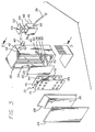
- FIG. 2 An ink cartridge 20 used in the invention is seen in FIG. 2 to comprise a molded rigid plastic resin outer housing 22, having a cover plate 24 intended to be affixed as by cementing or welding to the remainder of the housing.
- the cartridge has an ink discharge aperture in its lowermost end wall (not shown) to which is affixed an electrically-driven print head 26.
- a viewing location 28 is defined by a discontinuity in the housing 22 defined by a first slot 30 in a first side 32, and, as can be seen in FIG. 3, a second slot 34 aligned with the first slot, which allows a line of sight through the housing from the first side to a second, opposite, side 36.
- an ink supply line 38 can be connected to the cartridge 20 via a connector, which in this embodiment comprises a septum 40 formed of an elastomeric material inert with respect to ink and disposed in an opening 42 in the housing 22, and a needle 44 adapted to pierce the septum.
- This connector gives a connection capability free of contamination by air or other impurities.
- a capillary tube (not shown) comprising the interior lumen through the needle also acts as a pressure and flow fluctuation limiter with respect to ink replenishment of the on-board ink reservoir in the cartridge 20 from the flexible supply line 38, and stabilizes the flow at an amount below that which would raise the pressure within the ink reservoir of the cartridge 20 above a preselected subatmospheric pressure.
- the septum may be pre-slit to allow connection of a needle with a relatively blunt point, and the septum can be compressively loaded to effect a seal of any opening formed therethrough by insertion of the needle 44 when it is withdrawn.
- An air accumulator 46 is incorporated in the ink supply line 38 adjacent the connector needle 44, and comprises a riser 48 and an air valve 50 formed of a porous membrane which allows air to pass therethrough, but will not allow ink to pass through.
- a cover plate 52 incorporating a small opening 54 to allow escape of air, closes the top of the riser 48.
- a layer 57 of non-volatile liquid, such as glycol, is disposed over the membrane, preventing air infiltration through the membrane and into the riser even though a vacuum is applied to the interior of the riser 48 of the accumulator 46 lowering the pressure therein to subatmospheric.
- a check valve (not shown), such as a flapper or duck-bill valve biased to a closed position, can be provided.
- the check valve controls the opening 54 on the cover plate to allow escape of air from the riser and prevent air from being drawn into the riser if the pressure in the riser drops below atmospheric. Since it is essential that the riser remain relatively upright for the air accumulator to function properly to trap air bubbles, a ledge 58 is incorporated in the housing 22 to prevent rotation of the air accumulator 46 around a central axis of the needle connector.
- a conventional one-way valve such as a duckbill or a flapper check valve, or a float valve and check valve combinations is substituted for the membrane air valve.
- a ribbed connection portion 56 allows connection of the flexible ink supply line 38 to the riser 48.
- the needle 44 is preferably integral with the riser and formed of a similar ink-inert plastic.
- the ink supply line 38 is formed of an elastomer which does not react with print ink, and allows substantial flexing of the line as required to connect the cartridge moving on the print carriage 12 to the stationary off-board ink supply 60 but resists excessive deformation due to positive and negative pressures within the supply line.
- an off-board ink supply 60 incorporates a sealable container 62 having an actuatable pump 64 configured to pressurize the interior of the container (or evacuate it if required). Adjacent the container a valve 66 controlling ink flow from the container 62 through the ink supply line 38 is provided, which, in conjunction with the pump 64 is employed in controlled replenishment of the on-board ink reservoir in the cartridge 20.
- This valve is a check valve having a cracking pressure less than the pressure to which the ink is pressurized by the pump 64, but greater than that which is required to hold it closed against the negative pressure within the on-board ink reservoir, and thus holds against sufficient vacuum as may be required within the system during normal operation of the printer 10, but opens to allow replenishment when the system is pressurized by the pump 64.
- the valve 66 can be an actuatable valve, for example a stopcock, which can be opened or closed as required.
- the ink supply 60 is simply located vertically lower than the cartridge 20 by a vertical distance sufficient to maintain the negative pressure within the ink reservoir as required for normal printer function. This amount of vacuum usually implicates a vertical differential distance of at least three to seven inches.
- An inlet tube (not shown) connected to the supply line 38 is provided within the ink supply container 62 to draw ink from the bottom of the container and avoid introducing air into the ink supply line 38. Any air that is drawn into the ink supply line, however, is trapped by the air accumulator 46, and is expelled from the system through the air valve 50 when the ink supply container 62 and line are pressurized by actuation of the pump 64.
- an ink-filled flexible bag (not shown) is sealingly coupled to the supply line, for example by a needle and septum connector as described above, and disposed within the container 62, which arrangement allows pressurization of the ink supply without contact between stored ink and air within the container.
- such an ink bag is squeezed by opposing surfaces.
- a syringe pump (not shown) comprising a variable volume chamber connected to the conduit in conjunction with one-way valves disposed in the conduit on each side of the point of connection is used to pressurize the ink in the ink supply conduit.
- ink flow in the replenishment system into the on-board ink reservoir cartridge 20 is stabilized, as well as metered, by the capillary segment comprising inner lumen of the needle 44 of the connector.
- the constricted capillary tube allows only a preselected flow through the connector into the ink cartridge, with a small known and allowable variation, over an range of pressure fluctuations in the ink supply line 38 occasioned by pressurization for replenishment, overlain with pressure fluctuations caused by movement of the print head carriage 12 and consequently the supply line 38.
- the amplitude of pressure and flow fluctuations in the supply line is attenuated and a relatively stable preselected flow rate and fluid pressure results at a distal end of the needle 44.
- This preselected flow rate is chosen so that the on-board reservoir of the cartridge 20 will be filled relatively slowly so that the pressure in the ink reservoir is maintained at subatmospheric, or "negative” pressure during replenishment, even though the ink in the supply container 62 and supply line 38 is under a superatmospheric, or "positive” pressure. Slow filling also allows monitoring during filling to prevent over- or under-filling.
- a negative pressure in the on-board ink reservoir of the illustrated embodiment is created and maintained is discussed below, and it will be appreciated that this negative pressure can be maintained as long as the pressure and flow rate of replenishment ink entering the on-board ink reservoir does not overwhelm its inherent pressure regulating function.
- an inner ink reservoir structure 67 is formed within the housing 22, comprised in part of the housing, formed of a relatively rigid inert plastic resin, acting as a frame and also part of an inner inclosure of the reservoir 67, and a flexible ink bag membranous sheet 68, having a low elasticity and also inert with respect to ink, attached thereto by heat bonding the peripheral edges of the membranous sheet to the inner periphery of the housing.
- An outermost ledge 70 of a series of concentric ledges is provided around the interior of the housing for this purpose.
- the inner ink reservoir structure contains a stainless steel pressure regulator 72 which in turn is comprised of a pair of spaced substantially parallel plates 74, 76 urged apart by a welded spring 78 into engagement with the flexible membranous sheet 68 and a further concentric ledge 80.
- a chamber 82 of variable volume is thus formed within the housing, which chamber is in fluid communication with the connector septum 40 via a channel 84 formed in the housing, and the print head via a further channel 86.
- An entrance to said further channel 86 to the print head is defined by an innermost concentric ledge 88 and a filter 90 supported thereby and attached thereto at the peripheral edges of the filter.
- the lowermost portion of the outer housing 22 (as viewed in FIG. 5) is provided with an ink discharge aperture 92 through which ink is downwardly discharged from the channel 86 leading from the filter 90 to the print head 26.
- the pressure regulator side plates 74, 76 are of generally rectangular configuration with rounded corners to avoid damaging the flexible bag membranous sheet 68.
- One or more openings 94 is provided in each plate to allow ink to flow therethrough to the filter 90 in the assembled ink reservoir.
- the pressure regulator is reversible, facilitating assembly of the cartridge 20 After installing the septum 40 and print head 26, the filter 90, pressure regulator 72, membranous sheet 68, and cover plate 24 are attached in that order.
- the concentric ledges 70, 80, and 88 and stacked component arrangement make the inner ink reservoir very easy to assemble.
- the regulator 72 Prior to or simultaneous with attachment of the membranous sheet 68 to the housing 22, the regulator 72 is placed in position and pre-loaded by collapsing it partially against the spring force such that it is in a prestressed condition inside the inner ink reservoir bag chamber formed by the housing 22 and membranous sheet 68.
- the amount of this pre-stressing is readily controllable by the designer selecting the desired characteristics and amount of compression of the spring 78.
- the flexible membranous sheet 68 and a side plate 74 of the regulator 72 forms a movable wall 96 of the inner ink reservoir, and this moveable wall gradually moves towards the housing 22 as the reservoir is evacuated of ink by the print head 26 in operation.
- the moveable wall is visible along a line of sight through the slots 30, 34 defining the viewing location 28.
- the membranous sheet 68 is sized with enough extra membranous sheet material near the edges of attachment to the outermost concentric ledge 70 of the housing 22 that the wall is freely moveable with the side plate between full and empty positions as best indicated in FIG. 5.
- the pressure regulator 72 constantly biases the movable wall 96 to the furthest position away from the housing 22 allowed by the volume of ink presently in the inner ink reservoir at any instant of time.
- the ink level 98 will obstruct as much of the viewing location as the volume of ink will allow, and the position of this ink level is reliably indicative of the true volume of ink in the inner reservoir according to a readily determined functional relationship between the position of the ink level and the volume of ink remaining in the inner reservoir bag.
- This functional relationship is non-linear, but can be readily ascertained by empirical methods, or calculated, for example by use of computer-aided modeling techniques. Once this functional relationship is known, it can be used to correlate ink level to ink volume in the inner ink reservoir of the cartridge 20.
- the position of the carriage is determined by a position monitoring system including an optical encoder 102 incorporating the encoder bar 16 as the positional reference.
- an ink replenishment controller 104 embodied in the printer (not shown).
- the controller further comprises a processor 106, memory 108, and clock 110.
- components of the controller can be embodied on a single IC chip, and the specifics of implementation of these system elements can be one of the well known ways employed by persons skilled in the art. Use of the existing carriage position monitor of the printer results in lower costs.
- the ink replenishment controller 104 controls replenishment of ink in the on-board ink reservoir cartridge 20, effecting ink replenishment when ink volume in the cartridge is drawn below a pre-selected amount by the print head 26 in printer operation. Replenishment is affected by providing the over-pressure required to move ink from the off-board ink supply 60 through ink supply line 38 and the needle connector capillary tube incorporated in the connector needle 44 and into the on-board inner ink reservoir chamber. If an actuatable valve 66 is used instead of a check valve as before described, a valve actuator 112 is provided to actuate the valve 66 in the ink supply line 38 as required to open and close a fluid communication through the ink supply line. A pressure actuator 114 is provided to actuate pump 64, which provides pressure to the off-board ink supply. An appropriate interface between the ink replenishment controller 104 and the valve and pressurization actuators is denominated an actuator controller 116 in the illustrated embodiment.
- the volume of ink in the on-board ink reservoir of ink cartridge 20 is monitored by sensing the relative position of the ink level indicator 98, comprising the movable wall 96 of the opaque ink-filled inner ink reservoir ink bag, as viewed in a line of sight through the viewing location 28 in the cartridge.
- the ink level indicator 98 comprising the movable wall 96 of the opaque ink-filled inner ink reservoir ink bag, as viewed in a line of sight through the viewing location 28 in the cartridge.
- a hypothetical ink sensing region 120 defined by the region between two imaginary plains 122 and 124 is illustrated.
- a light source 126 and photosensor 128 are positioned in line so as to project light along a line of sight through the viewing location 28 of the cartridge 20 when the cartridge is moved through the beam of projected light from the light source to the photosensor.
- the ink sensing region 120 represents in reality simply the range of positions of the carriage 12 where a direct line from the light source to the photosensor passes through the openings 30, 34 of the viewing location and light from the light source potentially could be detected by the photo sensor through the viewing location if the viewing location is unobstructed by the ink level 98. It can be thought of as any segment of the path of carriage motion through which a single discrete point on the carriage passes during the time when the openings are so aligned with the light source and photosensor, and thus would extend a distance commensurate with or less than the width of the openings, and specifically it can be referenced as that section of the encoder bar 16 traversed by the optical encoder 102 during that time.
- this ink level sensing region wherein the position of the ink level 98 defined by the movable wall 96 with respect to the housing 22 of the cartridge 20 can be sensed will always be known, as the positional relationship between the ink cartridge 20, carriage 12 and viewing location 28 are always known due to the fixed position of the cartridge in the print head carriage. This allows sensing of the ink level only when the carriage, and therefore the viewing location, is in the ink sensing region.
- the system will not sense the ink level unless the carriage is in the ink sensing region, avoiding the requirement to distinguish the cover plate 24 or edges of the openings 30 and 34 comprising the viewing location from the ink level 98.
- openings (not shown) in the carriage must be provided adjacent the viewing location for light to pass through if the carriage would otherwise obstruct the line of sight from the light source 126 to the photosensor 128.
- the carriage 12 could act to screen light from the light source 126, for example by making the width of openings therein with respect to the direction of motion of the carriage the same or less than the width of the openings 30, 34 of the viewing location 28.
- light could only reach the photosensor 128 when the carriage was in the ink sensing region associated with a particular pen.
- the ink level must be distinguished by the system from an edge of the openings comprising the viewing location 28, and this requires the direction of motion of the carriage to be taken into account.
- the position of the ink level will be sought by the ink replenishment controller 104.
- the position is sensed when the opaque ink level 96 of the movable wall of the inner ink reservoir 67 interrupts the beam of light projected along the line of sight from light source 126 to the photosensor 128. More properly, the position of the print head carriage 12 is sensed by the optical encoder 102 at a time instant when the photosensor detects a change in the light projected due to obstruction by the ink level 98.
- the processor 106 can correlate this information with the volume of ink in the on-board reservoir at that instant from the known functional relationship between the position of the movable wall 96 comprising the ink level 98 and the ink level cartridge housing 22 which is stored in memory 108.
- This functional relationship can be stored in the form of a look-up table or a numerical series approximating the function, or a series of calculation steps, for example, as is known in the art.
- the system simply monitors the direction and speed of movement of the carriage 12, and the pattern of light detected, including the duration of each period of light and dark detected, as the carriage travels through the line of sight between the light source 126 and photosensor 128.
- the elements of the pattern corresponding to the carriage and cartridges 17, 18, 19, 20, for example, mounted thereon will be known, the only variables being the attributes corresponding to the ink level 98 position in each cartridge.
- Correlation of the pattern of light thus detected to the volume of ink in each cartridge is here again according to a functional relationship previously determined and programed in the memory 108 of the controller 104. This correlation is used to determine when a particular cartridge 20 needs replenishment, and can be used to monitor refilling.
- the illustrated embodiment employs a reservoir having one movable wall 96
- the invention can be applied to an ink reservoir having two movable walls (and hence two viewing locations associated therewith) on opposed sides.
- the distance between movable walls (not shown) is related to the volume of ink in the reservoir.
- a reservoir having two movable walls and one viewing location wherein one of the moveable walls may be viewed is provided.
- the two movable walls move approximately the same distance in opposite directions in filling or evacuating the ink reservoir.
- This embodiment would function in all other ways just as a reservoir with one movable wall 96 within a housing 22, but would be inherently less able to accurately monitor the volume of ink in the reservoir as the two walls may not move uniformly, and the two walls may both be shifted in a single direction with respect to the housing 22, giving too high or low an ink level as seen within the viewing location.
- the ink volume is monitored periodically, for example once for each time a complete page is printed by the printer 10.
- the minimum volume of ink required in the on-board ink reservoir corresponds, for example, to that needed to print a full black-out page.
- replenishment is initiated and can be in either of two forms: 1) replenishment by filling until reaching a pre-selected volume corresponding to "full" with more frequent sensing during filling; or 2) replenishment of a pre-determined volume, the replenishment volume being simply a set amount corresponding to the difference between the pre-selected minimum volume limit and "full,” or another amount based upon the actual volume sensed.
- a reserve capacity to mitigate over filling and/or a level check at a calculated time the volume theoretically approaches full can be employed.
- Replenishment ink is metered into the on-board inner ink reservoir of the ink cartridge 20 as mentioned above, in the illustrated embodiment by providing a constricted capillary tube comprising the interior lumen of the needle 44 of the needle connector also including the septum 40 in the ink cartridge.
- opening valve 66 allowing flow of ink through the ink supply line 38 to the air accumulator 46 incorporating the riser 48 and needle 44 of the needle connector, will provide a superatmospheric pressure in the riser of the air accumulator.
- a known volume of ink will pass through the capillary tube of the needle 44 of a known diameter and length in a known amount of time at a ink supply pressure of this selected value.
- This pressure is chosen to provide a slow filling rate allowing negative pressure to be maintained within the inner ink reservoir 82 by the pressure regulator 72.
- the capillary tube is sized so that periodic pressure spikes occasioned by movement of the print carriage and supply line or opening of the valve 66 for example will be attenuated, and the flow through the capillary tube will be limited so that at no time will the function of the pressure regulator 72 maintaining a sub-atmospheric pressure within the on-board ink reservoir be compromised.
- the slow filling rate also allows monitoring of the ink volume during filling mentioned above, which can be done every few seconds, or alternatively a period defined by counting a preselected number of lines printed if printing is ongoing during replenishment.
- Clock 110 is provided in the ink replenishment controller 104 to perform any required timing function in one embodiment.
- the known flow rate through the capillary tube can be used by the controller to add a selected volume of ink to the on-board reservoir 82 by timing the period wherein the ink supply is pressurized.
- the pressure actuator 114 and pump 64 is stopped and the valve 66 closes or is closed, sealing off the on-board ink supply. This sealing off of the ink supply allows a sub-atmospheric pressure to be maintained in the on-board reservoir over the period of time between ink replenishments.
- the air accumulator 46 allows any air which may transit the ink supply tube 38 to accumulate in the riser 48 against the air valve membrane 50.
- the air valve is configured so that air will not pass therethrough in the opposite direction, for example by provision of a layer of liquid 57 on top of the membrane 50 excluding air therefrom.
- a layer of liquid can be formed of glycol or other substance which does not evaporate under normal printer operating conditions.
- a one-way check valve such as a duckbill, biased-closed flapper valve, or the like
- a one-way check valve such as a duckbill, biased-closed flapper valve, or the like
- the cover 52 sealing off the opening 54 therethrough for air escape except during the time that air is being forced out of the riser 48 and through such a valve during replenishment. Therefore the air valve 50 will hold a vacuum against the sub-atmospheric pressure within the on-board reservoir tending to draw ink through the capillary of the needle 44, the system otherwise being sealed by closure of the valve 66 in the ink supply line 38.
- membrane materials are commercially available from a number of manufacturers. For example GORETEX (a registered trademark of the manufacturer W.L.
- Gore & Associates for a teflon micropore material can be used.
- a check valve such as a duckbill or flapper valve (not shown) could be added to the system outside the membrane to further assure maintenance of a negative pressure in the system, or even be substituted for the membrane.
- the pump 64 is reversed and pressure in the supply line 38 is reduced to subatmospheric.
- the connector septum 40 being located at the uppermost portion of the on-board reservoir, any air introduced into the reservoir 67 will collect adjacent the connector.
- the pressure is turned to a vacuum the collected air will be drawn out through the needle 44 and into the air accumulator 46, or alternatively through the supply line 38 to an off-board air accumulator (not shown) associated with the ink supply 60 for example.
- the light source 126 should be made sufficiently small, and likewise the photo sensor (not shown) is sized to reliably detect a change in light sensed, i.e. to consistently "trip" at the same pre-selected location of the ink level 98, preferably the location of a hypothetical direct line between the light source and photosensor for sake of simplicity.
- this tripping of the photosensor will occur at some instant of time when some portion of the viewing location 28 is intersected by this hypothetical line from the light source to the photosensor.
- the width of this space 120 is equal to the width 130 between lines 131 and 133, corresponding to the width of the viewing location 28.
- tripping of the photo sensor 128 may be "enabled” while the carriage 12 is within the ink level sensing region and not enabled at other times. This would eliminate noise signals caused by the photo sensor tripping pursuant to the passage of the cover plate 24 or an edge 134 of the first and second slots 30 and 34 in housing 22, for example, as previously discussed.
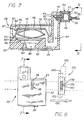
- FIG. 7 and 8 an alternate embodiment is illustrated wherein the movable wall 96 is oriented horizontally.
- like reference numbers refer to corresponding elements in the previously described embodiments, and in general, it will be appreciated that the above discussion applies in the description and operation of this further embodiment.
- the movable wall now moves vertically, and hence orthogonally to the directional motion of the carriage 12, and the on-board ink reservoir cartridge 20.
- the position of the ink level 98 can be detected with a linear ar ray 136 of discreet photosensors (138, 139, and 140 for example), oriented vertically.
- the viewing location 28 moves into the ink level sensing region 120, only the uppermost photo sensors will be tripped, the lowest photosensor in the array tripped corresponding to the location of the ink level 98.
- an illustration of the ink level sensing region 120 corresponds with a segment wherein a leading edge of the viewing location 28 moves in a direction 132 from left to right in Figure 8.
- Another illustrated ink sensing region 160 would correspond with movement in an opposite direction of the on-board ink reservoir cartridge 20. But as will be appreciated, if the array has a width dimension 162, as opposed to a vertically oriented series of points (as approximated by sufficiently small sensors) the width of the array must be taken into account as well as the width of the openings of the viewing location 28.
- a single photo sensor (not shown), can be positioned so as to trip when the ink level 98 falls below a pre-selected position corresponding to a selected minimum ink volume. This would initiate replenishment in an amount of ink equal to the difference in volume between this selected minimum volume and a "full" volume.
- a second single photo sensor (not shown) can be provided to detect a full condition.
Description
- This application is related to European patent applications 0583153, 0583154 and 0769383.
- The present invention relates generally to print head ink supply for high speed computer-driven printers such as ink jet printers and plotters. The invention relates more particularly to an ink supply system featuring replenishment of ink in a printer carriage-borne ink reservoir which supplies an ink-drawing carriage-borne print head, such replenishment being conveyed to the carriage-borne ink reservoir from a stationary ink supply off the printer carriage.
- In computer-driven ink jet printers and plotters, a supply of ink is usually held in a reservoir on the print head carriage immediately adjacent the print head to provide a ready ink supply to the print head. This reservoir is usually combined with the print head in a single cartridge. In such printers, for example, this "on-board" ink reservoir is ordinarily maintained at a sub-atmospheric, or negative, pressure, so that ink will not leak or "drool" from the print head. Various types of ink reservoirs are conventionally used, including refillable ink reservoir cartridges, which are mounted on the moveable printer carriage, throwaway replaceable cartridges, and combinations of on-board and remote or "off-board" ink reservoirs. When an off-board ink supply is used ink is drawn to feed a print head unit or cartridge, which usually incorporates the on-board ink reservoir mentioned. The ink may be transferred from the off-board ink supply reservoir to the carriage born print head unit via flexible tubing for example.
- In particular, certain known ink cartridges employ "spring bag" inner ink reservoir comprising a bag formed of flexible membranous sheet material with two side plates biased apart by a spring contained within. The spring, tending to increase the volume (and resisting shrinkage) of the bag, maintains a subatmospheric pressure within. Further information regarding such cartridges can be found in U.S. Patent Nos.: 5,280,300 issued January 18, 1994 to Fong, et al.; 5,325,119 issued June 28, 1994 to Fong; and 5,359,353 issued October 25, 1994 to Hunt et al., all of which are assigned to the assignee of the present application.
- It has been recognized that eliminating disposable ink cartridges, and, insofar as possible, waste of ink, in view of environmental concerns regarding the disposal of waste ink and ink containers, and further, providing lower purchase and operating costs to printer and plotter users, are desireable objectives. Provision of an off-board ink supply which can be easily refilled is a significant step in this direction as operators of the printer equipment can refill the ink supply at longer time intervals, and are not frequently disposing of waste ink cartridges or ink.
- Difficulties in providing such an off-board ink supply and on-board ink reservoir have been encountered. Particularly, the ready supply amount of ink in an on-board ink springbag reservoir, for example, must be maintained within certain limits, at the same time maintaining the negative pressure within the bag. This process is difficult, as infusion of ink into the reservoir must be regulated to prevent pressure within the bag from rising to atmospheric, and requires careful monitoring of ink volume in the bag of the on-board reservoir. One solution to monitoring ink volume is to "count drops" i.e. to monitor the amount of ink ejected from the print head by counting individual ejections of ink. This drop counting and other known methods tried have not yielded accurate results.
- Furthermore, introduction of air into the print head must be prevented in connection with replenishment of the ink supply to ensure proper printer operation. Moreover, movement of the print head carriage and consequently the flexible conduit between the off-board ink supply and the on-board reservoir causes fluctuations in pressure and delivery rate of ink being transferred, and also facilitate air bubbles traversing the conduit to contaminate the on-board reservoir. These conditions can compromise proper functioning of the print head if the air enters the on-board reservoir and is drawn into the print head or if internal pressure is raised to, or above, atmospheric by such pressure or flow fluctuations allowing ink to drool from the print head.
- These difficulties having been recognized, the present invention is directed to providing, at a reasonably low cost, a method for replenishing an on-board ink reservoir, thereby reducing waste. More particularly, a method is provided which uses an on-board ink reservoir maintained at a sub-atmospheric pressure, and includes monitoring the volume of ink in an on-board reservoir and replenishing it as required in a controlled manner.
- JP-A-59194855 discloses a method of sensing an ink level in a print ink reservoir in a computer-driven printer having a movable print head carriage, comprising the steps of: providing an ink reservoir having a housing and a discontinuity in said housing comprising an ink viewing location where an ink level related to the volume of ink in the ink reservoir can be observed; providing an ink sensing region; providing a beam of light through said ink volume sensing region and directed onto said ink reservoir ink viewing location; providing a sensor for detecting said beam of light; and detecting said beam of light, the light detected being altered by the ink level in said ink reservoir.
- EP-A-573274 also discloses printing apparatus provided with an ink amount detection device. The detection device comprises light emitting means, a transparent member and light receiving means.
- The present invention accordingly provides a method of sensing an ink level in a printer carriage-borne ink reservoir in a computer-driven printer having a removable print head carriage movable along a path of said print head carriage, the position of said print head carriage along said path being detectable by said printer, comprising the steps of:
- a. providing a carriage-borne ink reservoir having a rigid outer housing and an inner reservoir including a movable wall contained in said outer housing and movable with respect to said rigid outer housing, said inner reservoir defining a variable volume chamber within said rigid outer housing, said rigid outer housing further comprising an ink viewing location where an ink level indication is provided by an ink level indicator comprising said movable wall, said indicator and viewing location being configured so that the ink level indicator is illuminable by a beam of light directed onto said viewing location from outside the rigid outer housing, the position of said ink level indicator being movable with said movable wall and the position of the ink level indicator having a relationship to the volume of ink in the carriage-borne ink reservoir such that said volume of ink can be determined from the relative position of the ink level indicator and the rigid outer housing;
- b. providing at a known position along the path of said carriage-borne ink reservoir an ink level sensing region through which said carriage-borne ink reservoir travels with said carriage;
- c. moving said carriage-borne ink reservoir through said ink volume sensing region;
- d. providing a beam of light directed across the path of said carriage-borne ink reservoir at a first known location along the path of the carriage-borne ink reservoir within said ink level sensing region said beam of light being directed onto said ink reservoir ink viewing location when said reservoir moves through said ink volume sensing region;
- e. providing a light sensor for detecting said beam of light;
- f. detecting said beam of light, the light detected being altered by interception of said beam of light by the ink level indicator at the viewing location in said carriage-borne ink reservoir when said ink level indicator is positioned at the first known location of the beam of light within said ink sensing region, whereby the position of the ink level indicator is detected;
- g. detecting a second location along the path of the printer carriage and carriage-borne ink reservoir at the time the ink level indicator is detected at said first location, said second location being the position of said carriage and said carriage-borne ink reservoir when said ink level indicator is positioned at said first position, the position of the outer rigid housing being known at the time said ink level indicator is detected; and
- h. comparing the known positions of the rigid housing and ink level indicator at the time said ink level indicator is detected, whereby the volume is determinable from the known relationship of the position of the ink level indicator and the volume of ink within said variable volume chamber.
-
- In a more detailed aspect, an ink conduit having a flexible ink supply line portion is disposed between the off-board ink supply and the carriage-borne ink supply. Structure comprising a pressure and flow limiting and stabilization means is incorporated in the ink replenishment system, and is disposed adjacent the carriage-borne reservoir, to provide a controlled flow of ink to the carriage-borne reservoir in replenishment, allowing the carriage-borne reservoir to remain at subatmospheric pressure throughout a replenishment cycle. This flow limiting and stabilization means can comprise a constricted fluid conduit, and further may be defined by an inner lumen of a needle and septum connector between the carriage borne ink reservoir and the flexible supply line. Further, an air accumulator, including a riser and one-way air vent, is incorporated in said conduit to prevent air from reaching the print head. The one-way air vent allows air to exit the air accumulator but prevents the escape of ink and the entrance of air or other impurities.
- In a further more detailed aspect, a light source and photoelectric sensor can be employed to sense the ink level. Openings in the ink reservoir housing allow a line of sight through the cartridge in which the ink level, comprising a moveable wall of an inner springbag ink reservoir, is observable. The openings are sized so that a range of positions of the ink level are observable, and when it is mounted on a printer carriage the ink level can be sensed by a change in light emitted by the light source and received by the photoelectric sensor. When the carriage moves past the photosensor the ink level is detected as located at a direct line from the light source to the sensor a carriage position by a change in light sensed, and the position of the cartridge is known by virtue of the carriage position monitor with reference to an optical encoder bar and an optical sensor associated therewith. The relative positions of these elements being thus sensed, ink volume is determined according to a known relation of ink level position with respect to the rest of the cartridge.
- FIGURE 1 is a perspective view of a computer-driven printer, illustrating the environment of the invention;
- FIG. 2 is a perspective view of a print head cartridge used according to the invention and a connected off-board ink supply;
- FIG. 3 is an exploded perspective view of a print head ink cartridge for a thermal ink jet printer containing a collapsible ink reservoir structure;
- FIG. 4 is a schematic representation of an ink supply system used according to the invention in a computer-driven printer;
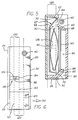
- FIG. 5 is a vertical cross section, partially in elevation view, of the cartridge of Figure 3 taken along line 5-5 therein;
- FIG. 6 is an elevational view of the cartridge of FIG. 5;
- FIG. 7 is a cross-sectional view, taken along line 7-7 in FIG. 8 of an alternate on-board ink reservoir print head cartridge used in the invention; and
- FIG. 8 is an elevational view taken on line 8-8 in FIG. 7 of the cartridge of FIG. 7.
-
- With reference to FIGURE 1 of the drawings, which are given by way of example and not by way of limitation, a computer-driven
printer 10, of the ink jet type wherein printing is performed by extremely small ejections of ink, as is known in the art, includes acarriage 12 slidably supported onsupports encoder bar 16 which in conjunction with an optical scanner (not shown) monitors the position of the carriage. On-board print head andink reservoir cartridges - An
ink cartridge 20 used in the invention is seen in FIG. 2 to comprise a molded rigid plastic resinouter housing 22, having acover plate 24 intended to be affixed as by cementing or welding to the remainder of the housing. The cartridge has an ink discharge aperture in its lowermost end wall (not shown) to which is affixed an electrically-drivenprint head 26. Aviewing location 28 is defined by a discontinuity in thehousing 22 defined by afirst slot 30 in afirst side 32, and, as can be seen in FIG. 3, asecond slot 34 aligned with the first slot, which allows a line of sight through the housing from the first side to a second, opposite,side 36. - With reference to both FIGS. 2 and 3, an
ink supply line 38 can be connected to thecartridge 20 via a connector, which in this embodiment comprises aseptum 40 formed of an elastomeric material inert with respect to ink and disposed in anopening 42 in thehousing 22, and aneedle 44 adapted to pierce the septum. This connector gives a connection capability free of contamination by air or other impurities. A capillary tube (not shown) comprising the interior lumen through the needle also acts as a pressure and flow fluctuation limiter with respect to ink replenishment of the on-board ink reservoir in thecartridge 20 from theflexible supply line 38, and stabilizes the flow at an amount below that which would raise the pressure within the ink reservoir of thecartridge 20 above a preselected subatmospheric pressure. The septum may be pre-slit to allow connection of a needle with a relatively blunt point, and the septum can be compressively loaded to effect a seal of any opening formed therethrough by insertion of theneedle 44 when it is withdrawn. - An
air accumulator 46 is incorporated in theink supply line 38 adjacent theconnector needle 44, and comprises ariser 48 and anair valve 50 formed of a porous membrane which allows air to pass therethrough, but will not allow ink to pass through. Acover plate 52, incorporating asmall opening 54 to allow escape of air, closes the top of theriser 48. Alayer 57 of non-volatile liquid, such as glycol, is disposed over the membrane, preventing air infiltration through the membrane and into the riser even though a vacuum is applied to the interior of theriser 48 of theaccumulator 46 lowering the pressure therein to subatmospheric. Alternatively or in addition to the provision of thelayer 57 of liquid, a check valve (not shown), such as a flapper or duck-bill valve biased to a closed position, can be provided. The check valve controls theopening 54 on the cover plate to allow escape of air from the riser and prevent air from being drawn into the riser if the pressure in the riser drops below atmospheric. Since it is essential that the riser remain relatively upright for the air accumulator to function properly to trap air bubbles, aledge 58 is incorporated in thehousing 22 to prevent rotation of theair accumulator 46 around a central axis of the needle connector. - In further embodiments, not shown, a conventional one-way valve, such as a duckbill or a flapper check valve, or a float valve and check valve combinations is substituted for the membrane air valve.
- A
ribbed connection portion 56 allows connection of the flexibleink supply line 38 to theriser 48. Theneedle 44 is preferably integral with the riser and formed of a similar ink-inert plastic. Theink supply line 38 is formed of an elastomer which does not react with print ink, and allows substantial flexing of the line as required to connect the cartridge moving on theprint carriage 12 to the stationary off-board ink supply 60 but resists excessive deformation due to positive and negative pressures within the supply line. - With particular reference to FIG. 2, an off-
board ink supply 60 incorporates asealable container 62 having anactuatable pump 64 configured to pressurize the interior of the container (or evacuate it if required). Adjacent the container avalve 66 controlling ink flow from thecontainer 62 through theink supply line 38 is provided, which, in conjunction with thepump 64 is employed in controlled replenishment of the on-board ink reservoir in thecartridge 20. This valve is a check valve having a cracking pressure less than the pressure to which the ink is pressurized by thepump 64, but greater than that which is required to hold it closed against the negative pressure within the on-board ink reservoir, and thus holds against sufficient vacuum as may be required within the system during normal operation of theprinter 10, but opens to allow replenishment when the system is pressurized by thepump 64. Alternatively, thevalve 66 can be an actuatable valve, for example a stopcock, which can be opened or closed as required. In another alternative embodiment, theink supply 60 is simply located vertically lower than thecartridge 20 by a vertical distance sufficient to maintain the negative pressure within the ink reservoir as required for normal printer function. This amount of vacuum usually implicates a vertical differential distance of at least three to seven inches. - An inlet tube (not shown) connected to the
supply line 38 is provided within theink supply container 62 to draw ink from the bottom of the container and avoid introducing air into theink supply line 38. Any air that is drawn into the ink supply line, however, is trapped by theair accumulator 46, and is expelled from the system through theair valve 50 when theink supply container 62 and line are pressurized by actuation of thepump 64. Alternatively, an ink-filled flexible bag (not shown) is sealingly coupled to the supply line, for example by a needle and septum connector as described above, and disposed within thecontainer 62, which arrangement allows pressurization of the ink supply without contact between stored ink and air within the container. In a further embodiment (not shown) such an ink bag is squeezed by opposing surfaces. And in a further alternate embodiment a syringe pump (not shown) comprising a variable volume chamber connected to the conduit in conjunction with one-way valves disposed in the conduit on each side of the point of connection is used to pressurize the ink in the ink supply conduit. - As will be apparent, ink flow in the replenishment system into the on-board
ink reservoir cartridge 20 is stabilized, as well as metered, by the capillary segment comprising inner lumen of theneedle 44 of the connector. The constricted capillary tube allows only a preselected flow through the connector into the ink cartridge, with a small known and allowable variation, over an range of pressure fluctuations in theink supply line 38 occasioned by pressurization for replenishment, overlain with pressure fluctuations caused by movement of theprint head carriage 12 and consequently thesupply line 38. The amplitude of pressure and flow fluctuations in the supply line is attenuated and a relatively stable preselected flow rate and fluid pressure results at a distal end of theneedle 44. This preselected flow rate is chosen so that the on-board reservoir of thecartridge 20 will be filled relatively slowly so that the pressure in the ink reservoir is maintained at subatmospheric, or "negative" pressure during replenishment, even though the ink in thesupply container 62 andsupply line 38 is under a superatmospheric, or "positive" pressure. Slow filling also allows monitoring during filling to prevent over- or under-filling. The way in which a negative pressure in the on-board ink reservoir of the illustrated embodiment is created and maintained is discussed below, and it will be appreciated that this negative pressure can be maintained as long as the pressure and flow rate of replenishment ink entering the on-board ink reservoir does not overwhelm its inherent pressure regulating function. - With reference now to FIGS. 3 and 5, an inner
ink reservoir structure 67 is formed within thehousing 22, comprised in part of the housing, formed of a relatively rigid inert plastic resin, acting as a frame and also part of an inner inclosure of thereservoir 67, and a flexible inkbag membranous sheet 68, having a low elasticity and also inert with respect to ink, attached thereto by heat bonding the peripheral edges of the membranous sheet to the inner periphery of the housing. Anoutermost ledge 70 of a series of concentric ledges is provided around the interior of the housing for this purpose. The inner ink reservoir structure contains a stainlesssteel pressure regulator 72 which in turn is comprised of a pair of spaced substantiallyparallel plates spring 78 into engagement with theflexible membranous sheet 68 and a furtherconcentric ledge 80. Achamber 82 of variable volume is thus formed within the housing, which chamber is in fluid communication with theconnector septum 40 via achannel 84 formed in the housing, and the print head via afurther channel 86. An entrance to saidfurther channel 86 to the print head is defined by an innermostconcentric ledge 88 and afilter 90 supported thereby and attached thereto at the peripheral edges of the filter. The lowermost portion of the outer housing 22 (as viewed in FIG. 5) is provided with anink discharge aperture 92 through which ink is downwardly discharged from thechannel 86 leading from thefilter 90 to theprint head 26. - The pressure
regulator side plates membranous sheet 68. One ormore openings 94 is provided in each plate to allow ink to flow therethrough to thefilter 90 in the assembled ink reservoir. The pressure regulator is reversible, facilitating assembly of thecartridge 20 After installing theseptum 40 andprint head 26, thefilter 90,pressure regulator 72,membranous sheet 68, and coverplate 24 are attached in that order. As will be apparent, theconcentric ledges membranous sheet 68 to thehousing 22, theregulator 72 is placed in position and pre-loaded by collapsing it partially against the spring force such that it is in a prestressed condition inside the inner ink reservoir bag chamber formed by thehousing 22 andmembranous sheet 68. The amount of this pre-stressing is readily controllable by the designer selecting the desired characteristics and amount of compression of thespring 78. - The
flexible membranous sheet 68 and aside plate 74 of theregulator 72 forms amovable wall 96 of the inner ink reservoir, and this moveable wall gradually moves towards thehousing 22 as the reservoir is evacuated of ink by theprint head 26 in operation. The moveable wall is visible along a line of sight through theslots viewing location 28. Themembranous sheet 68 is sized with enough extra membranous sheet material near the edges of attachment to the outermostconcentric ledge 70 of thehousing 22 that the wall is freely moveable with the side plate between full and empty positions as best indicated in FIG. 5. With reference to FIGS. 5 and 6, it will be appreciated that when theinner ink reservoir 67 is filled with ink, themovable wall 96 and the inner ink reservoir will appear as anink level 98 comprising an opaque obstruction in a line of sight through the housing at theviewing location 28. - The
pressure regulator 72 constantly biases themovable wall 96 to the furthest position away from thehousing 22 allowed by the volume of ink presently in the inner ink reservoir at any instant of time. Thus theink level 98 will obstruct as much of the viewing location as the volume of ink will allow, and the position of this ink level is reliably indicative of the true volume of ink in the inner reservoir according to a readily determined functional relationship between the position of the ink level and the volume of ink remaining in the inner reservoir bag. This functional relationship is non-linear, but can be readily ascertained by empirical methods, or calculated, for example by use of computer-aided modeling techniques. Once this functional relationship is known, it can be used to correlate ink level to ink volume in the inner ink reservoir of thecartridge 20. - With reference now to FIGS. 4, 5 and 6, further components and operation of an on-board ink
reservoir replenishment system 100 according to the invention will now be described. As is known in the art, the position of the carriage is determined by a position monitoring system including anoptical encoder 102 incorporating theencoder bar 16 as the positional reference. By means of this position monitor the position of thecarriage 12 at any instant of time is known to anink replenishment controller 104 embodied in the printer (not shown). The controller further comprises aprocessor 106,memory 108, andclock 110. As will be apparent, components of the controller can be embodied on a single IC chip, and the specifics of implementation of these system elements can be one of the well known ways employed by persons skilled in the art. Use of the existing carriage position monitor of the printer results in lower costs. - The
ink replenishment controller 104 controls replenishment of ink in the on-boardink reservoir cartridge 20, effecting ink replenishment when ink volume in the cartridge is drawn below a pre-selected amount by theprint head 26 in printer operation. Replenishment is affected by providing the over-pressure required to move ink from the off-board ink supply 60 throughink supply line 38 and the needle connector capillary tube incorporated in theconnector needle 44 and into the on-board inner ink reservoir chamber. If anactuatable valve 66 is used instead of a check valve as before described, avalve actuator 112 is provided to actuate thevalve 66 in theink supply line 38 as required to open and close a fluid communication through the ink supply line. Apressure actuator 114 is provided to actuatepump 64, which provides pressure to the off-board ink supply. An appropriate interface between theink replenishment controller 104 and the valve and pressurization actuators is denominated anactuator controller 116 in the illustrated embodiment. - The volume of ink in the on-board ink reservoir of
ink cartridge 20 is monitored by sensing the relative position of theink level indicator 98, comprising themovable wall 96 of the opaque ink-filled inner ink reservoir ink bag, as viewed in a line of sight through theviewing location 28 in the cartridge. With reference particularly to Figure 4, a hypotheticalink sensing region 120, defined by the region between twoimaginary plains light source 126 andphotosensor 128 are positioned in line so as to project light along a line of sight through theviewing location 28 of thecartridge 20 when the cartridge is moved through the beam of projected light from the light source to the photosensor. Theink sensing region 120 represents in reality simply the range of positions of thecarriage 12 where a direct line from the light source to the photosensor passes through theopenings ink level 98. It can be thought of as any segment of the path of carriage motion through which a single discrete point on the carriage passes during the time when the openings are so aligned with the light source and photosensor, and thus would extend a distance commensurate with or less than the width of the openings, and specifically it can be referenced as that section of theencoder bar 16 traversed by theoptical encoder 102 during that time. - Thus, this ink level sensing region wherein the position of the
ink level 98 defined by themovable wall 96 with respect to thehousing 22 of thecartridge 20 can be sensed will always be known, as the positional relationship between theink cartridge 20,carriage 12 andviewing location 28 are always known due to the fixed position of the cartridge in the print head carriage. This allows sensing of the ink level only when the carriage, and therefore the viewing location, is in the ink sensing region. As will be apparent, the system will not sense the ink level unless the carriage is in the ink sensing region, avoiding the requirement to distinguish thecover plate 24 or edges of theopenings ink level 98. As will also be apparent, openings (not shown) in the carriage must be provided adjacent the viewing location for light to pass through if the carriage would otherwise obstruct the line of sight from thelight source 126 to thephotosensor 128. - As an alternative to the above, the
carriage 12 could act to screen light from thelight source 126, for example by making the width of openings therein with respect to the direction of motion of the carriage the same or less than the width of theopenings viewing location 28. Thus light could only reach thephotosensor 128 when the carriage was in the ink sensing region associated with a particular pen. In this latter case however, the ink level must be distinguished by the system from an edge of the openings comprising theviewing location 28, and this requires the direction of motion of the carriage to be taken into account. - Returning to the illustrated embodiment, when the
carriage 12 moves into the ink level sensing region the position of the ink level will be sought by theink replenishment controller 104. The position is sensed when theopaque ink level 96 of the movable wall of theinner ink reservoir 67 interrupts the beam of light projected along the line of sight fromlight source 126 to thephotosensor 128. More properly, the position of theprint head carriage 12 is sensed by theoptical encoder 102 at a time instant when the photosensor detects a change in the light projected due to obstruction by theink level 98. The position of the ink level being known at that instant to correspond to the position of a direct line between thelight source 126 and thephotosensor 128, and the position of the carriage being known at that instant from theoptical encoder 102 andencoder bar 16 of the position monitor, the relative positions of theink level 98 and on-boardink reservoir cartridge 20 are then known for that time instant. Given this information, theprocessor 106 can correlate this information with the volume of ink in the on-board reservoir at that instant from the known functional relationship between the position of themovable wall 96 comprising theink level 98 and the inklevel cartridge housing 22 which is stored inmemory 108. This functional relationship can be stored in the form of a look-up table or a numerical series approximating the function, or a series of calculation steps, for example, as is known in the art. - In a further embodiment, from data generated by the
optical encoder 102 andphotosensor 128, the system simply monitors the direction and speed of movement of thecarriage 12, and the pattern of light detected, including the duration of each period of light and dark detected, as the carriage travels through the line of sight between thelight source 126 andphotosensor 128. The elements of the pattern corresponding to the carriage andcartridges ink level 98 position in each cartridge. Correlation of the pattern of light thus detected to the volume of ink in each cartridge is here again according to a functional relationship previously determined and programed in thememory 108 of thecontroller 104. This correlation is used to determine when aparticular cartridge 20 needs replenishment, and can be used to monitor refilling. - While the illustrated embodiment employs a reservoir having one
movable wall 96, it will be apparent that the invention can be applied to an ink reservoir having two movable walls (and hence two viewing locations associated therewith) on opposed sides. In this embodiment the distance between movable walls (not shown) is related to the volume of ink in the reservoir. After the relative positions of the two walls are sensed as in the single wall embodiment, but now with respect to each other and not the housing, the volume is then determined based on a stored function previously determined by empirical or mathematical methods relating the distance between walls and volume incorporated in a controller as with the illustrated embodiment. - In a further alternate embodiment (not shown) a reservoir having two movable walls and one viewing location wherein one of the moveable walls may be viewed is provided. The two movable walls move approximately the same distance in opposite directions in filling or evacuating the ink reservoir. This embodiment would function in all other ways just as a reservoir with one
movable wall 96 within ahousing 22, but would be inherently less able to accurately monitor the volume of ink in the reservoir as the two walls may not move uniformly, and the two walls may both be shifted in a single direction with respect to thehousing 22, giving too high or low an ink level as seen within the viewing location. - In operation the ink volume is monitored periodically, for example once for each time a complete page is printed by the
printer 10. The minimum volume of ink required in the on-board ink reservoir corresponds, for example, to that needed to print a full black-out page. Given these parameters by way of example, if the minimum volume is approached replenishment is initiated and can be in either of two forms: 1) replenishment by filling until reaching a pre-selected volume corresponding to "full" with more frequent sensing during filling; or 2) replenishment of a pre-determined volume, the replenishment volume being simply a set amount corresponding to the difference between the pre-selected minimum volume limit and "full," or another amount based upon the actual volume sensed. With the second method a reserve capacity to mitigate over filling and/or a level check at a calculated time the volume theoretically approaches full can be employed. - Replenishment ink is metered into the on-board inner ink reservoir of the
ink cartridge 20 as mentioned above, in the illustrated embodiment by providing a constricted capillary tube comprising the interior lumen of theneedle 44 of the needle connector also including theseptum 40 in the ink cartridge. As can be appreciated, applying a pre-selected constant pressure to theink supply 60, openingvalve 66 allowing flow of ink through theink supply line 38 to theair accumulator 46 incorporating theriser 48 andneedle 44 of the needle connector, will provide a superatmospheric pressure in the riser of the air accumulator. As can be further appreciated, a known volume of ink will pass through the capillary tube of theneedle 44 of a known diameter and length in a known amount of time at a ink supply pressure of this selected value. This pressure is chosen to provide a slow filling rate allowing negative pressure to be maintained within theinner ink reservoir 82 by thepressure regulator 72. As can further be appreciated, the capillary tube is sized so that periodic pressure spikes occasioned by movement of the print carriage and supply line or opening of thevalve 66 for example will be attenuated, and the flow through the capillary tube will be limited so that at no time will the function of thepressure regulator 72 maintaining a sub-atmospheric pressure within the on-board ink reservoir be compromised. - The slow filling rate also allows monitoring of the ink volume during filling mentioned above, which can be done every few seconds, or alternatively a period defined by counting a preselected number of lines printed if printing is ongoing during replenishment.
Clock 110 is provided in theink replenishment controller 104 to perform any required timing function in one embodiment. In a further embodiment the known flow rate through the capillary tube can be used by the controller to add a selected volume of ink to the on-board reservoir 82 by timing the period wherein the ink supply is pressurized. - After sufficient time to meter a selected amount of ink into the on-board ink reservoir has elapsed, and/or a full volume of ink in the
reservoir 82 is sensed by the system, thepressure actuator 114 and pump 64 is stopped and thevalve 66 closes or is closed, sealing off the on-board ink supply. This sealing off of the ink supply allows a sub-atmospheric pressure to be maintained in the on-board reservoir over the period of time between ink replenishments. - As before mentioned, the
air accumulator 46 allows any air which may transit theink supply tube 38 to accumulate in theriser 48 against theair valve membrane 50. During pressurization of the ink supply pressure within the air accumulator forces this trapped air though the membrane and out of the system through theopening 54 in thecover plate 52 of the air accumulator. The air valve is configured so that air will not pass therethrough in the opposite direction, for example by provision of a layer ofliquid 57 on top of themembrane 50 excluding air therefrom. Such a layer of liquid can be formed of glycol or other substance which does not evaporate under normal printer operating conditions. Alternatively to or in conjunction with providing such a layer of liquid, a one-way check valve (such as a duckbill, biased-closed flapper valve, or the like) could be incorporated in thecover 52 sealing off theopening 54 therethrough for air escape except during the time that air is being forced out of theriser 48 and through such a valve during replenishment. Therefore theair valve 50 will hold a vacuum against the sub-atmospheric pressure within the on-board reservoir tending to draw ink through the capillary of theneedle 44, the system otherwise being sealed by closure of thevalve 66 in theink supply line 38. Such membrane materials are commercially available from a number of manufacturers. For example GORETEX (a registered trademark of the manufacturer W.L. Gore & Associates for a teflon micropore material) can be used. As mentioned a check valve such as a duckbill or flapper valve (not shown) could be added to the system outside the membrane to further assure maintenance of a negative pressure in the system, or even be substituted for the membrane. - In another embodiment, after a desired amount of ink is metered into the on-
board reservoir 67 thepump 64 is reversed and pressure in thesupply line 38 is reduced to subatmospheric. Theconnector septum 40 being located at the uppermost portion of the on-board reservoir, any air introduced into thereservoir 67 will collect adjacent the connector. When the pressure is turned to a vacuum the collected air will be drawn out through theneedle 44 and into theair accumulator 46, or alternatively through thesupply line 38 to an off-board air accumulator (not shown) associated with theink supply 60 for example. - With reference now to Figure 6, it can be appreciated that for purposes of providing increased accuracy in sensing the
ink level 98, thelight source 126 should be made sufficiently small, and likewise the photo sensor (not shown) is sized to reliably detect a change in light sensed, i.e. to consistently "trip" at the same pre-selected location of theink level 98, preferably the location of a hypothetical direct line between the light source and photosensor for sake of simplicity. As can be appreciated, this tripping of the photosensor will occur at some instant of time when some portion of theviewing location 28 is intersected by this hypothetical line from the light source to the photosensor. For purposes of illustration this would occur when a leading edge corresponding withline 133 is within asegment 120 between thelines cartridge 20 is moving with the carriage (not shown) in adirection 132 from left to right as viewed in Figure 6. As mentioned, the width of thisspace 120 is equal to thewidth 130 betweenlines viewing location 28. - In one embodiment, tripping of the
photo sensor 128 may be "enabled" while thecarriage 12 is within the ink level sensing region and not enabled at other times. This would eliminate noise signals caused by the photo sensor tripping pursuant to the passage of thecover plate 24 or anedge 134 of the first andsecond slots housing 22, for example, as previously discussed. - Referring to Figures 7 and 8, an alternate embodiment is illustrated wherein the
movable wall 96 is oriented horizontally. Here, like reference numbers refer to corresponding elements in the previously described embodiments, and in general, it will be appreciated that the above discussion applies in the description and operation of this further embodiment. However, the movable wall now moves vertically, and hence orthogonally to the directional motion of thecarriage 12, and the on-boardink reservoir cartridge 20. In this embodiment, the position of theink level 98 can be detected with alinear array 136 of discreet photosensors (138, 139, and 140 for example), oriented vertically. As theviewing location 28 moves into the inklevel sensing region 120, only the uppermost photo sensors will be tripped, the lowest photosensor in the array tripped corresponding to the location of theink level 98. Again, an illustration of the inklevel sensing region 120 corresponds with a segment wherein a leading edge of theviewing location 28 moves in adirection 132 from left to right in Figure 8. Another illustratedink sensing region 160 would correspond with movement in an opposite direction of the on-boardink reservoir cartridge 20. But as will be appreciated, if the array has awidth dimension 162, as opposed to a vertically oriented series of points (as approximated by sufficiently small sensors) the width of the array must be taken into account as well as the width of the openings of theviewing location 28. - Alternatively, a single photo sensor (not shown), can be positioned so as to trip when the
ink level 98 falls below a pre-selected position corresponding to a selected minimum ink volume. This would initiate replenishment in an amount of ink equal to the difference in volume between this selected minimum volume and a "full" volume. A second single photo sensor (not shown) can be provided to detect a full condition. - Persons skilled in the art will readily appreciate that various modifications can be made from the preferred embodiment of the invention disclosed herein and that the scope of protection is intended to be defined only by the limitations of the appended claims.
Claims (16)
- A method of sensing an ink level (98) in a printer carriage-borne ink reservoir (20) in a computer-driven printer (10) having a movable print head carriage (12) movable along a path of said print head carriage, the position of said print head carriage along said path being detectable by said printer, comprising the steps of:a. providing a carriage-borne ink reservoir (20) having a rigid outer housing (22) and an inner reservoir including a movable wall (96) contained in said outer housing and movable with respect to said rigid outer housing, said inner reservoir defining a variable volume chamber within said rigid outer housing, said rigid outer housing further comprising an ink viewing location (28) where an ink level indication is provided by an ink level indicator comprising said movable wall, said indicator and viewing location being configured so that the ink level indicator is illuminable by a beam of light directed onto said viewing location from outside the rigid outer housing, the position of said ink level indicator being movable with said movable wall and the position of the ink level indicator having a relationship to the volume of ink in the carriage-borne ink reservoir such that said volume of ink can be determined from the relative position of the ink level indicator and the rigid outer housing;b. providing at a known position along the path of said carriage-borne ink reservoir an ink level sensing region (120) through which said carriage-borne ink reservoir (20) travels with said carriage (12);c. moving said carriage-borne ink reservoir (20) through said ink volume sensing region (120);d. providing a beam of light directed across the path of said carriage-borne ink reservoir (20) at a first known location along the path of the carriage-borne ink reservoir within said ink level sensing region (120), said beam of light being directed onto said ink reservoir ink viewing location (28) when said reservoir (20) moves through said ink volume sensing region (120);e. providing a light sensor (128) for detecting said beam of light;f. detecting said beam of light, the light detected being altered by interception of said beam of light by the ink level indicator at the viewing location in said carriage-borne ink reservoir (20) when said ink level indicator is positioned at the first known location of the beam of light within said ink sensing region (120), whereby the position of the ink level indicator is detected;g. detecting a second location along the path of the printer carriage (12) and carriage-borne ink reservoir (20) at the time the ink level indicator is detected at said first location, said second location being the position of said carriage and said carriage-borne ink reservoir when said ink level indicator is positioned at said first position, the position of the outer rigid housing being known at the time said ink level indicator is detected; andh. comparing the known positions of the rigid housing (22) and ink level indicator at the time said ink level indicator is detected, whereby the volume is determinable from the known relationship of the position of the ink level indicator and the volume of ink within said variable volume chamber.
- The method of claim 1, further comprising the step of determining the volume of ink in said carriage-borne ink reservoir (20) based on the relative positions of the rigid outer housing (22) and the ink level indicator.
- The method of claim 1 or 2, further comprising the step of sensing the relative position of said ink level indicator and said rigid outer housing (22) of said carriage-borne ink reservoir (20) when the reservoir is moved through the ink volume sensing region by comparing said first position to said second position, thereby determining the position of the carriage when the light beam is directed onto said ink reservoir viewing location (28) and a change in the detected light projected across the ink sensing region is detected by said light sensor.
- The method of any preceding claim, further comprising the step of configuring the ink level indicator to move with respect to the rigid outer housing (22) of the carriage-borne ink reservoir in a direction parallel with the motion of said carriage and said carriage-borne ink reservoir.
- The method of any preceding claim, further comprising the steps of:a. providing a single photosensor (128) at said first location in said ink sensing region to act as said light sensor;b. providing an encoder (102) for sensing the position of the carriage and said carriage-borne ink reservoir (20);c. providing an ink level indicator comprising said movable wall (96) and opaque ink contained in said variable volume chamber, said ink acting to intercept light directed at said viewing location and thus alter the light detected at said photosensor.
- The method of claim 5, further comprising the step of providing a spring bag (68) within said ink reservoir housing (22), said spring bag (68) including said moveable wall viewable through said rigid outer housing (22) at said ink level viewing location.
- The method of claim 6, wherein said spring bag has only one moveable wall (96).
- The method of any preceding claim, further comprising the steps of:a. providing an off-board ink supply (60) positioned other than on the moveable carriage (12);b. replenishing the volume of ink in said carriage-borne ink reservoir from the off-board ink supply, said replenishment being based on sensed ink level indicator position with respect to said rigid outer housing (22).
- The method of claim 8, further comprising the steps of:a. providing a flexible ink supply conduit (38) between said off-board ink supply (60) and said ink reservoir (20);b. providing a pressure differential between said carriage-borne ink reservoir (20) and said off-board ink supply (60) causing ink to flow through said ink supply conduit (38) from said off-board ink supply (60) to said carriage-borne ink reservoir (20).
- The method of claim 9, further comprising the step of limiting and stabilizing the flow of ink through said flexible ink supply conduit (38) into said ink reservoir (20) to minimize pressure and flow variations caused by movement of the carriage (12), ink reservoir (20), and supply conduit (38).
- The method of claim 10, further comprising the step of providing a constriction (44) in said flexible ink supply conduit adjacent said ink reservoir (20) to limit the magnitude of the rate of flow and pressure and flow rate variations of a replenishing flow of ink into said ink reservoir (20).
- The method of claim 9, further comprising the steps of:a. providing a riser (48) fluidly connected to the flexible ink supply conduit (38) configured to capture air in said conduit before said air can enter said ink reservoir (20);b. providing in said riser (48) an air vent configured to allow passage of air out of said conduit, but preventing escape of ink from said air vent.
- The method of claim 12, further comprising the step of providing a membrane in said air vent configured to allow passage of air through the membrane and out of said conduit, but at the same time prevent escape of ink from said air vent.
- The method of any of claims 8 to 13, further comprising the steps of:a. providing an ink volume capacity in said carriage-borne ink reservoir (20) at least as great as a volume required to print one page completely covered with ink;b. sensing the volume of ink in said ink reservoir (20) once each page is printed.
- The method of any of claims 8 to 14, further comprising the steps of:a. providing an air accumulator (46) and one-way air valve (50, 57) in fluid communication with said flexible ink supply conduit (38) and positioned adjacent said carriage-borne ink reservoir (20);b. preventing air from entering said ink reservoir (20) by accumulating air in the accumulator (46);c. forcing air from the accumulator (46) through said one-way air valve (50, 57).
- The method of claim 15, further comprising the step of providing said one-way air valve comprising a membrane (50) which allows flow of air through the membrane but prevents flow of ink therethrough.
Applications Claiming Priority (2)
| Application Number | Priority Date | Filing Date | Title |
|---|---|---|---|
| US08/545,964 US5757390A (en) | 1992-08-12 | 1995-10-20 | Ink volume sensing and replenishing system |
| US545964 | 1995-10-20 |
Publications (2)
| Publication Number | Publication Date |
|---|---|
| EP0769382A1 EP0769382A1 (en) | 1997-04-23 |
| EP0769382B1 true EP0769382B1 (en) | 1999-03-24 |
Family
ID=24178269
Family Applications (1)
| Application Number | Title | Priority Date | Filing Date |
|---|---|---|---|
| EP96306412A Expired - Lifetime EP0769382B1 (en) | 1995-10-20 | 1996-09-04 | Method and device for detecting the ink level in a cartridge |
Country Status (4)
| Country | Link |
|---|---|
| US (1) | US5757390A (en) |
| EP (1) | EP0769382B1 (en) |
| JP (1) | JP4290771B2 (en) |
| DE (1) | DE69601851T2 (en) |
Families Citing this family (87)
| Publication number | Priority date | Publication date | Assignee | Title |
|---|---|---|---|---|
| US6273560B1 (en) * | 1994-10-31 | 2001-08-14 | Hewlett-Packard Company | Print cartridge coupling and reservoir assembly for use in an inkjet printing system with an off-axis ink supply |
| JP3507261B2 (en) * | 1995-12-26 | 2004-03-15 | キヤノン株式会社 | Liquid supply method for liquid discharge head and liquid discharge recording apparatus |
| US6206512B1 (en) | 1999-01-29 | 2001-03-27 | Hewlett-Packard Company | Replaceable ink delivery tube system for large format printer |
| US6113229A (en) * | 1996-10-07 | 2000-09-05 | Hewlett-Packard Company | Interchangeable fluid interconnect attachment and interface |
| US7188918B2 (en) * | 1997-01-21 | 2007-03-13 | Hewlett-Packard Development Company, L.P. | Ink delivery system adapter |
| JPH10211716A (en) * | 1997-01-29 | 1998-08-11 | Sony Corp | Printer |
| US6076913A (en) * | 1997-03-04 | 2000-06-20 | Hewlett-Packard Company | Optical encoding of printhead service module |
| US7832817B2 (en) * | 1997-07-15 | 2010-11-16 | Silverbrook Research Pty Ltd | Recyclable printing device with tamper protection |
| JPH11138771A (en) * | 1997-11-06 | 1999-05-25 | Brother Ind Ltd | Ink-jet printer |
| US6196651B1 (en) * | 1997-12-22 | 2001-03-06 | Hewlett-Packard Company | Method and apparatus for detecting the end of life of a print cartridge for a thermal ink jet printer |
| US6155664A (en) * | 1998-06-19 | 2000-12-05 | Lexmark International, Inc. | Off-carrier inkjet print supply with memory |
| GB9822875D0 (en) * | 1998-10-21 | 1998-12-16 | Xaar Technology Ltd | Droplet deposition apparatus |
| JP2000334976A (en) * | 1999-05-31 | 2000-12-05 | Canon Inc | Ink jet recorder, ink supplying device and method for supplying ink |
| DE60044020D1 (en) * | 1999-11-05 | 2010-04-29 | Seiko Epson Corp | RECORDING DEVICE OF THE INK JET TYPE AND METHOD OF INK SUPPLYING THE UNDER TANK USING THE SAME DEVICE AND METHOD FOR CONTROLLING THE AMOUNT OF INK OF THE UNDER TANK BY MEANS OF THE SAME DEVICE |
| US6598965B1 (en) * | 1999-11-30 | 2003-07-29 | Hewlett-Packard Company, L.P. | Fixer usage generation technique for inkjet printers |
| US6431670B1 (en) * | 2000-02-14 | 2002-08-13 | Hewlett-Packard Company | Ink level sensing method and apparatus |
| US6243115B1 (en) | 2000-03-09 | 2001-06-05 | Lexmark International, Inc. | Pressurized ink supply and delivery system for an ink jet printer |
| US6328424B1 (en) | 2000-06-13 | 2001-12-11 | Lexmark International, Inc. | Inkjet cartridge with simultaneous electrical and fluid connections |
| JP2002160354A (en) * | 2000-11-28 | 2002-06-04 | Fuji Photo Film Co Ltd | Image recording apparatus and method |
| US6508545B2 (en) * | 2000-12-22 | 2003-01-21 | Hewlett-Packard Company | Apparatus for providing ink to an ink jet print head |
| US6908179B2 (en) * | 2001-04-04 | 2005-06-21 | Eastman Kodak Company | Ink level and negative pressure control in an ink jet printer |
| US6607262B2 (en) | 2001-06-18 | 2003-08-19 | Hewlett-Packard Company | Reserving ink for printer servicing purposes |
| JP2003053946A (en) * | 2001-08-22 | 2003-02-26 | Canon Inc | Imaging apparatus |
| JP3705208B2 (en) * | 2002-01-16 | 2005-10-12 | セイコーエプソン株式会社 | Ink jet recording apparatus control method and ink jet recording apparatus |
| US7147310B2 (en) * | 2002-01-30 | 2006-12-12 | Hewlett-Packard Development Company, L.P. | Printing-fluid container |
| US7744202B2 (en) * | 2002-01-30 | 2010-06-29 | Hewlett-Packard Development Company, L.P. | Printing-fluid container |
| US6962408B2 (en) * | 2002-01-30 | 2005-11-08 | Hewlett-Packard Development Company, L.P. | Printing-fluid container |
| US7452061B2 (en) * | 2002-01-30 | 2008-11-18 | Hewlett-Packard Development Company, L.P. | Method and device for filling a printing-fluid container |
| US6773098B2 (en) * | 2002-09-26 | 2004-08-10 | Eastman Kodak Company | Method of filling ink supply bag for ink cartridge |
| US7063399B2 (en) * | 2003-06-25 | 2006-06-20 | Lexmark International, Inc. | Imaging apparatus and method for facilitating printing |
| US7004564B2 (en) | 2003-07-31 | 2006-02-28 | Hewlett-Packard Development Company, L.P. | Printing-fluid container |
| US7104630B2 (en) * | 2003-07-31 | 2006-09-12 | Hewlett-Packard Development Company, L.P. | Printing-fluid container |
| US6959985B2 (en) * | 2003-07-31 | 2005-11-01 | Hewlett-Packard Development Company, L.P. | Printing-fluid container |
| JP4529405B2 (en) * | 2003-09-30 | 2010-08-25 | ブラザー工業株式会社 | Inkjet recording device |
| US7234787B2 (en) * | 2004-01-08 | 2007-06-26 | Eastman Kodak Company | Liquid level detection method and apparatus |
| US7210771B2 (en) * | 2004-01-08 | 2007-05-01 | Eastman Kodak Company | Ink delivery system with print cartridge, container and reservoir apparatus and method |
| US20050157112A1 (en) | 2004-01-21 | 2005-07-21 | Silverbrook Research Pty Ltd | Inkjet printer cradle with shaped recess for receiving a printer cartridge |
| US7448734B2 (en) | 2004-01-21 | 2008-11-11 | Silverbrook Research Pty Ltd | Inkjet printer cartridge with pagewidth printhead |
| US7188937B2 (en) * | 2004-01-29 | 2007-03-13 | Hewlett-Packard Development Company, L.P. | Printing-fluid venting assembly |
| US7303267B2 (en) * | 2004-04-02 | 2007-12-04 | Kenneth Yuen | Actuator for automatic ink refill system |
| US20060095280A1 (en) * | 2004-11-03 | 2006-05-04 | Lexmark International, Inc. | Method and apparatus for paying for printing materials in a printer over the usage time of a printer cartridge |
| JP2007007902A (en) * | 2005-06-28 | 2007-01-18 | Fujifilm Holdings Corp | Ink tank and inkjet recorder |
| US7475971B2 (en) * | 2005-12-02 | 2009-01-13 | Xerox Corporation | Ink delivery system |
| JP4872336B2 (en) * | 2005-12-19 | 2012-02-08 | ブラザー工業株式会社 | Inkjet recording device |
| US8967044B2 (en) * | 2006-02-21 | 2015-03-03 | R.R. Donnelley & Sons, Inc. | Apparatus for applying gating agents to a substrate and image generation kit |
| US7419234B2 (en) * | 2006-10-27 | 2008-09-02 | Static Control Components, Inc. | Method and apparatus for spoofing imaging devices |
| US8272704B2 (en) | 2008-05-22 | 2012-09-25 | Zipher Limited | Ink containment system and ink level sensing system for an inkjet cartridge |
| US8091993B2 (en) * | 2008-05-22 | 2012-01-10 | Videojet Technologies Inc. | Ink containment system and ink level sensing system for an inkjet cartridge |
| JP5239899B2 (en) * | 2008-07-29 | 2013-07-17 | 株式会社リコー | Image forming apparatus |
| US8419157B2 (en) * | 2010-02-26 | 2013-04-16 | Palo Alto Research Center Incorporated | Apparatus for controlled freezing of melted solid ink in a solid ink printer |
| JP2011201067A (en) * | 2010-03-24 | 2011-10-13 | Brother Industries Ltd | Set of cartridges and printer |
| JP5565029B2 (en) * | 2010-03-29 | 2014-08-06 | セイコーエプソン株式会社 | Liquid container and liquid consuming device |
| US8303098B2 (en) | 2010-05-07 | 2012-11-06 | Xerox Corporation | High flow ink delivery system |
| US8556372B2 (en) | 2011-02-07 | 2013-10-15 | Palo Alto Research Center Incorporated | Cooling rate and thermal gradient control to reduce bubbles and voids in phase change ink |
| US8506063B2 (en) | 2011-02-07 | 2013-08-13 | Palo Alto Research Center Incorporated | Coordination of pressure and temperature during ink phase change |
| US8562117B2 (en) | 2011-02-07 | 2013-10-22 | Palo Alto Research Center Incorporated | Pressure pulses to reduce bubbles and voids in phase change ink |
| US11809100B2 (en) | 2012-03-05 | 2023-11-07 | Landa Corporation Ltd. | Intermediate transfer members for use with indirect printing systems and protonatable intermediate transfer members for use with indirect printing systems |
| US20130242010A1 (en) * | 2012-03-16 | 2013-09-19 | Brian J. Kwarta | Method for venting air with a membrane |
| US20130242008A1 (en) * | 2012-03-16 | 2013-09-19 | Brian J. Kwarta | Ink supply having membrane for venting air |
| TWI600550B (en) * | 2012-07-09 | 2017-10-01 | 滿捷特科技公司 | Printer having ink delivery system with air compliance chamber |
| RU2018105185A (en) * | 2012-08-10 | 2019-02-25 | Сейко Эпсон Корпорейшн | LIQUID CONTAINER, LIQUID CONSUMPTION DEVICE, LIQUID FEEDING SYSTEM AND LIQUID CONTAINER UNIT |
| US9180674B2 (en) | 2013-02-08 | 2015-11-10 | R.R. Donnelley & Sons Company | System and method for supplying ink to an inkjet cartridge |
| JP6519225B2 (en) | 2015-02-25 | 2019-05-29 | セイコーエプソン株式会社 | Dummy member and liquid ejecting apparatus |
| WO2017121759A1 (en) * | 2016-01-11 | 2017-07-20 | OCE Holding B.V. | Ink supply system, print-head and printing system |
| US10124597B2 (en) | 2016-05-09 | 2018-11-13 | R.R. Donnelley & Sons Company | System and method for supplying ink to an inkjet printhead |
| GB201609463D0 (en) | 2016-05-30 | 2016-07-13 | Landa Labs 2012 Ltd | Method of manufacturing a multi-layer article |
| JP7059577B2 (en) * | 2017-11-14 | 2022-04-26 | セイコーエプソン株式会社 | Liquid tank |
| JP7130979B2 (en) * | 2018-02-21 | 2022-09-06 | セイコーエプソン株式会社 | Liquid storage container and recording device |
| US11465426B2 (en) | 2018-06-26 | 2022-10-11 | Landa Corporation Ltd. | Intermediate transfer member for a digital printing system |
| WO2020075012A1 (en) | 2018-10-08 | 2020-04-16 | Landa Corporation Ltd. | Friction reduction means for printing systems and method |
| JP7172624B2 (en) * | 2019-01-16 | 2022-11-16 | セイコーエプソン株式会社 | liquid injector |
| JP7305973B2 (en) | 2019-02-12 | 2023-07-11 | セイコーエプソン株式会社 | printer |
| JP7247625B2 (en) * | 2019-02-12 | 2023-03-29 | セイコーエプソン株式会社 | Electronics |
| JP2020128056A (en) | 2019-02-12 | 2020-08-27 | セイコーエプソン株式会社 | Printing device |
| JP7322419B2 (en) | 2019-02-12 | 2023-08-08 | セイコーエプソン株式会社 | printer |
| JP7255217B2 (en) | 2019-02-12 | 2023-04-11 | セイコーエプソン株式会社 | printer |
| JP7298173B2 (en) | 2019-02-12 | 2023-06-27 | セイコーエプソン株式会社 | printer |
| JP7211133B2 (en) | 2019-02-12 | 2023-01-24 | セイコーエプソン株式会社 | Printing device production method |
| WO2020202145A1 (en) * | 2019-03-31 | 2020-10-08 | Landa Corporation Ltd | Systems and methods for preventing or minimizing printing defects in printing processes |
| JP7326988B2 (en) | 2019-08-20 | 2023-08-16 | セイコーエプソン株式会社 | printer |
| JP7334535B2 (en) | 2019-08-20 | 2023-08-29 | セイコーエプソン株式会社 | printer |
| JP7404707B2 (en) | 2019-08-20 | 2023-12-26 | セイコーエプソン株式会社 | printing device |
| JP7400260B2 (en) | 2019-08-20 | 2023-12-19 | セイコーエプソン株式会社 | printing device |
| JP2023505035A (en) | 2019-11-25 | 2023-02-08 | ランダ コーポレイション リミテッド | Ink drying in digital printing using infrared radiation absorbed by particles embedded inside the ITM |
| JP2021146534A (en) | 2020-03-17 | 2021-09-27 | セイコーエプソン株式会社 | Printing device |
| JP7452133B2 (en) | 2020-03-17 | 2024-03-19 | セイコーエプソン株式会社 | printing device |
| JP7452132B2 (en) | 2020-03-17 | 2024-03-19 | セイコーエプソン株式会社 | printing device |
Family Cites Families (15)
| Publication number | Priority date | Publication date | Assignee | Title |
|---|---|---|---|---|
| US4301459A (en) * | 1978-11-16 | 1981-11-17 | Ricoh Company, Ltd. | Ink ejection apparatus comprising entrained air removal means |
| GB2063175B (en) * | 1979-11-06 | 1984-02-15 | Shinshu Seiki Kk | Ink jet printer |
| US4604633A (en) * | 1982-12-08 | 1986-08-05 | Konishiroku Photo Industry Co., Ltd | Ink-jet recording apparatus |
| JPS59194855A (en) * | 1983-04-19 | 1984-11-05 | Canon Inc | Detector for residual ink |
| JPS6032667A (en) * | 1983-08-02 | 1985-02-19 | Canon Inc | Ink remainder detector |
| DE3408302A1 (en) * | 1984-03-07 | 1985-09-12 | Olympia Werke Ag, 2940 Wilhelmshaven | Measuring device for the ink remaining in a flexible ink bag in ink printers |
| JPS6186265A (en) * | 1984-10-04 | 1986-05-01 | Ricoh Co Ltd | Integral ink cartridge type head with ink run-out detector |
| JPS6221549A (en) * | 1985-07-23 | 1987-01-29 | Ricoh Co Ltd | Sensor for residual ink amount in ink cartridge |
| JPS62152859A (en) * | 1985-12-27 | 1987-07-07 | Canon Inc | Recorder |
| JPS62236747A (en) * | 1986-04-08 | 1987-10-16 | Canon Inc | Ink jet printer |
| US4771295B1 (en) * | 1986-07-01 | 1995-08-01 | Hewlett Packard Co | Thermal ink jet pen body construction having improved ink storage and feed capability |
| JPH05169679A (en) * | 1991-12-20 | 1993-07-09 | Ricoh Co Ltd | Residual ink amount detection device |
| JP3167789B2 (en) * | 1992-06-03 | 2001-05-21 | キヤノン株式会社 | INK JET RECORDING APPARATUS AND INK REMAINING LOW DETECTION METHOD |
| JP3143539B2 (en) * | 1993-02-03 | 2001-03-07 | キヤノン株式会社 | Ink remaining amount detecting method and apparatus, and ink jet recording apparatus |
| US5369429A (en) * | 1993-10-20 | 1994-11-29 | Lasermaster Corporation | Continuous ink refill system for disposable ink jet cartridges having a predetermined ink capacity |
-
1995
- 1995-10-20 US US08/545,964 patent/US5757390A/en not_active Expired - Lifetime
-
1996
- 1996-09-04 DE DE69601851T patent/DE69601851T2/en not_active Expired - Lifetime
- 1996-09-04 EP EP96306412A patent/EP0769382B1/en not_active Expired - Lifetime
- 1996-10-16 JP JP29442096A patent/JP4290771B2/en not_active Expired - Fee Related
Also Published As
| Publication number | Publication date |
|---|---|
| DE69601851T2 (en) | 1999-07-29 |
| US5757390A (en) | 1998-05-26 |
| EP0769382A1 (en) | 1997-04-23 |
| JPH09136435A (en) | 1997-05-27 |
| DE69601851D1 (en) | 1999-04-29 |
| JP4290771B2 (en) | 2009-07-08 |
Similar Documents
| Publication | Publication Date | Title |
|---|---|---|
| EP0769382B1 (en) | Method and device for detecting the ink level in a cartridge | |
| US5754207A (en) | Volume indicating ink reservoir cartridge system | |
| US4074284A (en) | Ink supply system and print head | |
| EP2285579B1 (en) | An ink containment system and ink level sensing system for an inkjet cartridge | |
| US4183031A (en) | Ink supply system | |
| US4506276A (en) | Ink supply system | |
| US8454146B2 (en) | Ink containment system and ink level sensing system for an inkjet cartridge | |
| EP0745482B1 (en) | Continuous refill of spring bag reservoir in an ink-jet printer/plotter | |
| US6378971B1 (en) | Ink-jet recording apparatus | |
| EP1254775B1 (en) | Ink tank and ink-jet printer using the same | |
| EP1125747B1 (en) | Ink cartridge and connection unit for an ink jet recording apparatus | |
| US4737801A (en) | Ink supply device and an ink jet recording apparatus having the ink supply device | |
| KR970010565B1 (en) | Valve mechanism for a liquid container in a liquid recording apparatus | |
| EP0674998A1 (en) | Ink jet printer cartridge refilling method and apparatus | |
| US8550608B2 (en) | Ink cartridge and inkjet recording apparatus using the same | |
| EP0778141B1 (en) | Out-of-ink sensing system for an ink-jet printer | |
| US5844580A (en) | Ink container configured for use with a printing device having an out-of-ink sensing system | |
| EP2095954B1 (en) | Ink cartridges | |
| US20090141055A1 (en) | Ink cartridges and methods of adjusting pressure in an ink chamber of such ink cartridges | |
| JPH0477264A (en) | Residual ink amount detection device | |
| JP4126920B2 (en) | Ink tank and inkjet printer | |
| JPS59204567A (en) | Apparatus for detecting ink residual amount of ink cartridge | |
| JPH0443785B2 (en) |
Legal Events
| Date | Code | Title | Description |
|---|---|---|---|
| PUAI | Public reference made under article 153(3) epc to a published international application that has entered the european phase |
Free format text: ORIGINAL CODE: 0009012 |
|
| AK | Designated contracting states |
Kind code of ref document: A1 Designated state(s): DE FR GB |
|
| 17P | Request for examination filed |
Effective date: 19970616 |
|
| 17Q | First examination report despatched |
Effective date: 19970718 |
|
| GRAG | Despatch of communication of intention to grant |
Free format text: ORIGINAL CODE: EPIDOS AGRA |
|
| GRAG | Despatch of communication of intention to grant |
Free format text: ORIGINAL CODE: EPIDOS AGRA |
|
| GRAH | Despatch of communication of intention to grant a patent |
Free format text: ORIGINAL CODE: EPIDOS IGRA |
|
| GRAH | Despatch of communication of intention to grant a patent |
Free format text: ORIGINAL CODE: EPIDOS IGRA |
|
| GRAA | (expected) grant |
Free format text: ORIGINAL CODE: 0009210 |
|
| AK | Designated contracting states |
Kind code of ref document: B1 Designated state(s): DE FR GB |
|
| REF | Corresponds to: |
Ref document number: 69601851 Country of ref document: DE Date of ref document: 19990429 |
|
| ET | Fr: translation filed | ||
| PLBE | No opposition filed within time limit |
Free format text: ORIGINAL CODE: 0009261 |
|
| STAA | Information on the status of an ep patent application or granted ep patent |
Free format text: STATUS: NO OPPOSITION FILED WITHIN TIME LIMIT |
|
| 26N | No opposition filed | ||
| REG | Reference to a national code |
Ref country code: GB Ref legal event code: 732E |
|
| REG | Reference to a national code |
Ref country code: FR Ref legal event code: TP |
|
| REG | Reference to a national code |
Ref country code: GB Ref legal event code: IF02 |
|
| PGFP | Annual fee paid to national office [announced via postgrant information from national office to epo] |
Ref country code: GB Payment date: 20090929 Year of fee payment: 14 |
|
| PGFP | Annual fee paid to national office [announced via postgrant information from national office to epo] |
Ref country code: DE Payment date: 20090929 Year of fee payment: 14 |
|
| GBPC | Gb: european patent ceased through non-payment of renewal fee |
Effective date: 20100904 |
|
| REG | Reference to a national code |
Ref country code: FR Ref legal event code: ST Effective date: 20110531 |
|
| REG | Reference to a national code |
Ref country code: DE Ref legal event code: R119 Ref document number: 69601851 Country of ref document: DE Effective date: 20110401 |
|
| PG25 | Lapsed in a contracting state [announced via postgrant information from national office to epo] |
Ref country code: FR Free format text: LAPSE BECAUSE OF NON-PAYMENT OF DUE FEES Effective date: 20100930 Ref country code: DE Free format text: LAPSE BECAUSE OF NON-PAYMENT OF DUE FEES Effective date: 20110401 |
|
| PG25 | Lapsed in a contracting state [announced via postgrant information from national office to epo] |
Ref country code: GB Free format text: LAPSE BECAUSE OF NON-PAYMENT OF DUE FEES Effective date: 20100904 |
|
| PGFP | Annual fee paid to national office [announced via postgrant information from national office to epo] |
Ref country code: FR Payment date: 20091006 Year of fee payment: 14 |